1
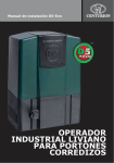
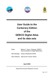
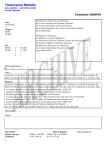
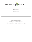
MANUEL D’UTILISATION / USER MANUAL VANNE Y ATEQ Versions "Standard" et "Détection de position" ATEQ Y VALVE "Standard" and "Position detection" versions (Photo non contractuelle / Non contractual picture) Référence / Reference : UM-92000C-F REVISIONS DU MANUEL VANNE Y ATEQ Edition/Révision Référence Date sem/an Mises à jour Première édition 9244 44/1992 ----- Deuxième édition UM-92010B-F 08/2005 Mise à jour complète 29/2005 Modification nomenclature dans paragraphe "caractéristiques mécaniques" dans chapitre "Option de détection de position". Troisième édition UM-92010C-F REVISION OF THE Y VALVE USER MANUAL Edition/ Revision Reference Date (week/year) Updates ----- First edition 9244 44/1992 Second edition UM-92010B-F 08/2005 General updating of the manual. Third edition UM-92010C-F 29/2005 Parts list modification in the "Mechanicals features" in the "position detection option" chapter. Recommandations pour appareils de tests d’étanchéité Considérations sur l’environnement de test • Laisser l’aire de test la plus propre possible. Considérations sur les opérateurs • ATEQ recommande que les opérateurs amenés à utiliser les appareils aient une formation et un niveau de qualification en adéquation avec le poste de travail. Considérations générales • Lire le manuel d’utilisation avant toute utilisation de l’appareil, • toutes les connexions électriques arrivant sur l’appareil doivent être équipées de systèmes de sécurité (fusibles, disjoncteurs …) adaptés aux besoins et conformes aux normes en vigueur, • pour éviter des perturbations électromagnétiques, les connexions électriques effectuées sur l’appareil doivent être inférieures à 2 mètres, • la prise électrique d’alimentation doit obligatoirement comporter une connexion à la terre, • débrancher électriquement l’appareil pour toute intervention de maintenance, • couper l’alimentation en air comprimé lors de toute intervention sur le montage pneumatique, • ne pas ouvrir l’appareil sous tension, • éviter les projections d’eau en direction de l’appareil, • ATEQ se tient à votre disposition pour tout renseignement concernant l’utilisation de l’appareil dans les conditions maximales de sécurité. Nous attirons votre attention sur le fait que la société ATEQ ne saurait être tenue pour responsable de tout accident lié à la mauvaise utilisation de l’instrument de mesure, du poste de contrôle ou à la non-conformité de l’installation aux règles de sécurité. De plus, la Société ATEQ se dégage de toute responsabilité sur l'étalonnage ou l'ajustage de ses instruments qui ne serait pas effectué par ses soins. La Société ATEQ se dégage aussi de toute responsabilité en cas de modification (programme, mécanique ou électrique) de l'appareil sans son accord écrit. 0039/Ret-F Recommendations for leak testing instruments Precautions for the test environment • Keep the test area as clean as possible. Precautions for the operators • ATEQ recommends that the operators using the instruments should have a suitable qualification and training with respect to the work bench requirements. General precautions • Read the user manual before using the instrument, • all electrical connections to the instrument must be equipped with a safety system (fuse, circuit breaker…) appropriate to its needs and complying with the standards, • to avoid electromagnetic interference, the cable connections to the instrument should be less than two meters in length, • it is essential that the electrical main is earthed, • disconnect the electrical connections to the equipment before maintenance, • cut the air supply for any kinds of operation on the pneumatic assembly, • do not open the instrument when it is powered up, • avoid water spillage near of the instrument, • ATEQ is at your disposal for any further information concerning the use of the instrument under maximum safety conditions. We would like to bring to your attention that ATEQ will not be held responsible for any accident connected to the improper use of the instrument, to the work bench or to the lack of compliance with safety rules. ATEQ Company is free from any responsibility for any adjustment of its instrument which would not have been done by its own technicians. The ATEQ cannot be held responsible if the instrument (program, mechanics or electronics) has been modified without prior written consent. 0039/Ret-U ATEQ, L’ASSURANCE D’UN SERVICE APRES VENTE COMPETENT LE S.A.V. D’ATEQ C’EST : • une équipe de techniciens qualifiés, • une assistance téléphonique permanente, • des agences proches de chez vous pour une meilleure réactivité, • un stock de pièces détachées disponibles immédiatement, • un parc automobile pour intervenir rapidement, • un engagement qualité ... LES REVISIONS ATEQ effectue la révision de vos appareils à un prix intéressant. Cette révision correspond à l’entretien des instruments (vérification, nettoyage, changement des pièces d’usure) dans le cadre d’une maintenance préventive. L'entretien préventif est le meilleur remède pour garantir un matériel efficace. Il permet de maintenir un parc d’appareils en état de fonctionnement en prévenant les pannes éventuelles. LES KITS D'ENTRETIEN Le S.A.V. d'ATEQ propose, pour une meilleure prévention, deux kits d'entretien pour la pneumatique de ces appareils. L'ETALONNAGE Celui-ci peut être réalisé en nos locaux ou sur site. ATEQ est raccordé au COFRAC et délivre un certificat après étalonnage. LES FORMATIONS Dans le cadre du partenariat avec nos clients, ATEQ propose deux types de formations afin d’optimiser l’utilisation et la connaissance de nos appareils. Elles s’adressent à différents degrés de techniciens : • Formation méthode / contrôle, • Formation maintenance / entretien. UNE DOCUMENTATION TECHNIQUE CIBLEE Une documentation technique est mise à votre disposition pour vous permettre d’intervenir rapidement sur des pannes de petite importance : • des fiches problèmes décrivant et solutionnant les principaux problèmes pneumatiques et électroniques, • des manuels de maintenance. UNE GARANTIE DE LA QUALITE Les appareils sont garantis pièces et main d’œuvre en nos locaux : • 2 ans pour les appareils de contrôle d’étanchéité, • 1 an pour les appareils de contrôle de conformité aux normes électriques, • 1 an pour les accessoires. Notre Service après vente est capable de répondre rapidement à tous les besoins que vous pouvez rencontrer. ATEQ préconise de faire réaliser par ses services une révision et un étalonnage annuel des appareils 0241/SAVb-F ATEQ, THE ASSURANCE OF A COMPETENT AFTER SALES SERVICE THE ATEQ AFTER SALES SERVICE IS : • a team of qualified technicians, • a permanent telephone assistance, • agencies close to you for faster reaction, • a stock of spare parts available immediately, • a car fleet for rapid intervention, • a commitment to quality ... THE OVERHAUL ATEQ carries out the overhaul of your instruments at interesting prices. The overhaul corresponds to the maintenance of the instrument (checking, cleaning, replacing of used parts) as part of preventive maintenance. Preventive maintenance is the best way to guarantee reliability and efficiency. It allows the maintenance of a group of instruments in good operational order and prevent eventual break-downs. MAINTENANCE KITS The ATEQ After Sales Service proposes, two kits destined for the preventive maintenance of the pneumatic circuits of instruments. CALIBRATION This may be carried out on site or in our offices. ATEQ is attached to the COFRAC and delivers a certificate following a calibration. TRAINING COURSES In the framework of partnership with our customers, ATEQ offers two types of training in order to optimise the usage and knowledge of our instruments. They are aimed at different levels of technician: • method / control training, • maintenance / upkeep training. A TARGETED TECHNICAL DOCUMENTATION A number of technical documents are at your disposal to allow you to intervene rapidly in the event minor breakdowns: • problem sheets describing and offering solutions to the main pneumatic and electronic problems, • several maintenance manuals. A QUALITY GUARANTEE The instruments are guaranteed for parts and labour in our offices: • 2 years for leak detection equipment, • 1 year for electrical tests to norms instruments, • 1 year for the accessories. Our After Sales Service is capable of rapidly answering all your needs and queries. ATEQ recommends to made realise by its departments a revision and a calibration of the instruments every year SAV-Ub/0243 PREFACE Cher client, Vous venez d’acquérir un appareil ATEQ et nous vous remercions de la confiance que vous témoignez à notre marque. Cet instrument a été conçu pour vous assurer une longévité hors pair et nous sommes convaincus qu’il vous donnera une entière satisfaction pendant de longues années de fonctionnement. Afin d’obtenir la meilleure durée de vie possible et une fiabilité maximale de votre ATEQ, nous vous recommandons vivement de mettre cet appareil sur un plan de travail sécurisé. Notre centre SAV ATEQ peut vous donner des conseils adaptés à vos conditions d’utilisation spécifiques. ATEQ 0508/PREc-F PREFACE Dear Customer, You have just purchased an ATEQ instrument, we thank you for the trust you have placed on our brand. This instrument has been designed to ensure a long and unparalleled life expectancy, and we are convinced that it will give you complete satisfaction during many long years of operation. In order to maximise the life expectancy and reliability of your ATEQ instrument, we recommend that you install this instrument on a secured workbench and advise you to consult this manual in order to familiarise yourself with the functions and capabilities of the instrument. Our ATEQ After Sales Service centre can give you recommendations based on your specific operation requirements. ATEQ 0508/PREFc-U TABLE DES MATIERES / TABLE OF CONTENTS Chapitre 1 / Chapter 1 PRESENTATION / PRESENTATION 1. PRESENTATION / PRESENTATION 2. SCHEMA PNEUMATIQUE EQUIVALENT / EQUAL PNEUMATIC DIAGRAM 3. CARACTERISTIQUES PNEUMATIQUES / PNEUMATICS FEATURES 4. PASSAGE EN POSITION REPOS / REST POSITION PASSING Chapitre 2 / Chapter 2 3 3 3 4 INSTALLATION / INSTALLATION 1. TEST / SUCCESSIVE TESTING 5 2. RÉFÉRENCE / SWITCHING REFERENCES 7 3. VIDAGE DÉPORTÉ / EXTERNAL DUMP 8 4. VIDAGE DÉPORTÉ (VARIANTE) / EXTERNAL DUMP (ALTERNATIVE) 9 5. REMPLISSAGE / FILLING BEFORE START OF CYCLE 10 6. VANNE Y EN SÉRIE / SERIAL Y VALVE 11 7. REMPLISSAGE AVEC PLUSIEURS VANNES Y EN SERIE / FILLING WITH SEVERAL SERIAL Y VALVES 12 8. TEST SUR UNE PIECE A DEUX CHAMBRES / TEST ON A COMPONENT WITH TWO CHAMBERS13 9. VANNE Y POUR ETALONNAGE / Y VALVE FOR CALIBRATION CHECK 14 Chapitre 3 / Chapter 3 CARACTERISTIQUES / FEATURES 1. PLANS MECANIQUES SERIE 3 / MECHANICAL DRAWINGS 3RD SERIE Chapitre 4 / Chapter 4 ENTRETIEN / MAINTENANCE 1. ENTRETIEN VANNE Y SERIE 3 / 3RD SERIES Y VALVE MAINTENANCE 1.1. Démontage vanne Y série 3 / Disasembling Y valve 3rd series 1.2. Nettoyage vanne Y série 3 / Cleaning Y valve 3rd series 1.3. Remontage vanne Y série 3 / Reassembly Y valve 3rd series 1.4. Nomenclature vanne Y série 3 / Parts list Y valve 3rd series 1.5. Kits vanne Y série 3 / Y valve 3rd series kits Chapitre 5 / Chapter 5 23 23 24 25 26 DETECTION POSITION / POSITION DETECTION 1. CARACTERISTIQUES ELECTRIQUES / ELECTRICALS FEATURES 2. CARACTERISTIQUES MECANIQUES / MECHANICALS FEATURES 3. CARTE DE DETECTION DE POSITION / POSITION DETECTION BOARD 3.1. Configuration / Configuration 3.2. Câblage mode PNP ou NPN / PNP or NPN wiring mode 3.3. Câblage mode série 5 / ATEQ 5th serie wiring mode UM-92010C-F 17 17 18 19 20 21 PARTICULARITE SERIE 4 / 4TH PARTICULARITY 1. VANNE Y SERIE 4 / Y VALVE 4TH SERIE 1.1. Encombrements / Dimensions 1.2. Vue d'ensemble / General view 1.3. Nomenclature / Part list 2. KITS VANNE Y SÉRIE 4 / Y VALVE 4TH SERIES KITS Chapitre 6 / Chapter 6 15 Manuel d'utilisation Vanne Y / User manual Y Valve 1 / 30 27 28 29 29 29 30 UM-92010C-F Manuel d'utilisation Vanne Y / User manual Y Valve 2 / 30 Chapitre 1 / Chapter 1 PRESENTATION / PRESENTATION 1. PRESENTATION / PRESENTATION Vanne Y Y Valve La vanne Y est une vanne étanche 3/2 à The Y valve is 2/3 pressurized leak-tight rappel par ressort avec pilotage valve, pneumatically piloted. pneumatique. It can be used either ways for different Cette vanne peut être montée purposes: indifféremment dans un sens ou dans It is used for any other tight application l'autre. having to be leak-tight guaranteed with a Elle est utilisée pour toute autre Y. application devant être garantie étanche The principal uses of the valve Y are as avec un Y. follows: Les utilisations principales de la vanne Y sont les suivantes : 2. SCHEMA PNEUMATIQUE EQUIVALENT / EQUAL PNEUMATIC DIAGRAM PRESSURISATION / PRESSURIZATION 3. CARACTERISTIQUES PNEUMATIQUES / PNEUMATICS FEATURES PRESSION D'ALIMENTATION / SUPPLY PRESSURE PRESSION DE TEST / TEST PRESSURE 4 (quatre) bars minimum / 4 (four) bars Vide et pression / Vacuum and pressure. minimum. 10 (dix) bars maximum / 10 (ten) bars 10 (dix) bars maximum / 10 (ten) bars maximum. maximum. UM-92010C-F Manuel d'utilisation Vanne Y / User manual Y Valve 3 / 30 4. PASSAGE EN POSITION REPOS / REST POSITION PASSING UM-92010C-F Manuel d'utilisation Vanne Y / User manual Y Valve 4 / 30 Chapitre 2 / Chapter 2 INSTALLATION / INSTALLATION 1. TEST / SUCCESSIVE TESTING L'utilisation la plus courante de la vanne Y The most common utilization of the Y est représentée sur le schéma suivant valve is shown on diagram 1. (schéma n°1). The Y valve is used for 2 chained cycles La vanne Y est utilisée pour effectuer on two different components. deux tests successifs. A 24V solenoid mounted on the valve and Une électrovanne, montée sur la vanne Y, is controlled either from the valve code of alimentée en 24 V continu est the instrument, either from a PLC. commandée soit par le code vanne, soit par l'automate du client. TEST / TEST PRESSURISATION / PRESSURIZATION TEST 1 / TEST 1 REFERENCE / REFERENCE TEST 2 / TEST 2 ECHAP. / EXHAUST. 6 BAR FILTRE / FILTERED LINE PRESSURE INPUT Schéma n°1 : Test Diagram n°1: Test UM-92010C-F Manuel d'utilisation Vanne Y / User manual Y Valve 5 / 30 L'électrovanne peut aussi être The solenoid can also be independent and indépendante et doit alimenter en air feed the valve with the line pressure for comprimé (6 bars permanents) la vanne Y shifting the valve correctly (diagram n°2). pour le déplacement du tiroir (schéma n° 2). TEST / TEST PRESSURISATION / PRESSURIZATION TEST 1 / TEST 1 REFERENCE / REFERENCE ECHAP. / EXHAUST. ELECTROVANNE / SOLENOID TEST 2 / TEST 2 CAPOT / CAP 6 BAR FILTRE / FILTERED LINE PRESSURE INPUT Schéma n°2 : pilotage externe Diagram n°2: independant solenoid UM-92010C-F Manuel d'utilisation Vanne Y / User manual Y Valve 6 / 30 2. REFERENCE / SWITCHING REFERENCES Un montage moins fréquent est d'utiliser la vanne Y pour basculer d'une référence sur une autre, dans le cas où sur la chaîne de production deux pièces différentes seraient à tester (schéma n° 3). Also the Y valve can be used for having 2 different reference volumes whenever to different components have to be tested on the line (diagram n°3). As on diagram 2, the solenoid can be Comme ci dessus, l'électrovanne de mounted on the valve or in the instrument commande peut être montée sur la vanne case. elle même ou être indépendante. TEST / TEST PRESSURISATION / PRESSURIZATION REF 1 / REF 1 REFERENCE / REFERENCE REF 2 / REF 2 ECHAP. / EXHAUST. 6 BAR FILTRE / FILTERED LINE PRESSURE INPUT Schéma n°3 : référence Diagram n°3: switching references UM-92010C-F Manuel d'utilisation Vanne Y / User manual Y Valve 7 / 30 3. VIDAGE DEPORTE / EXTERNAL DUMP Le vidage déporté est utilisé pour éviter External dump is used to avoid water, oil, toute remontée de poussières ou de dust, particles to reach the ATEQ unit saletés dans l'ATEQ (schéma n°4). when dumping through the main valve La deuxième sortie de la vanne est en block (diagram n°4). échappement au repos. The second exit of the valve is in exhaust Ce montage est utilisé en contrôle at rest. d'étanchéité et nécessite soit un code External dump is controlled via the valve vanne de l'ATEQ F pour commander la code, so the Y valve is activated during all vanne (le programme utilise deux codes cycle and deactivated when dumping (the vannes), soit une commande externe. program is using two valves codes). TEST / TEST 6 BAR FILTRE / FILTERED PIECE / COMPONENT LINE PRESSURE INPUT PRESSURISATION / PRESSURIZATION REFERENCE / REFERENCE ECHAP. / EXHAUST. ECHAPPEMENT AU REPOS / DUMPING OUTPUT Schéma n°4 : vidage déporté Diagram n°4: external dump UM-92010C-F Manuel d'utilisation Vanne Y / User manual Y Valve 8 / 30 4. VIDAGE DEPORTE (VARIANTE) / EXTERNAL DUMP (ALTERNATIVE) Pour éviter des problèmes de débit, la vanne Y ne se monte pas en série avec l'appareil (schéma n°5). Une des sorties est en échappement au repos, l'autre est connectée sur un bouchon. The Y valve is sometimes a restrictive flow compared to the application (big volume components). On diagram 5, the Y valve will only be used to dump and not be restrictive as on external dump. TEST / TEST PRESSURISATION / PRESSURIZATION REFERENCE / REFERENCE 6 BAR FILTRE / FILTERED LINE PRESSURE INPUT PIECE / COMPONENT BOUCHON / CAP ECHAP. / EXHAUST. ECHAPPEMENT AU REPOS / DUMPING OUTPUT schéma n°5 : vidage diagram n°5: dumping UM-92010C-F Manuel d'utilisation Vanne Y / User manual Y Valve 9 / 30 5. REMPLISSAGE / FILLING BEFORE START OF CYCLE Il est possible d'insuffler de l'air (ex 150 It is possible to start filling component mbar) pour permettre un remplissage de while test has not started yet (diagram la pièce en temps masqué (schéma n°6). n°6). TEST / TEST 6 BAR FILTRE / FILTERED LINE PRESSURE INPUT PIECE / COMPONENT PRESSURISATION / PRESSURIZATION REFERENCE / REFERENCE ECHAP. / EXHAUST. REMPLISSAGE 150 mBAR / 150 mBAR FILLING schéma n°6 : remplissage diagram n°6: filling UM-92010C-F Manuel d'utilisation Vanne Y / User manual Y Valve 10 / 30 6. VANNE Y EN SÉRIE / SERIAL Y VALVE Il est possible d'utiliser plusieurs vannes Y It's possible to use several Y valves of en série pour tester plusieurs pièces par series to test several parts by only one un seul appareil (schéma n°7). instrument. TEST 1 / TEST 1 TEST 2 / TEST 2 TEST / TEST PRESSURISATION / PRESSURIZATION TEST 3 / TEST 3 REFERENCE / REFERENCE TEST 4 / TEST 4 ECHAP. / EXHAUST 6 BAR FILTRE / FILTERED LINE PRESSURE INPUT Schéma n°7 : vanneY en cascade Diagram n°7: serial Y valve Test de plusieurs composants en même temps / One instrument to make several tests UM-92010C-F Manuel d'utilisation Vanne Y / User manual Y Valve 11 / 30 7. REMPLISSAGE AVEC PLUSIEURS VANNES Y EN SERIE / FILLING WITH SEVERAL SERIAL Y VALVES Le schéma de montage est le même que pour un remplissage simple (schéma n°6), mais les vannes sont montées en série. Le cycle se déroule comme suit : le bouchonnage se ferme permettant aux pièces de se remplir puis le F3 vient explorer chaque pièce l'une après l'autre en basculant successivement les vannes Y. L'automate peut piloter les vannes Y les unes après les autres, permettant des temps de contrôle par pièce très court. Cela s'utilise surtout pour des pièces de faibles volumes. Voir sur le schéma ci dessous. Several valves can be used to fill at the same pressure several components that will be tested in an automatic chained sequence controlled from the instrument. All components are pressurized at the same time, then the ATEQ F successively switches the Y valves to leak test the components. This method allows shorter cycle time especially for small volume components. TEST / TEST REFERENCE / REFERENCE ECHAP. / EXHAUST. SORTIE REGULATEUR / REGULATOR OUTPUT 6 BAR FILTRE / FILTERED PIECE 2 / COMPONENT 2 LINE PRESSURE INPUT 6 BAR FILTRE / FILTERED PIECE 1 / COMPONENT 1 LINE PRESSURE INPUT PRESSURISATION / PRESSURIZATION Nota : le nombre de vannes doit rester limité. / Note: the number of valve must be limited. UM-92010C-F Manuel d'utilisation Vanne Y / User manual Y Valve 12 / 30 8. TEST SUR UNE PIÈCE À DEUX CHAMBRES / TEST ON A COMPONENT WITH TWO CHAMBERS TEST / TEST PRESSURISATION / PRESSURIZATION ECHAP. / EXHAUST. REFERENCE / REFERENCE ECHAP. / EXHAUST. 6 BAR FILTRE / FILTERED LINE PRESSURE INPUT Dans le s'effectue deuxième ceci pour interne. cas présent, le premier test sur la totalité de la pièce, le test s'effectue sur une chambre déceler une fuite sur la paroi UM-92010C-F In the present case, the first test is done on the whole component, the second test is done on one side of the component to detect an internal leak, after the other side has been dumped. Manuel d'utilisation Vanne Y / User manual Y Valve 13 / 30 9. VANNE Y POUR ETALONNAGE / Y VALVE FOR CALIBRATION CHECK Il est possible d'utiliser la vanne Y pour The Y valve can be used for checking vérifier l'étalonnage en poste manuel. calibration of the instrument. In this case, Une des sorties est branchée sur une fuite a master calibrated leak will be installed on one of the Y valve output. (diagram 8). étalon (schéma n°8). TEST / TEST PRESSURISATION / PRESSURIZATION REFERENCE / REFERENCE 6 BAR FILTRE / FILTERED LINE PRESSURE INPUT PIECE / COMPONENT BOUCHON / CAP ECHAP. / EXHAUST. FUITE ETALON / CALIBRATED LEAK schéma n°8_étalonnage diagram n°8_ calibration UM-92010C-F Manuel d'utilisation Vanne Y / User manual Y Valve 14 / 30 Chapitre 3 / Chapter 3 CARACTERISTIQUES / FEATURES 1. PLANS MECANIQUES SERIE 3 / MECHANICAL DRAWINGS 3RD SERIE UM-92010C-F Manuel d'utilisation Vanne Y / User manual Y Valve 15 / 30 UM-92010C-F Manuel d'utilisation Vanne Y / User manual Y Valve 16 / 30 Chapitre 4 / Chapter 4 ENTRETIEN / MAINTENANCE 1. ENTRETIEN VANNE Y SERIE 3 / 3RD SERIES Y VALVE MAINTENANCE 1.1. DEMONTAGE VANNE Y SERIE 3 / DISASEMBLING Y VALVE 3RD SERIES 1. Démonter le corps de la butée guide 1. Unscrew the spring guide body 88-10688-106-02-E0 côté ressort 6130003, en 02-E0 on spring side 6130003 enlevant les 2 vis 6100282. removing the 2 screws 6100282. Une fois dévissé, le corps est When unscrewed, the body is «poussé» par le ressort. «pushed» by the spring. 2. De l’autre côté de la vanne, enlever les 2. On the other side of the valve, remove 2 vis 6100121. Puis retirer le corps du the 2 screws 6100121. Then remove poussoir 88-106-04-UT. Si la clé ne the pusher body 88-106-04-UT. If permet pas de dévisser, utiliser une impossible to unscrew with hexagonal pince multiprise ou équivalent. wrench use water pump pliers or equivalent. 3. Pousser délicatement le tiroir 88-10606-E0 à l’aide d’un outil non 3. Push gently the spool 88-106-06-E0 métallique (tuyau RILSAN, crayon à using a non metallic tool (nylon or papier...). polyamide tubing, wooden pencil). 4. Retirer les guides vanne 88-106-16-U0. 4. Remove the valve guides 88-106-16U0. 5. Pousser l’ensemble entretoises 88-09502-UT + joint toriques 6310035 toujours 5. Push the assemblies' spacers 88-095avec un outil non métallique pour 02-UT + O-ring 6310035 still with a non éviter de rayer le corps de vanne. metallic tool to prevent scratching on the cylinder bore of the valve. Corps de vanne rayé = Vanne inutilisable Scratching on cylinder bore = Valve out of order UM-92010C-F Manuel d'utilisation Vanne Y / User manual Y Valve 17 / 30 1.2. NETTOYAGE VANNE Y SÉRIE 3 / CLEANING Y VALVE 3RD SERIES KIT 1 (joints + ressort + vis + graisse) KIT 1 (O-ring + spring + screws + grease) • Prendre les guides vanne 88-106-16U0, les entretoises 88-095-02-UT, le • Take the valve guides 88-106-06-U0, tiroir 88-106-06-E0 et les placer dans the spacer's 88-095-02-UT the spool un liquide dégraissant (trichloréthylène 88-106-06-E0, and put everything in a ou équivalent). bath of degreasing liquid (trichloroethylene or equivalent). • Sortir les pièces et les souffler (air sec et propre). • Then remove this part from the bath and blow them with clean and dry air. • Si besoin est, nettoyer l’intérieur du corps de vanne 88-106-14-UT avec le • If necessary, clean the cylinder bore of même produit et un chiffon ou un papier valve 88-106-14-UT with the same non pelucheux. Si des marques sont liquid and a non fluffy cloth or paper. In présentes sur le tiroir 88-106-06-E0, case of marks on the spools it is effectuer un polissage avec une pâte à possible to polish them using a polir ou un produit équivalent. polishing pasty or equivalent. KIT 2 (KIT 1 + piston poussoir + joint + KIT 2 (KIT 1 + spool + piston pusher + tiroir) O-ring) • Il n’est pas nécessaire de nettoyer le • It is not necessary to clean the spool tiroir 88-106-06-E0. 88-106-066-E0. • Pour placer le piston poussoir 88-106- • Install the pusher's cylinder 88-106-0505-U0 avec son joint à lèvres 6310003, U0 and their lip rings 6310003, using a utiliser un petit tournevis pour guider le small screwdriver to guide the seal in joint dans l’alésage du corps du the body boring 88-106-04-UT. poussoir 88-106-04-UT. UM-92010C-F Manuel d'utilisation Vanne Y / User manual Y Valve 18 / 30 1.3. REMONTAGE VANNE Y SERIE 3 / REASSEMBLY Y VALVE 3RD SERIES Tous les pistons, guides, entretoises, tiroirs, ressorts et joints doivent être légèrement graissés avec la graisse type B431 fournit avec le kit d’entretien. All the pistons, guides, spacers, spools, springs and O-ring must be slightly greased with B 431 type grease supplied with the service kit. 1. Put successively in the body 88-1061. Mettre en place successivement dans 14-UT, the 8 O-ring 6310035 and the le corps 88-106-14-UT, les 8 joints 7 spacers 88-095-02-UT (fig.2). 6310035 ainsi que les 7 entretoises 882. Place the spool 88-106-06-E0 in the 095-02-UT (fig.2). cylinder bore respecting the mounting 2. Mettre en place le tiroir 88-106-06-E0 direction (tight tap 6360005 on spring dans l'alésage en respectant le sens de side) (fig.2). montage (bouchon étanche 6360005 3. Place the valve guides 88-106-16-U0 du côté ressort) (fig.2). on each side of the cylinder bore. 3. Mettre en place les guides vanne 884. Place the pushing piston 88-106-05106-16-U0 à chaque extrémité de U0 and the O-ring 6310003 in the l'alésage. pusher body 88-106-04-UT. Place the 4. Mettre le piston poussoir 88-106-05O-ring 6310130 (fig.1). U0 et le joint 6310003 dans le corps de 5. Place the pusher body 88-106-04-UT poussoir 88-106-04-UT. Placer le joint mounted, with the 2 screws 6100121. 6310130 (fig.1). Place the spring guide 88-106-03-U0 5. Placer le corps de poussoir 88-106and the spring 6130003 in the body 04-UT équipé, à l'aide des 2 vis 88-106-02-E0. 6210121. 6. Then place the body 88-106-02-E0 6. Mettre le guide ressort 88-106-03-U0 with the 2 screws 6100282. et le ressort 6130003 dans le corps 887. Run the valve for a minimum of 12 106-02-E0. hours. Puis placer le corps 88-106-02-E0 avec les 2 vis 6100282. 7. Faire cycler la vanne pendant 12 heures. UM-92010C-F Manuel d'utilisation Vanne Y / User manual Y Valve 19 / 30 1.4. NOMENCLATURE VANNE Y SERIE 3 / PARTS LIST Y VALVE 3RD SERIES DESIGNATION / DESIGNATION Corps de vanne / Valve body. Corps de la butée guide / Spring guide body. Corps du poussoir / Pusher body. Guide vanne / Valve guide. Guide du ressort / Spring guide. Piston poussoir / Cylinder pusher. Tiroir / Spool. Entretoise / Spacer. Ressort / Spring. Vis M4 x 40 / M4 x 40 Screw. Vis M4 x 50 / M4 x 50 Screw. Joint torique / O’ring. CODE ATEQ / ATEQ CODE 88-106-14-UT 88-106-02-E0 88-106-04-UT 88-106-16-U0 88-106-03-U0 88-106-05-U0 88-106-06-E0 88-095-02-UT 6130003 6100121 6310282 6310125 6310035 6310003 QUANTITE / QUANTITY 1 1 1 2 1 1 1 7 1 2 2 1 8 1 6360005 2 Bouchon étanche (non démontable, livré dans le corps) / Tight tap (nondismountable, deliver in the body). 6300118 6360005 6300256 88-106-02-E0 6340018 6310125 6360005 88-106-04-UT 6100282 6100121 6130003 88-106-03-U0 88-106-05-U0 88-106-14-UT 88-106-06-E0 6310003 6300116/6300121/6300114/6300159 Fig.1 88-095-02-UT 88-106-06-E0 6310035 6360005 Bouchon étanche / Tight tap 88-106-16-U0 UM-92010C-F Fig.2 Manuel d'utilisation Vanne Y / User manual Y Valve 20 / 30 1.5. KITS VANNE Y SÉRIE 3 / Y VALVE 3RD SERIES KITS KIT 1 KIT 2 Joint / O-ring 9.19 x 2.62 8 x 6310035 Kit 1 + Joint / O-ring 3.4 x 1.9 1 x 6310125 Tiroir / Spool 1 x 88-106-06-E0 Ressort / Spring 1 x 6130003 Piston poussoir / Cylinder pusher 1 x 88-106-05-U0 Vis / Screw CHc M4 x 40 2 x 6100121 Joint à lèvre / Lip seal 20 x 13 x 2.3 1 x 6310003 Vis / Screw CHc M4 x 50 2 x 6100282 Graisse / Grease type B431 6 bars test Pressurisation / Pressurization Test UM-92010C-F Manuel d'utilisation Vanne Y / User manual Y Valve 21 / 30 UM-92010C-F Manuel d'utilisation Vanne Y / User manual Y Valve 22 / 30 Chapitre 5 / Chapter 5 PARTICULARITE SERIE 4 / 4TH PARTICULARITY 1. VANNE Y SERIE 4 / Y VALVE 4TH SERIE 1.1. ENCOMBREMENTS / DIMENSIONS UM-92010C-F Manuel d'utilisation Vanne Y / User manual Y Valve 23 / 30 1.2. VUE D'ENSEMBLE / GENERAL VIEW UM-92010C-F Manuel d'utilisation Vanne Y / User manual Y Valve 24 / 30 1.3. NOMENCLATURE / PART LIST REP. QUANT. 1 1 Guide butée ressort / Spring stop guide. 8810621 2 1 Guide ressort / Spring guide. 8810622 3 1 Tiroir / Drawer. 4 1 Ensemble corps équipé / Body equipped set. 9200018 5 2 Guide vanne (laiton) / Valve guide (brass). 8809506 Guide vanne (delrin) / Valve guide (delrin). 9200112 6 7 Entretoise / Spacer. 8809502UT 7 2 Rondelle de compression / Compression disc. 88095XXU0 8 1 Vis HC à bout plat M6 x 6 / Flat end HC M6 x 6 screw. 6100250 9 8 Joint torique / O-ring. 6100035 10 1 Ressort de compression / Compression spring. 6130003 11 2 Vis CHc M4 x 16 / CHc M4 x 16 screw. 6100258 12 1 Piston poussoir / Pusher piston. 9200139 13 1 Joint à lèvre / Lip seal. 6310003 14 1 Raccord droit instantané 4-6 / Intantaneous straight plug 4-6. 6300145 Union male cylindrique 3-5 / Cylindric male union plug 35. 6300256 Union male cylindrique 2.5-4 / Cylindric male union plug 2.5-4. 6300111 15 1 DESIGNATION CODE 9200228E0 16* 1 Bouchon de corps pilote / Driver body cap. 17* 1 Joint torique / O-ring. 6310134 18* 2 Vis autotaraudeuse Ø 3 x 10 / Autotapping screw Ø 3 x 10. 6100327 19 1 Electrovanne connector. 6340075 20 1 Corps de poussoir / Pusher body. et connecteur / Electrovalve 8810609E0 and 21 2 Vis CHc M4 x 45 / CHc M4 x 45 screw. * : Nota : les repères 16, 17 et 18 concernent l'option pilotage pneumatique. 9200368 6100251 *: Note: the 16, 17 and 18 marks are concerning the pneumatic driving option. UM-92010C-F Manuel d'utilisation Vanne Y / User manual Y Valve 25 / 30 2. KITS VANNE Y SERIE 4 / Y VALVE 4TH SERIES KITS KIT 1 KIT 2 Joint / O-ring 9.19 x 2.62 8 x 6310035 Kit 1 + Joint / O-ring 3.4 x 1.9 1 x 6310125 Tiroir / Spool 1 x 9200228 Ressort / Spring 1 x 6130003 Piston poussoir / Cylinder pusher 1 x 9200139 Vis / Screw CHc M4 x 45 2 x 6100251 Joint à lèvre / Lip seal 20 x 13 x 2.3 1 x 6310003 Vis / Screw CHc M4 x 16 2 x 6100258 Graisse / Grease type B431 UM-92010C-F Manuel d'utilisation Vanne Y / User manual Y Valve 26 / 30 Chapitre 6 / Chapter 6 OPTION DETECTION POSITION / POSITION DETECTION OPTION 1. CARACTERISTIQUES ELECTRIQUES / ELECTRICALS FEATURES La vanne série 5 peut avoir en option une détection de position du tiroir, afin d'avoir la certitude du mouvement du tiroir dans la vanne. The valve series 5 can have in option a detection of position of the drawer, in order to have the certainty of the movement of the drawer in the valve. Connecteur type Lumberg M8. M8 Lumberg type connector. Consommations : 28 V maximum, 40 mA Consumption: 28 V maximum, 40 mA maximum, Sortie signal 20 mA maximum. maximum, output signal 20 mA maximum. Un voyant s'allume pour indiquer la position travail du tiroir, ce voyant est visible par transparence derrière le capot plastique du côté du ressort. An indicator lights to indicate the position work of the drawer, this indicator is visible by transparency behind the plastic cap on the spring side. 24 V DC 1 : 24 V DC VANNE Y / Y V ALVE 4 : Signal 20 mA Charge NPN Load 0 V DC 3 : 0 V DC OU / OR (CHOIX A LA COMMANDE) (CHOICE AT THE ORDER) 1 : 24 V DC VANNE Y / Y V ALVE 24 V DC 4 : Signal 20 mA 3 : 0 V DC Charge PNP Load 0 V DC UM-92010C-F Manuel d'utilisation Vanne Y / User manual Y Valve 27 / 30 2. CARACTERISTIQUES MECANIQUES / MECHANICALS FEATURES REP. QUANT. DESIGNATION CODE 1 1 Ensemble corps équipé / Equiped body set. 9200018 2 1 Ensemble corps de poussoir / Pusher body set. 9200368 3 1 Entretoise embout / Spacer. 9200013 4 1 Pointe de détection / detection point. 9200030 5 1 Embout ressort / Spring end. 9200469 6 2 Vis CHc M4 x 60 / CHc M4 x 60 screws 6100124 7 1 Capot de protection / Protection cap. 9200039 9 2 Vis CHc M3 x 16 / CHc M3 x 16 screws 6100100 1 Ensemble câble comprenant / Cable set containing: 5050311 1 ¾ Câble M8 mâle / Male M8 cable. 1 ¾ Collier en P / P body plastic to pass the cable. 6210008 1 ¾ Porte repère transparent / Transparent carry label. 6210303 1 ¾ Carte de détection position / Position detection board. 8 ¾ Fiche M8 femelle / Female connector M8. UM-92010C-F 520.34 6200688 Manuel d'utilisation Vanne Y / User manual Y Valve 28 / 30 3. CARTE DE DETECTION DE POSITION / POSITION DETECTION BOARD 3.1. CONFIGURATION / CONFIGURATION Il est possible de configurer un mode de It's possible to configure one functioning fonctionnement parmi les trois disponibles : mode among three available: ¾ Mode automate PNP, ¾ PNP PLC mode, ¾ Mode automate NPN, ¾ NPNPLC mode, ¾ Mode série 5 ATEQ (utilisation sur carte microprocesseur 550.11). ¾ 5th serie ATEQ (use microprocessor board 550.11). with Pour cela, il faut réaliser un pont de For that, it is necessary to carry out a soudure entre les deux pastilles bridge of welding between the two correspondantes. corresponding pastilles. Matériel à utiliser : un fer à soudure à l'étain. souder, Material to be used: a soldering iron, welding with tin. 3.2. CABLAGE MODE PNP OU NPN / PNP OR NPN WIRING MODE Fil / Wire Broches / Pins 1 – Marron / Brown = +24V (+). 6210303 Câble M8 (5050311) UM-92010C-F 250 20 3 – Bleu / Blue = 0V (-). 4 – Noir / Black = Signal (S). Manuel d'utilisation Vanne Y / User manual Y Valve 29 / 30 3.3. CABLAGE MODE SERIE 5 / ATEQ 5TH SERIE WIRING MODE + 1 S - Connecteur carte microprocesseur 550.11 / 550.11 Microprocessor board connector. UM-92010C-F Manuel d'utilisation Vanne Y / User manual Y Valve 30 / 30 Ce document est la propriété exclusive d’ATEQ. Il ne peut être communiqué, reproduit ou utilisé sans accord préalable. This document is the exclusive property of ATEQ. It may not be communicated, reproduced or used without prior consent.