1
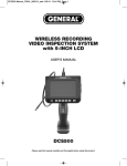
Strobe controller FL-01CX
Compact reliable strobe controller can remotely
control the flash rate of 1 to 4 strobes.
Flash rate can be set from 1 to 10 flashes per second.
CAUTION!
2002
Risk of electric shock
Read instructions before installing
or connecting to power
Operating instructions
Warning:
Never operate unit when case is open,
Never operate unit in the rain or in damp moist conditions
as this could cause electric shock.
Follow standard electrical safely precautions when installing,
operating or servicing the unit to prevent electrical shock, fire,
or equipment damage.
These units are for commercial use and contain no user
serviceable parts inside.
Servicing must be conducted by qualified service personnel.
FL-01CX strobe controller
This unit is the unsophisticated type of strobe controller. You could use the
automatic and manual mode to control the flash of the strobe.
1. Unpack unit From carton and inspect for damage.
if unit is damaged please contact your Geni dealer immediately!
2. Connect controller to strobe ( the FL-075 or FL-1800.....)
with a signal cable made of two standard 1 /4" mono jacks with proper cable.
See below for signal specifications.
3. Plug power cord into properly grounded socket.
-Check that the voltage marked on the back of unit is correct for your area.
4. While the button of POWER ON/OFF is ON , the upper red LED is lit which
indicates the power of controller starts for operating.
5. While the button of AUTO/MANU is ON , the upper red LED is lit which
indicates the timer of automatic flash starts; the interval of time could be
adjusted by RATE knob, and the interval of time could be from 0.1second to
2 seconds. When it trigged the flash once, the green LED also flashes once.
6. While the button of TRIGGER is ON , which indicated to start the control of
manual flash, press the button once then the trigger flash once, and the
green LED also flashes once when the unit trigged. When AUTO/MANU is
ON, the button of trigger also could be work.
7. The order of trigger flash: Manual Trigger Automatic intermittent trigger
Installation
Power cord
Signal output
Unit can be mounted in any position.
Signal specification
Trigger is a positive 10-12VDC pulse high lor minimum
30ms. Tip or 1 /4" jack is positive signal, base negative
Maintenance
No user serviceable parts, refer servicing to a qualified service technician.
Specifications
Speed Control
Power Switch
Trigger
Auto/Manu
Number of strobe: 8 unit maximum
Output signal: 10~12VDC
Voltage: Refer detail the back of unit
Fuse: Internal (0.5A/250V)
Dimensions: 120x65x35mm (LxWxH)
Weight: 353g.