1
1200/1300
Software 2.0x
cod. 81801A / Edit. 02 - 06/04
Italiano
REGOLATORE
- Manuale d’uso
2
- User’s Manual
42
- Bedienungsanleitung
82
English
CONTROLLER
Deutsch
REGLER
Français
RÉGULATEUR
- Manuel d’Utilisation
121
- Manual de Uso
161
Español
REGULADOR
Portuguese
CONTROLADOR
- Manual do Usuário
201
1200 / 1300
TERMOREGOLATORE
ISTRUZIONI PER L’USO
ED AVVERTENZE
Versione software 2.0x
codice 81801A / Edizione 02 - 06/04
INDICE GENERALE
1
2
3
4
Simbologia Grafica Adottata
Istruzioni Preliminari
Descrizione Generale
Regolatore in Versione Base
Opzioni
Interfaccia Operatore
Interfaccia Elettrica
Avvertenze Preliminari
Installazione e Collegamento
Alimentazione Elettrica
Note relative alla Sicurezza Elettrica
ed alla Compatibilità Elettromagnetica
Consigli per una Corretta Installazione
ai fini EMC
Alimentazione dello Strumento
Collegamento Ingressi e Uscite
Dimensioni di Ingombro e di Foratura
Installazione con Fissaggio a Pannello
Avvertenze e Prescrizioni per
l’Installazione a Pannello
Condizioni Ambientali Nominali
Collegamenti Elettrici
Esempio di Collegamento con Ingresso
TC e Pilotaggio di una Elettrovalvola
tramite Uscita Out1
pagina
3
3
3
3
3
3
4
4
Note Applicative
Funzionamento Allarme HB
Funzionamento Tipo HOLD
Allarmi
Azioni di Controllo
Tecnica di Tune Manuale
Funzione Multiset, Gradiente di Set
Applicativo di Doppio Set (Rampa +
Mantenimento+ Allarme di Termine)
Accensione/Spegnimento Software
Self-Tuning
Auto-Tuning
Regolazioni
Regolazione Caldo/Freddo con
Guadagno Relativo
5
5
5
5
6
6
7
7
Operatività
Interfaccia Operatore
Note Operative Generali
Navigazione nei Menu del Regolatore
11
11
12
13
Configurazione e Programmazione
Configurazione/Programmazione
EASY
Configurazione/Programmazione
Estesa
14
32
33
33
34
34
34
5
Caratteristiche Tecniche
35
6
Manutenzione
Pulizia del Regolatore
Riparazioni
Verifica Ponticelli
Guida alla Soluzione dei Problemi
36
36
36
36
36
7
Informazioni Tecnico-Commerciali
Sigla di Ordinazione
37
37
7
7
8
10
pagina
31
31
31
31
31
32
32
Accessori
Trasformatore Amperometrico
PTC
Cavo di Interfaccia RS232/TTL per
Configurazione Strumenti Gefran
Appendice
38
38
38
39
15
I contenuti di ciascuna sezione sono riassunti subito
dopo il titolo della sezione stessa
20
2
Simbologia Grafica Adottata
Per differenziare la natura e l’importanza delle informazioni fornite nelle presenti Istruzioni per l’Uso, sono stati utilizzati dei simboli grafici di riferimento che contribuiscono a rendere più immediata l’interpretazione delle informazioni stesse.
Indica i contenuti delle varie sezioni del manuale,
le avvertenze generali, le note, e altri punti su cui
si vuole richiamare l’attenzione del lettore.
Indica una situazione particolarmente delicata
che potrebbe influire sulla sicurezza o sul corretto funzionamento del regolatore, oppure una
prescrizione che deve essere assolutamente
seguita per evitare situazioni di pericolo
Indica una condizione di rischio per l’incolumità
dell’utilizzatore, dovuta alla presenza di tensioni
pericolose nei punti indicati
Indica un riferimento a Documenti Tecnici di
Dettaglio disponibili sul sito GEFRAN
www.gefran.com
AL.1
AL.2
Nei flussi di configurazione e programmazione del regolatore, indica i parametri tipici
della configurazione “Easy” ovvero la configurazione minima del regolatore ottimizzata
per la versione base che utilizza 2 sole
uscite (OUT1 , OUT2)
Nei flussi di configurazione e programmazione del regolatore, indica tutti i parametri
impostabili nella configurazione “Estesa”.
Indica un suggerimento basato sull’esperienza
del Personale Tecnico GEFRAN, che potrebbe
risultare particolarmente utile in determinate circostanze
1 • ISTRUZIONI PRELIMINARI
I termoregolatori serie 1200/1300 sono realizzati su una
piattaforma hardware e software estremamente versatile
che consente di scegliere,tramite opzioni, la composizione di I/O più adatta all’impianto, fino ad un massimo di:
• 4 uscite
Descrizione Generale
• 3 ingressi (di cui 2 ausiliari)
I termoregolatori digitali GEFRAN della serie 1200/1300,
• 1 interfaccia RS485.
sono stati ideati per realizzare il controllo della temperatura in qualsiasi applicazione che preveda processi di
Regolatore in Versione Base
riscaldamento o raffreddamento.
• 1 ingresso universale per termocoppie TC, RTD 2/3
Essi rappresentano una combinazione esclusiva di prefili, PTC, NTC, e lineari in corrente e tensione con
stazioni, affidabilità e flessibilità applicativa. In particolaaccuratezza migliore dello 0,2% f.s.
re, questa nuova linea di termoregolatori Gefran rappre• 2 uscite standard: una a relè e l ’altra a relè /
senta la soluzione ideale per i settori applicativi in cui
logica / triac (secondo richiesta)
sono importanti prestazioni e continuità di servizio, tra
• funzioni caldo / freddo, self tuning, autotuning, soft
cui:
start
• linee di estrusione
• allarme per carico interrotto o sonda in cortocircuito
• presse a iniezione delle materie plastiche
• linea seriale di servizio per configurazione mediante
• termoformatrici
PC (Winstrum)
• presse per gomma
• macchine per confezionamento e imballaggio
Opzioni
• impianti di trasformazione per l ’industria alimentare
• 3a uscita a relè/logica/continua/analogica di ritra• centraline di raffreddamento
smissione
• celle climatiche e banchi di prova
• 4a uscita a relè/logica
• forni
• 2 ingressi digitali ausiliari con funzione configurabile,
• impianti di verniciatura
oppure 1 ingresso digitale ausiliario + ingresso
• etc.
Questa sezione riporta le informazioni e le
avvertenze di natura generale che si raccomanda di leggere prima di procedere all’installazione, configurazione e uso del regolatore.
3
•
trasformatore amperometrico per il controllo della
corrente nel carico
interfaccia seriale optoisolata RS485
•
Interfaccia Operatore
Tutti i dispositivi di interfaccia operatore sono concentrati
nel pannello frontale del regolatore, opportunamente
protetto da una membrana in Lexan che garantisce un
livello di protezione IP65.
• 4 pulsanti utilizzabili per le operazioni di configurazione
/ selezione/regolazione manuale
• 2 display a quattro cifre di colore verde (Variabile di
Processo e Variabile di Set point)
• 4 led rossi per l’indicazione di stato di altrettante uscite
relè / logiche
• 3 led con funzionalità programmabile per l’indicazione
della modalità di funzionamento del regolatore
Interfaccia Elettrica
•
Tutti i morsetti di collegamento (alimentazione, ingressi,
uscite, opzioni) sono concentrati nella parte posteriore
del regolatore.
Per i dati tecnici e prestazionali dettagliati si prega di
fare riferimento alla Sezione 5 “Caratteristiche Tecniche”. •
Avvertenze Preliminari
Prima di installare ed utilizzare il regolatore
serie 1200/1300 si consiglia di leggere le
seguenti avvertenze preliminari. Questo permetterà di velocizzare la messa in servizio ed evitare alcuni problemi che potrebbero essere erroneamente interpretati come malfunzionamenti o
limitazioni del regolatore stesso.
•
•
.........................
.........................
.........................
.........................
.........................
Prima di procedere all’installazione del regolatore
serie 1200/1300 sul pannello di controllo della macchina o del sistema ospite, consultare il paragrafo
“Dimensioni di Ingombro e di Foratura Pannello” nella
Sezione 2 “Installazione e Collegamento”.
Nel caso in cui sia prevista la configurazione da PC,
accertarsi di avere a disposizione il cavo di interfaccia RS232 e il CD-ROM contenente il software
WINSTRUM. Per il codice di ordinazione fare
riferimento allaSezione 7 “Informazioni Tecnico –
Commerciali”.
Gli utenti e/o gli integratori di sistema che desiderano approfondire i concetti della comunicazione seriale tra PC standard e/o PC Industriale
Gefran e Strumenti Programmabili Gefran (incluso il regolatore serie 1200/1300, possono accedere ai vari Documenti Tecnici di Riferimento in
formato Adobe Acrobat disponibili nel sito Web
Gefran www.gefran.com tra cui:
Subito dopo aver disimballato il regolatore, rilevare il
codice di ordinazione e gli altri dati di targa riportati
nell’etichetta applicata sulla parte esterna del contenitore e trascriverli nella tabella seguente.
Questi dati dovranno essere sempre tenuti a portata
di mano e comunicati al personale preposto nel caso
in cui si renda necessario ricorrere al supporto del
Servizio Assistenza Clienti Gefran.
SN:
CODE:
TYPE:
SUPPLY:
VERS:
di danneggiamento devono essere immediatamente
segnalati al proprio rivenditore Gefran.
Verificare che il codice di ordinazione corrisponda
alla configurazione richiesta per l’applicazione a cui il
regolatore è destinato, consultando la Sezione 7:
“Informazioni Tecnico – Commerciali”.
• N° e Tipo di Ingressi/Uscite disponibili
• Presenza delle opzioni e degli accessori
necessari
• Tensione di alimentazione
Esempio: 1200 – RT – RR – 00 – 0 – 1
Regolatore Modello 1200
Uscita 1 - Relè; Uscita 2 - Triac (1A)
Uscita 3 – Relè; Uscita 4 - Relè
Nessun Ingresso Digitale
Nessuna Comunicazione Digitale
Alimentazione 100...240Vac/dc
• La comunicazione seriale
• Protocollo MODBus
Sempre nella sezione riservata al Download del
Sito Web Gefran www.gefran.com è disponibile il manuale di riferimento del Termoregolatore
1200/1300 in formato Adobe Acrobat, contenente la descrizione dettagliata di tutte le procedure e parametri regolabili del Termoregolatore. Prima di rivolgersi al Servizio Assistenza
Tecnica
Gefran, in caso di presunti malfunzionamenti dello
strumento si consiglia di consultare la Guida alla
Soluzione dei Problemi riportata nella Sezione 6
“Manutenzione”, ed eventualmente consultare la
Sezione F.A.Q. (Frequently Asked Questions) nel
sito Web Gefran www.gefran.com
(N° di matricola)
(Codice prodotto finito)
(Codice di Ordinazione)
(Tipo di alimentazione elettrica)
(Versione software)
Verificare inoltre che il regolatore sia integro e non
abbia subito danni durante il trasporto, e che la confezione contenga oltre al regolatore ed alle presenti
Istruzioni per l’Uso, anche le due staffe di fissaggio a
pannello e la guarnizione anti-polvere – vedere:
Installazione con Fissaggio a Pannello nella Sezione 2.
Eventuali incongruenze, mancanze o evidenti segni
4
2 • INSTALLAZIONE E COLLEGAMENTO
• se il regolatore è utilizzato in applicazioni con rischio
di danni a persone , macchine o materiali, è indispensabile il suo abbinamento con apparati ausiliari di
allarme. È consigliabile prevedere la possibilità di
verificare l’intervento degli allarmi anche durante il
regolare funzionamento il regolatore NON deve essere installato in ambienti con atmosfera pericolosa
(infiammabile o esplosiva); può essere collegato ad
elementi che operano in tale atmosfera solo tramite
appropriati ed opportuni tipi di interfaccia, conformi
alle norme di sicurezza vigenti.
Questa sezione contiene le istruzioni necessarie
per una corretta installazione dei regolatori
1200/1300 nel pannello di controllo della macchina o sistema ospite e per il corretto collegamento dell’alimentazione, degli ingressi, delle
uscite e delle interfacce del regolatore.
Prima di procedere all’installazione leggere
attentamente le avvertenze che seguono!
Si ricorda che il mancato rispetto delle suddette avvertenze potrebbe comportare problemi di sicurezza elettrica e di compatibilità elettromagnetica, oltre ad invalidare la garanzia.
Note Relative alla Sicurezza Elettrica ed alla
Compatibilità Elettromagnetica:
MARCATURA CE: Conformità EMC (compatibilità
elettromagnetica)
nel rispetto della Direttiva 89/336/CEE modificata dalla
• il regolatore NON è dotato di interruttore On/Off: è
Direttiva 93/68.
compito dell’utilizzatore prevedere un interruttore/
I Termoregolatori della serie 1200/1300 sono principalsezionatore bifase conforme ai requisiti di sicurezza
previsti (marcato CE), per interrompere l’alimentazione mente destinati ad operare in ambiente industriale,
installati su quadri o pannelli di controllo di macchine o
a monte del regolatore.
impianti di processi produttivi.
L’interruttore deve essere posto nelle immediate vicinanze del regolatore e deve essere facilmente raggiun- Ai fini della compatibilità elettromagnetica sono state
gibile dall’operatore. Un singolo interruttore può coman- adottate le norme generiche più restrittive, come indicato nella tabella relativa.
dare più regolatori.
• se il regolatore è collegato ad apparati elettricamente Conformità BT (bassa tensione) nel rispetto della
NON isolati (es. termocoppie), il collegamento di terra Direttiva 73/23/CEE modificata dalla Direttiva 93/68.
deve essere effettuato con un conduttore specifico
La conformità EMC è stata verificata con i collegaper evitare che il collegamento stesso avvenga diretmenti come da tabella.
tamente attraverso la struttura della macchina.
Alimentazione Elettrica
Funzione
Tipo di cavo
Lunghezza
Cavo di alimentazione
1mm
1m
Fili uscita relè
1mm
3,5m
Cavetto collegamento seriale
0,35mm2
3,5m
Fili collegamento T.A.
1,5mm2
3,5m
Sonda ingresso Termocoppia
2
2
0,8mm compensated
2
Sonda ingresso termoresistenza “PT100”
1mm
2
5
5m
3m
Emissione EMC
Generic standards, emission standard for residential commercial and light industrial environments
Emission enclosure
Emission AC mains
Radiated emission
CEI EN 61000-6-3
CEI EN 61000-6-3
CEI EN 61000-6-3
CEI EN 61326 CISPR 16-2
Gruppo1 Classe B
Gruppo1 Classe B
Classe B
Immunità EMC
Generic standards, immunity standard for industrial environments
Immunity ESD
CEI EN 61000-6-2
Immunity RF interference
CEI EN 61000-4-3 /A1
Immunity conducted disturbance
CEI EN 61000-4-6
Immunity burst
CEI EN 61000-4-4
Immunity pulse
CEI EN 61000-4-5
Immunity Magnetic fields
Voltage dips, short interruptions and voltage immunity tests
CEI EN 61000-4-8
CEI EN 61000-4-11
CEI EN 61000-4-2
4 kV contact discharge level 2
8 kV air discharge
level 3
10 V/m amplitude modulated
80 MHz-1 GHz
10 V/m amplitude modulated
1.4 GHz-2 GHz
10 V/m amplitude modulated
0.15 MHz80 MHz (level 3)
2 kV power line (level 3)
2 kV I/O signal line (level 4)
Power line-line 1 kV (level 2)
Power line-earth 2 kV (level 3)
Signal line-earth 1 kV (level 2)
100 A/m (level 5)
100%U, 70%U, 40%U,
Sicurezza LVD
Safety requirements for electrical equipment for measurement, CEI EN 61010-1
control and laboratory use
Collegamento ingressi e uscite
Consigli per una Corretta Installazione ai
fini EMC
•
Alimentazione dello Strumento
•
•
•
•
•
•
•
•
L’alimentazione della strumentazione elettronica a
bordo dei quadri deve sempre provenire direttamente
da un dispositivo di sezionamento con fusibile per la
parte strumenti.
La strumentazione elettronica e i dispositivi elettromeccanici di potenza quali relè, contattori, elettroval•
vole, ecc., devono sempre essere alimentati con
linee separate.
Quando la linea di alimentazione degli strumenti elettronici risulta fortemente disturbata dalla commutazione di gruppi di potenza a tiristori o da motori, è
opportuno utilizzare un trasformatore di isolamento
solo per i regolatori, collegandone lo schermo a terra.
E’ importante che l’impianto abbia un buon collegamento di terra:
•
- la tensione tra neutro e terra non deve essere >1V
- la resistenza Ohmica deve essere <6Ω;
Nel caso in cui la tensione di rete sia fortemente
variabile, utilizzare uno stabilizzatore di tensione.
In prossimità di generatori ad alta frequenza o saldatrici ad arco, utilizzare dei filtri di rete adeguati.
Le linee di alimentazione devono essere separate da
quelle di ingresso e uscita degli strumenti.
6
I circuiti esterni collegati devono rispettare il doppio
isolamento.
Per collegare gli ingressi analogici (TC, RTD) è
necessario:
- separare fisicamente i cavi degli ingressi da quelli
dell’alimentazione, delle uscite e dei collegamenti di
potenza.
- utilizzare cavi intrecciati e schermati, con schermo
collegato a terra in un solo punto.
Per collegare le uscite di regolazione, di allarme
(contattori, elettrovalvole, motori, ventilatori, etc.),
montare gruppi RC (resistenza e condensatori in
serie) in parallelo ai carichi induttivi che operano in
corrente alternata.
(Nota: tutti i condensatori devono essere conformi
alle norme VDE (classe X2) e sopportare una tensione di almeno 220Vac. Le resistenze devono essere
almeno di 2W).
Montare un diodo 1N4007 in parallelo alla bobina dei
carichi induttivi che lavorano in corrente continua.
GEFRAN S.p.A. non si ritiene in alcun caso
responsabile per eventuali danni a persone
o a cose derivanti da manomissioni, da un
uso errato, improprio o comunque non conforme alle caratteristiche del regolatore ed
alle prescrizioni delle presenti Istruzioni per
l’Uso.
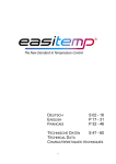
Dimensioni di Ingombro e di Foratura
Strumento
1200
Strumento
1300
A
A
Installazione con fissaggio a pannello
Avvertenze e Prescrizioni per l’Installazione a
Pannello
Oltre al regolatore vero e proprio ed alle presenti istruzioni per l’uso, l’imballo del regolatore contiene:
Prescrizioni per la categoria di installazione
II, grado di inquinamento 2, doppio isolamento.
• n° 2 staffe di fissaggio a pannello (A)
• n° 1 guarnizione di protezione per polveri e spruzzi
d’acqua (B)
•
•
•
A
•
B
•
le linee di alimentazione devono essere separate da
quelle di ingresso e uscita dei regolatori
raggruppare la strumentazione separandola dalla
parte di potenza dei relè
evitare che nello stesso quadro coesistano:
teleruttori ad alta potenza, contattori, relè; gruppi di
potenza a tiristori, in particolare a” sfasamento”;
motori, etc.
evitare la polvere, l’umidità, i gas corrosivi, le fonti di
calore
non occludere le fessure di aerazione:
la temperatura di lavoro deve rientrare nell’intervallo
0...50°C
Condizioni ambientali nominali
Montare il regolatore a pannello come illustrato in figura.
Altitudine
Temperatura
di lavoro/stoccaggio
Umidità relativa
non condensante
Fino a 2000m
0..50°C/-20...70°C
20...85%
Prima di alimentare il Regolatore, accertarsi
che la tensione di alimentazione corrisponda a quanto indicato nell’ultimo numero
della sigla di ordinazione.
B
A
Esempio:
1200/1300 – xx – xx – xx – x – 1 = 100..240Vac/dc
1200/1300 – xx – xx – xx – x – 0 = 11..27Vac/dc
7
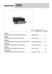
Collegamenti Elettrici
1200
PWR
Uscite
Out3 - Out4
Uscite
Out1 - Out2
Ingressi Digitali
/
Ingresso TA
Linea seriale
Ingressi
Effettuare le connessioni utilizzando sempre tipi di cavo adeguati ai limiti di tensione e corrente indicati
nella Sezione 5 – Caratteristiche Tecniche.
Se il Regolatore è equipaggiato con contatti tipo faston è necessario che questi siano di tipo protetto e
isolato.
Se è equipaggiato con contatti a vite è necessario provvedere all’ancoraggio dei cavi, almeno a coppie
Alimentazione
~PWR
~
Standard:
Opzionale:
Potenza:
100...240Vac/dc ±10%
11...27Vac/dc ±10%
max 15VA; 50/60 Hz
Ingressi
Ingresso TC
+
Termocoppie disponibili:
J, K, R, S, T
(B,E, N, L, U, G, D, C possibile inserendo una linearizzazione custom)
- Rispettare la polarità
- Per estensioni, usare cavo
compensato adatto al tipo di
TC utilizzata
Ingresso Lineare con Trasmettitore 2 fili alimentato
dallo strumento
+
VT
24V
+
Ingresso Lineare con trasmettitore 3 fili alimentato
dallo strumento
Collegare per ingresso
+
VT
24V
+
0/4..20mA
S
+
Ingresso Lineare (I)
Ingresso lineare in corrente
continua
Jumper S3 chiuso scheda
CPU
(vedi Cap. 6 -Manutenzione)
0/4..20mA, Ri = 50Ω
+
+
4..20mA
8
Ingressi
Ingresso Lineare (V)
Ingresso PTC/NTC/Pt100/JPT100
Ingresso lineare in
tensione continua
60 mV, 1V (Ri > 1MΩ)
5V, 10V (Ri > 10KΩ)
T
T
+
collegamento 2 fili
Uscite Out1, Out 2
Uscita Out 2
C
NO
Out3
+
Uscita Out 2
- Relè 5A
250Vac/30Vdc
- Relè 5A
250Vac/30Vdc
NC non disponibile se Out2
è di tipo triac
Uscite Out3, Out 4
Uscita Out 3
collegamento 3 fili
uscite ad uso generico configurabili
Uscita Out 1
NC
Jumper S2 chiuso
scheda CPU
(vedi Cap. 6 Manutenzione)
Usare fili di sezione adeguata
(min. 1mm2)
C
Triac
20...240Vac,
max. 1A ± 10%
- Logica 24V
(10V a 20mA)
-
NO +
load
~
~
uscite ad uso generico configurabili
Uscita Out 4
- Relè 5A 250Vac/30Vdc
- Logica 24V 10V a 20mA
- Continua 0...10V, 0/4...20mA
- Analogica 0...10V, 0/4...20mA
- 0/2...10V (S1-ON),
0/4...20mA (S1-OFF).
S1 é un ponticello presente
sulle schedine per uscita
continua o analogica
- Relè 5A 250Vac/30Vdc
- Logica 24V (10V a 20mA )
Out4
+
S1
Ingressi Digitali / Ingresso TA
ingressi ad uso generico configurabili
Ingressi Digitali IN1, IN2
COM
IN2
IN1
Ingressi TA, IN1
Ingressi digitali 24V 5mA
(ponticelli S1, S2 in posizione P)
o da contatto libero da tensione
(ponticelli S1, S2 in posizione
N)
Configurazione Menù
Hrd Prametro diG o di2 = +16
N
COM
- Ingresso da trasformatore
amperometrico TA 50mAac,
100Ω 50/60Hz
TA
IN1
S1 P
S2
- Ingresso digitale 24V 5mA
(ponticelli S1, S2 in posizione P)
o da contatto libero da tensione
(ponticelli S1, S2 in posizione N)
Configurazione Menù
Hrd Prametro diG o di2 = +16
N
9
S1 P
S2
Linea Seriale
Modbus 2 fili (Standard)
Modbus 4 fili / Cencal
Linea seriale isolata RS485
Linea seriale isolata RS485
+
Rx
Per configurazione Modbus 4
fili/Cencal.
GND
+
B
(data -)
Tx
A
(data +)
S1
S1
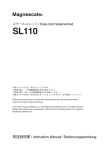
Esempio di Collegamento con Ingresso TC
Riscaldamento elettrico con gruppo statico e raffreddamento ad acqua con elettrovalvola
PWR
AUX
EV
OUT1 relé
+
OUT2 logica
10
L1
L2
3 • OPERATIVITÀ
Questa sezione illustra le funzioni e le modalità di utilizzo dei display, degli indicatori luminosi e dei pulsanti che costituiscono l’interfaccia operatore dei regolatori 1200/1300. Rappresenta quindi un requisito
essenziale per poter eseguire correttamente la programmazione e la configurazione dei regolatori.
Interfaccia operatore
ID
Simbolo
Funzione
PV : Visualizza la variabile di processo, l’identificativo dei menu,
l’identificativo dei parametri e i codici di errore
SV : Visualizza il valore di setpoint, il valore del parametro indicato in
PV e tre trattini (- - -) quando PV contiene una voce di menu
Incrementa/Decrementa il valore del parametro visualizzato in SV fino a
raggiungere il valore max/min.
Premuti in continuazione: aumenta progressivamente la velocità di incremento/decremento del valore visualizzato in SV.
Permette di navigare tra i vari menu e parametri del regolatore.
Conferma il valore del parametro esistente (o modificato tramite
e seleziona il parametro successivo.
)
Pulsante con funzione configurabile: con la configurazione standard commuta
la modalità di funzionamento del regolatore (MANUALE/AUTOMATICA).
E’ attivo solo quando il display
visualizza la variabile di processo.
(per la configurazione vedere parametro BVT nel menu KRD )
+
Conferma il valore del parametro esistente (o modificato tramite
) e seleziona il parametro precedente.
Indicatori di stato delle uscite:
OUT1 (AL1), OUT2 (Main), OUT3 (HB), OUT4
Indicatori di funzione: con la configurazione standard segnalano lo stato
di funzionamento del regolatore
Per la configurazione vedere parametro LD.1, LD.2, LD.3 nel menu KRD
L1 MAN/AUTO =
OFF (regolazione automatica)
ON (regolazione manuale)
L2
SETPOINT 1/2 = OFF (IN1= OFFSetpoint locale 1)
ON (IN1=ON Setpoint locale 2)
L3
SELFTUNING =
11
ON (Self attivato)
OFF(Self disattivato)
Note operative generali
Accensione e Funzionamento del Regolatore
Autodiagnostica
• Subito dopo l’accensione il regolatore esegue un test di autodiagnostica.
Durante il test, tutti i segmenti del display e i 7 indicatori luminosi lampeggiano.
• Se l’autodiagnostica non rileva errori il regolatore entra nello stato di normale
funzionamento (Livello 1)
• Gli errori eventualmente rilevati dall’autodiagnostica vengono memorizzati in un
registro e possono essere visualizzati con la funzione
ERR del menu INF
Normale Funzionamento
Livello 1
399
400
PV
Errori durante il
funzionamento
SV
PV Visualizza il valore della Variabile di Processo.
SV Visualizza il valore di Setpoint oppure il valore dell’Uscita di Controllo in caso
di modalità di funzionamento Manuale.
• Premendo brevemente
si possono visualizzare in sequenza sul display
PV (e all’occorrenza modificare) i valori significativi che condizionano il
funzionamento del regolatore nel Livello 1 (Setpoint, Soglie di Allarme, Uscita di
Regolazione, ecc.)
• Tenendo premuto
per 3 secondi si entra nel menu di Programmazione
/Configurazione – vedere Navigazione nei Menu del Regolatore, per ulteriori
dettagli.
• Premendo
si può incrementare/decrementare il valore del Setpoint,
fino ad ottenere il valore desiderato.
In caso di errori durante il normale funzionamento:
PV
Visualizza l’Identificativo dell’Errore.
SV
Continua a visualizzare il valore di Setpoint o dell’Uscita di Controllo.
LO
variabile di processo < limite min. di scala (param. LOS nel menu INP)
KI
variabile di processo > limite max. di scala (param. K'S nel menu INP)
SBR
sonda interrotta o valori dell’ingresso superiore ai limiti massimi
ERR
terzo filo interrotto per PT100,PTC o valori dell’ingresso inferiori ai limiti
minimi (es. per TC con collegamento errato)
Per la soluzione del problema, fare riferimento al paragrafo: Guida alla Soluzione dei Problemi nella
Sezione 6 Manutenzione.
12
Navigazione nei Menù del Regolatore
Tenere premuto
per scorrere i menu in successione e rilasciarlo quando compare il menu desiderato.
Premere
per accedere ai parametri del menu selezionato.
Tenendo premuti
+
si ritorna immediatamente al livello 1.
Visualizzazione livello 1
39.9
40.0
Menu
InF
PV
NO
SP
Setpoint locale
PV
SV
S4 ON ?
OK
SV
G FG
S P .I
PV
---
SV
Ponticello S4 sul lato saldature
della scheda CPU
Vedere Sez. 6 – Manutenzione
Configurazione
PV
---
Visualizzazione
Informazioni
SV
Setpoint 1
PV
SV
S ER
---
S P. 2
PV
Setpoint 2
I n P.
SV
0vt
Valore ingresso amperometrico
(con ingresso TA presente)
PV
SV
Comunicazione
Seriale
SV
Impostazione
Ingressi
SV
Impostazione
Uscite
PV
---
I n.2
SV
PV
PV
---
PAS
99
Password
PV
AL.I
Soglia allarme 1
(punti scala)
PV
SV
NO
A L.2
A L.3
SV
Soglia allarme 2
(punti scala)
SV
Soglia allarme 3
(punti scala)
PV
PV
PAS=99 ?
OK
Pro
Soglia allarme HB (punti scala
ingresso amperometrico)
PV
SV
0v. P
Krd
Li n
Valore uscite di regolazione in %
(+Heat / - Cool)
PV
SV
Codice
di Protezione
SV
Configurazione
Hardware
PV
---
Linearizzazione
Ingresso
PV
---
- Impostare 99 senza premere
- Per accedere a parametro PRO
premere una volta
- Per accedere al menu successivo mantenere premuto
SV
PV
---
A . Kb
SV
SV
Visualizzazione
di questo
menù solo se
Pro = 128
(*)
U. GA
(*) E’ disabilitato il ritorno a tempo a
livello 1.
PV
---
SV
Calibrazione
Utente
I parametri e i menu non significativi per una determinata configurazione NON sono visualizzati
Se i tasti
,
non sono premuti entro circa 15 secondi, la visualizzazione torna a livello 1
13
4 • CONFIGURAZIONE / PROGRAMMAZIONE
Questa sezione contiene le istruzioni necessarie per
configurare il Regolatore 1200/1300 in base alle esigenze applicative.
Esempio: Parametro H.IT nel menu (FG
h.It
4.00
Il funzionamento ottimale del Regolatore 1200/1300 nell’ambito
dell’applicazione a cui è destinato, dipende largamente dalla
corretta configurazione e programmazione dei parametri di
controllo previsti.
La flessibilità e l’elevato livello prestazionale di questi strumenti
si basa infatti su numerosi parametri programmabili direttamente dall’utente utilizzando i pulsanti del pannello di controllo,
oppure trasferibili da PC, sotto forma di file di configurazione,
attraverso l’interfaccia RS485 disponibile come opzione sui
Regolatori 1200/1300.
Tempo Integrale di riscaldamento
[0.0 ... 99.99] min
PV
SV
(valore di default)
Note Supplementari per la Consultazione delle Pagine di
Configurazione/Programmazione
Per l’impostazione di alcuni parametri particolarmente complessi è necessario consultare determinate tabelle o note esplicative di dettaglio.
Tali tabelle o note esplicative sono riportate direttamente nella
parte destra della pagina in corrispondenza del parametro in
questione.
Configurazione Easy
Per semplificare l’attività di configurazione e programmazione Note Applicative
dei Regolatori nelle applicazioni di termoregolazione più diffuLe spiegazioni dettagliate di determinate modalità di
se, che non richiedono controlli particolarmente complessi, è
funzionamento o tecniche particolari frutto della plurienprevisto un livello di configurazione semplificato (“Easy”) adatto
nale esperienza Gefran nel campo della termoregolazioalle versioni base dello strumento, con due sole uscite (Out1 –
ne sono invece riportate al termine della Sezione di
Out2).
Configurazione/Programmazione e possono rappresentare un prezioso strumento di consultazione per l’utente.
La configurazione Easy presenta essenzialmente tre menu:
Ove necessario, nei flussi di configurazione / program(FG
:
configurazione generale del Regolatore
mazione vengono forniti gli opportuni richiami alle sudINP
:
modalità di funzionamento dell’ingresso
dette Note Applicative.
0VT
:
modalità di funzionamento delle uscite
Password: PAS
che prevedono l’impostazione di un numero limitato di parameDurante lo scorrimento dei menu (tenendo premuto
), dopo
tri (massimo 13), oltre all’impostazione della soglia di Allarme
il menu 0VT, compare la scritta PAS.
AL.1 effettuabile direttamente nel livello 1.
L’accesso ai menu successivi è possibile solo se si imposta il
parametro PAS = 99, premendo
.
Configurazione Estesa
Dopo aver impostato il valore 99 premere e mantenere premuL’accesso a tutti i menu di configurazione / programmazione e
to
per accedere ai menu successivi.
a tutti i parametri disponibili per i Regolatori 1200/1300 in configurazione Estesa, permette di configurare il Regolatore nei
Codice di Protezione: PRO
minimi dettagli, per soddisfare qualsiasi esigenza applicativa.
Il parametro PRO permette di scegliere tra configurazione
“Easy” e configurazione “Estesa”, e inoltre permette di abilitare
La corretta impostazione dei parametri previsti nella
o disabilitare la visualizzazione e/o la modifica di determinati
configurazione estesa presuppone un elevato livello di
parametri. Per ulteriori dettagli fare riferimento alla descrizione
conoscenza delle problematiche e delle tecniche di
del parametro PRO nei flussi di configurazione.
termoregolazione, per cui si raccomanda di non procedere alla modifica di questi parametri, se non pienaPonticello S4 su Scheda CPU
mente consapevoli delle conseguenze che potrebbero
L’assenza del ponticello S4 sulla scheda CPU del Regolatore
derivare da una impostazione errata dei medesimi.
impedisce l’accesso a tutti i menu quando la configurazione
hardware dello strumento è tale da non richiedere la modifica
E’ responsabilità dell’utente verificare, prima della
dei parametri pre-impostati.
messa in servizio del Regolatore, la corretta impoTale ponticello viene inserito o disinserito in produzione e non
stazione dei parametri, per evitare danni a persone
deve normalmente essere modificato dall’utente finale.
o cose.
Per ulteriori informazioni, fare riferimento alla Sezione 6 Manutenzione.
In caso di dubbi o necessità di chiarimenti, si prega di
consultare il sito web www.gefran.com ed eventualmente contattare il servizio Customer Care Gefran.
Per selezionare la modalità di Configurazione Estesa, è necessario aggiungere 128 al valore del parametro PRO che compare durante lo scorrimento dei menu del Regolatore – vedere
Navigazione nei Menù del Regolatore.
Le pagine che seguono descrivono uno ad uno i vari menu del
Regolatore e riportano per ogni parametro la descrizione sintetica della funzione svolta, l’eventuale valore di default e il
campo dei valori impostabili.
14
Configurazione/Programmazione EASY
Standard per strumento con 2 uscite: OUT1 = AL1 / OUT2 = MAIN HEAT
Nella configurazione EASY, il flusso di navigazione generale riportato al termine della Sezione 3 – Operatività
risulta notevolmente semplificato, come illustrato nella figura seguente.
Visualizzazione livello 1
39.9
40.0
Menu
PV
SV
3 sec.
NO
AL.I
PV
SV
Soglia allarme 1
(punti scala)
S4 ON ?
OK
G FG
I n P.
SV
SV
Impostazione
Ingressi
SV
Impostazione
Uscite
PV
---
0vt
Configurazione
PV
---
PV
---
PAS
99
Password
PV
NO
Ponticello S4 sul lato saldature
della scheda CPU
Vedere Sez. 6 – Manutenzione
SV
PAS = 99 ?
OK
Pro
PV
---
15
SV
Codice di
Protezione
(FG
Configurazione
-Easy-
Quarto menù da configurare
Questo menù permette di configurare i parametri di regolazione in versione Easy.
G FG
PV
---
SV
S.tun
S. t v
0
1
2
3
4
5
6
7
S.tun
Abilitazione Self Tuning, Auto Tuning,
Soft Start (**)
PV
0
SV
8*
9
10*
11
12*
13
Autotuning
continuo
NO
SI
NO
SI
NO
SI
Autotuning
singola azione
WAIT
GO
WAIT
GO
WAIT
GO
Selftuning
NO
NO
SI
SI
NO
NO
Selftuning
NO
NO
SI
SI
NO
NO
Softstart
NO
NO
NO
NO
SI
SI
Softstart
NO
NO
NO
NO
SI
SI
*) sommando al valore indicato in tabella le seguenti cifre è
possibile abilitare una serie di funzioni supplementari:
+16 con passaggio automatico in GO se PV-SP > 0,5%
+32 con passaggio automatico in GO se PV-SP > 1%
+64 con passaggio automatico in GO se PV-SP > 2%
+128 con passaggio automatico in GO se PV-SP > 4%
**) Per maggiori informazioni sulle funzioni Self Tuning, Auto
Tuning, Soft Start, fare riferimento al paragrafo
Note Operative.
h.Pb
PV
1.0
h.It
SV
h.dt
Tempo Integrale di riscaldamento
[0.00 ... 99.99] min.
PV
4.00
Banda proporzionale di riscaldamento
o isteresi in regolazione ON/OFF
[0 ... 999.9] % f.s.
SV
NB.:
Se abilitato il controllo HEAT/COOL nel parametro
PV
1.00
SV
Tempo Derivativo di riscaldamento
[0.00 ... 99.99] min.
[TR nel menù KRD, si abilitano i parametri cPb ,
cIt, cdt, cPK del raffreddamento con le stesse
h.P.K
PV
100.0
KY.i
SV
PV
- 1
SV
caratteristiche di impostazione del riscaldamento.
Limite MAX potenza di riscaldamento
[0.0 ... 100.0] %
Isteresi per Allarme 1
[±999] punti scala
Sommando +32 al valore di A 1.T del menu 0VT,
il campo di impostazione è [0 … 999] sec.
Sommando +64 al valore di A 1.T del menu 0VT,
il campo di impostazione è [0 … 999] min.
16
INP
-Easy-
Impostazione Ingressi Terzo menù da configurare
I n P.
TYP
---
tYP
SV
SV
PV
0
SV
Tipo di Sonda, segnale, abilitazione
linearizzazione custom e scala ingresso
principale
Posizione Punto Decimale
per Scala Ingresso
DP.S
0
1
2
3
Lo.S
PV
0
Ki .S
SV
PV
0
Ki .L
SV
PV
1000
LoL
0
1
2
3
4
5
6
7
8
9
30
31
32
33
34
35
36
37
38
40
42
44
46
48
50
52
54
56
PV
0
dP.S
Tipo sonda
PV
SV
PV
1000
SV
Formato
xxxx
xxx.x
xx.xx (*)
x.xxx (*)
Limite MIN Scala Ingresso Principale
Valore Min..Max associato all’ingresso
selezionato con il parametro TYP
Limite MAX Scala Ingresso Principale
Valore Min..Max associato all’ingresso
selezionato con il parametro TYP
Limite Inferiore impostabilità SP e
allarmi assoluti LO.S ... KI.S
Limite Superiore impostabilità SP e
allarmi assoluti LO.S ... KI.S
(*) non disponibile per sonde TC, RTD, PTC, NTC.
Senza punto
Dec.
DP.S = 0
Sensore:
TC
TC J °C
0/1000
TC J °F
32/1832
TC K °C
0/1300
TC K °F
32/2372
TC R °C
0/1750
TC R °F
32/3182
TC S °C
0/1750
TC S °F
32/3182
TC T °C
-200/400
TC T °F
-328/752
PT100 °C
-200/850
PT100 °F
-328/1562
JPT100 °C
-200/600
JPT100 °F
-328/1112
PTC °C
-55/120
PTC °F
-67/248
NTC °C
-10/70
NTC °F
14/158
0...60 mV
-1999/9999
12...60 mV
-1999/9999
0...20 mA
-1999/9999
4...20 mA
-1999/9999
0...10 V
-1999/9999
2...10 V
-1999/9999
0...5 V
-1999/9999
1...5 V
-1999/9999
0...1 V
-1999/9999
200 mV...1 V
-1999/9999
Con punto
Dec.
DP.S = 1
0.0/999.9
32.0/999.9
0.0/999.9
32.0/999.9
0.0/999.9
32.0/999.9
0.0/999.9
32.0/999.9
-199.9/400.0
-199.9/752.0
-199.9/850.0
-199.9/999.9
-199.9/600.0
-199.9/999.9
-55.0/120.0
-67.0/248.0
-10.0/70.0
14.0/158.0
-199.9/999.9
-199.9/999.9
-199.9/999.9
-199.9/999.9
-199.9/999.9
-199.9/999.9
-199.9/999.9
-199.9/999.9
-199.9/999.9
-199.9/999.9
Linearizzazione CUSTOM:
la segnalazione L0 si ha quando la variabile assume valori
inferiori al parametro LO.S o al valore minimo di calibrazione.
la segnalazione KI si ha quando la variabile assume valori
superiori al parametro K'.S o al valore massimo di calibrazione.
Errore massimo di Non Linearità per Termocoppie (TC),
Termoresistenze (Pt100) e Termistori (PTC, NTC).
L’errore è calcolato come scostamento dal valore teorico con
riferimento in % al valore di fondo scala, espresso in gradi
Celsius (°C)
Tipo Sonda
Termocoppie
Sensore
Errore
TC tipo J, K
< 0,2 % f.s.
TC tipo S, R
con scala 0..1750 °C: < 0,2 % f.s.
(t > 300 °C); per altre scale: < 0,5 % f.s.
TC tipo T
Termistori
Termoresistenze
< 0,2 % f.s. (t > -150 °C)
NTC
< 0,5 % f.s.
JPT100 / PTC
< 0,2 % f.s.
Pt100
con scala -200..850 °C: accur. migliore
dello 0,2 % f.s.
17
0VT
Impostazione Uscite
-Easy-
Secondo menù da configurare
Questo menù permette di configurare il tipo di Allarme 1 e il tempo di ciclo dell’Uscita 2.
0vt
PV
A1.T
---
AI.t
SV
Diretto
(di massima)
Inverso
Assoluto/Relativo
(di minima) al Setpoint attivo
Normale
Simmetrico
(finestra)
PV
0
Tipo Allarme 1
NB.:
Se abilitati più allarmi la tabella della
funzionalità vale anche per A2t, A3t.
SV
0
1
2
3
4
5
6
7
Diretto
Inverso
Diretto
Inverso
Diretto
Inverso
Diretto
Inverso
Assoluto
Assoluto
Relativo
Relativo
Assoluto
Assoluto
Relativo
Relativo
Normale
Normale
Normale
Normale
Simmetrico
Simmetrico
Simmetrico
Simmetrico
sommando al valore indicato in tabella le seguenti cifre è
possibile abilitare una serie di funzioni supplementari:
+8: disabilitazione accensione fino alla prima
intercettazione.
+16: abilitazione memoria allarme.
+32: KY.1 menu [FG = tempo di ritardo attivazione allarme
([0..999] sec. (escluso assoluto simmetrico)
+64: KY.1 menu [FG = tempo di ritardo attivazione allarme
([0..999] min. (escluso assoluto simmetrico)
rL. 1
PV
2
SV
RL.1; RL.2
RL.3; RL.4
0
1
2
3
4
5
6
7
8
9
10
11
12
13
14
15
16
OUT 1
Attribuzione segnale di riferimento
NB.:
Se presenti più uscite (rL2, rL3, rL4)
fare riferimento alla presente tabella.
Funzione
HEAT (uscita di controllo riscaldamento)
COOL (uscita di controllo raffreddamento)
AL1 – allarme 1
AL2 – allarme 2
AL3 – allarme 3
AL. HB – allarme HB
LBA – allarme LBA
IN – ripetizione ingresso logico 1
Ripetizione tasto but (se BVT menu KRD = 8)
AL1 or AL2
AL1 or AL2 or AL3
AL1 And AL2
AL1 and AL2 and AL3
AL1 or AL. HB
AL1 or AL2 or AL. HB
AL1 and AL. HB
AL1 and AL2 and AL. HB
Sommare +32 ai valori indicati in tabella per ottenere in uscita il
livello logico negato, eccetto codici 0..1 con uscita continua
64 *
65 *
RL.2 HEAT: uscita di controllo riscaldamento con
tempo di ciclo veloce (0.1 ... 20.0 sec.)
RL.3 HEAT: uscita continua 2 – 10 V
RL.2 COOL: uscita di controllo raffreddamento con
tempo di ciclo veloce (0.1 ... 20.0 sec.)
RL.3 COOL: uscita continua 2 – 10 V
*) solo per RL.3 o RL.2 se OUT3 continua NON presente
Gt.2
PV
20
SV
Tempo di Ciclo OUT 2 (HEAT o COOL)
[1 ... 200] sec.
NB.:
le stesse caratteristiche di impostazione
valgono anche per Ct1, Ct3, Ct4.
18
PRO
-Easy-
Codice di Protezione
Questo menù permette di abilitare o disabilitare la visualizzazione e/o modifica di determinati parametri e di accedere alla configurazione estesa.
P ro
PRO
0
1
2
PV
0
SV
Visualizzazione
SP, allarmi
SP, allarmi
SP
Modifica
SP, allarmi
SP
sommando al valore indicato in tabella le seguenti cifre
è possibile attivare una serie di funzioni supplementari:
+4: disabilitazione INP, 0VT
+8: disabilitazione [FG
+128: abilitazione alla visualizzazione di tutti i parametri e menù.
19
CONFIGURAZIONE / PROGRAMMAZIONE ESTESA (Cenni)
Questa sezione contiene alcuni cenni sulle principali funzioni offerte dalla Configurazione Estesa.
Configurazione Hardware
Questo menù permette di configurare i parametri hardware del Regolatore.
Di seguito come settare alcune delle principali funzioni offerte
KRD
Krd
[TR
0
1
2
3
4
5
6
7
8
9
10
11
12
13
14
PV
---
G tr
SV
PV
6
Tipo di controllo
SV
Tipo di Controllo
P caldo
P freddo
P caldo / freddo
PI caldo
PI freddo
PI caldo / freddo
PID caldo
PID freddo
PID caldo / freddo
ON – OFF caldo
ON – OFF freddo
ON – OFF caldo / freddo
PID caldo + ON – OFF freddo
ON – OFF caldo + PID freddo
PID caldo + freddo con Guadagno Relativo
(vedere “Note Applicative”)
sommando al valore indicato in tabella le seguenti cifre è possibile selezionare il tempo di campionamento
(sample) dell’azione derivativa:
+0:
sample 1 sec.
+16:
sample 4 sec.
+32:
sample 8 sec.
+64:
sample 240 msec.
NOTA: Nel controllo ON – OFF, l’allarme LBA non è abilitato
A L. n
Selezione Numero di Allarmi Abilitati
PV
i
AL.N
0
1
2
3
4
5
6
7
SV
Allarme 1
disabilitato
abilitato
disabilitato
abilitato
disabilitato
abilitato
disabilitato
abilitato
Allarme 2
disabilitato
disabilitato
abilitato
abilitato
disabilitato
disabilitato
abilitato
abilitato
Allarme 3
disabilitato
disabilitato
disabilitato
disabilitato
abilitato
abilitato
abilitato
abilitato
sommando al valore indicato in tabella le seguenti cifre è possibile abilitare una serie di funzioni supplementari:
+8:
abilitazione allarme HB
+16:
abilitazione allarme LBA
b t
Funzione del Tasto M/A
PV
n
0
BVT
0
1
2
3
4
5
6
7
8
SV
Funzione
disabilitato (nessuna funzione)
MAN / AUTO regolatore
LOC / REM
HOLD
Reset memoria allarmi
Selezione SP1 / SP2
Start / Stop Self Tuning
Start / Stop Auto Tuning
Set / Reset uscite OUT 1 ... OUT 4
sommando +16 al valore indicato in tabella, si disabilita la funzione di “back menu” (combinazione di
tasti
+
)
Ld.1
PV
1
LD.1
LD.2
LD.3
0
1
2
3
4
5
6
7
8
9
10
11
Funzione LED 1
SV
Ld.2
10
SV
Ld.3
20
SV
PV
PV
Funzione LED 2
Funzione LED 3
Funzione
nessuna funzione
MAN / AUTO regolatore
LOC / REM
HOLD
Self Tuning attivo
Auto Tuning attivo
Ripetizione IN 1
Abilitazione comunicazione seriale
Errore
Softstart in esecuzione
Indicazione SP1 ... SP2
Gradiente di setpoint in esecuzione
sommando +16 al valore indicato in tabella, il LED lampeggia se attivo
20
(FG
Configurazione
Quarto menù da configurare
Questo menù permette di configurare i vari parametri di regolazione.
G FG
PV
---
S. t v
PV
SV
PV
1.0
h.It
SV
h.P.K
SV
SV
h. P.L
0.0
PV
SV
PV
0
c. S P
0
c. P b
1.0
SV
SetPoint di raffreddamento relativo al
set di riscaldamento
[±25.0] % f.s.
SV
Banda proporzionale di raffreddamento
o isteresi in regolazione ON/OFF
[0 ... 999.9] % f.s.
SV
Tempo Integrale di raffreddamento
[0.00 ... 99.99] min.
SV
Tempo Derivativo di raffreddamento
[0.00 ... 99.99] min.
SV
Limite MAX potenza di raffreddamento
[0.0 ... 100.0] %
PV
c. I t
4.00
PV
c. d t
1.00
PV
c. P.K
PV
100,0
Limite MIN potenza di riscaldamento
(non disponibile per doppia azione
caldo/freddo)
[0.0 ... 100.0] %
Selftuning
NO
NO
SI
SI
NO
NO
Selftuning
NO
NO
SI
SI
NO
NO
Softstart
NO
NO
NO
NO
SI
SI
Softstart
NO
NO
NO
NO
SI
SI
**) Per maggiori informazioni sulle funzioni Self Tuning, Auto
Tuning, Soft Start, fare riferimento al paragrafo
Note Operative.
[ME
0
1
2
SV
PV
Autotuning
continuo
NO
SI
NO
SI
NO
SI
Autotuning
singola azione
WAIT
GO
WAIT
GO
WAIT
GO
*) sommando al valore indicato in tabella le seguenti cifre è
possibile abilitare una serie di funzioni supplementari:
+16 con passaggio automatico in GO se PV-SP > 0,5%
+32 con passaggio automatico in GO se PV-SP > 1%
+64 con passaggio automatico in GO se PV-SP > 2%
+128 con passaggio automatico in GO se PV-SP > 4%
Fluido di raffreddamento
[0 ... 2]
U
G. E
Tempo Derivativo di riscaldamento
[0.00 ... 99.99] min.
Limite MAX potenza di riscaldamento
[0.0 ... 100.0] %
PV
100.0
8*
9
10*
11
12*
13
SV
PV
1.00
Banda proporzionale di riscaldamento
o isteresi in regolazione ON/OFF
[0 ... 999.9] % f.s.
Tempo Integrale di riscaldamento
[0.00 ... 99.99] min.
PV
4.00
h.dt
0
1
2
3
4
5
6
7
S.tun
Abilitazione Self Tuning, Auto Tuning,
Soft Start (**)
0
h.Pb
S.tun
SV
Tipo
ARIA
ACQUA
OLIO
Guadagno Relativo (rG)
(vedere paragrafo “Note Applicative”)
1
0,8
0,4
Parametri a sola lettura (read only) se è abilitata la
tipologia di controllo Caldo/Freddo
(parametro CTR = 14 nel menu HRD)
A
21
[gfg]
A
c. P.L
PV
0.0
SV
Reset Manuale
rS t
PV
0
SV
[-999 ... +999] punti scala
Potenza di Reset
P. rS
PV
0.0
A. rS
SV
[-100.0 ... +100.0] %
Antireset
PV
0
F Fd
0.0
SV
SoF
0.0
[0 ... 9999] punti scala
Feed forward
PV
SV
[-100.0 ... +100.0] %
Tempo di Soft Start
PV
KY.i
Limite MIN potenza di raffreddamento
(non disponibile per doppia azione caldo/freddo)
[0.0 ... 100.0] %
SV
[0.0 ... 500.0] min
Isteresi per Allarme 1
Sommando +32 al valore del parametro A1.T del menu
0VT, il campo di impostazione è [0 … 999] sec.
Sommando +64 al valore del parametro A1.T del menu
0VT, il campo di impostazione è [0 … 999] min.
PV
- 1
[±999] punti scala
SV
KY.2
- 1
Isteresi per Allarme 2
Sommando +32 al valore del parametro A2.T del menu
0VT, il campo di impostazione è [0 … 999] sec.
Sommando +64 al valore del parametro A2.T del menu
0VT, il campo di impostazione è [0 … 999] min.
PV
KY.3
- 1
[±999] punti scala
SV
Isteresi per Allarme 3
Sommando +32 al valore del parametro A3.T del menu
0VT, il campo di impostazione è [0 … 999] sec.
Sommando +64 al valore del parametro A3.T del menu
0VT, il campo di impostazione è [0 … 999] min.
PV
Kb.t
30
SV
[±999] punti scala
Tempo di attesa intervento allarme HB
PV
Lb.t
SV
Il valore deve essere maggiore del tempo di ciclo dell’uscita cui è associato l’allarme HB
[0 ... 999] sec.
Tempo di attesa intervento allarme LBA
PV
0
Lb.P
25.0
SV
[0.0 ... 500.0] min.
Limitazione della potenza fornita in condizione di
allarme LBA
PV
FA.P
0.0
SV
Se l’allarme LBA è attivo, esso può essere annullato
premendo i tasti
+
quando sul display è visualizzato il valore dell’uscita di regolazione (OutP) oppure
commutando in modo Manuale
Potenza di Fault Action (fornita in condizioni di
sonda guasta)
PV
G.S P
0.0
[-100.0 ... +100.0] %.
Se impostato a “0”, l’allarme LBA è disabilitato
Se l’allarme LBA è attivo, esso può essere annullato
premendo i tasti
+
quando sul display è
visualizzato il valore dell’uscita di regolazione (OutP)
oppure commutando in modo Manuale
SV
[-100.0 ... +100.0] % ON / OFF
Gradiente di Set (vedere paragrafo “Note
Applicative”)
PV
SV
Unità di misura digit / sec : sommando + 2
al valore del parametro SP.R menu INP
[0.0 ... 999.9] digit/min
22
SEr
Comunicazione Seriale
Quinto menù da configurare
Questo menù permette di configurare i vari parametri che regolano la comunicazione seriale tra regolatore e
supervisore.
S ER
PV
---
SV
Codice Identificazione Strumento
G od
PV
1
SV
[0 ... 247]
Protocollo Interfaccia Seriale
Sr.P
PV
1
SV
[0 ... 1]
Selezione Baudrate
n
bA.
PV
4
SV
[0 ... 4]
Selezione Parità
PA r
PV
0
SV
[0 ... 2]
SR.P
0
1
Protocollo Seriale
CENCAL Gefran
MODBUS RTU
BAV
0
1
2
3
4
Baudrate
1200
2400
4800
9600
19200
PAR
0
1
2
Parità
Nessuna parità (No Parity)
Dispari (Odd)
Pari (Even)
Ingressi Strumento Virtuale
S.I n
24
Ingressi
Bit
PV
SV
[0 ... 63]
IN2
5
IN1
4
PV
3
AL3
2
AL2
1
AL1
0
Es.
0
1
1
0
0
0
Per gestire via linea seriale gli ingressi PV e IN1, assegnare a S.IN il valore 24
Uscite Strumento Virtuale
S. 0
Uscite
Bit
PV
n
19
SV
[0 ... 31]
OUTW
4
OUT4
3
OUT3 OUT2
2
1
OUT1
0
Es.
1
0
0
1
1
Per gestire via linea seriale le uscite OUT1, 2 e W,
assegnare a S.0V il valore 19
Interfaccia Utente Strumento Virtuale
S. U.I
Interf LED KEYB DISL DISH LED LED LED LED
1/2/3
OUT4 OUT3 OUT2 OUT1
PV
80
SV
[0 ... 255]
Bit
7
6
5
4
3
2
1
0
Es 0
1
0
1
0
0
0
0
Volendo gestire via linea seriale gli elementi di interfaccia
KEYB e DISH, assegnare a S.U.I il valore 80
23
I n P Impostazione Ingressi
Terzo menù da configurare
Questo menù permette di configurare i parametri per i segnali di ingresso del Regolatore.
I n P.
PV
---
SP.R
0
1
SV
Definizione tipo Set Remoto
S P. r
PV
0
tYP
0
1
2
3
4
5
6
7
8
9
28
29
30
31
32
33
34
35
36
37
38
39
40
41
SV
[0 ... 1]
Sommando +2 al valore indicato in tabella, il Gradiente di
Set (parametro G.SP del menu [FG) è espresso in digit/sec.
Tipo di Sonda, segnale, abilitazione linearizzazione custom e scala ingresso principale
PV
0
TYP
Tipo Set Remoto, Assoluto / Relativo
Digitale (da linea seriale) Assoluto
Digitale (da linea seriale) Relativo set SP o SP1 o SP2
SV
Tipo sonda
Sensore:
TC J °C
TC J °F
TC K °C
TC K °F
TC R °C
TC R °F
TC S °C
TC S °F
TC T °C
TC T °F
TC
TC
PT100 °C
PT100 °F
JPT100 °C
JPT100 °F
PTC °C
PTC °F
NTC °C
NTC °F
0...60 mV
0...60 mV
12...60 mV
12...60 mV
Senza punto Dec.
TC
0/1000
32/1832
0/1300
32/2372
0/1750
32/3182
0/1750
32/3182
-200/400
-328/752
CUSTOM
CUSTOM
-200/850
-328/1562
-200/600
-328/1112
-55/120
-67/248
-10/70
14/158
-1999/9999
Linear. custom
-1999/9999
Linear. custom
Con punto Dec. TYP
0.0/999.9
32.0/999.9
0.0/999.9
32.0/999.9
0.0/999.9
32.0/999.9
0.0/999.9
32.0/999.9
-199.9/400.0
-199.9/752.0
CUSTOM
CUSTOM
-199.9/850.0
-199.9/999.9
-199.9/600.0
-199.9/999.9
-55.0/120.0
-67.0/248.0
-10.0/70.0
14.0/158.0
-199.9/999.9
Linear. custom
-199.9/999.9
Linear. custom
42
43
44
45
46
47
48
49
50
51
52
53
54
55
56
57
58
59
60
61
62
63
64
Tipo sonda
Senza punto Dec.
Sensore:
TC
0...20 mA
-1999/9999
0...20 mA
Linear. custom
4...20 mA
-1999/9999
4...20 mA
Linear. custom
0...10 V
-1999/9999
0...10 V
Linear. custom
2...10 V
-1999/9999
2...10 V
Linear. custom
0...5 V
-1999/9999
0...5 V
Linear. custom
1...5 V
-1999/9999
1...5 V
Linear. custom
0...1 V
-1999/9999
0...1 V
Linear. custom
200 mV...1 V
-1999/9999
200 mV...1 V
Linear. custom
Cust. 10V-20mA -1999/9999
Cust. 10V-20mA Linear. custom
Cust. 60 mV
-1999/9999
Cust. 60 mV
Linear. custom
PT100 – JPT
CUSTOM
PTC
CUSTOM
NTC
CUSTOM
Con punto Dec.
-199.9/999.9
Linear. custom
-199.9/999.9
Linear. custom
-199.9/999.9
Linear. custom
-199.9/999.9
Linear. custom
-199.9/999.9
Linear. custom
-199.9/999.9
Linear. custom
-199.9/999.9
Linear. custom
-199.9/999.9
Linear. custom
-199.9/999.9
Linear. custom
-199.9/999.9
Linear. custom
CUSTOM
CUSTOM
CUSTOM
Linearizzazione CUSTOM: la segnalazione L0 si ha quando la variabile assume valori inferiori al parametro LO.S o al valore
minimo di calibrazione. la segnalazione KI si ha quando la variabile assume valori superiori al
parametro KiS o al valore massimo di calibrazione
Errore massimo di Non Linearità per Termocoppie (TC), Termoresistenze (Pt100) e Termistori (PTC, NTC). L’errore è calcolato
come scostamento dal valore teorico con riferimento in % al valore di fondo scala, espresso in gradi Celsius (°C)
Tipo Sonda
Termocoppie
Termistori
Termoresistenze
FLt
0.1
Filtro Digitale Ingresso
[0.0 ... 20.0] sec
PV
F Ld
0.5
Sensore
Errore
TC tipo J, K
< 0,2 % f.s.
TC tipo S, R
con scala 0..1750 °C: < 0,2 % f.s. (t > 300 °C); per altre scale: < 0,5 % f.s.
TC tipo T
< 0,2 % f.s. (t > -150 °C)
Utilizzando una Linearizzazione Custom:
TC tipo E, N, L
< 0,2 % f.s.; tipo E scala 100..750 °C; tipo N scala 0..1300 °C; tipo L scala 0..600 °C
TC tipo B
con scala 44..1800 °C: < 0,5 % f.s. (t > 300 °C)
TC tipo U
con scala -200..400 °C: < 0,2 % f.s. (t > -100 C°)
TC tipo G
< 0,2 % f.s. (t > 300 °C)
TC tipo D
< 0,2 % f.s. (t > 200 °C
TC tipo C
con scala 0..2300 °C: < 0,2 % f.s.
NTC
< 0,5 % f.s.
JPT100 / PTC
< 0,2 % f.s.
Pt100
con scala -200..850 °C: accur. migliore dello 0,2 % f.s.
Se impostato a “0”, viene escluso il filtro di media sul valore
campionato
SV
PV
SV
Filtro Digitale sulla Visualizzazione
dell’Ingresso
[0 ... 9.9] punti scala
24
InP
dP.S
0
DP.S
0
1
2
3
Posizione Punto Decimale per Scala
Ingresso
PV
SV
Formato
xxxx
xxx.x
xx.xx (*)
x.xxx (*)
(*) NON disponibile per sonde TC, RTD, PTC, NTC
Lo.S
PV
0
Ki .S
PV
1000
o FS
Limite MIN Scala Ingresso Principale
Valore Min..Max associato all’ingresso selezionato con il
parametro TYP
SV
Limite MAX Scala Ingresso Principale
Valore Min..Max associato all’ingresso selezionato con il
parametro TYP
SV
Offset Correzione Ingresso Principale
PV
0
Ft. 2
0.1
SV
[-999 ... +999] punti scala
Filtro Digitale Ingresso Ausiliario
PV
LS. 2
0.0
SV
[0.0 ... 20.0] sec.
Limite MIN Scala Ingresso Ausiliario
PV
KS. 2
100.0
SV
[0.0 ... 999.9]
Limite MAX Scala Ingresso Ausiliario
PV
oF. 2
0.0
SV
[0.0 ... 999.9]
Offset Correzione Ingresso Ausiliario
PV
LoL
[-99.9 ... +99.9] punti scala
Limite Inferiore impostabilità SP e allarmi assoluti
PV
0
Ki .L
SV
SV
LO.S ... KI.S
Limite Superiore impostabilità SP e allarmi assoluti
PV
1000
SV
LO.S ... KI.S
25
0 V T Impostazione Uscite
Secondo menù da configurare
Questo menù permette di configurare i parametri delle uscite del Regolatore.
0vt
PV
---
Ai. r
SV
PV
0
A2. r
Selezione grandezze di riferimento
Allarme 3
SV
A1.T
A2.T
A3.T
AI.t
PV
0
A2. t
Tipo Allarme 1
SV
PV
0
A3. t
Kb. F
Tipo Allarme 2
SV
Diretto
(di massima)
Inverso (di minima)
0
1
2
3
4
5
6
7
Diretto
Inverso
Diretto
Inverso
Diretto
Inverso
Diretto
Inverso
PV
Tipo Allarme 3
Funzionalità Allarme HB
PV
4
+64:
SV
Assoluto/Relativo
al Setpoint attivo
Assoluto
Assoluto
Relativo
Relativo
Assoluto
Assoluto
Relativo
Relativo
Normale
Simmetrico
(finestra)
Normale
Normale
Normale
Normale
Simmetrico
Simmetrico
Simmetrico
Simmetrico
sommando al valore indicato in tabella le seguenti cifre è possibile
abilitare una serie di funzioni supplementari:
+8:
+16:
+32:
0
Soglia di Riferimento
AL
AL solo assoluto
AL solo relativo e riferito
a SP
(con funzione MultiSet)
SV
PV
0
Variabile da Comparare
PV (variabile di processo)
SV (setpoint attivo)
PV (variabile di processo)
Selezione grandezze di
riferimento Allarme 2
PV
0
A3. r
SV
A 1.R
A2.R
A3.R
0
1
2
Selezione grandezze di riferimento
Allarme 1
KB.F
0
SV
1
2
3
7
disabilitazione accensione fino alla prima intercettazione.
abilitazione memoria allarme.
KY.1 (2 / 3 ) menu [FG = tempo di ritardo attivazione allarme
[0..999] sec. (escluso assoluto simmetrico)
KY.1 (2 / 3 ) menu [FG = tempo di ritardo attivazione allarme
[0..999] min. (escluso assoluto simmetrico)
Funzionalità
Uscita relè, logica: allarme attivo ad un valore della
corrente di carico inferiore alla soglia impostata nel
tempo di ON delll’uscita di controllo
Uscita relè, logica: allarme attivo ad un valore della
corrente di carico superiore alla soglia impostata nel
tempo di OFF delll’uscita di controllo
Allarme attivo se una delle funzioni 0 e 1 è attiva
(OR logico) (*)
Allarme continuo di riscaldamento (**)
Allarme continuo di raffreddamento (**)
sommando al valore indicato in tabella le seguenti cifre è possibile abilitare
una serie di funzioni supplementari:
+0:
associato all’uscita OUT1 (solo per KB.F = 0,1,2).
+4:
associato all’uscita OUT2 (solo per KB.F = 0,1,2).
+8:
associato all’uscita OUT3 (solo per KB.F = 0,1,2).
+12:
associato all’uscita OUT4 (solo per KB.F = 0,1,2).
+16:
allarme HB inverso.
NOTA: L’allarme HB viene disabilitato se associato ad un’uscita di tipo
veloce (eccetto codici 3 e 7)
*) La soglia minima è impostata uguale al 12% del f.s. amperometrico
**)Come tipo 0 senza riferimento al tempo di ciclo
26
RL.1; RL.2
RL.3; RL.4
0
1
2
3
4
5
6
7
8
9
10
11
12
13
14
15
16
0VT
rL. 1
OUT 1
Attribuzione segnale di riferimento
PV
2
rL. 2
SV
PV
0
rL. 3
SV
PV
3
SV
OUT 2
Attribuzione segnale di riferimento
OUT 3
Attribuzione segnale di riferimento
Funzione
HEAT (uscita di controllo riscaldamento)
COOL (uscita di controllo raffreddamento)
AL1 – allarme 1
AL2 – allarme 2
AL3 – allarme 3
AL. HB – allarme HB
LBA – allarme LBA
IN – ripetizione ingresso logico 1
Ripetizione tasto but (se BVT menu KRD = 8)
AL1 or AL2
AL1 or AL2 or AL3
AL1 And AL2
AL1 and AL2 and AL3
AL1 or AL. HB
AL1 or AL2 or AL. HB
AL1 and AL. HB
AL1 and AL2 and AL. HB
Sommare +32 ai valori indicati in tabella per ottenere in uscita il
livello logico negato, eccetto codici 0..1 con uscita continua
rL. 4
PV
4
G t.1
20
SV
OUT 4
Attribuzione segnale di riferimento
64 *
65 *
Tempo di Ciclo OUT 1 (HEAT o COOL)
PV
SV
[1 ... 200] sec.
RL.2 HEAT: uscita di controllo riscaldamento con
tempo di ciclo veloce (0.1 ... 20.0 sec.)
RL.3 HEAT: uscita continua 2 – 10 V
RL.2 COOL: uscita di controllo raffreddamento con
tempo di ciclo veloce (0.1 ... 20.0 sec.)
RL.3 COOL: uscita continua 2 – 10 V
*) solo per RL.3 o RL.2 se OUT3 continua NON presente
Gt.2
Tempo di Ciclo OUT 2 (HEAT o COOL)
PV
20
SV
G t.3
20
[1 ... 200] sec. ( [0.1 ... 20.0] sec.)
Tempo di Ciclo OUT 3 (HEAT o COOL)
PV
G t.4
20
SV
0,1 sec. se OUT3 è uscita di tipo continua, [T.3 non compare
in configurazione
[1 ... 200] sec.
Tempo di Ciclo OUT 4 (HEAT o COOL)
PV
rE l
PV
0
A n.o
SV
PV
0
L. An
SV
SV
[1 ... 200] sec.
REL
0
1
2
3
4
5
6
7
Fault Action (definizione stato in caso di
sonda guasta) Err, Sbr
OUT W
Attribuzione segnale o valore di riferimento
MIN scala uscita di ripetizione analogica
PV
0
K. An
1000
SV
Allarme 2
OFF
OFF
ON
ON
OFF
OFF
ON
ON
Allarme 3
OFF
OFF
OFF
OFF
ON
ON
ON
ON
Grandezza di riferimento
PV – Variabile di processo
SSP – Setpoint attivo
SP – Setpoint locale
–
Deviazione (SSP – PV)
HEAT (*)
COOL (*)
AL1 (soglia)
AL2 (soglia)
AL3 (soglia)
–
Valore acquisito da linea seriale (*)
Sommando 16 al codice 0, se l’ingresso è in condizione di
errore Err – Sbr l’uscita assume il minimo valore di trimming
*) – limiti di scala NON impostabili
– uscita ritrasmessa Non disponibile con tipo di controllo
ON/OFF
[-1999 ... 9999]
MAX scala uscita di ripetizione analogica
PV
SV
AN.O
0
1
2
3
4
5
6
7
8
9
10
11
Allarme 1
OFF
ON
OFF
ON
OFF
ON
OFF
ON
[-1999 ... 9999]
27
PRO
Codice di Protezione
Questo menù permette di abilitare/disabilitare la visualizzazione e/o modifica di determinati parametri e di accedere alla configurazione Easy. (Per l’accesso a questo menù fare riferimento alla sezione “Navigazione nei menù del
regolatore”)
P ro
PRO
0
1
2
PV
0
SV
Visualizzazione
SP, IN2, allarmi, 0VP, INF
SP, IN2, allarmi, 0VP, INF
SP, IN2, 0VP, INF
Modifica
SP, allarmi
SP
sommando al valore indicato in tabella le seguenti cifre è
possibile abilitare una serie di funzioni supplementari:
+4:
disabilitazione INP, 0VT
+8:
disabilitazione [FG, SER
+16: disabilitazione “accensione – spegnimento” software
+32: disabilitazione memorizzazione potenza manuale.
+64: disabilitazione modifica valore potenza manuale.
+128: abilitazione alla visualizzazione di tutti i
parametri e menù.
NOTA: 0VP e INF visualizzati solo con configurazione
estesa abilitata
KRD
Configurazione Hardware
Primo menù da configurare
Questo menù permette di configurare i parametri hardware del Regolatore. (Per l’accesso a questo menù fare riferimento alla sezione “Navigazione nei menù del regolatore”)
Krd
PV
---
SV
KD. 1
K d.1
PV
0
G tr
SV
PV
6
0
1
2
3
4
5
6
7
Abilitazione MultiSet, stato led e
strumento virtuale
[TR
0
1
2
3
4
5
6
7
8
9
10
11
12
13
14
Tipo di controllo
SV
MultiSet
(2SP)
Stato LED
invertiti
Gestione Strumento
Virtuale via Seriale
X
X
X
X
X
X
X
X
X
X
X
X
Tipo di Controllo
P caldo
P freddo
P caldo / freddo
PI caldo
PI freddo
PI caldo / freddo
PID caldo
PID freddo
PID caldo / freddo
ON – OFF caldo
ON – OFF freddo
ON – OFF caldo / freddo
PID caldo + ON – OFF freddo
ON – OFF caldo + PID freddo
PID caldo + freddo con Guadagno Relativo
(vedere “Note Applicative”)
sommando al valore indicato in tabella le seguenti cifre è possibile selezionare il tempo di campionamento (sample) dell’azione derivativa:
+0:
sample 1 sec.
+16:
sample 4 sec.
+32:
sample 8 sec.
+64:
sample 240 msec.
NOTA:
28
Nel controllo ON – OFF, l’allarme LBA non è abilitato
KRD
A L. n
Selezione Numero di Allarmi Abilitati
PV
i
AL.N
0
1
2
3
4
5
6
7
SV
Allarme 1
disabilitato
abilitato
disabilitato
abilitato
disabilitato
abilitato
disabilitato
abilitato
Allarme 2
disabilitato
disabilitato
abilitato
abilitato
disabilitato
disabilitato
abilitato
abilitato
Allarme 3
disabilitato
disabilitato
disabilitato
disabilitato
abilitato
abilitato
abilitato
abilitato
sommando al valore indicato in tabella le seguenti cifre è
possibile abilitare una serie di funzioni supplementari:
+8:
abilitazione allarme HB
+16:
abilitazione allarme LBA
b t
Funzione del Tasto M/A
PV
n
0
BVT
0
1
2
3
4
5
6
7
8
SV
Funzione
disabilitato (nessuna funzione)
MAN / AUTO regolatore
LOC / REM
HOLD
Reset memoria allarmi
Selezione SP1 / SP2
Start / Stop Self Tuning
Start / Stop Auto Tuning
Set / Reset uscite OUT 1 ... OUT 4
sommando +16 al valore indicato in tabella, si disabilita la
funzione di “back menu” (combinazione di tasti
+
)
i
d G
0
i
d 2
SV
PV
0
D ,G; D ,2
0
1
2
3
4
5
6
7
8
9
Funzione Ingresso Digitale 1 (0 ... 53)
PV
Funzione Ingresso Digitale 2 (0 ... 53)
SV
Funzione
Ingresso disabilitato (nessuna funzione)
MAN / AUTO regolatore
LOC / REM
HOLD
Reset memoria allarmi
Selezione SP1 / SP2
Spegnimento / Accensione software
Blocco Tasto
Start / Stop Self Tuning
Start / Stop Auto Tuning
sommando al valore indicato in tabella le seguenti cifre è
possibile abilitare una serie di funzioni supplementari:
+16:
ingresso in logica negata (NPN)
+32:
forzatura allo stato logico 0 (OFF)
+48:
forzatura allo stato logico 1 (ON)
S
d P
0
Ld.1
DSP
0
1
2
3
PV
SV
PV
1
Funzione del Display SV
LD. 1
LD.2
LD.3
0
1
2
3
4
5
6
7
8
9
10
11
Funzione LED 1
SV
Ld.2
10
SV
Ld.3
20
SV
PV
PV
Funzione LED 2
Funzione LED 3
Funzione
SSP – setpoint attivo
InP.2 – Ingresso ausiliario
Valore uscita di regolazione
Deviazione (SSP – PV)
Funzione
nessuna funzione
MAN / AUTO regolatore
LOC / REM
HOLD
Self Tuning attivo
Auto Tuning attivo
Ripetizione IN 1
Abilitazione comunicazione seriale
Errore
Softstart in esecuzione
Indicazione SP1 ... SP2
Gradiente di setpoint in esecuzione
sommando +16 al valore indicato in tabella, il LED lampeggia
se attivo
29
L'N
Linearizzazione Ingresso
Questo menù permette di eseguire la linearizzazione custom per l’ingresso principale.
Li n
PV
---
5. 00
SV
PV
---
SV
Passo 0 (valore di inizio scala)
Limiti di visualizzazione del display:
[-1999 ... 9999]
..........
5. 32
---
5. 33
SV
Passo 33
mV inizio scala
PV
---
5. 34
SV
Passo 32 (valore di fondo scala)
Limiti di visualizzazione del display:
[-1999 ... 9999]
PV
PV
---
5. 35
SV
U.[A
Passo 34
mV fine scala
Solo con parametro TYP menu INP = TC Custom
PV
---
Il valore del passo “n” corrisponde all’ingresso:
mV inizio scala + n* mV
mV = (mv fondo scala – mV inizio scala) / 32
SV
Passo 35
mV a temperatura di 50 °C
Calibrazione Utente
Questo menù permette di eseguire la calibrazione utente.
U. GA
U.[A
1
2
3
4
5
6
7
PV
---
SV
Funzione
Uscita analogica (*)
Ingresso 1 – custom 10 V / 20 mA
Ingresso 1 – custom 60 mV
Custom Pt100 / J Pt100
Custom PTC
Custom NTC
Ingresso 2 – custom TA (**)
*) L’uscita analogica in 20 mA è calibrata con
accuratezza migliore dello 0,2 % f.s.
Procedere alla calibrazione quando si converte
in uscita a 10 V.
**) L’accuratezza in assenza di calibrazione è migliore
dell’1 % f.s.
Procedere alla calibrazione solo per esigenze di
accuratezza superiore.
30
Note Applicative
Funzionamento Allarme HB
Questo tipo di allarme è condizionato dall’utilizzo dell’ingresso da trasformatore amperometrico (T.A.).
Può segnalare variazioni di assorbimento nel carico discriminando il valore della corrente in ingresso amperometrico nel campo (0 ... HS.2). Viene abilitato tramite codice di configurazione (AL.n); in questo caso il valore di intercettazione dell’allarme è espresso in punti scala HB.
Tramite il codice Hb.F (fase “Out”) si seleziona il tipo di funzionamento e l’uscita di controllo associata.
L’impostazione della soglia d’allarme è A.Hb.
L’allarme HB diretto interviene nel caso in cui il valore dell’ingresso amperometrico si trova sotto la soglia impostata per Hb.t secondi complessivi di tempo di “ON” dell’uscita selezionata.
L’allarme HB si può attivare solo con tempi di ON superiori a 0.4 secondi (esclude l’uscita continua).
La funzionalità dell’allarme HB prevede il controllo della corrente di carico anche nell’intervallo di OFF del tempo di
ciclo dell’uscita selezionata: se per Hb.t secondi complessivi di stato di OFF dell’uscita la corrente misurata supera
circa il 12,5% del fondo scala impostato (parametro HS.2 in InP), l’allarme HB diventa attivo.
Il reset dell’allarme avviene automaticamente se si elimina la condizione che lo ha provocato.
Una impostazione della soglia A.Hb = 0 disabilita entrambi i tipi di allarme HB con diseccitazione del relè associato.
L’indicazione della corrente di carico è visualizzata selezionando la voce In.2. (livello 1).
NOTA: i tempi di ON/OFF si riferiscono al tempo di ciclo impostato dell’uscita selezionata.
L’allarme Hb_F = 3 (7) continuo è attivo per un valore della corrente di carico inferiore alla soglia impostata; è disabilitato se il valore dell’uscita di riscaldamento (raffreddamento) è minore al 3%.
Funzionamento tipo HOLD
Il valore d’ingresso e le intercettazioni rimangono “congelate” per il tempo nel quale l’ingresso logico é attivo.
Attivando l’ingresso di Hold con la variabile a valore inferiore alla soglia delle intercettazioni, un reset della memoria di intercettazione provoca la diseccitazione di tutti i relé eccitati e il reset della memoria di tutti gli allarmi.
Allarmi
Allarme assoluto di tipo normale
Allarme assoluto di tipo simmetrico
AL2
AL1 + [ Hyst1* ]
AL2 + Hyst2
AL1
AL1 + Hyst1
AL1
AL1 - [ Hyst1* ]
tempo
allarme 1
tempo
(*)
inverso
diretto
allarme 2
Per AL1 allarme assoluto inverso (di minima) con Hyst 1 positiva, AL1 t = 1
(*) = OFF se esiste disabilitazione all’accensione
Per AL2 allarme assoluto diretto (di massima) con Hyst 2 negativa, AL2 t = 0
Per AL1 allarme assoluto inverso simmetrico con isteresi Hyst 1, AL1 t = 5
Per AL1 allarme assoluto diretto simmetrico con isteresi Hyst 1, AL1 t = 4
* Isteresi minima = 2 Punti Scala
Allarme relativo al setpoint di tipo normale
Allarme relativo al setpoint di tipo simmetrico
SP+AL1
SP
SP-AL1
SP+AL1
SP
Hyst1
tempo
tempo
inverso
inverso
diretto
diretto
Per AL1 allarme relativo inverso normale con isteresi Hyst 1 negativa, AL1 t = 3
Per AL1 allarme relativo diretto normale con isteresi Hyst 1 negativa, AL1 t = 2
Per AL1 allarme relativo inverso simmetrico con isteresi Hyst 1, AL1 t = 7
Per AL1 allarme relativo diretto simmetrico con isteresi Hyst 1, AL1 t = 6
Azioni di Controllo
Azione Proporzionale:
azione in cui il contributo sull’uscita è proporzionale alla deviazione in ingresso (Deviazione è lo scostamento fra
variabile regolata e valore desiderato).
Azione Derivativa:
azione in cui il contributo sull’uscita è proporzionale alla velocità di variazione della deviazione in ingresso.
Azione Integrale:
azione in cui il contributo sull’uscita è proporzionale all’integrale nel tempo della deviazione di ingresso.
31
Influenza delle azioni Proporzionale, Derivativa ed Integrale sulla risposta del processo sotto controllo
• L’aumento della Banda Proporzionale riduce le oscillazioni ma aumenta la deviazione.
• La diminuzione della Banda Proporzionale riduce la deviazione ma provoca oscillazioni della variabile regolata
(valori troppo bassi della Banda Proporzionale rendono il sistema instabile).
• L’aumento dell’Azione Derivativa, corrispondente ad un aumento del Tempo Derivativo, riduce la deviazione ed
evita oscillazioni fino ad un valore critico del Tempo Derivativo oltre il quale aumenta la deviazione e si verificano
oscillazioni prolungate.
• L’aumento dell’Azione Integrale, corrispondente ad una diminuzione del Tempo Integrale, tende ad annullare la
deviazione a regime fra variabile regolata e valore desiderato (set-point).
Se il valore del Tempo Integrale è troppo lungo (Azione Integrale debole) è possibile una persistenza della deviazione tra variabile regolata e valore desiderato. Per avere ulteriori informazioni relative alle azioni di controllo contattare GEFRAN.
Tecnica di Tune Manuale
A) Impostare il set-point al valore operativo.
B) Impostare la banda proporzionale al valore 0,1% (con regolazione di tipo on-off).
C) Commutare in automatico ed osservare l’andamento della variabile; si otterrà un comportamento simile a
quello di figura:
D)
Calcolo dei parametri PID: Valore di banda proporzionale
Picco
P.B.= ---------------------------------------- x 100
Variabile di
processo
V massimo - V minimo
T
(V massimo - V minimo) è il range di scala.
Valore di tempo integrale It = 1,5 x T
Valore di tempo derivativo dt = It/4
Picco
E) Commutare in manuale il regolatore, impostare i parametri calcolati,
(riabilitare la regolazione PID impostando un eventuale tempo di
ciclo per uscita relè),commutare in automatico.
F) Se possibile, per valutare l’ottimizzazione dei parametri, cambiare
il valore di set-point e controllare il comportamento transitorio se
persiste un’oscillazione aumentare il valore di banda proporzionale, se invece si dimostra una risposta troppo lenta diminuirne il
valore.
Tempo
Funzione Multiset, Gradiente di Set
SP2
SP1
SPrem
(*)
SP1
t
IN1
ON
t
LOC/REM
ON
(*) nel caso sia impostato
il gradiante di set
t
La funzione multiset si abilita in hd.1. La funzione gradiente é sempre
abilitata. La selezione tra set point 1 e set point 2 può essere effettuata tramite tasto frontale o ingresso digitale. É possibile visualizzare la
selezione tra set point1 / 2 tramite led.
GRADIENTE DI SET: se impostato _ 0, all’accensione e al passaggio
auto/man il set point è assunto uguale a PV, con gradiente impostato
raggiunge il set locale o quello selezionato.Ogni variazione di set è
soggetta a gradiente.
Il gradiente di set è inibito all’accensione quando è abilitato il self
tuning. Se il gradiente di set é impostato _ 0, questo é attivo anche
sulle variazioni di set point locale, impostabile solo nel relativo menù SP.
Il set point di regolazione raggiunge il valore impostato con una velocità definita dal gradiente.
Applicativo di doppio set
(rampa+ mantenimento+allarme di termine)
AL
Allarme assoluto
Profilo di Setpoint
Riferito al
set-point attuale
Allarme inverso
Allarme diretto
Setpoint < AL
tempo (min. o sec.)
32
Ritardo all’attivazione (*)
SP
(*) Tempo impostato nel
parametro HY.n
Accensione / Spegnimento Software
Come spegnere: tramite la combinazione di tasti “ F ” e “ Incrementa ” premuti insieme per 5 secondi è possibile
disattivare lo strumento, che si predispone in stato di “ OFF ” assumendo un comportamento simile allo strumento
spento, senza togliere l’alimentazione di rete, mantenendo attiva la visualizzazione della variabile di processo, il
display SV è spento.
Tutte le uscite (regolazione e allarmi) sono in stato di OFF (livello logico 0, relè diseccitati) e tutte le funzioni dello
strumento sono inibite eccetto la funzione di “ ACCENSIONE ” e il dialogo seriale.
Come accendere: premendo il tasto “ F ” per 5 secondi lo strumento passa dallo stato di “ OFF ” in quello di “ ON
”. Se durante lo stato di “ OFF ” viene tolta la tensione di rete, alla successiva accensione (power-up) lo strumento
si predispone nello stesso stato di “ OFF ”; (lo stato di “ ON/OFF ” viene memorizzato). La funzione è normalmente abilitata; per disabilitarla impostare il parametro Prot = Prot +16.
Questa funzione può essere associata all’ingresso digitale (diG. / di2.) non é soggetto alla disabilitazione da parametro “Prot”; ed esclude la disattivazione da tastiera.
Self-Tuning
La funzione è valida per sistemi di tipo a singola azione (o caldo o freddo) e doppia azione (caldo/freddo).
L’attivazione del self-tuning ha come scopo il calcolo dei parametri ottimali di regolazione in fase di avviamento del
processo, la variabile (esempio temperatura) deve essere quella assunta a potenza nulla (temperatura ambiente).
Il controllore fornisce il massimo di potenza impostata sino al raggiungimento di un valore intermedio tra il valore
di partenza e il set-point, quindi azzera la potenza.
Dalla valutazione della sovraelongazione e del tempo per raggiungere il picco, vengono calcolati i parametri PID.
La funzione così completata si disinserisce automaticamente, la regolazione prosegue nel raggiungimento del setpoint.
Come attivare il selftuning:
A. Attivazione all’ accensione
1.
Impostare il setpoint al valore desiderato
2.
Abilitare il selftuning impostando il parametro Stu al valore 2
(menù CFG)
3.
Spegnere lo strumento
4.
Assicurarsi che la temperatura sia prossima alla temperatura
ambiente
5.
Riaccendere lo strumento
Variabile di
processo
S.P.
Picco
S.P. + t.a.
2
T
t.a.
Tempo
B. Attivazione da tastiera
1.
Assicurarsi che il tasto M/A sia abilitato per la funzione Start/Stop selftuning (codice but = 6 menù Hrd)
2.
Portare la temperatura prossima alla temperatura ambiente
3.
Impostare il setpoint al valore desiderato
4.
Premere il tasto M/A per attivare il selftuning. (Attenzione: ad una nuova pressione del tasto il seltuning è
interrotto)
La procedura si svolge automaticamente fino all’ esaurimento. Al termine sono memorizzati i nuovi parametri PID:
banda proporzionale, tempi integrale e derivativo calcolati per l’ azione attiva (caldo o freddo). In caso di doppia
azione (caldo + freddo) i parametri dell’azione opposta sono calcolati mantenendo il rapporto iniziale tra i rispettivi
parametri. (esempio: Cpb = Hpb * K; dove K = Cpb / Hpb al momento dell’avviamento del selftuning).
Dopo l’ esaurimento il codice Stu è annullato automaticamente.
Note:
- La procedura non si attiva se la temperatura é superiore al set-point per controllo tipo caldo, o se é inferiore al
set-point per controllo tipo freddo. In tale caso il codice Stu non è annullato.
- Si consiglia di abilitare uno dei led configurabili per la segnalazione dello stato di selftuning. Impostando nel
menù Hrd uno dei parametri Led1, Led2, Led3 = 4 o 20, si ha il rispettivo led acceso o lampeggiante durante la
fase di selftuning attivo.
N.B.: Azione non considerata nel tipo di controllo ON/OFF
33
Auto-Tuning
L'abilitazione della funzione auto-tuning blocca le impostazioni dei parametri PID.
Può essere di due tipi: permanente ( continuo) e a singola azione (one shot).
* L'Auto-Tunìng permanente si attiva attraverso il parametro Stu (valori 1,3,5); esso continua a valutare le
oscillazioni del sistema cercando quanto prima possibile i valori dei parametri PID che riducono l'oscillazione in
essere; non interviene se le oscillazioni si riducono a valori inferiori allo 1,0% della banda proporzionale.
Viene interrotto nel caso di variazione del set-point, riprende automaticamente con set-point costante.
I parametri calcolati non sono memorizzati in caso di spegnimento dello strumento, in caso di passaggio in
manuale o disabilitando il codice in configurazione; il regolatore riprende con i parametri programmati prima di
abilitare l'auto-tuning.
I parametri calcolati sono memorizzati quando la funzione viene abilitata da ingresso digitale o da tasto A/M
(start /stop), allo stop
* L'Auto-Tuning a singola azione può essere ad attivazione manuale o automatica. Si attiva attraverso il
parametro Stu (i valori da impostare, come si può osservare dalla tabella associata, dipendono dall’abilitazione
del Self tuning o Soft start).
É utile per il calcolo dei parametri PID quando il sistema si trova nell'intorno del set-point; esso produce una
variazione sull'uscita di controllo al massimo di ± 100% della potenza attuale di regolazione limitata da h.PH h.PL (caldo), c.PH - c.PL (freddo) e ne valuta gli effetti in overshoot a tempo.
I parametri calcolati sono memorizzati.
Attivazione Manuale (codice Stu = 8,10,12) tramite impostazione diretta del parametro oppure da
ingresso digitale o da tasto.
Attivazione Automatica (codice Stu = 24, 26, 28 con banda di errore dello 0.5%) quando l'errore
PV-SP esce dalla banda prefissata (programmabile a 0.5%,1%,2%,4% del fondo scala).
NB: all’accensione o dopo un cambio di set-point l’attivazione automatica è inibita per un tempo pari a cinque volte
il tempo integrale, con un minimo di 5 minuti.
Identico tempo deve trascorrere dopo una esecuzione di one shot
Regolazioni
PV
PV
SP+cSP
c_Pb
SP
SP+cSP
SP
c_Pb
h_Pb
h_Pb
tempo
tempo
+100%
Uscita di regolazione
0%
+100%
Uscita di regolazione
0%
-100%
-100%
Uscita di regolazione con sola azione proporzionale nel
caso di banda proporzionale di riscaldamento separata
da quella di raffreddamento
Uscita di regolazione con sola azione proporzionale nel
caso di banda proporzionale di riscaldamento sovrapposta a quella di raffreddamento
PV = variabile di processo
SP = setpoint di riscaldamento
SP+cSP = setpoint di raffreddamento
h_Pb = banda proporzionale di riscaldamento
c_Pb = banda proporzionale di raffreddamento
Regolazione Caldo/Freddo con Guadagno Relativo
In questa modalità di regolazione (abilitata con il parametro Ctr = 14) é richiesto di specificare la tipologia del raffreddamento.
I parametri PID di raffreddamento sono quindi calcolati a partire da quelli di riscaldamento nel rapporto indicato
(es: C.ME = 1 (olio), H_Pb = 10, H_dt =1, H_It = 4 implica: C_Pb = 12,5, C_dt = 1 , C_It = 4)
Si consiglia di applicare nell’impostazione dei tempi di ciclo per le uscite i seguenti valori:
Aria T Ciclo Cool = 10 sec.
Olio T Ciclo Cool = 4 sec.
Acqua T Ciclo Cool = 2 sec.
NB.: In questa modalità i parametri di raffreddamento sono non modificabili.
34
5 • CARATTERISTICHE TECNICHE
Questa sezione riporta l’elenco dei Dati Tecnici caratteristici del Regolatore 1200/1300.
Display
Tasti
Accuratezza
Deriva termica
Ingresso principale (filtro digitale impostabile)
Tipo TC (Termocoppie) (ITS90)
Errore comp. giunto freddo
Tipo RTD (termoresistenza) (ITS90)
Max. resistenza di linea per RTD
Tipo PTC / Tipo NTC
Sicurezza
Selezione gradi C / F
Range scale lineari
Azioni di controllo
pb - dt - it
Azione
Uscite di controllo
Limitazione Max potenza caldo / freddo
Tempo di ciclo
Tipo di uscita main
Softstart
Impostazione potenza di fault
Funzione spegnimento
Allarmi configurabili
Mascheratura allarmi
Tipo di contatto relè
Uscita logica per relè statici
Uscita Triac
Alimentazione trasmettitore
Ritrasmissione analogica
Ingressi digitali
Interfaccia seriale (opzione)
Baudrate
Protocollo
Opzione ingresso Amperometrico
Alimentazione (tipo switching)
Protezione frontale
Temperatura di lavoro / stoccaggio
Umidità relativa
Condizioni ambientali di utilizzo
Installazione
Prescrizioni di installazione
Peso
2x4 digit verde, altezza cifre 10 e 7mm
4 di tipo meccanico (Man/Aut, INC, DEC, F)
0.2% f.s. ±1 digit a temperatura ambiente di 25°C
0,005% f.s. / °C
TC, RTD, PTC, NTC 60mV,1V Ri≥1MΩ;
5V,10V Ri≥10KΩ; 20mA Ri=50Ω
Tempo di campionamento 120 msec.
J, K, R, S, T (IEC 584-1, CEI EN 60584-1,60584-2)
é possibile inserire una linearizzazione custom
0,1° / °C
Pt100 (DIN 43760), JPT100
20Ω
990Ω, 25°C / 1KΩ, 25°C
rilevamento corto circuito o apertura delle sonde,allarme LBA,
allarme HB
configurabile da tastiera
-1999...9999, punto decimale impostabile
Pid, Autotune, on-off
0,0...999,9 % - 0,00...99,99 min - 0,00...99,99 min
caldo / freddo
on / off, continua
0,0...100,0 %
0...200 sec
relè, logica, continua (0...10V / 4...20mA)
0,0...500,0 min
-100,0...100,0 %
Mantiene la visualizzazione di PV, possibilità di esclusione
Fino a 3 funzioni di allarme associabili ad una uscita e configurabili
di tipo: massima, minima, simmetrici, assoluti/relativi, LBA, HB
esclusione all'accensione, memoria, reset da tastiera e/o contatto
NO (NC), 5A, 250V/30Vdc cosϕ=1
24V ±10% (10V min a 20mA)
20...240Vac ±10%, 1A max, carico induttivo e resistivo I2t = 128A
24Vdc, max 30mA protezione cortocircuito
10V/20mA Rcarico max 500Ω risoluzione 12 bit
Ri = 4,7KΩ (24V, 5mA) o da contatto libero da tens.
RS485, isolata
1200, 2400, 4800, 9600, 19200
Gefran CENCAL / MODBUS
T.A. 50mAac, 50/60Hz, Ri = 10Ω
(standard) 100...240Vac/dc ±10%
(opzionale) 11...27Vac/dc ±10%
50/60Hz, max 15VA
IP65
0...50°C / -20...70°C
20...85% Ur non condensante
uso interno, altitudine sino a 2000m
a pannello, estraibilità frontale
categoria di installazione II, grado di inquinamento 2,
doppio isolamento
160 g in versione completa
35
6 • MANUTENZIONE
Riparazioni
Le riparazioni del Regolatore devono essere eseguite esclusivamente da personale tecnico
opportunamente addestrato e autorizzato da
Gefran. Qualsiasi tentativo di riparazione o modifica delle caratteristiche hardware del Regolatore da
parte di personale non autorizzato comporta la
cessazione dei termini di garanzia.
Questa sezione fornisce le informazioni e le avvertenze necessarie per la manutenzione ordinaria dei
Regolatori 1200/1300 e contiene una Guida alla
Soluzione dei Problemi che si consiglia di consultare
prima di rivolgersi al Servizio Assistenza Clienti
Gefran, in caso di malfunzionamenti dello strumento.
Se installato e configurato correttamente secondo le istruzioni
e le raccomandazioni fornite nelle Sezioni 2 e 4 delle presenti
Istruzioni per l’Uso, il Regolatore 1200/1300 funziona regolarmente senza richiedere particolari interventi di manutenzione,
al di là delle normali operazioni di pulizia del pannello frontale,
ed eventualmente delle parti interne dello strumento.
Verifica Ponticelli
Sul lato componenti della scheda CPU sono presenti due
ponticelli: S2 (PT100), S3 (+VT).
L’utilizzo di questi ponticelli è riservato al personale di
Assistenza Tecnica Gefran.
Sul lato saldature della scheda CPU è invece presente il ponticello S4 che abilita (se inserito) l’accesso ai menu del regolatore.
Per accedere alle parti interne dello strumento (ad
esempio per operazioni di pulizia o verifica ponticelli) è sufficiente svitare la vite di fissaggio nella
parte inferiore del pannello frontale ed estrarre lo
strumento senza necessità di scollegare i cavi.
Accertarsi comunque di aver rimosso l’alimentazione a monte dello strumento stesso.
Si ricorda che il Regolatore 1200/1300 non è dotato di interruttore ON/OFF.
Pulizia del Regolatore
Per la pulizia del pannello frontale e del contenitore utilizzare esclusivamente un panno inumidito
di acqua o alcool.
Non utilizzare solventi derivati da idrocarburi
(trielina, benzina, ecc.).
Non utilizzare aria compressa per rimuovere la
polvere dalle schedine elettroniche, se necessario
utilizzare un pennello pulito con setole morbide.
S4
Il Regolatore contiene componenti sensibili alle
cariche elettrostatiche, pertanto la manipolazione
delle schede elettroniche in esso contenute deve
essere effettuata con opportuni accorgimenti, al
fine di evitare danni permanenti ai componenti
stessi.
Guida alla Soluzione dei Problemi
Sintomo
Pt100
+VT
Lato
Saldature
Causa e rimedio consigliato
Il display e i Led del
Regolatore non si accendono
Errata alimentazione del Regolatore. Verificare la presenza della tensione di alimentazione sui
morsetti 10-11. Verificare che la tensione di alimentazione corrisponda alle specifiche indicate
nella sigla di ordinazione: 1200/1300 – xx – xx – xx – x – 1 = 100..240Vac/dc
1200/1300 – xx – xx – xx – x – 0 = 11..27Vac/dc
I caratteri visualizzati sul
Possibile guasto su uno o più segmenti del display. Verificare il funzionamento di tutti i
display sono incompleti o
segmenti spegnendo e riaccendendo il regolatore. Alla riaccensione viene eseguito un test di
illeggibili
autodiagnostica che controlla l’accensione intermittente di tutti i segmenti (visualizzazione del
valore 8888). Se uno o più segmenti non si accendono rivolgersi al proprio rivenditore Gefran.
Tenendo premuto
non si
Se il problema si presenta in fase di prima installazione, significa probabilmente che la confiriesce ad accedere ad alcun
gurazione hardware del Regolatore non prevede la possibilità di modificare i parametri preimmenu di configurazione
postati, al di là del valore di setpoint e della soglia di allarme AL1. (La modifica dei parametri è
abilitata dal ponticello S4 sulla scheda CPU). Se invece il problema si verifica su un
Regolatore che in precedenza consentiva l’accesso ai parametri di configurazione, significa
probabilmente che esiste un falso contatto sul ponticello S4. In questo caso controllare la continuità del ponticello facendo riferimento al paragrafo precedente.
Tenendo premuto
non si
L’accesso ad alcuni menu e/o parametri è controllato da una password (PAS) e da un codice di
riesce ad accedere al alcuni
protezione (PRO) che disabilita la modalità di configurazione Estesa, consentendo solo la confiparametri e/o menu di configu- gurazione in modalità “Easy” (Ridotta).
razione
Per la corretta impostazione della password e del codice di protezione fare riferimento alla
Sezione 4 “Configurazione/Programmazione”.
Al posto della variabile di pro- Nei primi quattro casi significa che è stato rilevato un errore sul valore dell’ingresso (per i detcesso il display PV visualizza tagli fare riferimento alla Sezione 3 – Operatività.
una delle seguenti scritte:
Nell’ultimo caso, significa che la sonda di ingresso è in cortocircuito. In questa condizione il
LO - KI - SBR - ER
display PV visualizza la temperatura ambiente al posto della variabile di processo.
Valore numerico basso
(es. 22)
36
7 • INFORMAZIONI TECNICO / COMMERCIALI
Questa sezione riporta le informazioni riguardanti le sigle di ordinazione del Regolatore e dei principali
accessori previsti.
Come indicato nelle Avvertenze Preliminari delle presenti Istruzioni per l’Uso, una corretta interpretazione della sigla
di ordinazione del Regolatore permette di individuare immediatamente la configurazione hardware del regolatore
stesso ed è quindi indispensabile comunicare sempre il codice di ordinazione ogniqualvolta si renda necessario
rivolgersi al Servizio Customer Care Gefran per la soluzione di eventuali problemi.
Sigla di Ordinazione – Termoregolatore 1200/1300
R
ALIMENTAZIONE
MODELLO
1200
0
11...27Vac/dc
1
100...240Vac/dc
1300
COMUNICAZIONE DIGITALE
USCITA 1
Relè
R
0
Nessuna
2
RS485
USCITA 2
Relè
R
INGRESSI DIGITALI IN1, IN2 / AUX TA
Logica
D
00
Triac (1A)
T
01
IN1 + IN2 (NPN / PNP)
02
IN1 + IN TA (50mAac)
Nessuno
USCITA 3
Nessuna
0
Relé
R
Logica
D
Continua 0...10V (0/4...20mA)
C
Analogica 0/4...20mA (0...10V)
W
USCITA 4
Nessuna
0
Relé
R
Logica
D
Per le informazioni sulla disponibilità dei codici si prega di contattare il Rivenditore Gefran.
37
ACCESSORI
• Trasformatore Amperometrico
1
Questi Trasformatori sono usati per misure di corrente a 50 ÷ 60Hz da 25A a 600A
(corrente primaria nominale). La caratteristica peculiare di questi trasformatori è l’alto
numero di spire al secondario. Questo permette di avere una corrente secondaria
molto bassa, idonea a un circuito elettronico di misura. La corrente secondaria può
essere rilevata come una tensione su un resistore.
2
152050 9640
5,5
27
CODICE
CODE
2
5,5
9
50 / 0.05 A
30
1
4
2
Ø Secondary
Wire
n
USCITE
OUTPUTS
Ru
Vu
PRECISIONE
ACCURACY
TA/152 025
25 / 0.05A
0.16 mm
n1-2 = 500
1-2
40 Ω
2 Vac
2.0 %
TA/152 050
50 / 0.05A
0.18 mm
n1-2 = 1000
1-2
80 Ω
4 Vac
1.0 %
13
In
• SIGLA DI ORDINAZIONE
8
1
10
20
10
48
19
4
Ip / Is
8
38
20
IN = 25Aac
OUT = 50mAac
IN = 50Aac
COD. 330201
OUT = 50mAac
COD. 330200
Foro di fissaggio
per viti autofilettanti: 2,9 x 9
• PTC
25 ±1
DATI TECNICI
5,50m
Ø 7 ±0,5
Mod. Sonda:
Materiale cappuccio:
Campo di Temperatura:
PTC:
Tempo di risposta:
Isolamento:
Materiale cavo:
Lunghezza cavo:
• SIGLA DI ORDINAZIONE
PTC 7 x 25 5m
Sonda Ambiente
Plastico (Ø 7 x 25mm)
-20...80°C
R 25°C = 1KΩ ±1% (KTY 81-110)
20sec (in aria ferma)
100MΩ, 500Vd.c. tra cappuccio e terminali
Unipolare in PVC (12/0,18)
5,50m
• Cavo Interfaccia RS232 / TTL per configurazione strumenti GEFRAN
N.B.: L’interfaccia RS232 per la configurazione da PC è fornito unitamente al software di programmazione WINSTRUM.
Il collegamento deve essere effettuato con strumento alimentato con ingressi e uscite non collegate.
• SIGLA DI ORDINAZIONE
WSK-0-0-0
38
Cavi interfaccia + CD Winstrum
APPENDICE
L’appendice riporta l’elenco di tutte le sigle dei parametri che compaiono nei vari menu di configurazione/programmazione con i rispettivi valori di default e significati.
La colonna CONF può essere utilizzata per riportare i valori modificati dall’utente rispetto alla configurazione di default, in base alle esigenze applicative.
Display Default
Livello 1
-SP
400
SP.1
100
SP.2
200
IN.2
0.0
AL.1
500
AL.2
600
AL.3
700
A.KB
10.0
0V.P
100.0
Menu INF
UPD
2.01
(OD
1
ERR
0
(.KD
1100
(.K2
0
Menu (FG
S.TV
0
H.PB
1.0
H.IT
4.00
H.DT
1.00
H.P.K
100.0
H.P.L
0.0
C.ME
C.SP
C.PB
0
0.0
1.0
C.IT
4.00
C.DT
1.00
C.P.K
100.0
C.P.L
0.0
RST.
P.RS
A.RS
FFD
SOF
KY.I
KY.2
KY.3
KB.T
LB.T
LB.P
FA.P
G.SP
0
0.0
0
0.0
0.0
-1
-1
-1
30
0.0
25.0
0.0
0.0
CONF
Acronimo
Descrizione
Set Point locale
Set Point 1
Set Point 2
Input 2
ALarm 1
ALarm 2
ALarm 3
Alarm HB
OutPut
Impostazione Setpoint locale
Impostazione Setpoint 1
Impostazione Setpoint 2
Valore dell’ingresso amperometrico (ingresso TA)
Impostazione soglia di Allarme 1 (Punti scala)
Impostazione soglia di Allarme 2 (Punti scala)
Impostazione soglia di Allarme 3 (Punti scala)
Impostazione soglia di Allarme HB (Ingresso Amp.)
Valore uscite di regolazione (+HEAT/-COOL)
UPdate
Code
Error
Conf Hardware 1
Conf Hardware 2
Identificativo versione software
Identificativo codice strumento
Codice di errore rilevato da autodiagnosi
Configurazione hardware uscite
Configurazione hardware ingressi
Self Tuning
Heating
Proportional band
Heating. Integral
time
Heating derivative
time
Heating Power
High
Heating Power
Low
Cooling MEdium
Cooling SetPoint
Cooling
Proportional band
Cooling Integral
time
Cooling derivative
time
Cooling Power
High
Cooling Power
Low
ReSet
Power reSet
Anti - reSet
Feed Forward
SoFt start
HYsteresis 1
HYsteresis 2
HYsteresis 3
Hb time
Lba time
Lba Power
Fault Action Power
Gradient SetPoint
Abilitazione Self Tuning, Auto Tuning, Soft Start
Banda proporzionale di riscaldamento o isteresi
Tempo integrale di riscaldamento
Tempo derivativo di riscaldamento
Limite max. di potenza riscaldamento
Limite min. di potenza riscaldamento
Tipo di fluido di raffreddamento
Setpoint di raffreddamento
Banda proporzionale di raffreddamento
Tempo integrale di raffreddamento
Tempo derivativo di raffreddamento
Limite max. potenza di raffreddamento
Limite min. potenza di raffreddamento
Reset manuale
Potenza di reset
Anti - reset
Valore di Feed Forward
Tempo di Soft Start
Isteresi per allarme 1
Isteresi per allarme 2
Isteresi per allarme 3
Tempo di attesa intervento allarme HB
Tempo di attesa intervento allarme LBA
Limitazione potenza in condizione di allarme LBA
Potenza in condizione di sonda guasta
Gradiente di Set
39
Display
Menu SER
(OD
SR.P
BAV
PAR
S.IN
S.0V
S.UI
Menu INP
SP.R
TYP
FLT
FLD
DP.S
LO.S
Ki.S
OFS
FT.2
LS.2
KS.2
0F.2
LO.L
Ki.L
Menu 0VT
A1.R
A2.R
A3.R
A1.T
A2.T
A3.T
KB.F
RL.1
RL.2
RL.3
RL.4
(T.1
(T.2
(T.3
(T.4
REL
AN.O
L.AN
K.AN
Menu PRO
PRO
Menu KRD
KD.1
[TR
AL.N
BVT
DiG
Di2
DSP
LD.1
LD.2
LD.3
Default
CONF
Acronimo
Descrizione
1
1
4
0
0
0
0
Instrument Code
Serial Protocol
bAudrate
PArity
S. Input
S. Output
S. User Interface
Identificativo codice strumento
Protocollo Interfaccia Seriale
Selezione Baudrate
Selezione Parità
Ingressi Strumento Virtuale
Uscite Strumento Virtuale
Interfaccia Utente Strumento Virtuale
0
0
0.1
0.5
0
0
1000
0
0.1
0.0
100.0
0.0
0
1000
SetPoint remote
type of Probe
FiLter
FiLter display
dot Position Scale
Low Scale
High Scale
oFfSet
Filter 2
Limit Scale 2
High Scale 2
OFfset 2
Low Limit
High Limit
Setpoint Remoto
Tipo sonda, segnale,abilitaz. linearizzazione, ecc.
Filtro digitale in ingresso
Filtro digitale sulla visualizzazione
Posizione punto decimale per scala ingresso
Limite MIN scala ingresso principale
Limite MAX scala ingresso principale
Offset correzione ingresso principale
Filtro digitale ingresso ausiliario
Limine MIN scala ingresso ausiliario
Limine MAX scala ingresso ausiliario
Offset correzione ingresso ausiliario
Limite inferiore impostabilità SP e allarmi assoluti
Limite superiore impostabilità SP e allarmi assoluti
0
0
0
0
0
0
4
2
0
3
4
20
20
20
20
0
0
0
1000
Alarm 1 reference
Alarm 2 reference
Alarm 3 reference
Alarm 1 type
Alarm 2 type
Alarm 3 type
Hb Function
reference Line 1
reference Line 2
reference Line 3
reference Line 4
Cycle time 1
Cycle time 2
Cycle time 3
Cycle time 4
alarm fault action
Analogue output
Low Analogue
High Analogue
Selezione grandezze di riferimento allarme 1
Selezione grandezze di riferimento allarme 2
Selezione grandezze di riferimento allarme 3
Tipo allarme 1
Tipo allarme 2
Tipo allarme 3
Funzionalità allarme HB
OUT 1 Attribuzione segnale di riferimento
OUT 2 Attribuzione segnale di riferimento
OUT 3 Attribuzione segnale di riferimento
OUT 4 Attribuzione segnale di riferimento
Tempo di ciclo OUT 1 (HEAT o COOL)
Tempo di ciclo OUT 2 (HEAT o COOL)
Tempo di ciclo OUT 3 (HEAT o COOL)
Tempo di ciclo OUT 4 (HEAT o COOL)
Stato allarmi in caso di sonda guasta
OUT W Attribuzione segnale o valore di riferimento
MIN scala uscita di ripetizione analogica
MAX scala uscita di ripetizione analogica
0
Protection
Codice di protezione accesso ai parametri
0
6
1
0
0
0
0
1
10
20
Hardware 1
Control
Alarm number
button
DiGital
digital 2
diSPlay
Led 1
Led 2
Led 3
Abilitazione MultiSet, stato led e strumento virtuale
Tipo di controllo
Selezione numero di allarmi abilitati
Funzione del tasto M/A
Funzione ingresso digitale 1 (0 ... 53)
Funzione Ingresso digitale 2 (0 ... 53)
Funzione del display SV
Funzione LED 1
Funzione LED 2
Funzione LED 3
40
N - Linearizzazione ingressi S00 – S35
Menu LiN
N°
Default CONF
N°
Default CONF
N°
Default CONF
N°
Default CONF
N°
Default CONF
S.00
0
S.08
250
S.16
500
S.24
750
S.32
1000
S.01
31
S.09
281
S.17
531
S.25
781
S33
0.00
S.02
62
S.10
312
S.18
562
S.26
812
S.34
0.00
S.03
94
S.11
344
S.19
594
S.27
844
S.35
0.000
S.04
125
S.12
375
S.20
625
S.28
875
S.05
156
S.13
406
S.21
656
S.29
906
S.06
187
S.14
437
S.22
687
S.30
937
S.07
219
S.15
469
S.23
719
S.31
969
41
1200 / 1300
TEMPERATURE CONTROLLER
INSTRUCTIONS FOR USE
AND WARNINGS
Software Version 2.0x
code 81801A / Edition 02 - 06/04
GENERAL INDEX
1
2
3
4
Graphic symbol used
Preliminary instructions
General description
Basic version controller
Options
Operator interface
Electrical interface
Preliminary warnings
page
43
43
43
43
43
44
44
44
Installation and connection
45
Electrical power supply
45
Notes concerning electrical safety and
Electromagnetic compatibility
46
Advice for correct installation
for EMC
46
Instrument power supply
46
Inputs and outputs connection
46
Dimensions and cut-out
47
Installation with panel mounting
47
Warnings and instructions for
mounting to the panel
47
Nominal ambient conditions
47
Electrical connections
48
Example of connection with TC input
Electric heating with power solid state relay
and water cooling with solenoid valve
50
Functions
Operator interface
General operating notes
Navigating through the controller menu
51
51
52
53
Configuration and programming
EASY
Configuration/Programming
EXTENDED
Configuration/Programming
54
Application notes
HB Alarm
HOLD function
Alarms
Control actions
Manual tuning
Multiset function,Set gradient
Twin setpoint application (Ramp +
Hold + Time expiration alarm)
Software ON/OFF switching function
Self-Tuning
Auto-Tuning
Controls
Heating/Cooling control with
Relative gain
page
71
71
71
71
71
72
72
72
73
73
74
74
74
5
Technical specifications
75
6
Maintenance
Cleaning the controller
Repairs
Checking the jumpers
Troubleshooting Guide
76
76
76
76
76
7
Technical-Commercial information
Order code
77
77
Accessories
Current transformer
PTC
RS232/TTL interface for Gefran
Instrument configuration
Appendix
78
78
78
79
55
60
The contents of each section are summarized immediately following the section heading
42
Graphic symbols used
To distinguish between the type and importance of the information provided in these instructions for use, graphic
symbols have been used as a reference to make interpreting the information clearer.
Indicates the contents of the various manual sections,
the general warnings, notes, and other points to
which the reader's attention should be drawn.
Indicates a particularly delicate situation that
could affect the safety and correct working
operation of the controller, or a rule that must be
strictly observed to avoid dangerous situations
Indicates a condition of risk for the safety of the
user, due to the presence of dangerous voltages
at the points shown
Indicates a suggestion based on the experience
of the GEFRAN Technical Staff, which could
prove especially useful under given
Indicates a reference to Detailed Technical
Documents available on the GEFRAN web
site www.gefran.com
AL.1
AL.2
In the programming and configuration flows
for the controller, indicates the typical
parameters of the "Easy" configuration, i.e.
the minimum controller configuration
optimized for the basic version that uses
just 2 outputs (OUT1 , OUT2)
In the programming and configuration flows
for the controller, indicates all the
parameters that can be set in the
"Extended" configuration.
circumstances
1 • PRELIMINARY INSTRUCTIONS
This section contains information and warnings
of a general nature which should be read before proceeding with controller installation,
configuration and use.
General Description
GEFRAN series 1200 / 1300 digital controllers have
been designed for temperature control in any
applications involving heating or cooling processes.
They represent an exclusive combination of
performance, reliability and applicational flexibility. In
particular, this new line of Gefran temperature
controllers is the ideal solution for application in sectors
where performance and service continuity are
important, including:
• extrusion lines
• injection molding for plastic materials
• thermoformers
• presses for rubber
• wrapping and packaging machines
• processing plant for the food industry
• cooling switchboards
• climatic chambers and test benches
• ovens
• paint plants
• etc.
The 1200/1300 series temperature controllers are made
on an extremely versatile hardware and software
platform, that allows the most suitable I/O composition
for the plant to be chosen from a series of options, up to
a maximum of:
• 4 outputs
• 3 inputs (2 of which are auxiliary)
• 1 RS485 interface.
Basic Version Controller
• 1 universal input for TC, 2/3 wire RTD, PTC, NTC,
and linear thermocouples, supplied with current and
voltage with accuracy better than 0.2% f.s.
• 2 standard outputs: one relay and the other
relay/logic/triac (depending on request)
• functions heat/cool, self tuning, autotuning, soft start
• alarm for interrupted load or short-circuited probe
• service serial line for configuration by PC (Winstrum)
Options
• 3rd output retransmission relay/
logic/continuous/analogue
• 4th output relay/logic
• 2 auxiliary digital inputs with configurable function,
or 1 auxiliary digital input + current transformer input
43
•
to control the load current
serial optoisolated RS485 interface
Operator Interface
All the operator interface devices are concentrated on
the controller faceplate, suitably protected by a
membrane in Lexan that guarantees IP65 level
protection.
• 4 buttons to be used for manual regulation/
configuration/selection
• 2 green four-digit displays
(Process Variable and Set point Variable)
• 4 red LEDs for status indication of same number of
relay/logic outputs
• 3 LEDs with program function to indicate controller
operating mode.
Electrical Interface
All connection terminals (power supply, inputs, outputs,
options) are grouped together on the back of the
controller.
For technical specifications and performance details
refer to Section 5 "Technical Specifications”.
•
•
•
Preliminary Warnings
The following preliminary warnings should be
read before installing and using the series
1200/1300 controller . This will allow the
controller to be put into service more quickly and
will avoid certain problems which may mistakenly be interpreted as malfunctions or limitations of the controller.
•
•
.........................
.........................
.........................
.........................
.........................
Before installing the series 1200/1300 controller on
the control panel of the machine or host system, refer
to the paragraph "Dimensions and Cut-out" in
Section 2 "Installation and Connection”.
Where configuration by PC is provided for, make sure
the interface RS232 cable is available and the
CD- ROM containing the WINSTRUM software.
For the order code refer to Section 7 "Technical Commercial Information”.
Users and/or system integrators who wish to
know more about the concepts of serial
communication between standard PC and/or
Gefran Industrial PC and Gefran Programmable
Instruments (including the series 1200/1300
controller), can access the various technical
reference Documents in Adobe Acrobat format
available in the Download section of the Gefran
Web Site www.gefran.com including:
Immediately after unpacking the controller, make a
note of the order code and the other identification
data given on the label affixed to the outside of the
container and copy them to the table below.
These details must always be kept close at hand and
referred to the personnel involved in the event of help
from Gefran Customer Service Assistance.
SN:
CODE:
TYPE:
SUPPLY:
VERS:
Any inconsistencies, omissions or evident signs of
damage should be reported immediately to your
Gefran sales agent.
Check that the order code corresponds with the
configuration requested for the application the
controller is needed for, referring to Section 7:
“Technical - Commercial Information”.
• No. and Type of Inputs/Outputs available
• Presence of the necessary options and
accessories
• Mains voltage supply
Example: 1200 – RT – RR – 00 – 0 – 1
Model 1200 controller
Output 1 - Relay; Output 2 - Triac (1A)
Output 3 - Relay; Output 4 - Relay
No Digital Input
No Digital Communication
Mains Voltage 100...240Vac/dc
• Serial Communication
• MODBus Protocol
In the same Download section of the Gefran
Web Site www.gefran.com the 1200/1300
Temperature Controller reference manual is
available in Adobe Acrobat format, containing a
detailed description of all the adjustable
parameters and procedures for the Controller.
In the event of presumed instrument malfunction,
before contacting Gefran Technical Service
Assistance, refer to the Troubleshooting Guide
given in Section 6 "Maintenance", and if
necessary refer to the F.A.Q. Section (Frequently
Asked Questions) on the Gefran Web Site
www.gefran.com
(Serial no.)
(Finished product code)
(Order Code)
(Type of electrical power supply)
(Software version)
Check also that the controller is complete and has
not been damaged at all during transit, and that the
package contains not only the controller and these
Instructions for Use, but also the two brackets for
fixing to the panel and the dust protection seal - see:
Installation with Panel Fixing in Section 2.
44
2 • INSTALLATION AND CONNECTION
This section contains the instructions necessary
for correct installation of the 1200/1300
controllers into the machine control panel or the
host system and for correct connection of the
controller power supply, inputs, outputs and
interfaces.
Before proceeding with installation read the
following warnings carefully!
Remember that lack of observation of these
warnings could lead to problems of electrical
safety and electromagnetic compatibility, as
well as invalidating the warranty.
• if the controller is used in applications with risk of
damage to persons, machinery or materials, it is
essential to connect it up to auxiliary alarm
equipment. It is advisable to make sure that alarm
signals are also triggered during normal operation.
The controller must NOT be installed in flammable or
explosive environments; it may be connected to
equipment operating in such atmospheres only by
means of appropriate and adequate types of
interface, conforming to the applicable safety
standards.
Notes Concerning Electrical Safety and
Electromagnetic Compatibility:
CE MARKING: EMC Conformity (electromagnetic
compatibility)
in accordance with EEC Directive 89/336/CEE modified
• the controller is NOT equipped with an On/Off switch:
by Directive 93/68.
the user must provide a two-phase disconnecting
Series 1200/1300 temperature controllers are mainly
switch that conforms to the required safety standards
designed to operate in industrial environments, installed
(CE marking), to cut off the power supply upstream of
on the switchboards or control panels of productive
the controller.
The switch must be located in the immediate vicinity of process machines or plants.
As regards electromagnetic compatibility, the strictest
the controller and must be within easy reach of the
generic standards have been adopted, as indicated in
operator. One switch may control more than one
the table below.
controller.
• if the controller is connected to NOT isolated electrical BT Conformity (low tension) in accordance with
equipment (e.g. thermocouples), the earth connection Directive 73/23/CEE modified by Directive 93/68.
must be made with a specific conductor to prevent the
EMC conformity has been tested with the following
connection itself from coming directly through the
connections.
machine structure.
Electrical power supply
Function
Cable type
Length
Power supply cable
1mm
1m
Relay output cables
1mm
3.5m
Serial connection wire
0,35mm2
3.5m
C.T. connection cables
1,5mm2
3.5m
Thermocouple input probe
2
2
0,8mm compensated
2
"PT100" temperature resistance input probe
1mm
2
45
5m
3m
EMC Emission
Generic standards, emission standard for residential commercial and light industrial environments
Emission enclosure
Emission AC mains
Radiated emission
CEI EN 61000-6-3
CEI EN 61000-6-3
CEI EN 61000-6-3
CEI EN 61326 CISPR 16-2
Gruppo1 Classe B
Gruppo1 Classe B
Classe B
EMC Immunity
Generic standards, immunity standard for industrial environments
Immunity ESD
CEI EN 61000-6-2
Immunity RF interference
CEI EN 61000-4-3 /A1
Immunity conducted disturbance
CEI EN 61000-4-6
Immunity burst
CEI EN 61000-4-4
Immunity pulse
CEI EN 61000-4-5
Immunity Magnetic fields
Voltage dips, short interruptions and voltage immunity tests
CEI EN 61000-4-8
CEI EN 61000-4-11
CEI EN 61000-4-2
4 kV contact discharge level 2
8 kV air discharge
level 3
10 V/m amplitude modulated
80 MHz-1 GHz
10 V/m amplitude modulated
1.4 GHz-2 GHz
10 V/m amplitude modulated
0.15 MHz80 MHz (level 3)
2 kV power line (level 3)
2 kV I/O signal line (level 4)
Power line-line 1 kV (level 2)
Power line-earth 2 kV (level 3)
Signal line-earth 1 kV (level 2)
100 A/m (level 5)
100%U, 70%U, 40%U,
LVD Safety
Safety requirements for electrical equipment for measurement, CEI EN 61010-1
control and laboratory use
Advice for Correct Installation for EMC
Inputs and outputs connection
•
Instrument power supply
•
•
•
•
•
•
•
The power supply to the electronic equipment on the
switchboards must always come directly from an
isolation device with a fuse for the instrument part.
The electronic instruments and electromechanical
power devices such as relays, contactors, solenoid
valves, etc., must always be powered by separate
lines.
When the electronic instrument power supply is
strongly disturbed by the commutation of transistor or
power units or motors, an isolation transformer
should be used for the controllers only, earthing the
screen.
It is essential that the plant has a good earth
connection:
- the voltage between neutral and earth must not be >1V
- the Ohmic resistance must be <6Ω;
If the mains voltage fluctuates strongly, use a voltage
stabilizer.
In the proximity of high frequency generators or arc
welders, use adequate mains filters.
The power supply lines must be separate from the
instrument input and output ones.
•
•
•
The externally connected circuits must be doubly
isolated.
To connect the analogue inputs (TC, RTD) the
following is necessary:
- physically separate the input cables from those of the
power supply, the outputs and the power connections.
- use woven and screened cables, with the screen
earthed in one point only
To connect the regulating and alarm outputs
(contactors, solenoid valves, motors, fans, etc.), fit
RC groups (resistance and condensers in series) in
parallel to the inductive loads that operate in
Alternating Current.
(Note: all the condensers must conform to VDE
(class X2) standards and withstand a voltage of at
least 220V AC. The resistances must be at least 2W).
Fit a 1N4007 diode in parallel with the coil of the
inductive loads that operate in Direct Current.
GEFRAN S.p.A. declines all responsibility for
any damage to persons or property caused
by tampering, neglect, improper use or any
use which does not conform to the characteristics of the controller and to the indications given in these Instructions for Use.
46
Dimensions and cut-out
Instrument
1200
Instrument
1300
A
A
Installation with panel mounting
Warnings and instructions for mounting to the panel
Instructions for installation category II,
pollution level 2, double isolation.
As well as the actual controller and these instructions
for use, the controller package also contains:
• 2 panel fixing brackets (A)
• 1 protective seal against dust and water spray (B)
•
•
•
A
•
B
•
the power supply lines must be separate from the
controller input and output ones
group the instruments together keeping them
separate from the powered part of the relay
do not install high-power remote switches,
contactors, relays, thyristor power units (especially
the "phase angle" type), motors, etc. in the same
switchboard
avoid dust, humidity, corrosive gasses and heat
sources
do not block the ventilation holes: the working
temperature must be between 0...50°C
Nominal ambient conditions
Fit the controller to the panel as shown in the figure.
Altitude
Working/storage
temperature
Non condensing
relative humidity
Up to 2000m
0..50°C/-20...70°C
20...85%
Before supplying the Controller with power,
make sure that the mains voltage is the
same as that shown in the last number of
the order code.
B
A
Example:
1200/1300 – xx – xx – xx – x – 1 = 100..240Vac/dc
1200/1300 – xx – xx – xx – x – 0 = 11..27Vac/dc
47
Electrical Connections
1200
PWR
Outputs
Out3 - Out4
Outputs
Out1 - Out2
Digital inputs
/
CT Input
Serial line
Inputs
Always make the connections using cable types suitable for the voltage and current limits given in
Section 5 - Technical Specifications.
If the Controller has faston terminals these must be protected and isolated.
If it has screw terminals, the wires must be attached, at least in pairs
Power Supply
~PWR
~
Standard:
Optional:
Power:
100...240Vac/dc ±10%
11...27Vac/dc ±10%
max 15VA; 50/60 Hz
Inputs
TC Input
Linear input with 3-wire transmitter supplied from
Available thermocouples:
the instrument
J, K, R, S, T
Connect for 0/4..20mA
(B,E, N, L, U, G, D, C
possible by inserting a
input
custom linearization)
+ VT 24V +
- Observe polarities
S
- For extensions, use the
correct compensating cable
+
for the type of TC used
+
Linear input (I)
Linear input with 2-wire Transmitter supplied
from the instrument
+
VT
24V
+
Linear input in
Direct Current
Jumper S3 closed on CPU
board
(see CAP. 6 Maintenance)
0/4..20mA, Ri = 50Ω
+
+
4..20mA
48
Inputs
Linear input (V)
PTC/NTC/Pt100/JPT100 input
Jumper S2 closed
on CPU board
(see CAP. 6
Maintenance)
Linear input in
Direct Current
60 mV, 1V (Ri > 1MΩ)
5V, 10V (Ri > 10KΩ)
T
T
+
2-wire connection
Outputs Out1, Out 2
Out 2
C
NO
Out3
+
Out 2
- Relay 5A
250Vac/30Vdc
- Relay 5A
250Vac/30Vdc
NC not
available if
Out2 is triac
type
Outputs Out3, Out 4
Out 3
3-wire connection
User configurable generic outputs
Out 1
NC
Use wires of
adeguate diameter
(min. 1mm2)
C
Triac
20...240Vac,
max. 1A ± 10%
- Logic 24V
(10V a 20mA)
-
NO +
load
~
~
User configurable generic outputs
Out 4
- Relay 5A 250Vac/30Vdc
- Logic 24V 10V a 20mA
- Direct 0...10V, 0/4...20mA
- Analogue 0...10V, 0/4...20mA
- 0/2...10V (S1-ON),
0/4...20mA (S1-OFF)
S1 is a jumper on the board
for continuous or analogic
output
- Relay 5A 250Vac/30Vdc
- Logic 24V (10V a 20mA)
Out4
+
S1
Digital inputs / CT Input
User configurable generic inputs
IN1, IN2 digital inputs
COM
IN2
CT, IN1 inputs
Digital input 24V 5mA
(Jumpers S1, S2 in position P)
or from non-powered terminal
(Jumpers S1, S2 in position N)
COM
TA
IN1
IN1
Hrd Menù configuration
Parameter diG or di2 = +16
- Input from current transformer
50mAac, 100Ω 50/60Hz
- Digital input 24V 5mA
(Jumpers S1, S2 in position P)
or from non-powered terminal
(Jumpers S1, S2 in position N)
Hrd Menù configuration
Parameter diG or di2 = +16
N
S1 P
S2
N
49
S1 P
S2
Serial line
Modbus 2 wires (Standard)
Modbus 4 wires / Cencal
RS485 isolated serial line
RS485 isolated serial line
+
Rx
For configuration
Modbus 4 wires/Cencal.
GND
+
B
(data -)
Tx
A
(data +)
S1
S1
Example of connection with TC Input
Electric heating with power solid state relay and water cooling with solenoid valve
PWR
AUX
EV
OUT1 relay
+
OUT2 logic
50
L1
L2
3 • FUNCTIONS
This section illustrates the functions and operating modes of the displays, the indicator lights and the
buttons that make up the operator interface of series 1200/1300 controllers. It is therefore an essential
requirement for programming and configuring the controllers correctly.
Operator Interface
ID
Symbol
Function
PV : Shows the process variable, the menu identification, the
parameters identification and the error codes
SV : Shows the setpoint value, the value of the parameter displayed in
PV and three dashes (- - -) when PV contains a menu heading
Increases/Decreases the value of the parameter displayed in SV until
the max/min. value is reached.
Held down: progressively increases the speed of increasing/decreasing
the value displayed in SV.
Used to move between the various menus and parameters of the controller.
Confirms the value of the current parameter (or parameter edited using
) and selects the next parameter.
Button with configurable function: with standard configuration commutes the
controller operating mode (MANUAL/AUTOMATIC).
Is only on when the display
shows the process variable.
(for configuration see parameter BVT in the KRD menu)
+
Confirms the value of the current parameter (or parameter edited using
) and selects the previous parameter.
Output status indicators:
OUT1 (AL1), OUT2 (Main), OUT3 (HB), OUT4
Function indicators: with standard configuration they show the controller
operating status
For configuration see parameter LD.1, LD.2, LD.3 in the KRD menu
L1 MAN/AUTO =
OFF (automatic control)
ON (manual control)
L2
SETPOINT 1/2 = OFF (IN1= OFF local Setpoint 1)
ON (IN1=ON local Setpoint 2)
L3
SELFTUNING =
51
ON (Self activated)
OFF(Self deactivated)
General Operating Notes
Switching on and using the Controller
Self-diagnostics
• Immediately after switching on the controller carries out a self-diagnostic test.
During the test, all the display segments and the 7 indicator lights will flash.
• If the self-diagnostics procedure does not detect any errors the controller enters
the normal working status (Level 1)
• Any errors found by the self-diagnostics are memorized in a record and can be
displayed with the
ERR function in the INF menu
Normal Working - Level 1
399
400
PV
Errors while working
SV
PV Displays the value of the Process Variable.
SV Displays the Setpoint value or the Control Output value if in the Manual
working mode.
• By pressing briefly
it is possible to see in sequence on the PV display
(and if necessary edit) the significant values that condition the way the
controller works in Level 1 (Setpoint, Alarm threshold, Control Output, etc.)
• Keeping
pressed down for 3 seconds we enter the
Programming/Configuration menu - see Navigation in the Controller Menus for
further details.
• By pressing
it is possible to increase/decrease the Setpoint value,
until the required value is reached.
In the event of errors during normal working:
PV
Displays the error identification.
SV
Continues to display the Setpoint or Control Output value.
LO
process variable< min. scale limit (param. LOS in the INP menu)
HI
process variable> max. scale limit (param. K'S in the INP menu)
SBR
broken probe or input values higher than maximum limits
ERR
limits
third wire broken for PT100,PTC or input values lower than minimum
(e.g. for TC with wrong connection)
To solve the problem, refer to the paragraph: Troubleshooting Guide in Section 6 Maintenance
52
Navigating through the Controller Menu
Keep
Press
Keep
pressed down to scroll through the menus in sequence and release it when the required menu appears.
to access the parameters of the selected menu.
+
to return immediately to level 1.
Level 1 Display
39.9
40.0
Menu
InF
PV
NO
SP
Local Setpoint
PV
Information display
SV
S4 ON ?
OK
SV
G FG
S P .I
PV
---
SV
Configuration
PV
---
Jumper S4 on soldered side of
CPU board
See Section 6 - Maintenance
SV
Setpoint 1
PV
SV
S ER
PV
---
S P. 2
PV
Setpoint 2
I n P.
SV
0vt
Amperometric input value
(with CT input present)
PV
SV
SV
Outputs setting
PV
---
PAS
99
SV
Password
PV
AL.I
Alarm point 1
(scale points)
PV
SV
NO
A L.2
SV
Alarm point 2
(scale points)
SV
Alarm point 3
(scale points)
PV
PV
OK
PV
---
Krd
A . Kb
SV
Li n
0v. P
Control outputs value in %
(+Heat / - Cool)
PV
SV
U. GA
SV
SV
PV
---
(*)
Protection Code
PV
---
- set the PAS parameter to the
value “99”
- press “F” key once to access
PRO parameter
- keep “F” key pressed to access
the protected menu
SV
PV
---
HB Alarm point (amperometric
input scale points)
PV
SV
PAS=99 ?
Pro
A L.3
Serial
Communication
Inputs setting
PV
---
I n.2
SV
SV
Hardware
Configuration
Input
Linearization
These menus
are only
displayed if
Pro = 128
User Calibration
(*) Timed return to level 1 disabled.
The parameters and menus not significant for a given configuration are NOT
If the keys
,
displayed
are not pressed within approx. 15 seconds, the display returns to level 1
53
4 • CONFIGURATION / PROGRAMMING
This section contains the instructions necessary to
configure the 1200/1300 Controller according to the
needs of the application..
Example: H.IT parameter in the (FG menu
h.It
4.00
Optimal working operation of the 1200/1300 Controller in the
field of application it is intended for depends largely on correct
configuration and programming of the relevant control
parameters.
The flexibility and high performance level of these instruments
is in fact based on the numerous parameters that can be
programmed directly by the user with the buttons on the control
panel, or transferred from a PC, in the form of configuration
files, by means of the RS485 interface available as an option
on 1200/1300 Controllers.
Easy configuration
To simplify the Controller configuration and programming process in the most common temperature control applications, that
do not require very complex controls, there is a simplified level
of configuration ("Easy") suitable for the basic instrument versions, with just two outputs (Out1 - Out2).
The Easy configuration essentially has three menus:
(FG
:
general Controller configuration
INP
:
input functioning mode
0VT
:
output functioning mode
Integral heating time
[0.0 ... 99.99] % f.s.
PV
SV
(default value)
Supplementary notes on consulting the Configuration/
Programming pages
To set some particularly complex parameters certain tables or
detailed explanatory notes must be referred to.
These tables or explanatory notes are shown directly on the
right of the page next to the parameter in question.
Application notes
The detailed explanations of certain functioning modes
or special techniques the result Gefran's lengthy
experience in the field of temperature control are instead
contained at the end of the Configuration/Programming
Section and can represent a valuable reference tool for
the user.
Where necessary, in the configuration / programming
flows the appropriate referrals to these Application
Notes are provided.
Password: PAS
When scrolling through the menu (keeping
pressed down),
following the 0VT menu, the word PAS appears.
Access to the next menus is only possible if the PAS = 99
parameter is set to 99 by pressing
.
which involve setting a limited number of parameters
(maximum 13), as well as setting the AL.1 alarm point that
can be done directly in level 1.
Extended Configuration
Access to all the configuration / programming menus and to all
the parameters available for the 1200/1300 controllers in
extended configuration, allows every detail of the Controller to
be configured, to satisfy all application requirements.
Having set the value to 99, press
down to access the next menus.
and keep it pressed
Protection code: PRO
The PRO parameter is used to choose between the "Easy" and
the "Extended" configuration, and is also used to enable or
disable the display and/or the possibility of editing certain
parameters. For further details refer to the description of the
PRO parameter in the configuration flows..
Correct setting of the parameters involved in the
extended configuration presumes a high level of
knowledge regarding temperature control problems
and techniques, and so it is recommended that these
parameters are not changed unless the user is fully
aware of the consequences, that could arise form
incorrect settings.
Jumper S4 on CPU Board
The absence of jumper S4 on the CPU board of the Controller
prevents access to all the menus when the hardware
configuration of the instrument does not require the pre-set
It is the user's responsibility to check that the
parameters to be changed.
parameters are set correctly before putting the
This jumper is engaged or disengaged during production and
Controller into service, in order to avoid damage to normally does not need to be modified by the final user.
persons or property.
For further information, refer to Section 6 - Maintenance.
For any doubts or clarification needed, please visit the
Web Site www.gefran.com and if necessary contact
the Gefran Customer Care service..
To select the Extended configuration mode, 128 must be added
to the value of the PRO parameter that appears when scrolling
through the Controller menu - see Navigating through the
Controller Menus.
The following pages describe one by one the various Controller
menus and show for each parameter the concise description of
the function performed, any default values and the range of
values that can be set.
54
EASY Configuration/Programming
Standard for instrument with 2 Outputs: OUT1 = AL1 / OUT2 = MAIN HEAT
In the EASY configuration, the general navigation flow shown at the end of Section 3 - Functions is considerably
simplified, as illustrated in the following figure.
Level 1 display
39.9
40.0
Menu
PV
SV
3 sec.
NO
AL.I
PV
SV
Alarm point 1
(scale points)
S4 ON ?
OK
G FG
I n P.
SV
PV
---
0vt
Configuration
PV
---
Inputs Setting
SV
Outputs Setting
PV
---
PAS
99
SV
Password
PV
NO
Jumper S4 on soldered side
of CPU board
See Section 6 - Maintenance
SV
PAS = 99 ?
OK
Pro
PV
---
55
Protection code
SV
(FG
Configuration
-Easy-
Fourth menu to set up
This menu is used to configurare the control parameters in the Easy mode.
G FG
PV
---
S.tun
SV
Continuous
Selftuning
Softstart
NO
NO
YES
YES
NO
NO
Selftuning
NO
NO
NO
NO
YES
YES
Softstart
autotunig
S. t v
0
0
1
2
3
4
5
6
7
S.tun
Enabling self-tuning, autotuning,
softstart (**)
PV
SV
8*
9
10*
11
12*
13
NO
YES
NO
YES
NO
YES
Single action
Autotuning
WAIT
GO
WAIT
GO
WAIT
GO
NO
NO
YES
YES
NO
NO
NO
NO
NO
NO
YES
YES
*) By adding the following figures to the value indicated in the
table it is possible to enable a series of supplementary functions:
+16 with automatic switch to GO if PV-SP > 0.5%
+32 with automatic switch to GO if PV-SP > 1%
+64 with automatic switch to GO if PV-SP > 2%
+128 with automatic switch to GO if PV-SP > 4%
**) For more information on the Self Tuning, Auto
Tuning, Soft Start functions, refer to the
Operational Notes paragraph.
h.Pb
PV
1.0
h.It
SV
Integral time for heating
[0.00 ... 99.99] min.
PV
4.00
Proportional band for heating
or hysteresis for ON/OFF control
[0 ... 999.9] % f.s.
Please note.:
SV
If HEAT/COOL double action control type is ena-
h.dt
PV
1.00
SV
bled (parameter [TR in menù KRD) then the COOL
Derivative time for heating
[0.00 ... 99.99] min.
action parameters cPb , cIt, cdt, cPK are displayed, with the same ranges as the equipment
h.P.K
PV
100.0
KY.i
SV
PV
- 1
SV
MAX power limit for heating
[0.0 ... 100.0] %
HEAT action parameters.
Hysteresis for Alarm 1
[±999] scale points
Adding +32 to the value of A 1.T in the 0VT menu,
the setting range is [0 … 999] sec.
Adding +64 to the value of A 1.T in the 0VT menu,
the setting range is [0 … 999] min.
56
INP
Inputs Settings
I n P.
TYP
PV
---
tYP
SV
SV
PV
0
SV
Type of probe, signal, custom
linearization enabling and main scale
input
Decimal Point Pos.
for Input Scale
DP.S
0
1
2
3
Lo.S
PV
0
Ki .S
SV
PV
0
Ki .L
SV
PV
1000
LoL
0
1
2
3
4
5
6
7
8
9
30
31
32
33
34
35
36
37
38
40
42
44
46
48
50
52
54
56
PV
0
dP.S
-Easy-
Third menu to set up
SV
PV
1000
SV
Format
xxxx
xxx.x
xx.xx (*)
x.xxx (*)
Main Input Scale MIN Limit
Min..Max value assigned to input
selected with the TYP parameter
Main Input Scale MAX Limit Valore
Min..Max value assigned to input
selected with the TYP parameter
Lower limit for SP and absolute
alarms LO.S ... KI.S
Upper limit for SP and absolute alarms
LO.S ... KI.S
(*) not available for TC, RTD, PTC, NTC probes.
Probe type
Without dec.
point
DP.S = 0
Sensore:
TC
TC J °C
0/1000
TC J °F
32/1832
TC K °C
0/1300
TC K °F
32/2372
TC R °C
0/1750
TC R °F
32/3182
TC S °C
0/1750
TC S °F
32/3182
TC T °C
-200/400
TC T °F
-328/752
PT100 °C
-200/850
PT100 °F
-328/1562
JPT100 °C
-200/600
JPT100 °F
-328/1112
PTC °C
-55/120
PTC °F
-67/248
NTC °C
-10/70
NTC °F
14/158
0...60 mV
-1999/9999
12...60 mV
-1999/9999
0...20 mA
-1999/9999
4...20 mA
-1999/9999
0...10 V
-1999/9999
2...10 V
-1999/9999
0...5 V
-1999/9999
1...5 V
-1999/9999
0...1 V
-1999/9999
200 mV...1 V
-1999/9999
With dec.
point
DP.S = 1
0.0/999.9
32.0/999.9
0.0/999.9
32.0/999.9
0.0/999.9
32.0/999.9
0.0/999.9
32.0/999.9
-199.9/400.0
-199.9/752.0
-199.9/850.0
-199.9/999.9
-199.9/600.0
-199.9/999.9
-55.0/120.0
-67.0/248.0
-10.0/70.0
14.0/158.0
-199.9/999.9
-199.9/999.9
-199.9/999.9
-199.9/999.9
-199.9/999.9
-199.9/999.9
-199.9/999.9
-199.9/999.9
-199.9/999.9
-199.9/999.9
CUSTOM linearization:
L0 appears when the variable takes on values lower than the
LO.S parameter or the minimum calibration value.
KI appears when the variable takes on values higher than the
K'.S parameter or the maximum calibration value.
Maximum Non Linearity error for Thermocouples (TC),
Temperature resitances (Pt100) and Thermistors (PTC, NTC).
The error is calculated as differing from the theroetical value
with reference in % of the full scale value, expressed in
degrees Celsius (°C)
Probe type
Thermocouples
Probe
Error
TC type J, K
< 0,2 % f.s.
TC type S, R
with scale 0..1750 °C: < 0.2 % f.s.
(t > 300 °C); for other scales: < 0.5 % f.s.
TC type T
Thermistors
Temperature
< 0.2 % f.s. (t > -150 °C)
NTC
< 0.5 % f.s.
JPT100 / PTC
< 0.2 % f.s.
Pt100
with scale -200..850 °C: accur. better
than resistances
0.2 % f.s.
57
0VT
Outputs Settings
-Easy-
Second menu to set up
This menu is used to configure the type of Alarm 1 and the Output 2 cycle time.
0vt
PV
A1.T
---
AI.t
SV
Direct
(high limit
Inverse
(low limit)
Absolute/Relative
to active Setpoint
Normal
Symmetric
(window)
PV
0
Alarm type 1
If more alarms are
enabled *, please set
them using the same
table
* (A2t, A3t).
SV
0
1
2
3
4
5
6
7
Direct
Inverse
Direct
Inverse
Direct
Inverse
Direct
Inverse
Absolute
Absolute
Relative
Relative
Absolute
Absolute
Relative
Relative
Normal
Normal
Normal
Normal
Symmetric
Symmetric
Symmetric
Symmetric
By adding the following amounts to the values shown in
the table a series of supplementary functions can be
enabled
+8: to disable on power up until first interception.
+16: to enable alarm memory.
+32: KY.1 menu [FG = alarm trigger delay time
([0..999] sec. (excluding absolute symmetric)
+64: KY.1 menu [FG = alarm trigger delay time
([0..999] min. (excluding absolute symmetric)
rL. 1
PV
2
SV
RL.1; RL.2
RL.3; RL.4
0
1
2
3
4
5
6
7
8
9
10
11
12
13
14
15
16
OUT 1
Allocation of reference signal
If more outputs are available *, please
set them using the same table
* (rL2, rL3, rL4)
Function
HEAT (control output for heating)
COOL (control output for cooling)
AL1 – alarm 1
AL2 – alarm 2
AL3 – alarm 3
AL. HB – HB alarm
LBA – LBA alarm
IN – repetition of logic input 1
Repeat but key (if BVT menu KRD = 8)
AL1 or AL2
AL1 or AL2 or AL3
AL1 And AL2
AL1 and AL2 and AL3
AL1 or AL. HB
AL1 or AL2 or AL. HB
AL1 and AL. HB
AL1 and AL2 and AL. HB
Add +32 to the values indicated in the table to obtain the denied
logic level in output, except for codes 0..1 with continuous output
64 * RL.2 HEAT: heat control output with fast cycle time
(0.1 ... 20.0 sec.)
RL.3 HEAT: continuous output 2 – 10 V
65 * RL.2 COOL: cool control output with fast cycle
time (0.1 ... 20.0 sec.)
RL.3 COOL: continuous output 2 – 10 V
*) only for RL.3 o RL.2 if continuous OUT3 is not present
Gt.2
PV
20
SV
OUT 2 Cycle time (HEAT or COOL)
[1 ... 200] sec.
the same setting range is valid also for
Ct1, Ct3, Ct4.
58
PRO
-Easy-
Protection code
This menu is used to enable or disable the display and/or editing of certain parameters and to access the extended configuration.
P ro
PRO
0
1
2
PV
0
SV
Display
SP, alarms
SP, alarms
SP
Modification
SP, alarms
SP
By adding the following amounts to the values shown
in the table a series of supplementary functions can be
enabled:
+4: to disable INP, 0VT
+8: to disable [FG
+128: to enable the display of all the parameters
and menus.
59
EXTENDED PROGRAMMING CONFIGURATION (Signals)
This section contains some signals on the main functions offered from the Extensive Configuration
Hardware configuration
This menu makes it possible to configure the Controller hardware parameters.
Some of the main offered functions
KRD
Krd
---
G tr
[TR
0
1
2
3
4
5
6
7
8
9
10
11
12
13
14
PV
SV
PV
6
Control type
SV
Control type
P heat
P cool
P heat / cool
PI heat
PI cool
PI heat / cool
PID heat
PID cool
PID heat / cool
ON – OFF heat
ON – OFF cool
ON – OFF heat / cool
PID heat + ON – OFF cool
ON – OFF heat + PID cool
PID heat + cool with relative gain
(see "Application Notes")
By adding the following figures to the value in the table it is
possible to select the sample time of the derivative action:
+0:
sample 1 sec.
+16:
sample 4 sec.
+32:
sample 8 sec.
+64:
sample 240 msec.
NOTE:
b t
Function of M/A key
PV
n
0
BVT
0
1
2
3
4
5
6
7
8
SV
LBA alarm is not enabled with ON/OFF type control
Function
Key disabled (no function)
MAN / AUTO controller
LOC / REM
HOLD
Alarms memory reset
Select SP1 / SP2
Start / Stop Self Tuning
Start / Stop Auto Tuning
Set / Reset outputs OUT 1 ... OUT 4
By adding +16 to the value in the table, the "back menu"
function is disabled (keys combination
+
)
Ld.1
PV
1
LD.1
LD.2
LD.3
0
1
2
3
4
5
6
7
8
9
10
11
Function of led 1
SV
Ld.2
10
SV
Ld.3
20
SV
PV
PV
Function of led 2
Function of led 3
Function
No function
MAN / AUTO controller
LOC / REM
HOLD
Self Tuning enabled
Auto Tuning enabled
IN 1 repetition
Enable serial communication
Error
Softstart running
SP1 ... SP2 indication
Set point gradient running
By adding +16 to the value in the table, the LED flashes if
active
60
(FG
Configuration
Fourth menu to set up
This menu makes it possible to configure various control parameters.
G FG
PV
---
S.tun
SV
Continuous
Selftuning
Softstart
NO
NO
YES
YES
NO
NO
Selftuning
NO
NO
NO
NO
YES
YES
Softstart
autotunig
S. t v
Enabling self-tuning, autotuning,
softstart (**)
PV
0
h.Pb
SV
PV
1.0
h.It
SV
h.dt
h.P.K
SV
PV
1.00
SV
SV
h. P.L
0.0
PV
SV
PV
0
c. S P
SV
Setpoint for cooling relative to
heating setpoint
[±25.0] % f.s.
0
c. P b
1.0
SV
Proportional band for cooling or
hysteresis for ON-OFF control
[0 ... 999.9] % f.s.
SV
Integral time for cooling
[0.00 ... 99.99] min.
SV
Derivative time for cooling
[0.00 ... 99.99] min.
SV
Maximum power limit for cooling
[0.0 ... 100.0] %
PV
c. I t
4.00
PV
c. d t
1.00
PV
c. P.K
PV
100,0
NO
NO
YES
YES
NO
NO
NO
NO
NO
NO
YES
YES
**) For more information on the Self Tuning, Auto
Tuning, Soft Start functions, refer to the
Operational Notes paragraph.
Minimum power limit for heating (not
available for double heat/cool action)
[0.0 ... 100.0] %
[ME
0
1
2
SV
PV
NO
YES
NO
YES
NO
YES
Single action
Autotuning
WAIT
GO
WAIT
GO
WAIT
GO
*) By adding the following figures to the value indicated in the
table it is possible to enable a series of supplementary functions:
+16 with automatic switch to GO if PV-SP > 0.5%
+32 with automatic switch to GO if PV-SP > 1%
+64 with automatic switch to GO if PV-SP > 2%
+128 with automatic switch to GO if PV-SP > 4%
Cooling medium
[0 ... 2]
U
G. E
Derivative time for heating
[0.00 ... 99.99] min.
Maximum power limit
for heating [0.0 ... 100.0] %
PV
100.0
8*
9
10*
11
12*
13
Integral time for heating
[0.00 ... 99.99] min.
PV
4.00
Proportional band for heating or hysteresis
for ON/OFF control
[0 ... 999.9] % f.s.
0
1
2
3
4
5
6
7
S.tun
Type
AIR
OIL
WATER
Relative gain (rG)
(see paragraph "Application Notes”)
1
0,8
0,4
Read only parameters if the Heat/Cool control typology
is enabled
(parameter CTR = 14 in the HRD menu)
A
61
[gfg]
A
c. P.L
PV
0.0
SV
Manual Reset
rS t
PV
0
SV
[-999 ... +999] scale points
Reset power
P. rS
PV
0.0
A. rS
SV
[-100.0 ... +100.0] %
Antireset
PV
0
F Fd
0.0
SV
SoF
0.0
[0 ... 9999] scale points
Feedforward
PV
SV
[-100.0 ... +100.0] %
Softstart time
PV
KY.i
Minimum power limit for cooling (not available for
heating/cooling double action
[0.0 ... 100.0] %
SV
[0.0 ... 500.0] min
Alarm 1 hysteresis
By adding +32 to the value of parameter A1.T of menu
0VT, the set-up range is [0 … 999] sec.
By adding +64 to the value of parameter A1.T of menu
0VT, the set-up range is [0 … 999] min.
PV
- 1
[±999] scale points
SV
KY.2
- 1
Alarm 2 hysteresis
By adding +32 to the value of parameter A2.T of menu
0VT, the set-up range is [0 … 999] sec.
By adding +64 to the value of parameter A2.T of menu
0VT, the set-up range is [0 … 999] min.
PV
KY.3
- 1
[±999] scale points
SV
Alarm 3 hysteresis
By adding +32 to the value of parameter A3.T of menu
0VT, the set-up range is [0 … 999] sec.
By adding +64 to the value of parameter A2.T of menu
0VT, the set-up range is [0 … 999] min.
PV
Kb.t
30
SV
Waiting time for HB alarm intervention
[0 ... 999] sec.
PV
Lb.t
The value must be greater than the cycle time of the
output to which the HB alarm is associated
SV
If set on "0", the LBA alarm is disabled.
If the LBA alarm is active, it can be cancelled by pressing keys
+
when the display indicates the
value of the control output (OutP) or by switching to
Manual mode
Waiting time for LBA alarm intervention
[0.0 ... 500.0] min.
PV
0
[±999] scale points
SV
Power limit for LBA alarm condition
Lb.P
25.0
PV
FA.P
0.0
Power output in fault condition
(when probe is faulty)
PV
G.S P
0.0
If the LBA alarm is active, it can be cancelled by pressing keys
+
when the display indicates the
value of the control output (OutP) or by switching to
Manual mode.
[-100.0 ... +100.0] %.
SV
SV
[-100.0 ... +100.0] % ON / OFF
Set gradient (see "Application Notes"
paragraph)
PV
SV
Unit of measurement digit / sec : by adding + 2 to
the value of the SP.R parameter in the INP menu
[0.0 ... 999.9] digits/min
62
SEr
Serial communication
Fifth menu to set up
This menu makes it possible to configure the various parameters that control serial communication between the
controller and the supervisor.
S ER
PV
---
SV
Instrument identification code
G od
PV
1
SV
[0 ... 247]
Serial interface protocol
Sr.P
PV
1
SV
[0 ... 1]
Select Baudrate
n
bA.
PV
4
SV
[0 ... 4]
Parity selection
PA r
PV
0
SV
[0 ... 2]
SR.P
0
1
Serial protocol
CENCAL Gefran
MODBUS RTU
BAV
0
1
2
3
4
Baudrate
1200
2400
4800
9600
19200
PAR
0
1
2
Parity
No parity
Odd
Even
Virtual instrument inputs
S.I n
24
Inputs
Bit
PV
SV
[0 ... 63]
IN2
5
IN1
4
PV
3
AL3
2
AL2
1
AL1
0
Ex.
0
1
1
0
0
0
Set code 24 om S.in to manage PV and IN1 inputs via
serial line
Virtual instrument outputs
S. 0
Outputs OUTW
Bit
4
PV
n
19
SV
[0 ... 31]
OUT4
3
OUT3
2
OUT2
1
OUT1
0
Ex.
1
0
0
1
Set code 19 in S.0V to manage OUT1, 2 and W
outputs via serial line
Virtual instrument user interface
S. U.I
Interf LED KEYB DISL DISH LED LED LED LED
1/2/3
OUT4 OUT3 OUT2 OUT1
PV
80
SV
1
[0 ... 255]
Bit
63
7
6
5
4
3
2
1
0
Ex 0
1
0
1
0
0
0
Set code 80 in S.U.I to manage KEYB and DISH
interface elements via serial line
0
I n P Input settings
third menu to set up
This menu makes it possible to configure the parameters for the Controller input signals.
I n P.
PV
---
SP.R
0
1
SV
Def. remote setpoint
S P. r
PV
0
tYP
0
1
2
3
4
5
6
7
8
9
28
29
30
31
32
33
34
35
36
37
38
39
40
41
SV
[0 ... 1]
By adding +2 to the value set out in the table, the Set Gradient
(the G.SP parameter of the menu [FG) is expressed in digit/sec.
Probe type, signal, enable custom linearization, and main input scale
PV
0
TYP
Type of remote setpoint, Absolute / Relative
Digital (from serial line) Absolute
Digital (from serial line) Relative to SP or SP1 or SP2 sets
SV
Probe type
Probe:
TC J °C
TC J °F
TC K °C
TC K °F
TC R °C
TC R °F
TC S °C
TC S °F
TC T °C
TC T °F
TC
TC
PT100 °C
PT100 °F
JPT100 °C
JPT100 °F
PTC °C
PTC °F
NTC °C
NTC °F
0...60 mV
0...60 mV
12...60 mV
12...60 mV
Without dec. point
TC
0/1000
32/1832
0/1300
32/2372
0/1750
32/3182
0/1750
32/3182
-200/400
-328/752
CUSTOM
CUSTOM
-200/850
-328/1562
-200/600
-328/1112
-55/120
-67/248
-10/70
14/158
-1999/9999
With dec. point
TYP
0.0/999.9
32.0/999.9
0.0/999.9
32.0/999.9
0.0/999.9
32.0/999.9
0.0/999.9
32.0/999.9
-199.9/400.0
-199.9/752.0
CUSTOM
CUSTOM
-199.9/850.0
-199.9/999.9
-199.9/600.0
-199.9/999.9
-55.0/120.0
-67.0/248.0
-10.0/70.0
14.0/158.0
-199.9/999.9
Linear custom
Linear custom
42
43
44
45
46
47
48
49
50
51
52
53
54
55
56
57
58
59
60
61
62
63
64
-1999/9999
-199.9/999.9
Linear custom
Linear custom
Probe type
Without dec. point
Probe:
TC
0...20 mA
-1999/9999
0...20 mA
Linear custom
4...20 mA
-1999/9999
4...20 mA
Linear custom
0...10 V
-1999/9999
0...10 V
Linear custom
2...10 V
-1999/9999
2...10 V
Linear custom
0...5 V
-1999/9999
0...5 V
Linear custom
1...5 V
-1999/9999
1...5 V
Linear custom
0...1 V
-1999/9999
0...1 V
Linear custom
200 mV...1 V
-1999/9999
200 mV...1 V
Linear custom
Pers.. 10V-20mA -1999/9999
Pers. 10V-20mA Linear custom
Pers. 60 mV
-1999/9999
Pers. 60 mV
Linear custom
PT100 – JPT
CUSTOM
PTC
CUSTOM
NTC
CUSTOM
With dec. point
-199.9/999.9
Linear custom
-199.9/999.9
Linear custom
-199.9/999.9
Linear custom
-199.9/999.9
Linear custom
-199.9/999.9
Linear custom
-199.9/999.9
Linear custom
-199.9/999.9
Linear custom
-199.9/999.9
Linear custom
-199.9/999.9
Linear custom
-199.9/999.9
Linear custom
CUSTOM
CUSTOM
CUSTOM
CUSTOM linearization:
the L0 message occurs when the variable assumes values less than the LO.S parameter or the
minimum calibration value. The KI message occurs when the variable assumes values greater than
the K'.S parameter of the maximum calibration value
Maximum Non Linearity Error for Thermocouples (TC), Thermoresistances (Pt100) and Thermistors (PTC, NTC). The error is
calculated as a departure from the theoretic value, referring in % terms to the of full scale value, expressed in degrees Celsius (°C)
Probe type
Thermocouples
Probe
Error
TC J, K type
< 0,2 % f.s.
TC S, R type
with range 0..1750 °C: < 0,2 % f.s. (t > 300 °C); for other ranges: < 0,5 % f.s.
TC T type
< 0,2 % f.s. (t > -150 °C)
Using a Custom Linearization:
TC E, N, L type
< 0,2 % f.s.; E type range 100..750 °C; N type range 0..1300 °C; L type range 0..600 °C
TC B type
with range 44..1800 °C: < 0,5 % f.s. (t > 300 °C)
TC U type
with range -200..400 °C: < 0,2 % f.s. (t > -100 C°)
TC G type
< 0,2 % f.s. (t > 300 °C)
TC D type
< 0,2 % f.s. (t > 200 °C
TC C type
with range 0..2300 °C: < 0,2 % f.s.
Thermistors
NTC
< 0,5 % f.s.
JPT100 / PTC
< 0,2 % f.s.
Thermoresistances Pt100
with range -200..850 °C: precision better than 0.2 % f.s.
Digital filter on input
[0.0 ... 20.0] sec
FLt
0.1
SV
F Ld
0.5
SV
PV
PV
If set to "0", the medium filter on the sample value is
excluded
Digital filter on input display
[0 ... 9.9] scale points
64
InP
dP.S
0
DP.S
0
1
2
3
Decimal point position for input
scale
PV
SV
Format
xxxx
xxx.x
xx.xx (*)
x.xxx (*)
(*) not available for TC, RTD, PTC, NTC probes
Lo.S
PV
0
Ki .S
PV
1000
o FS
Minimum limit of main input scale
Min... Max value associated with the input selected with
the TYP parameter
SV
Maximum limit of main input scale
Min... Max value associated with the input selected with
the TYP parameter
SV
Offset correction of main input
PV
0
Ft. 2
0.1
SV
[-999 ... +999] scale points
Digital filter on auxiliary input
PV
LS. 2
0.0
SV
[0.0 ... 20.0] sec.
Minimum limit auxiliary input scale
PV
KS. 2
100.0
SV
[0.0 ... 999.9]
Maximum limit auxiliary input scale
PV
oF. 2
0.0
SV
[0.0 ... 999.9]
Offset correction of auxiliary input
PV
LoL
[-99.9 ... +99.9] scale points
Lower limit for setting SP and absolute alarms
PV
0
Ki .L
SV
SV
LO.S ... KI.S
Upper limit for setting SP and absolute alarms
PV
1000
SV
LO.S ... KI.S
65
0 V T Output settings
Second menu to set up
This menu makes it possible to configure the parameters of the Controller outputs.
0vt
PV
---
Ai. r
SV
PV
0
A2. r
(with multiset function)
SV
Select reference signal for alarm 3
SV
A1.T
A2.T
A3.T
PV
0
A2. t
Alarm type 1
SV
PV
0
A3. t
Alarm type 2
SV
Direct
(high limit)
Inverse (low limit)
0
1
2
3
4
5
6
7
Direct
Inverse
Direct
Inverse
Direct
Inverse
Direct
Inverse
PV
Alarm type 3
PV
4
+64:
SV
HB alarm function
Absolute/Relative
to active setpoint
Absolute
Absolute
Relative
Relative
Absolute
Absolute
Relative
Relative
Normal
Symmetrical
(window)
Normal
Normal
Normal
Normal
Symmetrical
Symmetrical
Symmetrical
Symmetrical
By adding the following figures to the value in the table it is possible
to enable a series of supplementary functions:
+8:
+16:
+32:
0
Kb. F
Alarm setpoint
AL
AL only absolute
AL only realtive and
referred to SP
PV
0
AI.t
Variable to compare
PV (process variable)
SV (active setpoint)
PV (process variable)
Select reference signal for
alarm 2
PV
0
A3. r
SV
A 1.R
A2.R
A3.R
0
1
2
Select reference signal for alarm
1
KB.F
0
SV
1
2
3
7
to disable on power up until first interception
to latch alarm.
KY.1 (2 / 3 ) menu [FG = delay time for alarm trip [0..999] sec.
(excluding symmetrical absolute)
KY.1 (2 / 3 ) menu [FG = delay time for alarm trip [0..999] min.
(excluding symmetrical absolute)
Function description
Relay, logic output: alarm active on load current level
lower than setpoint during the ON time of the control
output.
Relay, logic output: alarm active on load current level
higher than setpoint during the OFF time of the control
output.
Alarm active if one of functions 0 and 1 is true
(OR logic (*)
Continuous heat alarm (**)
Continuous cool alarm (**)
By adding the following figures to the value in the table it is possible to enable a series of supplementary functions:
+0:
assigned to output OUT1 (only for KB.F = 0,1,2).
+4:
assigned to output OUT2 (only for KB.F = 0,1,2).
+8:
assigned to output OUT3 (only for KB.F = 0,1,2).
+12:
assigned to output OUT4 (only for KB.F = 0,1,2).
+16:
inverse HB alarm.
NOTE: The HB alarm is disabled if assigned to a rapid output (except
codes 3 and 7)
*) minimum setting is fixed at 12% of amperometric full scale
**) cAs type 0 without reference to cycle time
66
RL.1; RL.2
RL.3; RL.4
0
1
2
3
4
5
6
7
8
9
10
11
12
13
14
15
16
0VT
rL. 1
OUT 1
Allocation of reference signal
PV
2
rL. 2
SV
PV
0
rL. 3
SV
PV
3
SV
OUT 2
Allocation of reference signal
OUT 3
Allocation of reference signal
Function
HEAT (control output for heating)
COOL (control output for cooling)
AL1 – alarm 1
AL2 – alarm 2
AL3 – alarm 3
AL. HB – HB alarm
LBA – LBA alarm
IN – repetition of logic input 1
Repeat but key (if BVT menu KRD = 8)
AL1 or AL2
AL1 or AL2 or AL3
AL1 And AL2
AL1 and AL2 and AL3
AL1 or AL. HB
AL1 or AL2 or AL. HB
AL1 and AL. HB
AL1 and AL2 and AL. HB
Add +32 to the values indicated in the table to obtain the denied
logic level in output, except for codes 0..1 with continuous output
rL. 4
PV
4
G t.1
20
SV
OUT 4
Allocation of reference signal
64 * RL.2 HEAT: heat control output with fast cycle time
(0.1 ... 20.0 sec.)
RL.3 HEAT: continuous output 2 – 10 V
65 * RL.2 COOL: cool control output with fast cycle
time (0.1 ... 20.0 sec.)
RL.3 COOL: continuous output 2 – 10 V
Cycle time for OUT 1 (HEAT or COOL)
PV
SV
[1 ... 200] sec.
*) only for RL.3 o RL.2 if continuous OUT3 is not present
Gt.2
TCycle time for OUT 2 (HEAT or COOL)
PV
20
SV
G t.3
20
[1 ... 200] seg. ( [0.1 ... 20.0] sec.)
Cycle time for OUT 3 (HEAT or COOL)
PV
G t.4
20
SV
0.1 sec. if OUT3 is a continuous type output, [T.3 does not
appear in the configuration
[1 ... 200] sec.
Cycle time for OUT 4 (HEAT or COOL)
PV
rE l
PV
0
A n.o
SV
PV
0
L. An
SV
SV
PV
0
SV
K. An
1000
SV
PV
[1 ... 200] sec.
REL
0
1
2
3
4
5
6
7
Fault action (sets state in case of probe
fault) Err, Sbr
OUT W
Allocation of signal or reference value
AN.O
0
1
2
3
4
5
6
7
8
9
10
11
Alarm 1
OFF
ON
OFF
ON
OFF
ON
OFF
ON
Alarm 2
OFF
OFF
ON
ON
OFF
OFF
ON
ON
Alarm 3
OFF
OFF
OFF
OFF
ON
ON
ON
ON
Reference value
PV – process variable
SSP – active setpoint
SP – local setpoint
–
Deviation (SSP – PV)
HEAT (*)
COOL (*)
AL1 (alarm point)
AL2 (alarm point)
AL3 (alarm point)
–
Value acquired from serial line (*)
Minimum limit of analogue repetition signal
output
By adding 16 to code 0, if the input is in an error condition
[-1999 ... 9999]
Err - Sbr the output assumes the minimum trimming value
*) – Fixed scale limits
– Retransmission output not available with ON/OFF
control action
Minimum limit of analogue repetition signal
output
[-1999 ... 9999]
67
PRO
Protection code
This menu makes it possible to enable/disenable the display and/or modification of specific parameters and to
access the Easy configuration.
(For the access to this menu please refer to the section “Navigation in the menus of the controller”)
P ro
PRO
0
1
2
PV
0
SV
Display
SP, IN2, alarms, 0VP, INF
SP, IN2, alarms, 0VP, INF
SP, IN2, 0VP, INF
Modification
SP, alarms
SP
By adding the following figures to the value in the table it is
possible to enable a series of supplementary functions:
+4:
to disable INP, 0VT
+8:
to disable [FG, SER
+16: to disable SW "power-up - power down"
+32: to disable manual power latching
+64: to disable manual power modification
+128: to enable display of all the parameters
and menus.
NOTA:
KRD
Hardware configuration
0VP and INF display only in extended configuration
First menu to set up
This menu makes it possible to configure the Controller hardware parameters. (For the access to this menu please
refer to the section “Navigation in the menus of the controller”)
Krd
PV
---
SV
KD. 1
K d.1
PV
0
G tr
SV
PV
6
0
1
2
3
4
5
6
7
Enabling of MultiSet, led and
virtual instrument status
[TR
0
1
2
3
4
5
6
7
8
9
10
11
12
13
14
Control type
SV
MultiSet
(2SP)
Reversed led
status
Virtual instrument
Management via Serial
X
X
X
X
X
X
X
X
X
X
X
X
Control type
P heat
P cool
P heat / cool
PI heat
PI cool
PI heat / cool
PID heat
PID cool
PID heat / cool
ON – OFF heat
ON – OFF cool
ON – OFF heat / cool
PID heat + ON – OFF cool
ON – OFF heat + PID cool
PID heat + cool with relative gain
(see "Application Notes")
By adding the following figures to the value in the table it is possible to select
the sample time of the derivative action:
+0:
sample 1 sec.
+16:
sample 4 sec.
+32:
sample 8 sec.
+64:
sample 240 msec.
NOTE:
LBA alarm is not enabled with ON/OFF type control
68
KRD
A L. n
Select number of enabled alarms
PV
i
AL.N
0
1
2
3
4
5
6
7
SV
Alarm 1
disabled
enabled
disabled
enabled
disabled
enabled
disabled
enabled
Alarm 2
disabled
disabled
enabled
enabled
disabled
disabled
enabled
enabled
Alarm 3
disabled
disabled
disabled
disabled
enabled
enabled
enabled
enabled
By adding the following figures to the value in the table it is
possible to enable a series of supplementary functions:
+8:
to enable HB alarm
+16:
to enable LBA alarm
b t
Function of M/A key
PV
n
0
BVT
0
1
2
3
4
5
6
7
8
SV
Function
Key disabled (no function)
MAN / AUTO controller
LOC / REM
HOLD
Alarms memory reset
Select SP1 / SP2
Start / Stop Self Tuning
Start / Stop Auto Tuning
Set / Reset outputs OUT 1 ... OUT 4
By adding +16 to the value in the table, the "back menu"
function is disabled (keys combination
+
)
i
d G
0
i
d 2
SV
PV
0
D ,G; D ,2
0
1
2
3
4
5
6
7
8
9
Function of digital input 1 (0 ... 53)
PV
Function of digital input 2 (0 ... 53)
SV
Function
Key disabled (no function)
MAN / AUTO controller
LOC / REM
HOLD
Alarms memory reset
Select SP1 / SP2
Software on/off
key block
Start / Stop Self Tuning
Start / Stop Auto Tuning
By adding the following figures to the value in the table it is
possible to enable a series of supplementary functions:
+16:
for inverse logic input (NPN)
+32:
to force logic state 0 (OFF)
+48:
to force logic state 1 (ON)
S
d P
0
Ld.1
DSP
0
1
2
3
PV
SV
PV
1
Defining SV display function
LD. 1
LD.2
LD.3
0
1
2
3
4
5
6
7
8
9
10
11
Function of led 1
SV
Ld.2
10
SV
Ld.3
20
SV
PV
PV
Function of led 2
Function of led 3
Function
SSP – setpoint enabled
InP.2 – auxiliary input
Control output value
Deviation (SSP – PV)
Function
No function
MAN / AUTO controller
LOC / REM
HOLD
Self Tuning enabled
Auto Tuning enabled
IN 1 repetition
Enable serial communication
Error
Softstart running
SP1 ... SP2 indication
Set point gradient running
By adding +16 to the value in the table, the LED flashes if
active
69
L'N
Input linearization
This menu makes it possible to carry out custom linearization for the main input.
Li n
PV
---
5. 00
SV
PV
---
SV
Step 0 (beginning of scale value)
Display limits:
[-1999 ... 9999]
..........
5. 32
---
5. 33
SV
Step 33
mV beginning of scale value
PV
---
5. 34
SV
Step 32 (full scale value)
Display limits:
[-1999 ... 9999]
PV
PV
---
5. 35
SV
PV
---
U.[A
SV
The “n” step value corresponds to input:
mV beginning scale + n* mV
mV = (mV full scale - mV beginning scale) / 32
Step 34
mV full scale value
Only with TYP parameter menu INP = TC Custom
Step 35
mV at 50 °C temperature
User calibration
This menu makes it possible to carry out user calibration.
U. GA
U.[A
1
2
3
4
5
6
7
PV
---
SV
Function
Analog output (*)
Input 1 - custom 10 V / 20 mA
Input 1 - custom 60 mV
Custom Pt100 / J Pt100
Custom PTC
Custom NTC
Input 2 – custom TA (**)
*) The analog output in 20mA is calibrated with
accuracy higher than 0.2 % f.s.
Calibrate when converting to 10V output.
**) In the absence of calibration, accuracy is higher
than 1% f.s.
Calibrate only if higher accuracy is required
70
Application Notes
HB Alarm
This type of alarm depends on use of the current transformer (C.T.) input.
It can signal variations in load input by identifying the current value in ammeter input in the range (0 ... HS.2). It is
enabled by means of configuration code (AL.n); in this case, the alarm trip value is expressed in HB scale points.
By means of code Hb.F (“Out” phase), select the type of functioning and the assigned control output.
The alarm limit setting is A.Hb.
The direct HB alarm trips when the ammeter input value is below the limit set for Hb.t seconds of the "ON" time for
the selected output.
The HB alarm can be activated only with ON times greater than 0.4 seconds (excludes continuous output).
The HB alarm also checks load current during the OFF interval of the cycle time for the selected output. The HB
alarm trips if the measured current exceeds approximately 12.5% of the full scale set for HB.t seconds of OFF status of the output (parameter HS.2 in InP).
The alarm is reset automatically if its cause is eliminated.
Setting limit A.Hb = 0 disables both types of HB alarms, with de-energizing of the assigned relay.
You can display the load current by selecting the item In.2. (level 1).
NOTE: ON/OFF times refer to the cycle time set for the selected output.
Continuous alarm Hb_F = 3 (7) is active for a load current value below the set limit. It is disabled if the heating (cooling) output value is below 3%.
HOLD Function
The input value and alarms are frozen while the logic input is closed.
With logic input closed, a reset turns OFF both the relay outputs and the alarms latch.
Alarms
Normal absolute alarm
Symmetrical absolute alarm
AL2
AL1 + [ Hyst1 * ]
AL2 + Hyst2
AL1
AL1 + Hyst1
AL1
AL1 - [ Hyst1* ]
time
alarm 1
(*)
time
reverse alarm
direct alarm
alarm 2
For AL1 = reverse absolute alarm (low) with positive Hyst1, AL1 t = 1
(*) = OFF if disabled on power-up
For AL2 = direct absolute alarm (high) with negative Hyst2, AL2 t = 0
For AL1 = symmetrical Lo absolute alarm with Hyst1, AL1 t = 5
For AL1 = symmetrical Hi absolute alarm with Hyst1, AL1 t = 4
* Minimum hysteresis = 2 scale points
Deviation alarm
Symmetrical deviation Alarm
SP+AL1
SP
SP-AL1
SP+AL1
SP
Hyst1
time
reverse
alarm
direct
alarm
time
reverse alarm
direct alarm
For AL1 = Lo deviation alarm with negative Hyst 1, AL1 t = 3
For AL1 = Hi deviation alarm with negative Hyst 1, AL1 t = 2
For AL1 = Symmetrical Lo deviation alarm with Hyst 1, AL1 t = 7
For AL1 = Symmetrical Hi deviation alarm with Hyst 1, AL1 t = 6
Control actions
Proportional Action:
action in which contribution to output is proportional to deviation at input (deviation = difference between controlled
variable and setpoint).
Derivative Action:
action in which contribution to output is proportional to rate of variation input deviation.
Integral Action:
action in which contribution to output is proportional to integral of time of input deviation.
71
Influence of Proportional, Derivative and Integral actions on response of process under control
* An increase in P.B. reduces oscillations but increases deviation.
* A reduction in P.B. reduces the deviation but provokes oscillations of the controlled variable (the system tends to
be unstable if P.B. value is too low).
* An increase in Derivative Action corresponds to an increase in Derivative Time, reduces deviation and prevents
oscillation up to a critical value of Derivative Time, beyond which deviation increases and prolonged oscillations
occur.
* An increase in Integral Action corresponds to a reduction in Integral Time, and tends to eliminate deviation between
the controlled variable and the setpoint when the system is running at rated speed.
If the Integral Time value is too long (Weak integral action), deviation between the controlled variable and the setpoint may persist.
Contact GEFRAN for more information on control actions.
Manual Tuning
A) Enter the setpoint at its working value.
B) Set the proportional band at 0.1% (with on-off type setting).
C) Switch to automatic and observe the behavior of the variable. It will be similar to that in the figure:
D) The PID parameters are calculated s follows: Proportional band
Peak
P.B.= ---------------------------------------- x 100
(V max - V min)
Process
Variable
T
(V max - V min) is the scale range.
Integral time: It = 1.5 x T
Derivative time: dt = It/4
E) Switch the unit to manual, set the calculated parameters. Return
to PID action by setting the appropriate relay output cycle time,
and switch back to Automatic.
F) If possible, to optimize parameters, change the setpoint and
check temporary response. If an oscillation persists, increase the
proportional band. If the response is too slow, reduce it.
Peak
Time
Multiset function, Set gradient
SP2
SP1
SPrem
(*)
SP1
t
IN1
ON
t
LOC/REM
ON
(*) if the set gradient is set
t
The multiset function is enabled in hd.1.
The gradient function is always enabled.
You can select between setpoint 1 and setpoint 2 with the faceplate
key or with digital input.
You can display the setpoint 1-2 selection by means of LED.
SET GRADIENT: if set to ≠0, the setpoint is assumed equal to PV at
power-on and auto/man switchover. With gradient set, it reaches
the local setpoint or the one selected.
Every variation in setpoint is subject to a gradient.
The set gradient is inhibited at power-on when self-tuning is engaged.
If the set gradient is set to ≠0, it is active even with variations of the
local setpoint, settable only on the relative SP menu.
The control setpoint reaches the set value at the speed defined by
the gradient.
Twin setpoint application
(ramp + hold + time expiration alarm)
AL
Absolute alarm
Setpoint profile
Referred to current
setpoint
Reverse alarm
Direct alarm
Setpoint < AL
Time (min. or sec.)
72
Delay for tripping
(*)
SP
(*) Time set in
parameter Hy.n
Software ON/OFF switching function
How to switch the unit OFF: hold down the “F” and “Raise” keys simultaneously for 5 seconds to deactivate the
unit, which will go to the OFF state while keeping the line supply connected and keeping the process value displayed.
The SV display is OFF.
All outputs (alarms and controls) are OFF (logic level 0, relays de-energized) and all unit functions are disabled
except the switch-on function and digital communication.
How to switch the unit ON: hold down the “F” key for 5 seconds and the unit will switch OFF to ON. If there is a power
failure during the OFF state, the unit will remain in OFF state at the next power-up (ON/OFF state is memorized).
The function is normally enabled, but can be disabled by setting the parameter Prot = Prot +16. This function can be
assigned to a digital input (d.i.G), not é subject to the disabilitazione from parameter “Prot” and excludes deactivation from the keyboard.
Self-Tuning
The function works for single output systems (heating or cooling) and double action (heating/cooling).
The self-tuning action calculates optimum control parameter values during process startup.
The variable (for example, temperature) must be that assumed at zero power (room temperature).
The controller supplies maximum power until an intermediate value between starting value and setpoint is reached,
after which it zeros power.
PID parameters are calculated by measuring overshoot and the time needed to reach peak. When calculations are
finished, the system disables automatically and the control proceeds until the setpoint is reached.
How to activate self-tuning:
A. Activation at power-on
1. Set the setpoint to the required value
2. Enable selftuning by setting the Stu parameter to 2 (CFG menu)
3. Turn off the instrument
4. Make sure the temperature is near room temperature
5. Turn on the instrument again
Process
Variable
S.P.
Peak
S.P. + t.a.
2
T
B. Activation from keyboard
t.a.
1. Make sure that key M/A is enabled for Start/Stop selftuning
(code but = 6 Hrd menu)
2. Bring the temperature near room temperature
3. Set the setpoint to the required value
4. Press key M/A to activate selftuning (Attention: selftuning interrupts if the key is pressed again)
Time
The procedure runs automatically until finished, when the new PID parameters are stored: proportional band, integral and derivative times calculated for the active action (heating or cooling). In case of double action (heating or
cooling), parameters for the opposite action are calculated by maintaining the initial ratio between parameters (ex.:
CPb = HPb * K; where K = CPb / HPb when self-tuning starts). When finished, the Stu code is automatically cancelled.
Notes:
-The procedure does not start if the temperature is higher than the setpoint (heating control mode) or if the temperature is lower than the setpoint (cooling control mode).
In this case , the Stu code is not cancelled.
-It is advisable to eneable one of the configurable LEDs to signal selftuning status.By setting one of parameters
LED1, LED2, LED3=4 or 20 on the Hrd menu, the respective LED will be on or flashing when selftuning is active.
Notes.: Action not considered in the type of control ON/OFF
73
Auto-Tuning
Enabling the auto-tuning function blocks the PID parameter settings.
It can be one of two types: permanent (continuous) or single-action (one-shot).
* Continuous auto-tuning is activated via the Stu parameter (values 1, 3, 5). It continuously reads system
oscillations, immediately seeking the PID parameter values that reduce the current oscillation. It does not
engage if the oscillations drop below 1.0% of the proportional band.
It is interrupted if the set-point is changed, and automatically resumes with a constant set-point. The calculated
parameters are not saved if the instrument is switched off, if the instrument is switched to manual, or if the
configuration code is disabled. The controller resumes with the parameters programmed before auto-tuning
was enabled.
The calculated parameters are saved when the function is enabled from the digital input or from the A/M
(start/stop) key if the procedure is interrupted.
*
One-shot auto-tuning can be enabled manually or automatically. It is activated via the Stu parameter (as can be
seen on the table, the values to be set depend on whether Self-tuning or Soft-start is enabled.).
It is useful for calculation of PID parameters when the system is around the set-point. It produces a variation on
the control output at a maximum of ± 100% of the current control power limited by h.PH - h.PL (hot), c.PH c.PL (cold), and assesses the effects in timed overshoot. The calculated parameters are saved.
Manual activation (Stu code = 8, 10, 12) via direct setting of the parameter or via digital input or via key.
Automatic activation (Stu code = 24, 26, 28 with error band of 0.5%) when the PV-SP error exceeds the
preset band (programmable to 0.5%, 1%, 2%, 4% of full scale).
NB: at power-up, or after a change of set-point, automatic activation is inhibited for a time equal to five times the
integral time, with a minimum of 5 minutes.
The same time has to run after one-shot.
Controls
PV
PV
SP+cSP
c_Pb
SP
SP+cSP
SP
c_Pb
h_Pb
h_Pb
time
time
+100%
Control output
0%
+100%
Control output
0%
-100%
-100%
Control output with proportional action only if proportional heating band overlaps proportional cooling band.
Control output with proportional action only if proportional heating band overlaps proportional cooling band.
PV =
SP =
SP+cSP =
h_Pb =
c_Pb =
process value
heating setpoint
cooling setpoint
proportional heating band
proportional cooling band
Heating/Cooling control with relative gain
In this control mode (enabled with Ctr = 14 parameter) the type of cooling has to be specified.
Cooling PID parameters are therefore calculated based on heating parameters according to the specified ratio.
(for example: C.ME = 1 (oil), H_Pb = 10, H_dt = 1, H_It = 4 implies: C_Pb = 12,5, C_dt = 1, C_It = 4)
We advise you to apply the following values when setting output cycle times:
Air
T Cool Cycle = 10 sec.
Oil
T Cool Cycle = 4 sec.
Water T Cool Cycle = 2 sec.
NB.: Cooling parameters cannot be modified in this mode.
74
5 • TECHNICAL SPECIFICATIONS
This section contains a list of the Technical Specifications for the 1200/1300 Controller.
Display
Keys
Accuracy
Thermal drift
Main input (configurable digital filter)
Type TC (Thermocouples) (ITS90)
Cold junction error
RTD Type (temperature resistance) (ITS90)
Max. line resistance for RTD
PTC Type / NTC Type
Safety
°C / °F selection
Linear scale ranges
Controls
pb - dt - it
Action
Control outputs
Max. power limit heat / cool
Cycle time
Main output type
Softstart
Fault power setting
Automatic blanking
Configurable alarms
Alarm masking
Type of relay contact
Logic output for static relays
Triac output
Transmitter power supply
Analogue retransmission
Digital inputs
Serial interface (optional)
Baudrate
Protocol
Amperometric input option
Power supply (switching type)
Faceplate protection
Working / Storage temperature range
Relative humidity
Environmental working conditions
Installation
Installation specifications
Weight
2x4 digits, green, height 10 and 7mm
4 mechanical keys (Man/Auto, INC, DEC, F)
0.2% f.s. ±1 at 25°C room temperature
0.005% f.s. / °C
TC, RTD, PTC, NTC 60mV,1V Ri≥1MΩ;
5V,10V Ri≥10KΩ; 20mA Ri=50Ω
Sampling time 120 msec.
J, K, R, S, T (IEC 584-1, CEI EN 60584-1,60584-2)
a custom linearization can be inserted
0.1° / °C
Pt100 (DIN 43760), JPT100
20Ω
990Ω, 25°C / 1KΩ, 25°C
detection of short circuit or opening of probes, LBA alarm,
HB alarm
configurable from faceplate
-1999...9999, with configurable decimal point position
Pid, Autotune, on-off
0.0...999.9 % - 0.00...99.99 min - 0.00...99.99 min
heat / cool
on / off, continuous
0.0...100.0 %
0...200 sec
relay, logic, continuous (0...10V / 4...20mA)
0.0...500.0 min
-100.0...100.0 %
maintains PV value display, optional exclusion
up to 3 alarm functions assignable to an output and configurable of
type: maximum, minimum, symmetrical, absolute/relative, LBA, HB
exclusion during warm up, memory, reset from faceplate and/or contact
NO (NC), 5A, 250V/30Vdc cosϕ=1
24V ±10% (10V min at 20mA)
20...240Vac ±10%, 1A max, inductive and resistive load I2t = 128A
24Vdc, max 30mA short-circuit protection
10V/20mA Rload max 500Ω 12 bit resolution
Ri = 4,7KΩ (24V, 5mA) or from terminal not supplied with power
RS485, isolated
1200, 2400, 4800, 9600, 19200
Gefran CENCAL / MODBUS
C.T. 50mAac, 50/60Hz, Ri = 10Ω
(standard) 100...240Vac/dc ±10%
(optional) 11...27Vac/dc ±10%
50/60Hz, 15VA max.
IP65
0...50°C / -20...70°C
20...85% Ur non-condensing
for indoor use, altitudes up to 2000m
panel, removable faceplate
installation category II, pollution level 2,
double isolation
160 g (complete version)
75
6 • MAINTENANCE
If installed and configured correctly according to the
instructions and the recommendations provided in Sections 2
and 4 of these Instructions for use, the 1200/1300 Controller
will work normally without any need for maintenance, apart
from the usual operations of cleaning the faceplate, and if
necessary the internal parts of the instrument.
To gain access to the inside of the instrument (for
example for cleaning or to check the jumpers)
just undo the screw at the bottom of the faceplate
and take out the instrument without having to
disconnect the cables.
Make sure that the power is turned off upstream
of the instrument however.
Remember that the 1200/1300 Controller is not
equipped with an ON/OFF switch.
Repairs
Repairs to the Controller must only be carried
out by qualified technicians, properly trained and
authorized by Gefran. Any attempts at repair or
modification of the Controller hardware
characteristics by unauthorized personnel will
invalidate the warrantya.
Checking the jumpers
On the component side of the CPU there are two jumpers: S2
(PT100), S3 (+VT).
Use of these jumpers is reserved Gefran Service Technicians.
The solders side of the CPU board instead contains the
jumper S4 which enables (if on) access to the controller
menus.
Solders side
Cleaning the Controller
To clean the faceplate and the case use only a
cloth dampened in water or ethyl alcohol.
Do not use hydrocarbon-based solvents
(trichiorethylene, petrol, etc.).
Do not use compressed air to remove dust from
the electronic circuit boards, if necessary use a
clean brush with soft bristles.
S4
Pt100
+VT
This section gives the information and the necessary
warnings for routine maintenance of the 1200/1300
controllers and contains a Troubleshooting Guide
which should be read before seeking help from the
Gefran Customer Service Assistance, in the event of
instrument malfunction.
The controller contains components which are
sensitive to electrostatic discharge, so the
relevant precautions must be taken when
handling the electronic circuit boards contained
in it, in order to avoid permanent damage to
components themselves.
Troubleshooting Guide
Symptom
Cause and Recommended remedy
The Controller display and Led Controller power supply problem. Check that power is being supplied to terminals 10-11.
do not come on
make sure the power supply corresponds with the one stated in the order code:
1200/1300 – xx – xx – xx – x – 1 = 100..240Vac/dc
1200/1300 – xx – xx – xx – x – 0 = 11..27Vac/dc
The characters shown on the Possible fault with one of the display segments. Check that all the segments are working prodisplay are incomplete or
perly by switching the controller off and then on again. When it is switched on again a self-diaillegible
gnostic test is performed that checks intermittent start up of all the segments (displays the
value 8888). If one or more segments do not light up contact your Gefran dealer.
When pressing down
none If the problem occurs in the initial installation phase, it probably means that the Controller
of the configuration menus can hardware configuration does not give the option of editing the preset parameters, apart from
be accessed
the setpoint value and the AL1 alarm point. (Parameter editing is enabled by the jumper S4 on
the CPU board. If on the other hand the problem occurs on a Controller that previously gave
access to the configuration parameters, this probably means that there is a false contact on
the jumper S4. In this case check the continuity of the jumper referring to the previous
paragraph.
When pressing down
not Access to some menus and/or parameters is controlled by a password (PAS) and by a
all of the parameters and/or
protection code (PRO) which disables the extended configuration mode, allowing configuration
configuration menus can be
only in the "Easy" (Limited) mode.
accessed
To set the password and the protection code correctly refer to Section 4
"Configuration/Programming”.
Instead of the process variable In the first four cases it means that an input error has been found (for details refer to Section 3
the PV display shows one of
- Functions)
the following:
In the last case, it means that the input probe has short-circuited. In this condition the PV disLO - KI - SBR - ER
play PV shows the room temperature instead of the process variable.
Low numerical value
(e.g. 22)
76
7 • TECHNICAL/COMMERCIAL INFORMATION
This section contains information regarding the Controller order codes and the main accessories available.
As stated in the Preliminary Warnings of these Instructions for Use, correct interpretation of the Controller order
code allows the hardware configuration for the controller to be identified immediately and so it is essential to quote
the order code each time the Gefran Customer Care Service is contacted for assistance with any problems.
Order code - Temperature Controller 1200/1300
R
POWER SUPPLY
MODEL
1200
0
11...27Vac/dc
1
100...240Vac/dc
0
None
2
RS485
1300
DIGITAL COMMUNICATION
OUTPUT 1
Relay
R
OUTPUT 2
Relay
R
Logic
D
00
Triac (1A)
T
01
IN1 + IN2 (NPN / PNP)
02
IN1 + IN TA (50mAac)
DIGITAL INPUTS IN1, IN2 / AUX TA
None
OUTPUT 3
None
0
Relay
R
Logic
D
Continuous 0...10V (0/4...20mA)
C
Analogue 0/4...20mA (0...10V)
W
OUTPUT 4
None
0
Relay
R
Logic
D
For information on the availability of codes please contact your Gefran dealer.
77
ACCESSORIES
• Current transformer
1
These transformers are used to measure currents of 50 ÷ 60Hz from 25A to 600A
(nominal primary current). The peculiar characteristic of these transformers is the high
number of secondary turns. This provides a very low secondary current, suitable for an
electronic measurement circuit. The secondary current may be detected as voltage on
a resistor.
2
152050 9640
CODE
5,5
27
30
1
4
Ø Secondary
Wire
2
n
OUTPUTS
Ru
Vu
ACCURACY
TA/152 025
25 / 0.05A
0.16 mm
n1-2 = 500
1-2
40 Ω
2 Vac
2.0 %
TA/152 050
50 / 0.05A
0.18 mm
n1-2 = 1000
1-2
80 Ω
4 Vac
1.0 %
13
48
In
• ORDER CODE
8
1
10
20
10
19
4
Ip / Is
2
5,5
9
50 / 0.05 A
8
38
20
IN = 25Aac
OUT = 50mAac
IN = 50Aac
COD. 330201
OUT = 50mAac
COD. 330200
Hole for 2.9 x 9
self-threading screws
• PTC
25 ±1
TECHNICAL DATA
5,50m
Ø 7 ±0,5
Mod. probe:
Cap material:
Temperature range:
PTC:
Response time:
Isolation:
Wire material:
Wire length:
• ORDER CODE
PTC 7 x 25 5m
Ambient probe
Plastic (Ø 7 x 25mm)
-20...80°C
R 25°C = 1KΩ ±1% (KTY 81-110)
20sec (in still air)
100MΩ, 500Vd.c. between cap and terminals
Unipolar in PVC (12/0,18)
5,50m
• RS232 / TTL interface for GEFRAN instrument configuration
N.B. RS232 interface for PC configuration is supplied with the
WINSTRUM programming software. Make connection with
instrument powered but with inputs and outputs disconnected.
• ORDER CODE
WSK-0-0-0
78
Cable interface + CD Winstrum
APPENDIX
The appendix contains the list of all the abbreviations of parameters which appear in the various configuration/programming menus with the respective default values and meanings.
The CONF column can be used to indicate the user's modified values with respect to the default configuration, on the basis of application requirements.
Display Default
Livello 1
-SP
400
SP.1
100
SP.2
200
IN.2
0.0
AL.1
500
AL.2
600
AL.3
700
A.KB
10.0
0V.P
100.0
Menu INF
UPD
2.01
(OD
1
ERR
0
(.KD
1100
(.K2
0
Menu (FG
S.TV
0
H.PB
1.0
H.IT
4.00
H.DT
1.00
H.P.K
100.0
H.P.L
0.0
C.ME
C.SP
C.PB
0
0.0
1.0
C.IT
4.00
C.DT
1.00
C.P.K
100.0
C.P.L
0.0
RST.
P.RS
A.RS
FFD
SOF
KY.I
KY.2
KY.3
KB.T
LB.T
LB.P
FA.P
G.SP
0
0.0
0
0.0
0.0
-1
-1
-1
30
0.0
25.0
0.0
0.0
CONF
Acronym
Description
Local Set Point
Set Point 1
Set Point 2
Input 2
ALarm 1
ALarm 2
ALarm 3
Alarm HB
OutPut
Local Setpoint setting
Setpoint 1 setting
Setpoint 2 setting
Amperometer input value (TA input)
Alarm point 1 setting (Scale Points)
Alarm point 2 setting (Scale Points)
Alarm point 3 setting (Scale Points)
HB Alarm point setting (Amp. Input
Control outputs value (+HEAT/-COOL)
UPdate
Code
Error
Conf Hardware 1
Conf Hardware 2
Software version identification
Instrument code identification
Error code detected by self diagnostic
Hardware outputs configuration
Hardware inputs configuration
Self Tuning
Heating
Proportional band
Heating. Integral
time
Heating derivative
time
Heating Power
High
Heating Power
Low
Cooling MEdium
Cooling SetPoint
Cooling
Proportional band
Cooling Integral
time
Cooling derivative
time
Cooling Power
High
Cooling Power
Low
ReSet
Power reSet
Anti - reSet
Feed Forward
SoFt start
HYsteresis 1
HYsteresis 2
HYsteresis 3
Hb time
Lba time
Lba Power
Fault Action Power
Gradient SetPoint
Selftuning, Autotuning, Softstart enablement
Hysteresis or heating proportional band
Integral time for heating
Derivative time for heating
Maximum power limit for heating
Minimum power limit for heating
Cooling fluid type
Cooling Setpoint
Cooling proportional band
Integral time for cooling
Derivative time for cooling
Maximum power limit for cooling
Minimum power limit for cooling
Manual reset
Reset power
Anti - reset
Feed Forward Value
Softstart time
Hysteresis for alarm 1
Hysteresis for alarm 2
Hysteresis for alarm 3
Waiting time for HB alarm intervention
Waiting time for LBA alarm intervention
Power limit for LBA alarm condition
Power output in fault condition
Set Gradient
79
Display Default
Menu SER
(OD
1
SR.P
1
BAV
4
PAR
0
S.IN
0
S.0V
0
S.UI
0
Menu INP
SP.R
0
TYP
0
FLT
0.1
FLD
0.5
DP.S
0
LO.S
0
Ki.S
1000
OFS
0
FT.2
0.1
LS.2
0.0
KS.2
100.0
0F.2
0.0
LO.L
0
Ki.L
1000
Menu 0VT
A1.R
0
A2.R
0
A3.R
0
A1.T
0
A2.T
0
A3.T
0
KB.F
4
RL.1
2
RL.2
0
RL.3
3
RL.4
4
(T.1
20
(T.2
20
(T.3
20
(T.4
20
REL
0
AN.O
0
L.AN
0
K.AN
1000
Menu PRO
PRO
0
Menu KRD
KD.1
0
[TR
6
AL.N
1
BVT
0
DiG
0
Di2
0
DSP
0
LD.1
1
LD.2
10
LD.3
20
CONF
Acronym
Description
Instrument Code
Serial Protocol
bAudrate
PArity
S. Input
S. Output
S. User Interface
Instrument identification code
Serial interface protocol
Baudrate selection
Parity selection
Virtual instrument inputs
Virtual instrument outputs
Virtual instrument user interface
SetPoint remote
type of Probe
FiLter
FiLter display
dot Position Scale
Low Scale
High Scale
oFfSet
Filter 2
Limit Scale 2
High Scale 2
OFfset 2
Low Limit
High Limit
Remote Setpoint
Type of probe, signal, Linearization enabling etc.
Digital filter on input
Digital filter on display
Decimal point position for input scale
Minimum limit main input scale
Maximum limit main input scale
Offset correction of main input
Auxiliary input digital filter
Minimum limit auxiliary input scale
Maximum limit auxiliary input scale
Offset correction of auxiliary input
Lower limit for setting SP and absolute alarms
Upper limit for setting SP and absolute alarms
Alarm 1 reference
Alarm 2 reference
Alarm 3 reference
Alarm 1 type
Alarm 2 type
Alarm 3 type
Hb Function
reference Line 1
reference Line 2
reference Line 3
reference Line 4
Cycle time 1
Cycle time 2
Cycle time 3
Cycle time 4
alarm fault action
Analogue output
Low Analogue
High Analogue
Select reference value for alarm 1
Select reference value for alarm 2
Select reference value for alarm 3
Alarm 1 type
Alarm 2 type
Alarm 3 type
HB alarm functions
OUT 1 Reference signal allocation
OUT 2 Reference signal allocation
OUT 3 Reference signal allocation
OUT 4 Reference signal allocation
OUT 1 cycle time (+HEAT/-COOL)
OUT 2 cycle time (+HEAT/-COOL)
OUT 3 cycle time (+HEAT/-COOL)
OUT 4 cycle time (+HEAT/-COOL)
Alarms status in case of broken probe
OUT W Signal or reference value allocation
MIN scale for analog repetition output scale
MAX scale for analog repetition output scale
Protection
Parameters access protection code
Hardware 1
Control
Alarm number
button
DiGital
digital 2
diSPlay
Led 1
Led 2
Led 3
Virtual instrument, led status and Multiset enabling
Control type
Enabled alarms number selection
M/A key function
Digital input 2 function 1 (0 ... 53)
Digital input 2 function 2 (0 ... 53)
SV Display function
LED 1 function
LED 2 function
LED 3 function
80
L'N Menu - S00 – S35 Inputs linearization
N°
Default CONF
N°
Default CONF
N°
Default CONF
N°
Default CONF
N°
Default CONF
S.00
0
S.08
250
S.16
500
S.24
750
S.32
1000
S.01
31
S.09
281
S.17
531
S.25
781
S33
0.00
S.02
62
S.10
312
S.18
562
S.26
812
S.34
0.00
S.03
94
S.11
344
S.19
594
S.27
844
S.35
0.000
S.04
125
S.12
375
S.20
625
S.28
875
S.05
156
S.13
406
S.21
656
S.29
906
S.06
187
S.14
437
S.22
687
S.30
937
S.07
219
S.15
469
S.23
719
S.31
969
81
1200 / 1300
TEMPERATURREGLER
BEDIENUNGSANLEITUNG
UND SICHERHEITSHINWEISE
Softwareversion 2.0x
Bestellkode 81801A / Ausgabe 02 - 06/04
INHALTSVERZEICHNIS
1
2
3
4
Verwendete Symbole
VORBEMERKUNGEN
Allgemeine Beschreibung
Regler in der Grundausführung
Optionen
Benutzeroberfläche
Elektrische Anschlüsse
Einleitende Hinweise
INSTALLATION UND ANSCHLUSS
Spannungsversorgung
Hinweise zur elektrischen Sicherheit
und zur elektromagnetischen
Verträglichkeit
Ratschläge für die richtige Installation in
Hinblick auf die elektromagnetische
Verträglichkeit
Spannungsversorgung des Geräts
Anschluss der Ein- und Ausgänge
Außen- und Ausschnittmaße
Installation mit Schalttafelmontage
Sicherheitshinweise und Vorschriften
für den Schalttafeleinbau
Nenn-Umgebungsbedingungen
Elektrische Anschlüsse
Anschlussbeispiel mit Eingang TC
Elektrische Beheizung mit Halbleiterrelais
und Wasserkühlung mit Magnetventil
FUNKTIONALITÄT
Benutzeroberfläche
Allgemeine Anmerkungen zum Betrieb
Navigation der Menüs des Reglers
pag
83
83
83
83
83
83
84
84
pag
Funktionsweise des Heizstrom-Alarms
(HB)
HOLD Funktion
Alarme
Hinweise zu den Regelungs parametern
Manuelles Optimieren
Funktion Multiset, Sollwertgradient
Geräte Aktivierung/Deaktivierung
mittels Software
Selbsoptimierung
Hinweise zur Autooptimierung
Regelungsausgang
Regelung Heizen/Kühlen mit
Relativverstärkung
85
85
85
86
86
86
87
87
87
87
88
113
113
114
114
114
5
TECHNISCHE DATEN
115
6
Wartung
Reinigung des Reglers
Reparatur
Kontrolle der Brücken
Leitfaden zur Problemlösung
116
116
116
116
116
7
BESTELLKODES UND ZUBEHÖR
Bestellkode
117
114
Zubehör
Stromwandler
PTC
Schnittstellenkabel RS232 / TTL für
GEFRAN Instrumentenkonfiguration
90
91
91
92
93
KONFIGURATION/PARAMETRIERUNG 94
Konfiguration EASY
95
Ausgedehnte programmierenkonfiguration
(Signale)
100
111
111
111
111
112
112
Anhang
118
118
118
119
Am Anfang jeden Kapitels findet sich eine kurze
Inhaltsangabe.
82
Verwendete Symbole
Wichtige Informationen sind mit speziellen Symbolen gekennzeichnet.
Dieses Symbol kennzeichnet Inhaltsangaben der
einzelnen Kapitel, allgemeinen Hinweise,
Anmerkungen und weitere wichtige
Informationen
Dieses Symbol kennzeichnet Vorschriften, die zur
Vermeidung von Gefahren unbedingt zu beachten
sind, sowie sonstige, für den sicheren und
ordnungsgemäßen Betrieb des Geräts relevante
Informationen.
Dieses Symbol kennzeichnet Verweise auf
einzelne technische Dokumente, die auf der
GEFRAN Homepage www.gefran.com zur
Verfügung stehen:
AL.1
Dieses Symbol warnt vor Gefahren durch
elektrische Energie.
AL.2
Dieses Symbol kennzeichnet Vorgehensweisen
die sich in der Praxis vielfach bewährt haben.
Parameter werden mit grauen Hintergrund
gekennzeichnet, wenn diese im „EASY“
Konfigurationsmenü vorkommen. In der
„EASY“ Konfiguration können maximal 13
Parameter verändert werden, alle weiteren
Parameter werden in den Menüs
ausgeblendet.
Parameter werden mit weißen Hintergrund
gekennzeichnet, wenn diese im
„erweiterten“ Konfigurationsmenü
vorkommen. In der„erweiterten“
Konfiguration können alle Parameter
verändert werden.
1 • VORBEMERKUNGEN
Dieses Kapitel enthält Informationen und
Hinweise allgemeiner Natur, die vor der
Installation, Konfiguration und Inbetriebnahme
des Reglers gelesen werden sollten.
Allgemeine Beschreibung
Die digitalen Temperaturregler der Serien 1200 / 1300
wurden für die Temperaturregelung bei beliebigen
Anwendungen konzipiert, die Beheizungs- und Kühlprozesse
vorsehen. Sie sind eine einzigartige Kombination aus
Leistungsfähigkeit, Zuverlässigkeit und
Anwendungsflexibilität. Insbesondere repräsentiert
diese neue Temperaturreglerreihe von Gefran die ideale
Lösung für alle Applikationen, in denen hohe
Leistungen und ein unterbrechungsfreier Betrieb eine
wichtige Rolle spielen. Dies gilt zum Beispiel für:
• Extrusionsanlagen
• Spritzgießpressen für Kunststoffe
• Thermoformmaschinen
• Pressen für die Gummiherstellung
• Abfüll- und Verpackungsmaschinen
• Lebensmittelverarbeitende Maschinen
• Kühlaggregate
• Klimazellen und Prüfstände
• Öfen
• Lackieranlagen
83
• usw.
Die Temperaturregler der Serien 1200/1300 basieren auf einer
äußerst vielseitigen Hard- und Software-Plattform.
Durch eine große Auswahl an Optionen lassen sich vielseitige
Applikationen realisieren. Die maximale Konfiguration sieht
folgendes vor:
• 4 Ausgänge
• 3 Eingänge (davon 2 Hilfseingänge)
• 1 Schnittstelle RS485.
Regler in der Grundausführung
• 1 Universaleingang für Thermoelemente TC, RTD
2/3-Leiter, PTC, NTC und Normsignale mit
Genauigkeit besser als 0,2% v. Ew.
• 2 Standardausgänge: ein Relaisausgang und ein
weiterer Relais-/Logik- oder Triac-Ausgang (Option)
• Funktionen Heizen/Kühlen, Selbstoptimierung beim
Anfahren, Selbstoptimierung am Sollwert,
Autooptimierung, Softstart
• Alarm bei Lastbruch, Sensorbruch oder Kurzschluss
• TTL Schnittstelle für die Konfiguration über PC
(Winstrum)
Optionen
• 3. Ausgang als Relais-, Logik-, stetiger oder
Analogausgang
•
•
•
4. Ausgang als Relais- oder Logikausgang
2 digitale Hilfseingänge mit konfigurierbarer
Funktion oder 1 digitaler Hilfseingang +
Stromwandlereingang für die Laststromüberwachung
Serielle Schnittstelle RS485, optoisoliert.
•
Benutzeroberfläche
Alle Bedieneinrichtungen sind auf der Gerätefront des
Reglers zusammengefasst und durch eine Frontfolie aus
Lexan geschützt, die Schutzart IP65 garantiert.
• 4 Tasten für die Konfiguration, die Auswahl und die
manuelle Regelung
• 2 vierstellige Displays mit grünen Ziffern (Istwert und
Sollwert)
• 4 rote LEDs für die Zustandsanzeige von ebenso
•
vielen Relais-/Logikausgängen
• 3 LEDs mit programmierbarer Funktion für die Anzeige
der Betriebsart des Reglers
•
Elektrische Anschlüsse
Alle Anschlussklemmen (Spannungsversorgung,
Eingänge, Ausgänge, Optionen) befinden sich auf der
Rückseite des Reglers.
Die „Technischen Daten“ sind im Kapitel 5 beschrieben.
Für Anwender die die serielle Schnittstelle
benutzen möchten, gibt es weiterführende
Unterlagen auf der Homepage von Gefran unter
www.gefran.com HYPERLINK Dies sind z.B. die
Dokumente:
Einleitende Hinweise
Vor Installation und Inbetriebnahme der Regler
sollten die folgenden Hinweise gelesen werden.
Dies erspart Zeit bei der Inbetriebnahme und
vermeidet einige Probleme.
•
•
• Modbus Protokoll
• Modbus Adressliste
Tragen Sie nach dem Auspacken des Reglers die
technischen Daten des Typenschilds in die
untenstehende Tabelle ein.
Bei Inanspruchnahme des Gefran Kundendienst,
müssen diese Daten angegeben werden.
SN:
CODE:
TYPE:
SUPPLY:
VERS:
.........................
.........................
.........................
.........................
.........................
Stellen Sie sicher, dass der Bestellkode der mit der
Reglerkonfiguration übereinstimmt. Und der Regler
für die entsprechende Applikation geeignet ist.
Siehe hierzu Kapitel 7: ”Bestellkodes und Zubehör”.
• Anz. und Typ der verfügbaren Eingänge/Ausgänge
• Erforderliche Optionen und Zubehöreinrichtungen
• Versorgungsspannung
Beispiel: 1200 – RT – RR – 00 – 0 – 1
Regler Modell 1200
Ausgang 1 - Relais; Ausgang 2 - Triac (1A)
Ausgang 3 - Relais; Ausgang 4 – Relais
Kein Digitaleingang
Keine serielle Schnittstelle
Spannungsversorgung 100...240Vac/dc
Vor dem Einbau der Regler in die Schalttafel, lesen
Sie bitte im Kapitel 2 ”Installation und Anschluss”,
den Abschnitt ”Außen- und Ausschnittmaße”.
Soll die Konfiguration über PC geschehen, benötigen
Sie ein Downloadkabel und die PC-Software
Winstrum.
Für den Bestellkode siehe Kapitel 7 ”Bestellkodes
und Zubehör”.
Ebenfalls im Download-Bereich der Homepage
www.gefran.com ist das Referenzhandbuch der
Temperaturreglerr 1200/1300 im PDF-Format
verfügbar, das die detaillierte Beschreibung aller
Prozeduren und einstellbaren Parameter der
Temperaturregler enthält.
Im Falle einer vermeintlichen Funktionsstörung
befindet sich im Kapitel 6 „Wartung“ ein Leitfaden
zur Problemlösung. Zusätzlich finden Sie auf der
Gefran Homepage www.gefran.com im Bereich
F.A.Q. nützliche Hinweise zur Fehlersuche
(Seriennummer)
(Fertigproduktcode)
(Bestellkode)
(Typ von Spannungsversorgung)
(Software version)
Stellen Sie sicher, dass der Regler unversehrt ist
und beim Transport nicht beschädigt wurde.
Kontrollieren Sie, die Vollständigkeit des Zubehörs:
- 2 Befestigungsbügel
- Berührungsschutz
- Staubschutzdichtung
Siehe: Installation mit Schalttafelmontage Kapitel 2.
Eventuelle Unstimmigkeiten, fehlende Teile oder
Anzeichen für eine Beschädigung müssen
unverzüglich dem GEFRAN-Händler angezeigt
werden.
84
2 • INSTALLATION UND ANSCHLUSS
Dieses Kapitel enthält Informationen für den
korrekten Einbau der Regler 1200/1300 in die
Schalttafel der Maschine und für den richtigen
Anschluss der Spannungsversorgung, der Einund Ausgänge sowie der Schnittstellen des
Reglers.
• Wenn der Regler in Anwendungen installiert wird, bei
denen die Gefahr von Schäden an Personen,
Maschinen oder Sachen besteht, ist seine Kopplung
mit zusätzlichen Alarmeinrichtungen unabdingbar.
Es empfiehlt sich, die Möglichkeit der Kontrolle der
Alarmauslösung auch während des regelmäßigen
Betriebs vorzusehen.
Lesen Sie bitte vor der Installation die
nachstehenden Sicherheitshinweise!
Werden diese Sicherheitshinweise nicht
beachtet, kann es zu Problemen mit der
elektrischen Sicherheit und der
elektromagnetischen Verträglichkeit
kommen. Die Missachtung der
Sicherheitshinweise zieht außerdem das
Erlöschen der Garantie nach sich
• Der Regler darf nicht in Umgebungen mit
entzündlicher oder explosiver Atmosphäre installiert
werden. Er darf an Geräte, die in einer solchen
Atmosphäre arbeiten, ausschließlich über geeignete
Schnittstellen angeschlossen werden, die den
geltenden Sicherheitsvorschriften entsprechen.
Hinweise zur elektrischen Sicherheit und zur
elektromagnetischen Verträglichkeit:
Spannungsversorgung
• Der Regler hat keinen Ein-Aus-Schalter: Der Benutzer
muss einen, den einschlägigen Sicherheitsvorschriften
entsprechenden (CE-Kennzeichnung) zweipoligen
Trennschalter zum Unterbrechen der
Spannungsversorgung vor dem Regler vorsehen.
Der Schalter muss in der unmittelbaren Nähe des
Reglers installiert werden und leicht vom Bediener zu
erreichen sein. Ein einzelner Schalter darf mehrere
Regler steuern.
• Wenn der Regler an elektrisch NICHT isolierte
Einrichtungen (z.B. Thermoelemente) angeschlossen
wird, muss die Erdverbindung mit einem eigenen
Leiter realisiert werden, damit die Verbindung nicht
direkt über das Maschinengestell hergestellt wird.
CE-KENNZEICHNUNG: EMV-Konformität
(Elektromagnetische Verträglichkeit)
gemäß Richtlinie 89/336/EWG und ihrer
Änderungsrichtlinie 93/68/EWG.
Die Temperaturregler der Serien 1200/1300 sind für
industriellen Einsatz konzipiert und werden in
Schaltschränken oder in Schalttafeln von Maschinen
oder Anlagen für Produktionsprozesse betrieben.
Zur Gewährleistung der elektromagnetischen
Verträglichkeit wurden die strengsten allgemeinen
Normen nach der nachstehenden Tabelle angewandt:
NS-Konformität (Niederspannung) gemäß Richtlinie
73/23/EWG und Änderungsrichtlinie 93/68/EWG.
Die EMV-Konformität wurde mit folgenden
Verbindungen geprüft.
Funktion
Kabeltyp
Länge
Anschlussleitung
1mm
Drähte Relaisausgang
1mm
3,5m
Serielles Verbindungskabel
0,35mm2
3,5m
Anschlusskabel Stromwandler
1,5mm2
3,5m
0,8mm kompensiert
5m
Fühler Eingang Thermoelement
2
2
2
Fühler Eingang Widerstandsthermometer "PT100"
1mm
2
85
1m
3m
Emissione EMC
Generic standards, emission standard for residential commercial and light industrial environments
Emission enclosure
Emission AC mains
Radiated emission
CEI EN 61000-6-3
CEI EN 61000-6-3
CEI EN 61000-6-3
CEI EN 61326 CISPR 16-2
Gruppo1 Classe B
Gruppo1 Classe B
Classe B
Störfestigkeit EMV
Generic standards, immunity standard for industrial environments
Immunity ESD
CEI EN 61000-6-2
Immunity RF interference
CEI EN 61000-4-3 /A1
Immunity conducted disturbance
CEI EN 61000-4-6
Immunity burst
CEI EN 61000-4-4
Immunity pulse
CEI EN 61000-4-5
Immunity Magnetic fields
Voltage dips, short interruptions and voltage immunity tests
CEI EN 61000-4-8
CEI EN 61000-4-11
CEI EN 61000-4-2
4 kV contact discharge level 2
8 kV air discharge
level 3
10 V/m amplitude modulated
80 MHz-1 GHz
10 V/m amplitude modulated
1.4 GHz-2 GHz
10 V/m amplitude modulated
0.15 MHz80 MHz (level 3)
2 kV power line (level 3)
2 kV I/O signal line (level 4)
Power line-line 1 kV (level 2)
Power line-earth 2 kV (level 3)
Signal line-earth 1 kV (level 2)
100 A/m (level 5)
100%U, 70%U, 40%U,
Sicherheit LVD
Safety requirements for electrical equipment for measurement, CEI EN 61010-1
control and laboratory use
Ratschläge für die richtige Installation in
Hinblick auf die elektromagnetische
Verträglichkeit
Spannungsversorgung des Geräts
• Für die Spannungsversorgung der elektronischen
Instrumente in den Schalttafeln muss eine
Trennvorrichtung mit Sicherung vorgesehen werden.
• Die Regler und die elektromechanischen
Leistungsschaltgeräte wie Relais, Schütze,
Magnetventile usw. müssen stets von separaten
Leitungen gespeist werden.
• Wenn die Versorgungsleitung der elektronischen
Instrumente durch das Schalten von Thyristorstellern
oder Motoren stark gestört wird, empfiehlt es sich,
einen Trenntransformator mit geerdetem Schirm nur
für die Regler vorzusehen.
• Die Anlage muss geerdet sein:
- Spannung zwischen Neutralleiter und Erde <1V;
- ohmscher Widerstand <6W.
• Bei stark schwankender Netzspannung kann ein
Spannungsstabilisator installiert werden.
• Verwenden Sie In der Nähe von
Hochfrequenzgeneratoren oder
Bogenschweißanlagen geeignete Netzfilter.
• Die Netzspannungsleitungen dürfen nicht zusammen
mit Signalleitungen verlegt werden.
Anschluss der Ein- und Ausgänge
• Die angeschlossenen externen Stromkreise müssen
eine Schutzisolierung haben.
• Beim Anschließen der analogen Eingänge (TC, RTD)
ist Folgendes zu beachten:
- Die Eingangsleitungen getrennt von den Leitungen
für die Spannungsversorgung, die Ausgänge und die
Hauptstromverbindungen verlegen.
- Verdrillte, abgeschirmte Kabel verwenden, deren
Schirm nur an einem Ende geerdet ist.
• An Ausgangsleitungen, die unter Last geschaltet
werden (Schütze, Magnetventile, Motoren, Gebläse
usw.), ist ein RC-Glied (Widerstand und Kondensator
in Reihe) parallel zur Last zu schalten um eventuelle
Störaussendungen zu unterdrücken. (Hinweis: Alle
Kondensatoren müssen der VDE-Standardklasse
(Klasse x2) entsprechen und einer Spannung von
mindestens 220VAC standhalten. Der maximale
Verlustleistungsfähigkeit des Widerstandes muss
mindestens 2W betragen).
• Bei induktiver Last muss eine Diode vom Typ 1N4007
parallel zur Last geschaltet werden.
Die Firma GEFRAN S.p.A. übernimmt in keinem
Fall die Haftung für Sach- oder Personenschäden,
die auf unbefugte Eingriffe, auf unsachgemäße
oder den technischen Eigenschaften des Reglers
nicht angemessene Bedienung oder Anwendung
oder auf den Gebrauch im Widerspruch zu den
Vorschriften in der vorliegenden
Bedienungsanweisung zurückzuführen sind.
86
Außen- und Ausschnittmaße
Instrument
1200
Instrument
1300
A
A
Installation mit Schalttafelmontage
Sicherheitshinweise und Vorschriften für den
Schalttafeleinbau
Neben dem Regler und der vorliegenden
Bedienungsanleitung enthält die Verpackung:
• Befestigungsbügel für den Schalttafeleinbau (A)
• Schutzdichtung gegen Staub und Spritzwasser (B)
Vorschriften für die Installationskategorie II,
Verschmutzungsgrad 2, schutzisolation.
•
•
•
A
•
B
•
Die Netzspannungsleitungen dürfen nicht zusammen
mit den Ein- und Ausgangsleitungen des Reglers
verlegt werden
Die Regler getrennt vom Leistungsteil und den
Relais anordnen
Die Instrumente nicht in Schaltanlagen einbauen, in
denen auch Hochleistungsfernschalter, Schütze,
Relais, Thyristorsteller (insbesondere solche mit
Phasenanschnitt), Motoren usw. installiert sind.
Das Gerät nicht Staub, Feuchtigkeit, aggressiven
Gasen und Wärmequellen aussetzen
Darauf achten, dass die Lüftungsschlitze nicht
abgedeckt werden. Die Betriebstemperatur muss in
einem Bereich von 0 bis 50°C liege.
Nenn-Umgebungsbedingungen
Der Regler wird wie in der Abbildung dargestellt in die
Schalttafel einbauen.
Höhenlage
Betriebs-/
Lagertemperatur
Relative Feuchte,
nicht kondensierend
Bis 2000m
0..50°C/-20...70°C
20...85%
Vor dem Anschluss des Reglers an die
Stromversorgung sicherstellen, dass die
Netzspannung der durch die letzte Nummer
des Bestellkodes angegebenen Spannung
entspricht.
B
A
Beispiel:
1200/1300 – xx – xx – xx – x – 1 = 100..240Vac/dc
1200/1300 – xx – xx – xx – x – 0 = 11..27Vac/dc
87
Elektrische Anschlüsse
1200
Spannungsvers
orgung
Ausgänge
Out3 - Out4
Ausgänge
Out1 - Out2
Digitaleingänge
/
StromwandlerEingang
Serielle
Schnittstelle
Eingänge
Für die elektrischen Anschlüsse sind immer geeignete Kabel zu verwenden, die den im Kapitel 5 Technische Eigenschaften angegebenen Spannungs- und Stromwerten genügen.
Wenn der Regler über Faston-Klemmen verfügt, müssen diese isoliert und geschützt sein.
Wenn er über Schraubklemmen verfügt, müssen die Kabel mindestens paarweise gesichert werden.
Spannungsversorgung
~Spannungsversorgung
~
Standard:
Option:
Leistung:
100...240Vac/dc ±10%
11...27Vac7dc ±10%
max 15VA; 50/60 Hz
Eingänge
Eingang TC
Lineareingang für 3-Leiter-Transmitter
Transmitterspeisung durch das Instrument
Verfügbare Thermoelemente:
J, K, R, S, T (B,E, N, L, U,
G, D, C kundenspezifische
Linearisierung möglich)
- Die Polarität beachten
- Für Leitungsverlängerungen
eine für das Thermoelement
geeignete Ausgleichsleitung
verwenden
+
+
VT
24V
+
24V
+
Brücke 2 nach 4 für
0/4..20mA Eingangssignal
S
+
Lineareingang für 2-Leiter-Transmitter
Transmitterspeisung durch das Instrument
+
VT
Linearer Eingang (I)
Eingang für lineares
Gleichstromsignal
Auf CPU Board Jumper S3
schliesen Jumper 2 öffnen
(siehe Kap. 6 Wartung)
0/4..20mA, Ri = 50Ω
+
+
4..20mA
88
Eingänge
Linearer Eingang (V)
Eingang PTC/NTC/Pt100/JPT100
Eingang für lineares
Gleichspannungssignal
60 mV, 1V (Ri > 1MΩ)
5V, 10V (Ri > 10KΩ)
T
+
2-Leiter-Anschluss
Ausgänge Out1, Out 2
C
NO
Ausgang Out 2
- Relais 5A
250Vac/30Vdc
NC nicht
verfügbar,
wenn Out2
Triac-Ausgang
C
Triac
20...240Vac,
max. 1A ± 10%
- Logik 24V
(10V a 20mA)
-
NO +
load
~
~
Konfigurierbare Ausgänge für allgemeine Verwendung
Ausgang Out 3
+
Drähte mit angemessenem
Querschnitt verwenden (min.
2
3-Leiter-Anschluss 1mm )
Ausgang Out 2
- Relais 5A
250Vac/30Vdc
Ausgänge Out3, Out 4
Out3
T
Konfigurierbare Ausgänge für allgemeine Verwendung
Ausgang Out 1
NC
Auf CPU Board
Jumper 2
schließen Jumper
3 öffnen
(Werkseinstellung)
Ausgang Out 4
- Relais 5A 250Vac/30Vdc
- Logik 24V 10V bei 20mA
- Stetig 0...10V, 0/4...20mA
- Analog 0...10V, 0/4...20mA
- Relais 5A 250Vac/30Vdc
- Logik 24V (10V bei 20mA)
Out4
Wahl des Ausgangssignals: S1
geschlossen = 0/2..10V S1
offen= 0/4..20mA
+
S1
Digitaleingänge / Stromwandler-Eingang Konfigurierbare Eingänge für allgemeine Verwendung
Digitaleingänge IN1, IN2
COM
IN2
IN1
Stromwandlereingänge, IN1
Digitaleingang 24V 5mA
(Jumper S1+S2 in Position P)
oder von potentialfreiem
Kontakt
(Jumper S1+S2 in Position N)
COM
TA
IN1
Im Hrd Menü Parameter diG
oder di2 = +16
- Stromwandlereingang TA
50mAac, 100Ω 50/60Hz
- Digitaleingang 24V 5mA
(Jumper S1+S2 in Position P)
oder von potentialfreiem Kontakt
(Jumper S1+S2 in Position N)
Im Hrd Menü Parameter diG oder
di2 = +16
N
S1 P
S2
N
89
S1 P
S2
Serielle Schnittstelle
MODBUS 2-Leiter (Standard)
MODBUS 4-Leiter / Cencal
Isolierte serielle Schnittstelle
RS485
Isolierte serielle Schnittstelle
RS485
+
Rx
GND
Für die Konfiguration
Modbus 4-Leiter/Cencal
+
B
(data -)
Tx
A
(data +)
S1
S1
Anschlussbeispiel mit Eingang TC
Elektrische Beheizung mit Halbleiterrelais und Wasserkühlung mit Magnetventil
PWR
AUX
EV
OUT1 relay
+
OUT2 logic
90
L1
L2
3 • FUNKTIONALITÄT
In diesem Kapitel werden die Funktionen und der Gebrauch der Displays, der Leuchtanzeigen und der Tasten
erläutert, aus denen die Benutzeroberfläche der Regler 1200/1300 besteht. Die folgenden Informationen sind
daher grundlegend für die korrekte Ausführung der Parametrierung und Konfiguration der Regler.
Benutzeroberfläche
ID
Symbol
Funktion
PV : Anzeige des Istwerts, der Menübezeichnung, der Parameterbezeichnung
und der Fehlerkodes
SV : Anzeige des Sollwerts, einen Parameterwert oder drei Bindestriche
(- - -), wenn in der PV Azeige eine Menübezeichnung anzeigt wird.
AUF
AB
Heraufsetzen/Herabsetzen der Parameterwerte bis zum Erreichen des
Höchst- bzw. Mindestwerts.
Durch ständiges Drücken beschleunigt man das Herauf-/Herabsetzen
des angezeigten Werts.
FUNKTION
Zum Umschalten zwischen den verschiedenen Menüs und Parametern des
Reglers. Zum Bestätigen des aktuellen Parameterwerts (bzw. des mit den Tasten
geänderten Parameterwerts) und zum Aufrufen des nächsten
Parameters.
MAN/AUTO
Taste mit konfigurierbarer Funktion: In der Standardkonfiguration schaltet sie
die Betriebsart (HANDBETRIEB/AUTOMATIKBETRIEB) um.
Nur aktiviert, wenn das Display
den Istwert anzeigt.
(Zur Konfiguration siehe den Parameter BVT im Menü KRD )
+
Zum Bestätigen des Werts des aktuellen Parameters (bzw. des mit den Tasten
geänderten Parameterwerts) und zum Aufrufen des vorherigen
Parameters.
Zustandsanzeigen der Ausgänge:
OUT1 (AL1), OUT2 (Main), OUT3 (HB), OUT4
Funktionsanzeigen: In der Standardkonfiguration melden sie den
Betriebszustand des Reglers
Zur Konfiguration siehe die Parameter LD.1, LD.2, LD.3 im Menü KRD
L1 MAN/AUTO =
OFF (automatische Regelung)
ON (manuelle Regelung)
L2
SOLLWERT1/2 =
L3
SELBSTOPTIMIERUNG = ON (Selbstoptimierung aktiviert)
OFF(Selbstoptimierung deaktiviert)
91
OFF (IN1= OFF Interner Sollwert 1)
ON (IN1=ON Interner Sollwert 2)
llgemeine Anmerkungen zum Betrieb
Einschaltung und Betrieb des Reglers
Eigendiagnose
• Unmittelbar nach dem Einschalten führt der Regler einen Selbsttest durch.
Während des Tests blinken alle Segmente des Displays und die 7
Leuchtanzeigen.
• Durchläuft der Regler fehlerfrei den der Selbsttest, schaltet er in den normalen
Betriebszustand (Ebene 1).
• Im Fehlerfall wird ein Fehlercode ausgegeben. Gleichzeitig kann der Fehler im
Parameter ERR des INF Menues angezeigt werden.
Normaler Betrieb
Ebene 1
399
400
PV
Fehler während des
Betriebs
SV
PV Anzeige des Istwerts
SV Anzeige des Sollwerts bzw. im Handbetrieb die Stellgröße in % Ausgangsleistung.
• Durch kurzes Drücken von
kann man auf dem Display PV nacheinander
die signifikanten Werte anzeigen (und ggf. ändern), die den Betrieb des
Reglers auf Ebene 1 bestimmen (Sollwert, Alarmschwellen, Regelausgang
usw.)
• Hält man die Taste
für 3 Sekunden gedrückt, erscheint das Menü
Programmierung/Konfiguration. - – Siehe Navigation im Reglermenue für
weitere Einzelheiten.
• Mit den tasten
, kann man den Sollwert auf den gewünschten Wert
herauf-/herabsetzen.
Bei Auftreten von Fehlern während des Betriebs:
PV
Anzeige des Fehlerkodes.
SV
Zeigt weiterhin den Sollwert oder den Wert die Stellgröße an.
LO
Istwert unterschreitet untere Skalengrenze (Parameter. LOS im Menü INP)
HI
Istwert überschreitet obere Skalengrenze (Parameter K'S im Menü INP)
SBR
Fühlerbruch oder Eingangssignal über obere Skalengrenze
ERR
Leitungsunterbrechung bei PT100 oder PTC bzw. Eingangssignal unter
untere Skalengrenze (z.B. falsch angeschlossenes Thermoelement).
Im Fehlerfall siehe Abschnitt: Leitfaden zur Problemlösung im Kapitel 6 "Wartung".
92
Navigation der Menüs des Reglers
Die Taste
gedrückt halten, um die Menüs nacheinander zu durchlaufen; wenn das gewünschte Menü angezeigt
wird, die Taste lösen. Die Taste
Hält man die Tasten
+
nochmals kurz drücken, um auf die Parameter des gewählten Menüs zuzugreifen.
kehrt man unmittelbar wieder zur Ebene 1 zurück.
Anzeige Ebene 1
39.9
40.0
Menü
InF
PV
NO
SP
Interner Sollwert
PV
Informationsdisplay
SV
S4 ON ?
OK
SV
G FG
S P .I
PV
---
SV
Konfiguration
PV
---
Brücke S4 auf Lötseite
der CPU-Karte
Siehe Kapitel 6 - Wartung
SV
Sollwert 1
PV
SV
S ER
PV
---
S P. 2
PV
Sollwert 2
I n P.
SV
0vt
Wert des Stromwandlereingangs
(falls Stromwandlereingang
vorhanden)
PV
SV
SV
Eingangskonfiguration
SV
Ausgangskonfiguration
PV
---
I n.2
Serielle Schnittstelle
SV
PV
---
PAS
99
Passwort
PV
AL.I
A L.2
A L.3
SV
Alarmschwelle 1
(Skaleneinheiten)
SV
Alarmschwelle 2
(Skaleneinheiten)
SV
Alarmschwelle 3
(Skaleneinheiten)
PV
PV
PV
NEIN
PAS=99 ?
OK
Pro
Alarmschwelle HB
(Skaleneinheiten
Stromwandlereingang)
PV
SV
Li n
SV
SV
Wert der Regelausgänge %
(+Heizen / - Kühlen)
PV
SV
U. GA
(*)
PV
---
HardwareKonfiguration
Diese
Menüs
wird nur
dargestellt
wenn
Kundenspezifische Pro = 128
Kalibration
Linearisierung des
Eingangs
PV
---
0v. P
SV
PV
---
- Stellen Sie den Parameter PAS
auf den Wert 99
- kurzes drücken der “F” Taste zum
verstellen des Parameter PRO
- langes drücken der “F” Taste zum
verändern der geschützten Menües
Schutzkode
PV
---
Krd
A . Kb
SV
SV
(*) Die automatische Rückkehr zur Ebene 1
ist deaktiviert.
Parameter in der Hardwarekonfiguration können Menueparameter ein bzw. ausblenden. Nicht benötigte
Parameter und Menüs werden AUSGEBLENDET.
Wenn die Tasten
, nicht
innerhalb von 15 s gedrückt werden, kehrt die Anzeige zur Ebene 1 zurück.
93
4 • KONFIGURATION/PARAMETRIERUNG
Dieses Kapitel enthält die Informationen für die
Reglerkonfiguration in Abhängigkeit der Applikation.
Beispiel: Parameter H.IT im Menü (FG
Das optimale Regelverhalten der Applikationi ist weitgehend
abhängig von der richtigen Konfiguration und Parametrierung
der Regelparameter.
Die Flexibilität und die hohe Leistungsfähigkeit dieser Geräte
wird durch einstellen zahlreicher Parameter erreicht.
Diese können entweder direkt mit den Tasten des Bedienfelds
oder durch Übertragung einer Konfigurationsdatei
voreingestellt werden.
Zur Parametrierung mittels PC benötigen Sie die PC-Software
Winstrum und ein Downloadkabel.
h.It
Integralzeit für Heizen
[0.0 ... 99.9] min
PV
4.00
SV
(Vorgabelwert)
Zusätzliche Hinweise zur Konfiguration/Parametrierung
Beachten Sie bitte beim Parametrieren die nebenstehende
Tabellen. Bei einigen Parametern müssen für bestimmte Funktionen Werte addiert werden!
Konfiguration EASY
Zur Vereinfachung der Konfiguration und Programmierung der
Regler bei den gebräuchlichsten Temperaturregelungsanwendungen, die keine komplexe Regelung erfordern, ist eine
vereinfachte Konfigurationsebene vorgesehen ("Easy"), die
sich für die Grundausführung des Geräts mit nur zwei
Ausgängen (Out1 - Out2) eignet).
Anwendungshinweise
Die detaillierten Erläuterungen bestimmter
Funktionsmodi finden Sie im Kapitel Konfiguration /
Programmierung
Passwort: PAS
Beim Durchlauf der Menüs (durch Drücken von
), erscheint
nach dem Menü 0VT die Anzeige PAS.
Der Zugriff auf die nachfolgenden Menüs ist nur möglich, wenn
man den Parameter PAS auf 99 setzt. Drücken Sie hierzu die
Die Konfiguration EASY sieht im Wesentlichen drei Menüs vor: Tasten
.
(FG
:
Allgemeine Konfiguration des Reglers
Nach Einstellung des Werts 99 die Taste
gedrückt halten,
INP
:
Funktionsmodus des Eingangs
um die nachfolgenden Menüs aufzurufen
0VT
:
Funktionsmodus der Ausgänge
Schutzkode: PRO
Es ist die Einstellung einer begrenzten Zahl von Parametern
Der Parameter PRO erlaubt die Wahl der Konfiguration "Easy"
vorgesehen (maximal 13) sowie die Eingabe der
und der "Erweiterten" Konfiguration; ferner können die Anzeige
Alarmschwelle AL.1 direkt auf Ebene 1.
und die Funktion zum Ändern bestimmter Parameter aktiviert
und deaktiviert werden. Für weitere Einzelheiten siehe die
Erweiterte Konfiguration
Beschreibung des Parameters PRO in den Flussdiagrammen
Mit den in den Menüs für die erweiterte Konfiguration /
für die Konfiguration.
Parametrierung der Regler 1200/1300 verfügbaren
Parametern ist die Konfiguration der Regler bis in die kleinsten
Brücke S4 auf der CPU-Karte
Einzelheiten möglich, um jedem Anwendungserfordernis
Durch Entfernen der Brücke S4 auf der CPU-Karte des Reglers
gerecht zu werden.
wird der Zugriff auf alle Menüs verhindert, wenn die HardwareKonfiguration des Geräts die Änderung der voreingestellten
Die „erweiterte Konfiguration“ erfordert vom Anwender
Parameterwerte nicht erfordert.
sehr gute Kenntnisse der Temperaturregelung. Daher
Diese Brücke wird werkseitig eingesetzt oder entfernt; der
raten wir Ihnen diese Parameter nur zu ändern, wenn
Endbenutzer darf normalerweise keine Änderung vornehmen.
sie Sich deren Auswirkungen im Klaren sind.
Für weitere Informationen siehe das Kapitel 6 - Wartung.
Der Anwender muss vor Inbetriebnahme des
Reglers die Korrektheit der Parametersätze
sicherstellen, um Sach- und Personenschäden zu
vermeiden.
Weitere Informationen finden Sie auf der GEFRAN
Homepage www.gefran.com oder kontaktieren Sie
den GEFRAN Kundendienst.
Zur Auswahl der „erweiterten Konfiguration“ müssen Sie im
Parameter PRO Schutzcode, 128 zum aktuellen Wert
addieren.
- Siehe Navigation der Menüs des Reglers.
Auf den folgenden Seiten werden die verschiedenen Menüs
des Reglers nacheinander beschrieben. Für jeden Parameter
werden seine Funktion, ggf. der Defaultwert und der
Einstellbereich angegeben.
94
Konfiguration/Programmierung Easy
Standardeinstellung für ein Instrument mit 2 Ausgängen: OUT1 = Alarm1 / OUT2 = Heizen
Bei der Konfiguration EASY erweist sich das am Ende von Kapitel 3 - Operativität dargestellte
Navigationsdiagramm als beträchtlich vereinfacht, wie die nachstehende Abbildung zeigt.
Anzeige Ebene 1
39.9
40.0
Menü
PV
SV
3 s.
NO
AL.I
PV
SV
Alarmschwelle 1
(Skaleneinheiten)
S4 ON ?
OK
G FG
I n P.
SV
SV
Eingangskonfiguration
SV
Ausgangskonfiguration
PV
---
0vt
Konfiguration
PV
---
PV
---
PAS
99
Passwort
PV
NEIN
Brücke S4 auf Lötseite
der CPU-Karte
Siehe Kapitel 6 - Wartung
SV
PAS = 99 ?
OK
Pro
PV
---
95
Schutzkode
SV
(FG
-Easy-
Konfiguration 4. Menü bei Inbetriebnahme
Dieses Menü erlaubt die Konfiguration der Regelparameter in der Version Easy.
G FG
PV
---
S.tun
SV
Kont.
Selbstoptimierung
Softstart
Autooptimierung
S. t v
Aktivierung Selbstoptimierung, Autooptimierung, Softstart (**)
PV
0
0
1
2
3
4
5
6
7
S.tun
SV
8*
9
10*
11
12*
13
NEIN
NEIN
JA
NEIN
NEIN
JA
JA
JA
NEIN
NEIN
JA
NEIN
Einmalige
Selbstoptimierung
Autooptimierung
WAIT
NEIN
GO
NEIN
WAIT
JA
GO
JA
WAIT
NEIN
GO
NEIN
NEIN
NEIN
NEIN
NEIN
JA
JA
Softstart
NEIN
NEIN
NEIN
NEIN
JA
JA
*) Addiert man zum Tabellenwert die folgenden Zahlen, kann man
eine Reihe von Zusatzfunktionen aktivieren:
+16 mit automatischer Umschaltung auf GO, wenn PV-SP > 0,5%
+32 mit automatischer Umschaltung auf GO, wenn PV-SP > 1%
+64 mit automatischer Umschaltung auf GO, wenn PV-SP > 2%
+128 mit automatischer Umschaltung auf GO, wenn PV-SP > 4%
**) Für weitere Informationen zu den Funktionen
Selbstoptimierung, Autooptimierung und Softstart siehe den
Abschnitt "Anmerkungen zum Betrieb”.
h.Pb
PV
1.0
h.It
SV
Hinweis:
Integralzeit für Heizen
[0.00 ... 99.99] min.
PV
4.00
Proportionalband für Heizen
oder Hysterese bei Ein-Aus-Regelung
[0 ... 999.9] % v. Ew.
Ist PID-Heizen/Kühlen aktiviert
SV
(Parameter[TR im MenüKRD). So werden
h.dt
PV
1.00
SV
die PID-Parameter füas Kühlen (cPb ,cIt,
Differentialzeit für Heizen
[0.00 ... 99.99] min.
cdt, cPK ) angezeigt.
Werksseitig sind die PID-Parameter für
h.P.K
PV
100.0
KY.i
SV
PV
- 1
SV
Obere Stellgradbegrenzung für Heizen
[0.0 ... 100.0] %
Heizen und Kühlen mit den gleichen Werten
voreingestellt.
Hysterese für Alarm 1
[±999] Skaleneinheiten
Addiert man +32 zum Wert von A 1.T des Menüs 0VT,
ist der Einstellbereich [0 … 999] s.
Addiert man +64 zum Wert von A 1.T des Menüs 0VT,
ist der Einstellbereich [0 … 999] min.
96
INP
-Easy-
Eingangskonfiguration 3. Menü bei Inbetriebnahme
I n P.
TYP
---
tYP
SV
SV
PV
0
SV
Fühlertyp, Signal, Freigabe der
kundenspezifischen Linearisierung und
Skala des Haupteingangs
Pos. Dezimalpunkt
für Eingangsskala
DP.S
0
1
2
3
Lo.S
PV
0
Ki .S
SV
PV
1000
LoL
0
1
2
3
4
5
6
7
8
9
30
31
32
33
34
35
36
37
38
40
42
44
46
48
50
52
54
56
PV
0
dP.S
Fühlertyp
PV
SV
PV
0
SV
Bauform
xxxx
xxx.x
xx.xx (*)
x.xxx (*)
Untere Skalengrenze Haupteingang
Min.-/Max-Wert, der dem mit dem
Parameter TYP gewählten Eingang
zugewiesen ist
Obere Skalengrenze Haupteingang
Min.-/Max-Wert, der dem mit dem
Parameter TYP gewählten Eingang
zugewiesen ist.
Unterer Grenzwert für die Einstellung
des Sollwerts und der absoluten
Alarme LO.S ... KI.S
Ohne
Mit
Dezimalpunkt Dezimalpunkt
DP.S = 0
DP.S = 1
Fühler:
TC
TC J °C
0/1000
0.0/999.9
TC J °F
32/1832
32.0/999.9
TC K °C
0/1300
0.0/999.9
TC K °F
32/2372
32.0/999.9
TC R °C
0/1750
0.0/999.9
TC R °F
32/3182
32.0/999.9
TC S °C
0/1750
0.0/999.9
TC S °F
32/3182
32.0/999.9
TC T °C
-200/400
-199.9/400.0
TC T °F
-328/752
-199.9/752.0
PT100 °C
-200/850
-199.9/850.0
PT100 °F
-328/1562
-199.9/999.9
JPT100 °C
-200/600
-199.9/600.0
JPT100 °F
-328/1112
-199.9/999.9
PTC °C
-55/120
-55.0/120.0
PTC °F
-67/248
-67.0/248.0
NTC °C
-10/70
-10.0/70.0
NTC °F
14/158
14.0/158.0
0...60 mV
-1999/9999
-199.9/999.9
12...60 mV
-1999/9999
-199.9/999.9
0...20 mA
-1999/9999
-199.9/999.9
4...20 mA
-1999/9999
-199.9/999.9
0...10 V
-1999/9999
-199.9/999.9
2...10 V
-1999/9999
-199.9/999.9
0...5 V
-1999/9999
-199.9/999.9
1...5 V
-1999/9999
-199.9/999.9
0...1 V
-1999/9999
-199.9/999.9
200 mV...1 V
-1999/9999
-199.9/999.9
Oberer Grenzwert für die Einstellung des
Sollwerts und der absoluten Alarme LO.S
Kundenspezifische Linearisierung:
... KI.S
Die Meldung L0 wird ausgegeben, wenn der Wert der Variablen
(*) Nicht verfügbar für die Fühler TC, RTD, PTC und NTC.
den Wert des Parameters LO.S oder den Kalibrationsuntergrenze
unterschreitet.
Ki .L
PV
1000
SV
Die Meldung KI wird ausgegeben, wenn der Wert der Variablen
den Wert des Parameters K'.S oder die Kalibrationsobergrenze
überschreitet..
Maximaler Linearitätsfehler für Thermoelemente (TC),
Widerstandsthermometer (Pt100) und Thermistoren (PTC, NTC).
Der Fehler wird als Abweichung vom Sollwert in % vom in Grad
Celsius (°C) ausgedrückten Skalenendwert berechnet)
Fühlertyp
Thermoelemente
Sensor
Fehler
TC Typ J, K
< 0,2 % v. Ew.
TC Typ S, R
mit Skala 0..1750 °C: < 0,2 % v. Ew.
(t > 300 °C); für andere Skalen: < 0,5 % v. Ew.
TC Typ T
Thermistoren
Widerstands-
< 0,2 % v. Ew. (t > -150 °C)
NTC
< 0,5 % v. Ew.
JPT100 / PTC
< 0,2 % v. Ew.
Pt100
mit Skala -200..850 °C: Genauigkeit
thermometer
besser asl 0,2 % v. Ew.
97
0VT
-Easy-
Ausgangskonfiguration 2. Menü bei inbetriebnahme
Dieses Menü erlaubt die Konfiguration des Typs Alarm 1 und der Zykluszeit von Ausgang 2.
0vt
PV
---
AI.t
A1.T Direkt
(Überschreitung) Absolut oder
Invers
Relativ zum
(Unterschreitung) aktiven Sollwert
SV
Normal
Symmetrisch
(Fenster)
PV
0
Typ Alarm 1
Sind weitere Alarme
freigegeben (A2t, A3t)
werden diese entsprechend der Tabelle eingestellt
SV
0
1
2
3
4
5
6
7
Direkt
Invers
Direkt
Invers
Direkt
Invers
Direkt
Invers
Absolut
Absolut
Relativ
Relativ
Absolut
Absolut
Relativ
Relativ
Normal
Normal
Normal
Normal
Symmetrisch
Symmetrisch
Symmetrisch
Symmetrisch
Addiert man zum Tabellenwert die folgenden Werte, kann
man eine Reihe von weiteren Zusatzfunktionen aktivieren:
+8: Deaktivierung während der Einschaltphase bis zum
ersten Alarm.
+16: Aktivierung des Alarmspeichers.
+32: KY.1 Menü [FG = Verzögerung Alarmauslösung
([0..999] s. (ausgenommen absoluter symmetrischer
Alarm)
+64: KY.1 Menü [FG = Verzögerung Alarmauslösung
([0..999] min. (ausgenommen absoluter
symmetrischer Alarm)
rL. 1
PV
2
SV
RL.1; RL.2
RL.3; RL.4
0
1
2
3
4
5
6
7
8
9
10
11
12
13
14
15
16
OUT 1
Vereinbarung der Ausgangs-funktion
Sind weitere Ausgänge Verfügbar
(rLs, rL3, rL4) werden diese entsprechend der Tabelle eingestellt.
Funktion
Heizen (Regelungsausgang Heizen)
Kühlen (Regelungsausgang Kühlen)
AL1 – Alarm 1
AL2 – Alarm 2
AL3 – Alarm 3
AL. HB – HB-Alarm
LBA – LBA-Alarm
IN – Zustand logischer Eingang 1
Wiederholung Taste (wenn BVT menü KRD = 8)
AL1 or AL2
AL1 or AL2 or AL3
AL1 And AL2
AL1 and AL2 and AL3
AL1 or AL. HB
AL1 or AL2 or AL. HB
AL1 and AL. HB
AL1 and AL2 and AL. HB
Für invertierten Ausgang +32 zu den Tabellenwerten hinzufügen;
ausgenommen Kodes 0..1 mit stetigem Ausgang
64 *
65 *
RL.2 Heizen: Regelausgang für Heizen mit
schneller Zykluszeit (0.1 ... 20.0 s.)
RL.3 Heizen: stetiger Ausgang 2 – 10 V
RL.2 Kühlen: Regelausgang für Kühlen mit
schneller Zykluszeit (0.1 ... 20.0 s.)
RL.3 Kühlen: stetiger Ausgang 2 – 10 V
*) nur für RL.3 oder RL.2 wenn stetiger Ausgang OUT3
nicht vorhanden
Gt.2
PV
20
SV
Zykluszeit OUT 2 (HEIZEN oder KÜHLEN)
[1 ... 200] s.
Die gleichen einstellungen gelten auch für
Ct1,Ct3, Ct4.
98
PRO
-Easy-
Schutzkode
Dieses Menü gestattet die Aktivierung/Deaktivierung der Anzeige und Funktion zum Ändern bestimmter Parameter
sowie den Zugriff auf die erweiterte Konfiguration.
P ro
PRO
0
1
2
PV
0
SV
Anzeige
SP, Alarme
SP, Alarme
SP
Änderung
SP, Alarme
SP
Addiert man zum Tabellenwert die folgenden Zahlen,
kann man eine Reihe von weiteren Zusatzfunktionen
aktivieren:
+4: Sperren von INP, 0VT
+8: Sperren von [FG
+128: um alle Menüs und Parameter zu entsperren
99
AUSGEDEHNTE PROGRAMMIERENKONFIGURATION (SIGNALE)
Dieser Abschnitt enthält einige Signale auf den Hauptfunktionen, die von der umfangreichen Konfiguration angeboten werden
Hardwarekonfiguration
dieses Menü macht es möglich, die Steuerpultkleinteilparameter zusammenzubauen.
Einige der angebotenen Hauptfunktionen
KRD
Krd
---
G tr
[TR
0
1
2
3
4
5
6
7
8
9
10
11
12
13
14
PV
SV
PV
6
Regelungstyp
SV
Regelungstyp
P Heizen
P Kühlen
P Heizen / Kühlen
PI Heizen
PI Kühlen
PI Heizen / Kühlen
PID Heizen
PID Kühlen
PID Heizen / Kühlen
ON – OFF Heizen
ON – OFF Kühlen
ON – OFF Heizen / Kühlen
PID Heizen + ON – OFF Kühlen
ON – OFF Heizen + PID Kühlen
PID Heizen + Kühlen Kühlen mit Relativverstärkung (siehe "Anwendungshinweise")
Addiert man zum Tabellenwert die folgenden Zahlen, kann man
die Abtastrate (sample) des Differentialverhaltens wählen:
+0:
Abtastrate 1 s.
+16:
Abtastrate 4 s.
+32:
Abtastrate 8 s.
+64:
Abtastrate 240 ms.
Anmerkung: Bei der EIN-AUS-Regelung ist der LbA-Alarm
nicht aktiviert
b t
Funktion der MAN / AUTO Taste
PV
n
0
BVT
0
1
2
3
4
5
6
7
8
SV
Funktion
Taste gesperrt (keine Funktion)
MAN / AUTO Regler
LOC / REM
HOLD
Alarmspeicher zurücksetzen
Auswahl SP1 / SP2
Start / Stop Selbstoptimierung
Start / Stop Autooptimierung
Set / Reset Ausgänge OUT 1 ... OUT 4
Addiert man +16 zum Tabellenwert, wird die Funktion
"back menu" deaktiviert (Tastenkombination
+
)
Ld.1
PV
1
LD. 1
LD.2
LD.3
0
1
2
3
4
5
6
7
8
9
10
11
Funktion der LED 1
SV
Ld.2
10
SV
Ld.3
20
SV
PV
PV
Funktion der LED 2
Funktion der LED 1
Funktion
Keine Funktion
MAN / AUTO Regler
LOC / REM
HOLD
Selbstoptimierung aktiviert
Autooptimierung aktiviert
Digitaleingang IN1 aktiv
Datenaustausch über serielle Schnittstelle in Betrieb
Anstehender Fehlerzustand
Softstart in Betrieb
Anzeige SP1...SP2
Sollwertgradient in Ausführung
Addiert man +16 zum Tabellenwert, blinkt die LED, wenn sie
aktiviert wird.
100
(FG
Konfiguration 4. Menü bei Inbetriebnahme
Dieses Menü gestattet die Konfiguration der verschiedenen Regelparameter.
G FG
PV
---
S.tun
SV
Kont.
Selbstoptimierung
Softstart
Autooptimierung
S. t v
PV
0
h.Pb
SV
PV
1.0
h.It
SV
h.P.K
SV
SV
h. P.L
0.0
PV
SV
PV
0
c. S P
0
c. P b
1.0
SV
SV
SV
Integralzeit für Kühlen
[0.00 ... 99.99] min.
SV
Differentialzeit für Kühlen
[0.00 ... 99.99] min.
SV
Obere Stellgradbegrenzung für Kühlen
[0.0 ... 100.0] %
PV
c. d t
1.00
PV
c. P.K
PV
100,0
NEIN
NEIN
NEIN
NEIN
JA
JA
Softstart
NEIN
NEIN
NEIN
NEIN
JA
JA
**) Für weitere Informationen zu den Funktionen
Selbstoptimierung, Autooptimierung und Softstart siehe den
Abschnitt "Anmerkungen zum Betrieb”.
[ME
0
1
2
Sollwert Kühlen relativ zum Sollwert
Heizen
[±25.0] % v. Ew.
Proportionalbereich für Kühlen oder
Hysterese bei Ein/Aus-Regelung
[0 ... 999.9] % v. Ew.
PV
c. I t
4.00
Untere Stellgrad-begrenzung für
Heizen (nicht verfügbar für doppelte
Wirkungsweise Heizen/Kühlen)
[0.0 ... 100.0] %
SV
PV
NEIN
NEIN
JA
NEIN
NEIN
JA
JA
JA
NEIN
NEIN
JA
NEIN
Einmalige
Selbstoptimierung
Autooptimierung
WAIT
NEIN
GO
NEIN
WAIT
JA
GO
JA
WAIT
NEIN
GO
NEIN
*) Addiert man zum Tabellenwert die folgenden Zahlen, kann man
eine Reihe von Zusatzfunktionen aktivieren:
+16 mit automatischer Umschaltung auf GO, wenn PV-SP > 0,5%
+32 mit automatischer Umschaltung auf GO, wenn PV-SP > 1%
+64 mit automatischer Umschaltung auf GO, wenn PV-SP > 2%
+128 mit automatischer Umschaltung auf GO, wenn PV-SP > 4%
Kühlmedium
[0 ... 2]
U
G. E
Differentialzeit für Heizen
[0.00 ... 99.99] min.
Obere Stellgradbegrenzung für
Heizen [0.0 ... 100.0] %
PV
100.0
8*
9
10*
11
12*
13
SV
PV
1.00
Proportionalbereich für Heizen oder
Hysterese bei Ein/Aus-Regelung
[0 ... 999.9] % v. Ew.
Integralzeit für Heizen
[0.00 ... 99.99] min.
PV
4.00
h.dt
0
1
2
3
4
5
6
7
S.tun
Aktivierung Selbstoptimierung, Autooptimierung, Softstart (**)
Typ
Relativverstärkung (rG)
(siehe den Abschnitt "Anwendungshinweise”)
LUFT
1
ÖL
0,8
WASSER
0,4
Diese Parameter sind schreibgeschützt (read only),
wenn die Regelung Heizen/Kühlen aktiviert ist
(Parameter [CTR = 14 im Menü HRD)
A
101
[gfg]
A
c. P.L
PV
0.0
SV
Manuelles Zurücksetzen
rS t
PV
0
SV
[-999 ... +999] Skaleneinheiten
Proportionalband-verschiebung
P. rS
PV
0.0
A. rS
SV
[-100.0 ... +100.0] %
Antireset
PV
0
F Fd
0.0
SV
SoF
0.0
[0 ... 9999] Skaleneinheiten
Vorausregelung
PV
SV
[-100.0 ... +100.0] %
Softstart-Zeit
PV
KY.i
Untere Stellgrad-begrenzung für Kühlen (nicht
verfügbar für doppelte Wirkungsweise Heizen/Kühlen
[0.0 ... 100.0] %
SV
[0.0 ... 500.0] min
Hysterese für Alarm 1
Addiert man +32 zum Wert von Parameter A1.T des
Menüs 0VT, ist der Einstellbereich [0 … 999] s.
Addiert man +64 zum Wert von Parameter A1.T des
Menüs 0VT, ist der Einstellbereich [0 … 999] min.
PV
- 1
[±999] Skaleneinheiten
SV
KY.2
- 1
Hysterese für Alarm 2
Addiert man +32 zum Wert von Parameter A2.T des
Menüs 0VT, ist der Einstellbereich [0 … 999] s.
Addiert man +64 zum Wert von Parameter A2.T des
Menüs 0VT, ist der Einstellbereich [0 … 999] min.
PV
KY.3
- 1
[±999] Skaleneinheiten
SV
Hysterese für Alarm 3
Addiert man +32 zum Wert von Parameter A3.T des
Menüs 0VT, ist der Einstellbereich [0 … 999] s.
Addiert man +64 zum Wert von Parameter A3.T des
Menüs 0VT, ist der Einstellbereich [0 … 999] min.
PV
Kb.t
30
SV
Wartezeit für HB-Alarmauslösung
[0 ... 999] s.
PV
Lb.t
Der Wert muss größer sein als die Zykluszeit des
Ausgangs, dem der HB-Alarm zugeordnet ist
SV
Wenn auf "0" gesetzt, ist der LBA-Alarm ausgeschaltet.
Wenn der LBA-Alarm aktiv ist, kann er annulliert
werden, indem man die Tasten
+
drückt,
wenn auf dem Display der Wert des Regelausgangs
(OutP) angezeigt wird, oder indem man auf Handbetrieb
schaltet.
Wartezeit für LBA-Alarmauslösung
[0.0 ... 500.0] min.
PV
0
[±999] Skaleneinheiten
SV
Stellgradbegrenzung bei LBA-Alarm
Lb.P
25.0
PV
FA.P
0.0
[-100.0 ... +100.0] %.
Wenn der LBA-Alarm aktiv ist, kann er annulliert
werden, indem man die Tasten
+
drückt, wenn
auf dem Display der Wert des Regelausgangs (OutP)
angezeigt wird, oder indem man auf Handbetrieb
schaltet.
SV
Stellgradbegrenzung bei Fühlerdefekt
PV
G.S P
0.0
SV
[-100.0 ... +100.0] % ON / OFF
Sollwertgradient (siehe den Abschnitt
"Anwendungshinweise")
PV
SV
Einheit Skaleneinheit/s: + 2 zum Wert von
Parameter SP.R addieren Menü INP
[0.0 ... 999.9] Skaleneinheiten/min
102
SEr
Serielle Schnittstelle 5. Menü bei Inbetriebnahme
Dieses Menü dient zum Konfigurieren der verschiedenen Parameter für den seriellen Datenaustausch zwischen
Regler und Überwachungseinrichtung.
S ER
PV
---
SV
Instrumentencode
G od
PV
1
SV
[0 ... 247]
Schnittstelleprotokoll
Sr.P
PV
1
SV
[0 ... 1]
Baudrate
n
bA.
PV
4
SV
[0 ... 4]
Parität
PA r
PV
0
SV
[0 ... 2]
SR.P
0
1
Schnittstelleprotokoll
CENCAL Gefran
MODBUS RTU
BAV
0
1
2
3
4
Baudrate
1200
2400
4800
9600
19200
PAR
0
1
2
Parität
keine (no parity)
ungerade (odd parity)
gerade (even parity)
Eingänge virtuelles Instrument
S.I n
24
Eingänge
Bit
PV
SV
[0 ... 63]
IN2
5
IN1
4
PV
3
AL3
2
AL2
1
AL1
0
z. B.
0
1
1
0
0
0
Für die Steuerung über die serielle Schnittstelle von PV
und IN1 muss man in S.in den Wert 24 eingeben
Ausgänge virtuelles Instrument
S. 0
Ausgänge OUTW
Bit
4
PV
n
19
SV
[0 ... 31]
OUT4
3
OUT3
2
OUT2
1
OUT1
0
z. B.
1
0
0
1
1
Für die Steuerung über die serielle Schnittstelle von OUT1,
OUT2 und OUTW muss man in S.0V den Wert 19 eingeben
Benutzeroberfläche virtuelles Instrument
S. U.I
Ober. LED KEYB DISL DISH LED LED LED LED
1/2/3
OUT4 OUT3 OUT2 OUT1
PV
80
SV
[0 ... 255]
Bit
7
6
5
4
3
2
1
0
Ex 0
1
0
1
0
0
0
0
Für die Steuerung über die serielle Schnittstelle von KEYB
und DISH muss man in S.U.I den Wert 80 eingeben
103
I n P Eingangseinstellungen 3. Menü bei Inbetriebnahme
Dieses Menü dient zum Konfigurieren der Parameter für die Eingangssignale des Reglers.
I n P.
PV
---
SV
Def. externer Sollwert
S P. r
0
1
2
3
4
5
6
7
8
9
28
29
30
31
32
33
34
35
36
37
38
39
40
41
SV
[0 ... 1]
Addiert man +2 zum Tabellenwert, wird der Sollwertgradient
(Parameter G.SP des Menüs [FG) in Skaleneinheiten/s
angegeben
Fühlertyp, Signal, Aktivierung der Kundenspezifischen Linearisierung und Skala des Haupteingangssignals
PV
0
TYP
Typ externer Sollwert, Absolut / Relativ
Digital (über serielle Schnittstelle) Absolut
Digital (über serielle Schnittstelle) Relativ zum SP oder SP1 oder SP2
PV
0
tYP
SP.R
0
1
SV
Fühlertyp
Ohne Dezimalpunkt Mit Dezimalpunkt
Probe:
TC
TC J °C
0/1000
0.0/999.9
TC J °F
32/1832
32.0/999.9
TC K °C
0/1300
0.0/999.9
TC K °F
32/2372
32.0/999.9
TC R °C
0/1750
0.0/999.9
TC R °F
32/3182
32.0/999.9
TC S °C
0/1750
0.0/999.9
TC S °F
32/3182
32.0/999.9
TC T °C
-200/400
-199.9/400.0
TC T °F
-328/752
-199.9/752.0
TC
CUSTOM
CUSTOM
TC
CUSTOM
CUSTOM
PT100 °C
-200/850
-199.9/850.0
PT100 °F
-328/1562
-199.9/999.9
JPT100 °C
-200/600
-199.9/600.0
JPT100 °F
-328/1112
-199.9/999.9
PTC °C
-55/120
-55.0/120.0
PTC °F
-67/248
-67.0/248.0
NTC °C
-10/70
-10.0/70.0
NTC °F
14/158
14.0/158.0
0...60 mV
-1999/9999
-199.9/999.9
0...60 mV
kundenspez. Linearisierung kundenspez.Linearisierung
12...60 mV
-1999/9999
-199.9/999.9
12...60 mV kundenspez. Linearisierung kundenspez.Linearisierung
TYP
42
43
44
45
46
47
48
49
50
51
52
53
54
55
56
57
58
59
60
61
62
63
64
Fühlertyp
Ohne Dezimalpunkt Mit Dezimalpunkt
Probe:
TC
0...20 mA
-1999/9999
-199.9/999.9
0...20 mA
kundenspez. Linearisierung kundenspez.Linearisierung
4...20 mA
-1999/9999
-199.9/999.9
4...20 mA
kundenspez. Linearisierung kundenspez.Linearisierung
0...10 V
-1999/9999
-199.9/999.9
0...10 V
kundenspez. Linearisierung kundenspez. Linearisierung
2...10 V
-1999/9999
-199.9/999.9
2...10 V
kundenspez. Linearisierung kundenspez. Linearisierung
0...5 V
-1999/9999
-199.9/999.9
0...5 V
kundenspez. Linearisierung kundenspez.Linearisierung
1...5 V
-1999/9999
-199.9/999.9
1...5 V
kundenspez. Linearisierung kundenspez.Linearisierung
0...1 V
-1999/9999
-199.9/999.9
0...1 V
kundenspez. Linearisierung kundenspez.Linearisierung
200 mV...1 V
-1999/9999
-199.9/999.9
200 mV...1 V
kundenspez. Linearisierung kundenspez.Linearisierung
Pers.. 10V-20mA -1999/9999
-199.9/999.9
Pers. 10V-20mA kundenspez. Linearisierung kundenspez.Linearisierung
Pers. 60 mV
-1999/9999
-199.9/999.9
Pers. 60 mV
kundenspez. Linearisierung kundenspez. Linearisierung
PT100 – JPT
CUSTOM
CUSTOM
PTC
CUSTOM
CUSTOM
NTC
CUSTOM
CUSTOM
Kundenspezifische Linearisierung: Die Meldung L0 wird ausgegeben, wenn der Wert der Variablen den Wert des Parameters
LO.S
oder die Kalibrationsuntergrenze unterschreitet. Die Meldung KI wird ausgegeben, wenn der
Wert der Variablen den Wert des Parameters K'.S oder die Kalibrationsobergrenze überschreitet
Maximaler Linearitätsfehler für Thermoelemente (TC), Widerstandsthermometer (Pt100) und Thermistoren (PTC, NTC). Der
Fehler wird als Abweichung vom Sollwert in % vom in Grad Celsius (°C) ausgedrückten Skalenendwert berechnet
Fühlertyp
Thermoelemente
Thermistoren
Widerstandsthermometer
Fühler
Fehler
TC typ J, K
< 0,2 % v. Ew.
TC typ S, R
mit Skala 0..1750 °C: < 0,2 % v. Ew. (t > 300 °C); für andere Skalen: < 0,5 % v. Ew.
TC typ T
< 0,2 % v. Ew.. (t > -150 °C)
Bei Verwendung einer kundenspezifischen Linearisierung:
TC typ E, N, L
< 0,2 % v. Ew.; typ E Skala 100..750 °C; typ N Skala 0..1300 °C; typ L Skala 0..600 °C
TC typ B
mit Skala 44..1800 °C: < 0,5 % v. Ew. (t > 300 °C)
TC typ U
mit Skala -200..400 °C: < 0,2 % v. Ew. (t > -100 C°)
TC typ G
< 0,2 % v. Ew. (t > 300 °C)
TC typ D
< 0,2 % v. Ew. (t > 200 °C
TC typ C
mit Skala 0..2300 °C: < 0,2 % v. Ew.
NTC
< 0,5 % v. Ew.
JPT100 / PTC
< 0,2 % v. Ew.
Pt100
mit Skala -200..850 °C: Genauigkeit besser als 0.2 % v. Ew.
Digitalfilter Haupteingang
[0.0 ... 20.0] s
FLt
0.1
SV
F Ld
0.5
SV
PV
PV
Wenn auf "0" gesetzt, wird der Mittelwertfilter auf dem
gelesenen Wert ausgeschaltet
Digitalfilter auf Anzeige des Eingangs
[0 ... 9.9] Skaleneinheiten
104
InP
dP.S
0
DP.S
0
1
2
3
Dezimalpunkt für
Haupteingangsskala
PV
SV
Bauform
xxxx
xxx.x
xx.xx (*)
x.xxx (*)
(*) Bei den Skalen für TC, Widerstandsthermometer,
PTC und RTC nicht verfügbar
Lo.S
PV
0
Ki .S
PV
1000
o FS
Untere Skalengrenze Haupteingang
Min.-/Max-Wert, der dem mit dem Parameter TYP
gewählten Eingang zugewiesen ist.
SV
Oberer Skalengrenze Haupteingang
Min.-/Max-Wert, der dem mit dem Parameter TYP
gewählten Eingang zugewiesen ist.
SV
Korrekturoffset Haupteingang
PV
0
Ft. 2
0.1
SV
[-999 ... +999] Skaleneinheiten
Digitalfilter auf Hilfseingang
PV
LS. 2
0.0
SV
[0.0 ... 20.0] s.
Untere Skalengrenze Hilfseingang
PV
KS. 2
100.0
SV
[0.0 ... 999.9]
Obere Skalengrenze Hilfseingang
PV
oF. 2
0.0
SV
[0.0 ... 999.9]
Korrekturoffset Hilfseingang
PV
LoL
PV
0
Ki .L
SV
PV
1000
SV
SV
[-99.9 ... +99.9] Skaleneinheiten
Unterer Grenzwert für die Einstellung des Sollwerts und der
absoluten Alarme
LO.S ... KI.S
Oberer Grenzwert für die Einstellung des Sollwerts und der
absoluten Alarme
LO.S ... KI.S
105
0 V T Ausgangseinstellungen 2. Menü bei Inbetriebnahme
Dieses Menü dient zum Konfigurieren der Parameter für die Ausgänge des Reglers.
0vt
PV
---
Ai. r
SV
0
A2. r
A3. r
SV
SV
Wahl der Bezugsgrößen Alarm 3
SV
A1.T
A2.T
A3.T
PV
0
A2. t
Typ Alarm 1
SV
PV
0
A3. t
Typ Alarm 2
SV
0
1
2
3
4
5
6
7
Direkt
(Überschreitung)
Invers
(Unterschreitung)
Direkt
Invers
Direkt
Invers
Direkt
Invers
Direkt
Invers
Absolut/Relativ
zum Aktiven Sollwert
Absolut
Absolut
Relativ
Relativ
Absolut
Absolut
Relativ
Relativ
Normal
Symmetrisch
(fenster)
Normal
Normal
Normal
Normal
Symmetrisch
Symmetrisch
Symmetrisch
Symmetrisch
Addiert man zum Tabellenwert die folgenden Zahlen, kann man eine
Reihe von weiteren Zusatzfunktionen aktivieren:
+8:
+16:
+32:
PV
0
Kb. F
Bezugsschwellwert
AL
AL nur absolut
AL nur relativ und
bezogen auf SP
(mit Multiset-Funktion)
PV
0
AI.t
Zu vergleichende Größe
PV (Istwert)
SV (aktiver Sollwert)
PV (Istwert)
Wahl der Bezugsgrößen
Alarm 2
PV
0
A 1.R
A2.R
A3.R
0
1
2
Wahl der Bezugsgrößen Alarm 1
PV
Typ Alarm 3
SV
Funktionsweise des Alarms HB
PV
4
SV
zur Deaktivierung während der Einschaltphase
zum Aktivieren des Alarmspeich
KY.1 (2 / 3 ) menü [FG = Verzögerung bei Alarmauslösung
[0..999] s. (ausgenommen absoluter symmetrischer Alarm)
+64:
KY.1 (2 / 3 ) menü [FG = Verzögerung bei Alarmauslösung
[0..999] min. (ausgenommen absoluter symmetrischer Alarm)
KB.F
0
Funktionsbeschreibung
Alarm wird aktiviert wenn bei aktiven
Regelausgang der eingestellte
Nennstrom unterschritten wird
1
Alarm wird aktiviert wenn bei inaktiven
Regelausgang der eingestellte
Nennstrom überschritten wird
2
Alarmauslösung, wenn eine der Funktionen 0
oder 1 aktiv is (OR logik (*)
3
Alarm für stetigen Ausgang Heizen (**)
7
Alarm für stetigen Ausgang Kühlen (**)
Addiert man zum Tabellenwert die folgenden Zahlen, kann man eine Reihe
von weiteren Zusatzfunktionen aktivieren:
+0:
Ausgang OUT1 zugeordnet (nur für KB.F = 0,1,2).
+4:
Ausgang OUT2 zugeordnet (nur für KB.F = 0,1,2).
+8:
Ausgang OUT3 zugeordnet (nur für KB.F = 0,1,2).
+12:
Ausgang OUT4 zugeordnet (nur für KB.F = 0,1,2).
+16:
inverser HB-Alarm.
Anmerkungen: Der HB-Alarm ist deaktiviert, wenn einem schnellen
Ausgang zugeordnet (ausgenommen die Kodes 3 und 7)
*) Der untere Schwellenwert wird auf 12% des StromwandlerSkalenendwerts eingestellt
**) Wie Typ 0 ohne Bezug auf Zykluszeit
106
RL.1; RL.2
RL.3; RL.4
0
1
2
3
4
5
6
7
8
9
10
11
12
13
14
15
16
0VT
rL. 1
OUT 1
Vereinbarung der Ausgangs-funktion
PV
2
rL. 2
SV
PV
0
rL. 3
SV
PV
3
SV
OUT 2
Vereinbarung der Ausgangs-funktion
OUT 3
Vereinbarung der Ausgangs-funktion
Funktion
Heizen (Regelungsausgang Heizen)
Kühlen (Regelungsausgang Kühlen)
AL1 – Alarm 1
AL2 – Alarm 2
AL3 – Alarm 3
AL. HB – HB-Alarm
LBA – LBA-Alarm
IN – Zustand logischer Eingang 1
Wiederholung Taste (wenn BVT menü KRD = 8)
AL1 or AL2
AL1 or AL2 or AL3
AL1 And AL2
AL1 and AL2 and AL3
AL1 or AL. HB
AL1 or AL2 or AL. HB
AL1 and AL. HB
AL1 and AL2 and AL. HB
Für invertierten Ausgang +32 zu den Tabellenwerten hinzufügen;
ausgenommen Kodes 0..1 mit stetigem Ausgang
rL. 4
PV
4
G t.1
20
SV
OUT 4
Vereinbarung der Ausgangs-funktion
64 *
Zykluszeit Out1 (Heizen oder Kühlen)
65 *
PV
SV
[1 ... 200] s.
RL.2 Heizen: Regelausgang für Heizen mit
schneller Zykluszeit (0.1 ... 20.0 s.)
RL.3 Heizen: stetiger Ausgang 2 – 10 V
RL.2 Kühlen: Regelausgang für Kühlen mit
schneller Zykluszeit (0.1 ... 20.0 s.)
RL.3 Kühlen: stetiger Ausgang 2 – 10 V
*) nur für RL.3 oder RL.2 wenn stetiger Ausgang OUT3
Gt.2
nicht vorhanden
Zykluszeit Out2 (Heizen oder Kühlen)
PV
20
SV
G t.3
20
[1 ... 200] seg. ( [0.1 ... 20.0] s.)
Zykluszeit Out3 (Heizen oder Kühlen)
PV
G t.4
20
SV
0,1 s. wenn OUT3 ein stetiger Ausgang ist; [T.3 erscheint
nicht in der Konfiguration
[1 ... 200] s.
Zykluszeit Out3 (Heizen oder Kühlen)
PV
rE l
PV
0
A n.o
SV
PV
0
L. An
SV
SV
[1 ... 200] s.
Ausgangsverhalten im falle von Fühlerbruch
Fühlerschluss oder Fühlerverpolung. Funktion
lediglich für Alarme. Err, Sbr
OUT W
Funktionsvereinbarung für den
Analogausgang
AN.O
0
1
2
3
4
5
6
7
8
9
10
11
Untere Skalengrenze Analogausgang
[-1999 ... 9999]
PV
0
SV
K. An
1000
SV
PV
REL
0
1
2
3
4
5
6
7
Alarm 1
OFF
ON
OFF
ON
OFF
ON
OFF
ON
Alarm 2
OFF
OFF
ON
ON
OFF
OFF
ON
ON
Alarm 3
OFF
OFF
OFF
OFF
ON
ON
ON
ON
Bezugsgröße
PV – Istwert
SSP – aktiver Sollwert
SP – interner Sollwert
–
Sollwertabweichung (SSP – PV)
Heizen (*)
Kühlen (*)
AL1 (Schwellwert)
AL2 (Schwellwert)
AL3 (Schwellwert)
–
Über serieller Schnittstelle erfasster Wert (*)
Addiert man 16 zum Kode 0, nimmt der Ausgang, wenn beim
Eingang der Fehler Err - Sbr vorliegt, den niedrigsten
Einstellwert an
*) – feste Skalengrenzen
– nicht verfügbar bei Ein / Aus Regelung
Obere Skalengrenze Analogausgang
[-1999 ... 9999]
107
PRO
Zugangssperre
Dieses Menü gestattet die Aktivierung/Deaktivierung der Anzeige und/oder der Funktion zum Ändern bestimmter
Parameter sowie den Zugriff auf die Konfiguration Easy.
(Der Zugriff auf diesen Parameter ist durch das Passwort geschützt.ion. siehe“Navigation der Menüs des Reglers”)
P ro
PRO
0
1
2
PV
0
SV
Anzeige
SP, IN2, Alarme, 0VP, INF
SP, IN2, Alarme, 0VP, INF
SP, IN2, 0VP, INF
Änderung
SP, Alarme
SP
Addiert man zum Tabellenwert die folgenden Zahlen, kann man eine
Reihe von weiteren Zusatzfunktionen aktivieren:
+4:
zum Sperren von INP, 0VT
+8:
zum Sperren von [FG, SER
+16: zum Sperren der Software Geräteabschaltung
+32: zum Sperren der Speicherung der manuellen Stellgradvorgabe
+64: zum Sperren der Änderung der manuellen Stellgradvorgabe
+128: zum Entsperren aller Parameter und Menüs
HINWES: 0VP und INF Anzeige nur bei erweiterter Konfiguration
KRD
Hardware-Konfiguration 1. Menü bei Inbetriebnahme
Dieses Menü dient zum Konfigurieren der Hardware-Parameter des Reglers. (Der Zugriff auf diesen Parameter ist
durch das Passwort geschützt.ion. siehe“Navigation der Menüs des Reglers”)
Krd
PV
---
SV
KD. 1
K d.1
PV
0
G tr
SV
PV
6
0
1
2
3
4
5
6
7
Freigabe Multiset, LED-Zustand
und Virtuelles Instrument
[TR
0
1
2
3
4
5
6
7
8
9
10
11
12
13
14
Regelungstyp
SV
MultiSet
(2SP)
Status LED
invertierter
Steuerung des virtuellen
InstrumentsüberserielleSchnittstelle
X
X
X
X
X
X
X
X
X
X
X
X
Regelungstyp
P Heizen
P Kühlen
P Heizen / Kühlen
PI Heizen
PI Kühlen
PI Heizen / Kühlen
PID Heizen
PID Kühlen
PID Heizen / Kühlen
ON – OFF Heizen
ON – OFF Kühlen
ON – OFF Heizen / Kühlen
PID Heizen + ON – OFF Kühlen
ON – OFF Heizen+ PID Kühlen
PID Heizen + Kühlen Kühlen mit Relativverstärkung (siehe "Anwendungshinweise")
Addiert man zum Tabellenwert die folgenden Zahlen, kann man die Abtastrate
(sample) des Differentialverhaltens wählen:
+0:
Abtastung 1 s.
+16:
Abtastung 4 s.
+32:
Abtastung 8 s.
+64:
Abtastung 240 ms.
HINWEIS: Bei der EIN-AUS-Regelung ist der LBA-Alarm nicht aktiviert.
108
KRD
A L. n
Wahl der Anzahl der freigegebenen Alarme
PV
i
SV
AL.N
0
1
2
3
4
5
6
7
Alarm 1
gesperrt
freigegeben
gesperrt
freigegeben
gesperrt
freigegeben
gesperrt
freigegeben
Alarm 2
gesperrt
gesperrt
freigegeben
freigegeben
gesperrt
gesperrt
freigegeben
freigegeben
Alarm 3
gesperrt
gesperrt
gesperrt
gesperrt
freigegeben
freigegeben
freigegeben
freigegeben
Addiert man zum Tabellenwert die folgenden Zahlen, kann
man eine Reihe von weiteren Zusatzfunktionen aktivieren:
+8:
zum Freigeben von Alarm HB
+16:
zum Freigeben von Alarm LBA
b t
Funktion der MAN / AUTO Taste
PV
n
0
BVT
0
1
2
3
4
5
6
7
8
SV
Funktion
Taste gesperrt (keine Funktion)
MAN / AUTO Regler
LOC / REM
HOLD
Alarmspeicher zurücksetzen
Auswahl SP1 / SP2
Start / Stop Selbstoptimierung
Start / Stop Autooptimierung
Set / Reset Ausgänge OUT 1 ... OUT 4
Addiert man +16 zum Tabellenwert, wird die Funktion
"back menu" deaktiviert (Tastenkombination
+
)
i
d G
0
i
d 2
SV
PV
0
D ,G; D ,2
0
1
2
3
4
5
6
7
8
9
Funktion Digitaleingang 1 (0 ... 53)
PV
Funktion Digitaleingang 2 (0 ... 53)
SV
Funktion
Taste gesperrt (keine Funktion)
MAN / AUTO Regler
LOC / REM
HOLD
Alarmspeicher zurücksetzen
Auswahl SP1 / SP2
Software-Geräteabschaltung
Sperre Taste
Start / Stop Selbstoptimierung
Start / Stop Autooptimierung
Addiert man zum Tabellenwert die folgenden Zahlen, kann
man eine Reihe von weiteren Zusatzfunktionen aktivieren:
+16:
für invertierten Logikeingang (NPN)
+32:
zum Erzwingen des logischen Zustands 0 (OFF)
+48:
zum Erzwingen des logischen Zustands 1 (ON)
S
d P
0
Ld.1
DSP
0
1
2
3
PV
SV
PV
1
Definition der Anzeigefunktion SV
LD. 1
LD.2
LD.3
0
1
2
3
4
5
6
7
8
9
10
11
Funktion der LED 1
SV
Ld.2
10
SV
Ld.3
20
SV
PV
PV
Funktion der LED 2
Funktion der LED 3
Funktion
SSP – aktiver Sollwert
InP.2 – Hilfseingang
Stellgrad
Regelabweichung (SSP – PV)
Funktion
Keine Funktion
MAN / AUTO Regler
LOC / REM
HOLD
Selbstoptimierung aktiviert
Autooptimierung aktiviert
Digitaleingang IN1 aktiv
Datenaustausch über serielle Schnittstelle in Betrieb
Anstehender Fehlerzustand
Softstart in Betrieb
Anzeige SP1...SP2
Sollwertgradient in Ausführung
Addiert man +16 zum Tabellenwert, blinkt die LED, wenn sie
aktiviert wird
109
L'N
Linearisierung für Haupteingang
Dieses Menü gestattet die kundenspezifische Linearisierung des Haupteingangs.
Li n
PV
---
5. 00
SV
PV
---
SV
Schritt 0 (Skalengrenzwerte)
Grenzwerte der Anzeige:
[-1999 ... 9999]
..........
5. 32
---
5. 33
SV
Schritt 33
mV Skalenanfang
PV
---
5. 34
SV
Schritt 32 (Skalengrenzwerte)
Grenzwerte der Anzeige:
[-1999 ... 9999]
PV
PV
---
5. 35
SV
U.[A
Schritt 34
mV Skalenendwert
Nur wenn Parameter TYP Menü INP = TC Custom
PV
---
Der Wert von Schritt “n” entspricht Eingang::
mV Skalenanfang + n* mV
mV = (mV Skalenendwert - mV Skalenanfang) / 32
SV
Schritt 35
mV bei Temperatur von 50°
Kalibration durch Benutzer
Dieses Menü gestattet die Ausführung der kundenspezifischen Kalibration.
U. GA
U.[A
1
2
3
4
5
6
7
PV
---
SV
Funktion
Analoger Ausgang (*)
Haupteingang - Fühler kundenspezifisch 10 V / 20 mA
Haupteingang - Fühler kundenspezifisch 60 mV
Fühler kundenspezifisch Pt100 / J Pt100
Fühler kundenspezifisch PTC
Fühler kundenspezifisch NTC
Haupteingang 2 - Fühler kundenspezifisch TA (**)
*) Der Analogausgang mit 20mA ist mit einer Genauigkeit besser
als 0,2% v. Ew. kalibriert.
Bei Umwandlung in Ausgang 10V Kalibration durchführen.
**) Die Genauigkeit ohne Kalibration ist besser als 1% v. Ew.; die
Kalibration nur durchführen, wenn eine höhere Genauigkeit
erforderlich ist
110
Anwendungshinweise
Funktionsweise des Heizstrom-Alarms (HB)
Für den HB-Alarm ist die Verwendung des Stromwandlereingangs, in Verbindung mit einem Stromwandler (0…HS.2)
erforderlich. Die Skalengrenzen werden unter den Parametern (AL.n) vorgegeben. Konfiguriert wird diese Funktion
über den Parameter AL.Nr im Hrd Menü. Die Aktivierung dieser Funktion erfolgt über den Hb.F Parameter im Out Menü.
Die Konfiguration der Stromalarmgrenze wird unter A.Hb Parameter vorgenommen.
Der HB-Alarm kann nur ausgelöst werden, wenn der Regelausgang länger als 0,4 Sekunden aktiv ist (der stetige
Ausgang wird ausgeschaltet).
Der HB-Alarm wird ausgelöst wenn die eingestellte Alarmschwelle für eine unter Parameter Hb.t vereinbarte Zeit
unter- oder überschritten wird.
Der HB-Alarm bietet eine Überwachung des Laststroms, selbst während des AUS Zustandes des Hauptausgangs
(MAIN; Steuerrelais abgefallen, Logikpegel 0). Alarm wird ausgelöst wenn der gemessene Strom ca. 12,5% des
Skalenmaximums bei nicht gesteuertem Ausgang für eine bestimmte Zeitspanne (Parameter HS.2 im In.P) übersteigt.
Die Rücksetzung des Alarms erfolgt automatisch, wenn die Bedingungen, die den Alarm ausgelöst haben, behoben
sind. Wenn für den Parameter A.Hb=0 eingegeben wurde, werden beide Arten des HB-Alarms freigegeben. Die
Laststromanzeige (Stromwert) wird über Parameter C.T. in Menü In.2 Ebene 1 angezeigt.
HINWEIS: Die EIN / AUS Zustände beziehen sich auf die eingegebene Zykluszeit.
Ein Heizstromalarm für Analogausgänge (Hb_F = 3 oder 7) ist aktiv wenn der Heizstrom kleiner ist als die eingestellte Schwelle.
Die Alarmfunktion wird deaktiviert wenn der Stellgrad des Reglausgangs kleiner als 3% ist.
HOLD Funktion
Der Eingangswert und die Alarmzustände werden während der Dauer der Aktivierung des Digitaleingangs "eingefroren.
Bei aktivem Eingang bewirkt die Zurücksetzung des Alarmspeichers das Abfallen aller erregten Relais und die
Löschung des Speichers aller Alarme.
Alarme
Absolutalarm
Relativalarm
AL2
AL1 + [ Hyst1* ]
AL2 + Hyst2
AL1
AL1 + Hyst1
AL1
AL1 - [ Hyst1* ]
Zeit
Alarm 1
Zeit
(*)
invers
direkt
Alarm 2
Für AL1 = inverser absoluter Alarm (Unterschreitung) mit positiver Hysterese
Hyst 1, AL1 t = 1
(*) = O Aus, wenn während der Einschaltphase aktiviert.
Für AL2 = direkter absoluter Alarm (Überschreitung) mit negativer Hysterese
Hyst 2, AL2 t = 0
Für AL1 = relativer inverser Alarm mit negativer Hysterese Hyst 1, AL1 t = 5
Für AL1 = relativer direkter Alarm mit negativer Hysterese Hyst 1, AL1 t = 4
* Minimum Hysterese = 2 Skaleneinheiten
Symmetrischer Absolutalarm
Symmetrischer Relativalarm
SP+AL1
SP
SP-AL1
SP+AL1
SP
Hyst1
Zeit
Zeit
invers
invers
direkt
direkt
Für AL1 = absoluter inverser symmetrischer Alarm mit Hysterese Hyst 1, AL1 t = 3
Für AL1 = absoluter direkter symmetrischer Alarm mit Hysterese Hyst 1, AL1 t = 2
Für AL1 = relativer inverser symmetrischer Alarm mit Hysterese Hyst 1, AL1 t = 7
Für AL1 = relativer direkter symmetrischer Alarm mit Hysterese Hyst 1, AL1 t = 6
Hinweise zu den Regelungs parametern
Proportionale Regelung:
ist die Bezeichnung für den Wert, dessen Einfluss auf den Ausgang proportional zum Unterschied zwischen Soll- und Istwert ist.
Vorhalteregelung:
ist die Bezeichnung für den Wert, dessen Einfluss auf den Ausgang proportional zur Änderungsgeschwindigkeit des Istwertes ist.
Integrale Regelung:
ist die Bezeichnung für den Wert, dessen Einfluss auf den Ausgang proportional zum Integral der Sollwertdifferenz über die Zeit ist.
111
Einfluss der Proportionalen, Vorhalte- und Integralen Regelung auf die Regelung
• Eine Vergrößerung des Proportionalbandes verringert die Schwingungen, vergrößert aber den durch den I- und den D- Anteil
zu korrigierende Regelabweichung.
• Eine Verkleinerung des Proportionalbandes verringert die Regelabweichung, verursacht aber Oszillieren, d.h. Schwankungen
der geregelten Variablen (wenn der Wert des Proportionalbandes zu klein ist, tendiert das System zur Instabilität).
• Eine Erhöhung der Vorhaltezeit verringert die Regelabweichung und die Oszillationsneigung, jedoch nur bis zu einem kritischen Wert, bei dessen Überschreitung die Regelabweichung anwächst und längeres Oszillieren auftritt.
• Eine verstärke Integralregelung, die einer Verkürzung der Nachstellzeit entspricht, trägt dazu bei, die Regelabweichung zu
beseitigen, wenn das System sich stabilisiert hat).
Wenn der Wert der Nachstellzeit zu groß ist (schwaches Integralverhalten), kann sich eine ständige Regelabweichung bilden.
Wenn das der Fall ist, sollte das Proportionalband verkleinert und die Vorhalte- und Nachstellzeit zur Erzielung eines besseren
Ergebnissen vergrößert werden.
Manuelles Optimieren
A) Sollwert eingeben.
B) Wert des Proportionalbandes auf 0,1% vereinbaren, die Zykluszeit auf 0 Stellen, die Regelung auf EIN/AUS Verhalten
schalten.
C) Strecke automatisch durch den Regler regeln. Dabei das Regelverhalten beobachten. Es wird eine Regelung ähnlich der
Illustration stattfinden
D) Die PID Parameter lassen sich auf folgende Weise bestimmen
Spitzenwert
P.B.= ---------------------------------------- x 100
vereinbarte Skalengrenze
Integralzeit It = 1,5 x T
Differentialzeit dt = It/4
Istwert
T
E) Regler auf Handbetrieb schalten und errechnete Parameter übertragen.
Umschalten auf Regelbtrieb und Eingabe des von der Strecke benötigten
Ausgangszyklus.
F) Die Wirkung der Regelparameter, wenn möglich, an mehreren Sollwerten
austesten. Wenn Oszillieren zu beobachten ist, muss das Proportionalband
vergrößert werden. Ist die Ansprechzeit zu gering muss das Proportionalband
reduziert werden.
Spitzenwert
Zeit
Funktion Multiset, Sollwertgradient
SP2
SP1
SPrem
(*)
SP1
t
IN1
ON
t
LOC/REM
ON
(*) Wenn der Sollwertgradient
GSP eingegeben wurde
t
Anwendung mit zwei Sollwerten (Rampe + Halten
+ Alarm Ende)
AL
Absolutalarm
Sollwertprofil
Bezogen auf den
aktuellen Sollwert
Inverser Alarm
Direkter Alarm
Sollwert
< AL
Zeit (min. oder s.)
112
Verzögerung
bei
Auslösung
(*)
SP
Die Multiset-Funktion wird bei hd.1 aktiviert. Die Funktion Sollwertgradient ist
immer aktiviert. Die Wahl zwischen Sollwert 1 und Sollwert 2 kann über Taste
auf Gerätefront den dedizierten digitalen Eingang SP1/SP2 erfolgen. Die
Wahl zwischen Sollwert 1 und 2 kann mit LED signalisiert werden.
SOLLWERTGRADIENT GSP: Wird ein Sollwertgradient _0, eingegeben,
dann wird beim Einschalten oder beim Übergang von Automatik auf
Handbetrieb zunächst der Sollwert gleich dem Istwert gesetzt; anschließend
wird der interne oder gewählte Sollwert SP1 in Abhängigkeit vom eingegebenen Sollwertgradienten angefahren
SOLLWERTGRADIENT GS2: Wird ein Sollwertgradient _0, eingegeben, dann
wird beim Einschalten oder beim Übergang von Automatik auf Handbetrieb
zunächst der Sollwert gleich dem Istwert gesetzt; anschließend wird der interne oder gewählte Sollwert SP2 in Abhängigkeit vom eingegebenen
Sollwertgradienten angefahren Bei jeder Sollwertänderung erfolgt die
Anpassung mit einem Sollwertgradienten. Der Sollwertgradient ist beim
Einschalten gesperrt, wenn die Selbstoptimierung aktiviert ist. Wird ein
Sollwertgradient _0, eingegeben, dann hat er auch für die nur im zugehörigen
SP-Menü einstellbaren Änderungen des internen Sollwerts Wirkung. Der
Sollwert wird mit der durch den Gradienten festgelegten Geschwindigkeit angefahren.
(*) Beim Parameter HY.n
eingestellte Zeit
Geräte Aktivierung/Deaktivierung mittels Software
Ausschalten: Durch gleichzeitige Betätigung der "F" und "Ab" Taste, Betätigungsdauer länger als 5 Sekunden,
kann das Instrument deaktiviert werden. Das Gerät versetzt sich selbst in den Zustand AUS, wobei die
Netzversorgung aufrechterhalten wird. Während dieses Phase wird die untere Anzeige (SV) deaktiviert. Alle
Ausgänge (Alarmausgänge sowie Regelausgänge) nehmen den Zustand AUS an (Logikausgänge auf 0 oder
Relais abgefallen). Alle Gerätefunktionen bis auf die Istwerterfassung und Darstellung sowie der Einschaltfunktion
sind deaktiviert.
Einschalten: Durch Betätigung der "F" Taste, Betätigungsdauer länger als 5 Sekunden. Das Gerät wechselt vom
Zustand AUS in den Zustand EIN. Wenn während der Ausschaltphase die Stromversorgung unterbrochen wird,
kehrt er bei
Wiedereinschalten der Regler in den Zustand "AUS" zurück. Bei der Standardauslieferung ist die EIN / AUS Funktion
freigegeben. Sie kann deaktiviert werden, indem der Parameter Pro wie folgt eingestellt wird: Pro = Prot + 16.
Diese Funktion kann einem Digitaleingang zugeordnet werden.
Selbsoptimierung
Die Funktion optimiert nur die Regelparameter für Heizen oder Kühlen) und Dreipunktregelung (Heizen/Kühlen).
Bei Regelstrecken mit Heizen/Kühlen ist es erforderlich jeweils eine Selbstoptimierung für Heizen und Kühlen durchzuführen. Die
Selbstoptimierung dient zum Berechnen der optimalen Werte für die Regelparameter während der Anlaufphase des Prozesses.
Die Regelstrecke muss sich auf den Wert des Null-Stellgrades befinden (bei Temperaturregelung Umgebungstemperatur). Im
ersten Schritt der Optimierung gibt der Regler eine maximale Ausgangleistung ab, bis der Punkt (Solltemperatur - Starttemperatur)
/ 2 erreicht ist. Im zweiten Schritt wird der Stellgrad auf 0% gesetzt und dadurch eine Schwingung erzeugt. Durch Messung der
Schwingungsamplitude und der Schwingungsfrequenz werden die PID-Parameter errechnet und speicherresident abgelegt.
Wenn die Selbstoptimierung beendet ist, wird diese automatisch deaktiviert. Die Regelung fährt mit den neu errechneten
Parameter ihren vorgegebenen Sollwert an.
Istwert
Aktivieren der Selbstoptimierung:
A. Aktivierung beim Einschalten
1.
Den gewünschten Sollwert eingeben
2.
Zum Aktivieren der Selbstoptimierung den Parameter Stu auf den
Wert 2 setzen (Menü CFG)
3.
Das Instrument ausschalten
4.
Sicherstellen, dass die Temperatur nahe der
Umgebungstemperatur ist
5.
Das Instrument wieder einschalten
S.P.
Spitzenwert
S.P. + t.a.
2
T
t.a.
Zeit
B. Aktivierung über Tastenfeld
1.
Sicherstellen, dass die Taste M/A für die Funktion Start/Stop Selbstoptimierung freigegeben ist
(Code but = 6 menü Hrd)
2.
Die Temperatur auf einen Wert nahe der Umgebungstemperatur bringen
3.
Den gewünschten Sollwert eingeben
4.
Die Taste M/A drücken, um die Selbstoptimierung zu aktivieren. (Achtung: bei erneuter Betätigung der
Taste wird die Selbstoptimierung abgebrochen)
Der Vorgang läuft automatisch ab. Am Ende werden die neuen PID-Parameter gespeichert: Proportionalband, Integral- und
Differentialzeiten für die aktive Wirkungsweise (Heizen oder Kühlen). Bei zweifacher Wirkungsweise (Heizen und Kühlen)
werden die Parameter der entgegengesetzten Wirkungsweise berechnet, indem die anfängliche Beziehung zwischen den
jeweiligen Parametern beibehalten wird (Beispiel: Cpb = Hpb * K; wobei gilt: K = Cpb / Hpb zum Zeitpunkt der Aktivierung
der Selbstoptimierung).
Nach Abschluss wird der Code Stu automatisch gelöscht.
Anmerkungen:
- Die Prozedur wird nicht aktiviert, wenn die Temperatur über dem Sollwert für Heizen bzw. unter dem Sollwert für
Kühlen liegt. In diesem Fall wird der Code Stu nicht gelöscht.
- Es wird empfohlen, eine der konfigurierbaren LEDs für die Signalisierung des Zustands Selbstoptimierung
einzurichten. Gibt man im Menü Hrd einen der Parameter Led1, Led2, Led3 = 4 oder 20 ein, leuchtet (oder
blinkt) die zugehörige LED während der Selbstoptimierungsphase.
HINWEIS: Dieser Vorgang ist bei der Ein-Aus-Regelung nicht vorgesehen
113
Hinweise zur Autooptimierung
Wenn diese Funktion aktiv ist, kann keine manuelle Änderung der PID Parameter vorgenommen werden.
Sie kann auf zwei verschiedene Weise erfolgen: permanent (kontinuierlich) oder einmalig (one shot).
* Die permanente Autooptimierung wird mit dem Parameter Stu aktiviert (Werte 1,3,5); Die Funktion kann entweder ständig oder nur
einmalig die Regelparameter anpassen. Bei der ständigen Optimierung erfolgt die Anpassung der Parameter am Sollwert. Die
Systemschwingungen werden untersucht, und dadurch die PID Parameter angepasst. Es werden keine Parameter errechnet
wenn die Amplitude der Systemschwingung geringer als ist 1% vom eingestellten Proportionalband.
Die Funktion wird unterbrochen, wenn der Sollwert geändert wird.. Die berechneten PID Parameter werden nicht gespeichert,
im Fall der Umschaltung auf den Handbetrieb und bei Deaktivierung des Konfigurationskodes; wenn das Gerät ausgeschaltet
wird, kehrt es zu den vor dem Einschalten der automatischen Regelanpassung geltenden Werten zurück. Die einmalige
automatische Regelangpassung erzeugt selbständig eine Schwingung am Sollwert.
Die berechneten Parameter werden bei Unterbrechung der Prozedur gespeichert, wenn die Funktion über
einen Digitaleingang oder über die Taste A/M (Start / Stop) aktiviert wird.
* Die einmalige Autooptimierung kann manuell oder automatisch aktiviert werden. Sie wird mit dem Parameter
Stu aktiviert (wie man der entsprechenden Tabelle entnehmen kann, hängen die einzustellenden Werte von der
Aktivierung der Selbstoptimierung oder des Softstarts ab).
Sie dient zur Berechnung der PID Parameter, wenn sich das System in der Nähe des Sollwerts befindet; sie
bewirkt eine Änderung am Regelausgang von maximal 100% der aktuellen Ausgangsleistung, die durch h.PH h.PL (Heizen) bzw. c.PH - c.PL (Kühlen) begrenzt wird, und bewertet die Wirkungen im zeitgesteuerten Nachlauf.
Die berechneten Parameter werden gespeichert.
Manuelle Aktivierung (Kode Stu = 8,10,12) durch direkte Eingabe des Parameters, über
Digitaleingang oder Taste.
Automatische Aktivierung (Kode Stu = 24, 26, 28 mit Fehlerband 0,5%), wenn die
Regelabweichung das festgelegte Band verlässt (programmierbar auf 0,5%, 1%, 2%, 4% des
Skalenendwerts).
HINWEIS: Beim Einschalten oder nach dem Ändern des Sollwerts ist die automatische Aktivierung für eine
Zeitdauer gesperrt, die dem 5-fachen der Integralzeit entspricht (jedoch mindestens 5 Minuten).
Die gleiche Zeit muss nach Ausführung der einmaligen Autooptimierung verstreichen
Regelungsausgang
PV
PV
SP+cSP
c_Pb
SP
SP+cSP
SP
c_Pb
h_Pb
h_Pb
Zeit
Zeit
+100%
Regelungsausgang
0%
+100%
Regelungsausgang
0%
-100%
-100%
Proportionaler Regelausgang mit getrennten
Proportionalbänder für Heizen und Kühlen
Proportionaler Regelausgang mit überlappenden
Proportionalbänder für Heizen und Kühlen
PV = Istwert
SP = Sollwert für Heizen
SP+cSP = Sollwert für Kühlen
h_Pb = Proportionalband für Heizen
c_Pb = Proportionalband für Kühlen
Regelung Heizen/Kühlen mit Relativverstärkung
Bei dieser Art von Regelung (Aktivierung mit Parameter Ctr = 14) muss das Kühlmedium spezifiziert werden.
Die PID-Parameter für das Kühlen leiten sich aus den PID-Parametern für das Heizen ab. Je nach Kühlmedium
werden diese ins Verhältnis gesetzt
(z.B.: C.ME = 1 (Öl), H_Pb = 10, H_dt =1, H_It = 4 impliziert: C_Pb = 12,5, C_dt = 1 , C_It = 4)
Es wird empfohlen, bei der Eingabe der Zykluszeiten für die Ausgänge folgende Werte zu verwenden:
Luft T Zyklus Kühlen = 10 s.
Öl T Zyklus Kühlen = 4 s.
Wasser T Zyklus Kühlen = 2 s.
HINWEIS: Bei dieser Betriebsart können die Parameter für das Kühlen nicht geändert werden.
114
5 • TECHNISCHE DATEN
Dieses Kapitel enthält die Liste der technischen Kenndaten der Regler 1200/1300.
Display
Tasten
Genauigkeit
Temperaturdrift
Haupteingang (einstellbarer Digitalfilter)
2x4-stellig, grün, Ziffernhöhe 10 und 7mm
4 mechanische Tasten (Man/Automatik, AUF, AB, F)
0,2% v.Ew. ±1 Skaleneinheit bei einer Umgebungstemperatur von 25°C
0,005% v. Ew, / °C
Eingang für TC, RTD, PTC, NTC 60mV,1V Ri≥1MΩ;
5V,10V Ri≥10KΩ; 20mA Ri=50Ω
Abtastrate120 ms.
Typ TC (Thermoelemente) (ITS90)
J, K, R, S, T (IEC 584-1, CEI EN 60584-1,60584-2)
kundenspezifische Linearisierung möglich
Kompensationsfehler
0,1° / °C
Typ RTD (Widerstandsthermometer) (ITS90) Pt100 (DIN 43760), JPT100
Max. Leitungswiderstand für RTD
20Ω
Typ PTC / Typ NTC
990Ω, 25°C / 1KΩ, 25°C
Sicherheit
Kurzschluss- und Fühlerbrucherkennung, LBA-Alarm, HB-Alarm
°C / °F Umschaltung
über Tastenfeld konfigurierbar
Lineare Skalengrenzen
-1999...9999, Dezimalpunkt einstellbar
Regelungsfunktionen
Pid, Autooptimierung, Ein-Aus
pb - dt - it
0,0...999,9 % - 0,00...99,99 min - 0,00...99,99 min
Wirkungsweise
Heizen / Kühlen
Regelausgänge
ON/OFF, stetig
Obere Stellgradbegrenzung Heizen/Kühlen
0,0...100,0 %
Zykluszeit
0...200 s
Typ Regelausgang
Relais, Logik, stetig (0...10V / 4...20mA)
Softstart
0,0...500,0 min
Stellgradbegrenzung bei Fehlfunktion des Fühlers -100,0...100,0 %
Ausschalt-Funktion
Die Istwert-Anzeige bleibt eingeschaltet, kann jedoch ausgeschaltet werden
Konfigurierbare Alarme
Bis zu 3 Alarm-Funktionen, die konfiguriert und einem Ausgang
zugeordnet werden können; Typ: Höchstwert, Mindestwert,
symmetrische Werte, Absolut-/Relativwerte, Plausibilitätsalarm,
Heizstromalarm
Alarmsonderfunktionen
Deaktivierung in der Einschaltphase, Alarmspeicher, Rücksetzen
über Tastatur und/oder Kontakt
Relaiskontakttyp
Schließer (Öffner), 5A, 250V/30Vdc cosϕ=1
Logikausgang für Halbleiterrelais
24V ±10% (10V min bei 20mA)
Triac-Ausgang
20...240Vac ±10%, 1A max, für induktive und ohmsche Lasten I2t = 128A
Transmitterspeisung
24Vdc, max. 30mA, Kurzschlussschutz
Analoge Signalrückübertragung
10V/20mA RLast max 500Ω Auflösung 12 Bit
Digitaleingänge
Ri = 4,7KΩ (24V, 5mA) oder von potentialfreiem Kontakt.
Serielle Schnittstelle (Option)
RS485, Isoliert
Baudrate
1200, 2400, 4800, 9600, 19200
Protokoll
Gefran CENCAL / MODBUS
Option Stromwandlereingang
T.A. 50mAac, 50/60Hz, Ri = 10Ω
Spannungsversorgung
(standard) 100...240Vac/dc ±10%
(Weitbereichsschaltnetzteil)
(optional) 11...27Vac/dc ±10%
50/60Hz, 15VA max.
Schutzart der Bedienfront
IP65
Betriebs-/Lagertemperatur
0...50°C / -20...70°C
Relative Feuchte
20...85% Ur nicht kondensierend
Betriebsumgebungsbedingungen
Gebrauch in geschlossenen Räumen, Höhenlage bis 2000m
Einbau
Schalttafeleinbau, von vorn herausnehmbar
Installationsvorschriften
Installationskategorie II, Verschmutzungsgrad 2,
Schutzisoliert
Gewicht
160 g in Komplettausführung
115
6 • WARTUNG
Wenn die Regler nach den Anweisungen und Empfehlungen in
den Kapiteln 2 und 4 der vorliegenden Bedienungsanleitung
installiert und richtig konfiguriert werden, arbeiten sie ordnungsgemäß, ohne dass - abgesehen von der normalen Reinigung der
Bedienfront und ggf. den internen Komponenten - besondere
Wartungseingriffe erforderlich sind.
Für den Zugriff auf die internen Komponenten (z.B. für
die Reinigung oder für die Kontrolle der Brücken) muss
man lediglich die Befestigungsschraube auf der
Unterseite der Bedienfront herausschrauben und das
Gerät herausziehen. Ein abklemmen der Kabel ist nicht
notwendig.
In jedem Fall vor diesem Vorgang sicherstellen, dass die
Spannungsversorgung am Gerät unterbrochen ist.
Es wird daran erinnert, dass der Regler nicht über einen
Ein-Aus-Schalter verfügt.
Leitfaden zur Problemlösung
Reparatur
Reparaturen dürfen nur von Gefran autorisiertem
Fachpersonal ausgeführt werden.
Werden Reparaturen oder Änderungen an der
Hardware von unbefugten Personen vorgenommen,
verfällt die Garantie mit sofortiger Wirkung.
Kontrolle der Brücken
Auf der Bestückungsseite der CPU-Karte befinden sich zwei
Brücken. S2 (PT100), S3 (+VT).
Der Gebrauch dieser Brücken ist ausschließlich dem
Technischen Kundendiensts von Gefran vorbehalten.
Auf der Lötseite der CPU-Karte befindet die Lötrücke S4, Bei
gesetzter Brücke sind die Konfigurationsmenüs freigegeben. .
Lötseite
S4
Reinigung des Reglers
Zum Reinigen der Bedienfront und des Gehäuses
ausschließlich ein mit Wasser oder Alkohol
befeuchtetes Tuch verwenden.
Keine Lösemittel auf Kohlenwasserstoffbasis
(Trichlorethylen, Benzin usw.) verwenden.
Zum Entfernen des Staubs auf den Leiterplatten
keine Druckluft, sondern notfalls einen sauberen
Pinsel mit weichen Borsten verwenden.
Symptom
Pt100
+VT
Dieses Kapitel enthält die zur Wartung der Regler
1200/1300 erforderlichen Informationen und Hinweise
sowie einen Leitfaden zur Problemlösung, den Sie zu
Rate ziehen sollten, bevor Sie sich wegen einer
Fehlfunktion des Geräts an den Kundendienst von
Gefran wenden.
Der Der Regler ist empfindlich gegen
elektrostatischer Spannung. Die Handhabung der
Platinen muß mit entsprechender Vorsicht
erfolgen, um dauerhafte Schäden an den
Komponenten zu vermeiden
Ursache und Abhilfe
Das Display und die LEDs des Der Regler wird nicht richtig mit Strom versorgt. Kontrollieren, ob an den Klemmen 10-11 die
Reglers schalten sich nicht ein Versorgungsspannung anliegt. Sicherstellen, dass die Versorgungsspannung den Angaben
des Bestellkodes entspricht:1200/1300 – xx – xx – xx – x – 1 = 100..240Vac/dc
1200/1300 – xx – xx – xx – x – 0 = 11..27Vac/dc
Die auf dem Display
Möglicherweise ist ein Segment (oder mehrere) des Displays defekt. Den Regler aus- und wieder
angezeigten Zeichen sind
einschalten, um zu prüfen, ob alle Segmente funktionieren. Bei der Einschaltung wird ein
unvollständig oder unleserlichi Eigendiagnose-Test ausgeführt, bei dem alle Segmente blinken (Anzeige des Werts 8888).
Wenn eines oder mehrere Segmente nicht blinken, wenden Sie sich bitte an Ihren Gefran-Händler.
Wenn man die Taste
Kontrollieren Sie bitte daß Lötbrücke S4 geschlossen ist.
gedrückt hält, erscheint keines
der Konfigurationsmenüs
Wenn man die Taste
Der Zugriff auf einige Menüs und/oder Parameter ist durch ein Passwort (PAS) und einen
gedrückt hält, erscheinen nicht Schutzkode (PRO) geschützt, die die erweiterte Konfiguration sperren und nur nur die EASYalle Parameter oder
Konfiguration zulassen.
Konfigurationsmenüs
Für die Eingabe des Passworts und des Schutzkodes siehe Kapitel 4
"Konfiguration/Programmierung”.
Das PV Display zeigt anstelle In den ersten vier Fällen wurde ein Fehler beim Eingangsignal festgestellt (für Einzelheiten
des Istwerts eine der
siehe Kapitel 3 - Operativität).
folgenden Meldungen an:
Im letzten Fall hat der Eingangsfühler einen Kurzschluss. In diesem Fall zeigt das Display PV
LO - KI - SBR - ER
die Umgebungstemperatur anstelle des Istwerts an.
Niedriger Wert (z.B. 22)
116
7 . BESTELLKODES UND ZUBEHÖR
Dieses Kapitel enthält Bestellinformationen und weiteres Zubehör.
Wie schon in den "Einleitenden Hinweisen" erwähnt, läßt sich anhand des Bestellkodes die Hardware-Konfiguration
ermitteln. Daher müssen Sie den Bestellkode stets angegeben, wenn Sie sich wegen eines Problems an den
Gefran Kundendienst wenden.
Bestellkode - Temperaturregler 1200/1300
R
STROMVERSORGUNG
MODELL
1200
0
11...27Vac/dc
1
100...240Vac/dc
1300
SERIELLE SCHNITTSTELLE
AUSGANG 1
Relais
R
0
Keiner
2
RS485
AUSGANG 2
Relais
R
Logik
D
00
Triac (1A)
T
01
IN1 + IN2 (NPN / PNP)
02
IN1 + IN TA (50mAac)
DIGITALE EINGÄNGE IN1, IN2 / AUX TA
Keiner
AUSGANG 3
Keiner
0
Relais
R
Logik
D
Stetig 0...10V (0/4...20mA)
C
Analog 0/4...20mA (0...10V)
W
AUSGANG 4
Keiner
0
Relias
R
Logik
D
Für Informationen zur Lieferbarkeit des Gerätetyps bitte Gefran kontaktieren.
Zubehör
Beschreibung
Stromwandler
Fühler PTC
Kabel RS232/TTL für
die Konfiguration der Gefran
Instrumente
Bestellkode
COD. 330200
COD. 330201
PTC 7 x 25 5 m
COD. F000001
117
Bemerkungen
IN = 25Aac OUT = 50mAac
IN = 50Aac OUT = 50mAac
Schnittstellenkabel +
CD Winstrum
ZUBEHÖR
• STROMWANDLER
Die Stromwandler werden für Strommessung, im Bereich 25 bis 600A, 50 bis 60Hz,
eingesetzt.
1
2
152050 9640
CODE
5,5
27
30
1
4
Ø Draht
Sekundärwicklung
2
n
AUSGÄNGE
Ru
Vu
GENAUIGKEIT
TA/152 025
25 / 0.05A
0.16 mm
n1-2 = 500
1-2
40 Ω
2 Vac
2.0 %
TA/152 050
50 / 0.05A
0.18 mm
n1-2 = 1000
1-2
80 Ω
4 Vac
1.0 %
13
48
In
• BESTELLNUMMER
8
1
10
20
10
19
4
Ip / Is
2
5,5
9
50 / 0.05 A
8
38
20
IN = 25Aac
OUT = 50mAac
IN = 50Aac
COD. 330201
OUT = 50mAac
COD. 330200
Befestigungsbohrung
für Blechschrauben: 2,9 x 9
• PTC
25 ±1
TECHNISCHE DATEN
5,50m
Ø 7 ±0,5
Sondenmodell:
Kappenmaterial:
Temperaturbereich:
PTC:
Reaktionszeit:
Isolierung:
Kabelmaterial:
Kabellänge:
• BESTELLNUMMER
PTC 7 x 25 5m
Umgebungssonde
Kunststoff (Ø 7 x 25mm)
-20...80°C
R 25°C = 1KΩ ±1% (KTY 81-110)
20sec (in stiller Luft)
100MΩ, 500Vd.c. zwischen Kappe und Klemmen
unipolares PVC - Kabel (12/0,18)
5,50m
• Schnittstellenkabel RS232 / TTL für GEFRAN Instrumentenkonfiguration
HINWEIS: Die Schnittstelle RS232 für die PC-Konfiguration wird nur
in Verbindung mit der Programmiersoftware WINSTRUM geliefert.
Beim Anschluss an den PC muss das Instrument eingeschaltet sein,
doch die Ein- und Ausgänge dürfen nicht angeschlossen sein.
• BESTELLNUMMER
WSK-0-0-0
118
Schnittstellenkabel + CD Winstrum
ANHANG
Der Anhang enthält die Liste aller Kürzel der Parameter, die in den verschiedenen Konfigurations- und
Parametrierungsmenüs erscheinen, sowie ihre Bedeutung und Standardwerte.
In die Spalte CONF kann der Benutzer die gegenüber der Standardkonfiguration geänderten anwendungsspezifischen Werte eintragen.
Bestellkode Default
Ebene 1
-SP
400
SP.1
100
SP.2
200
IN.2
0.0
AL.1
500
AL.2
600
AL.3
700
A.KB
10.0
0V.P
100.0
Menü INF
UPD
2.01
(OD
1
ERR
0
(.KD
1100
(.K2
0
Menü (FG
S.TV
0
H.PB
1.0
CONF
Acronym
Beschreibung
Interner Sollwert
Sollwert 1
Sollwert 2
Input 2
ALarm 1
ALarm 2
ALarm 3
Alarm HB
OutPut
Einstellung des internen Sollwerts
Einstellung des Sollwerts 1
Einstellung des Sollwerts 2
Wert des Stromwandlereingangs (Eingang TA)
Einstellung von Alarmgrenzwert 1 (Skaleneinheiten)
Einstellung von Alarmgrenzwert 2 (Skaleneinheiten)
Einstellung von Alarmgrenzwert 3 (Skaleneinheiten)
Einstellung des HB-Alarmgrenzwerts (Eingang Amp.)
Wert der Regelausgänge (+HEIZEN/-KÜHLEN)
UPdate
Code
Error
Conf Hardware 1
Conf Hardware 2
Kennung der Softwareversion
Kennung des Gerätekodes
Bei Selbstdiagnose erfasster Fehlerkode
Hardware-Konfiguration Ausgänge
Hardware-Konfiguration Eingänge
Aktivierung Selbstoptimierung, Autooptimierung, Softstart
Proportionalband Heizen oder Hysterese
Kennung des Gerätekodes
Protokoll für die serielle Schnittstelle
Wahl der Baudrate
Wahl der Parität
Eingänge des virtuellen Instruments
Ausgänge des virtuellen Instruments
Benutzeroberfläche des virtuellen Instruments
H.IT
H.DT
H.P.K
H.P.L
C.ME
C.SP
C.PB
4.00
1.00
100.0
0.0
0
0.0
1.0
C.IT
C.DT
C.P.K
C.P.L
RST.
P.RS
A.RS
FFD
SOF
KY.I
KY.2
KY.3
KB.T
LB.T
LB.P
FA.P
G.SP
Menü SER
(OD
SR.P
BAV
PAR
S.IN
S.0V
S.UI
4.00
1.00
100.0
0.0
0
0.0
0
0.0
0.0
-1
-1
-1
30
0.0
25.0
0.0
0.0
Self Tuning
Heating
Proportional band
Heating. Integral
Heating derivative
Heating Power
Heating Power
Cooling MEdium
Cooling SetPoint
Cooling
Proportional band
Cooling Integral
Cooling derivative
Cooling Power
Cooling Power
ReSet
Power reSet
Anti - reSet
Feed Forward
SoFt start
HYsteresis 1
HYsteresis 2
HYsteresis 3
Hb time
Lba time
Lba Power
Fault Action Power
Gradient SetPoint
1
1
4
0
0
0
0
Instrument Code
Serial Protocol
bAudrate
PArity
S. Input
S. Output
S. User Interface
Integralzeit für Heizen time
Differentialzeit für Heizen time
Obere Stellgradbegrenzung für Heizen High
Untere Stellgradbegrenzung für Heizen Low
Kühlmedium
Sollwert für Kühlen
Proportionalband Kühlen
Integralzeit für Kühlen time
Differentialzeit für Kühlen time
Obere Stellgradbegrenzung für Kühlen High
Untere Stellgradbegrenzung für KühlenLow
Manuelles Zurücksetzen
Proportionalbandverschiebung
Antireset
Wert Vorausregelung
Softstartzeit
Hysterese für Alarm 1
Hysterese für Alarm 2
Hysterese für Alarm 3
Wartezeit für HB-Alarmauslösung
Wartezeit für LBA-Alarmauslösung
Leistungsbegrenzung bei LBA-Alarm
Leistung bei Fühlerbruch
Sollwertgradient
119
Bestellkode Default
Menü INP
SP.R
0
TYP
0
FLT
0.1
FLD
0.5
DP.S
0
LO.S
0
K'.S
1000
OFS
0
FT.2
0.1
LS.2
0.0
KS.2
100.0
0F.2
0.0
LO.L
0
K'.L
Menü 0VT
A1.R
A2.R
A3.R
A1.T
A2.T
A3.T
KB.F
RL.1
RL.2
RL.3
RL.4
(T.1
(T.2
(T.3
(T.4
REL
AN.O
L.AN
K.AN
Menü PRO
PRO
Menü KRD
KD.1
[TR
AL.N
BVT
D'G
D'2
DSP
LD.1
LD.2
LD.3
N°
CONF
Acronym
Beschreibung
SetPoint remote
type of Probe
FiLter
FiLter display
dot Position Scale
Low Scale
High Scale
oFfSet
Filter 2
Limit Scale 2
High Scale 2
OFfset 2
Low Limit
Externer Sollwert
Fühlertyp, Signal, Freigabe Linearisierung usw.
Digitalfilter am Eingang
Digitalfilter für Anzeige
Position des Dezimalpunkts für Eingangsskala
Untere Skalengrenze Haupteingang
Obere Skalengrenze Haupteingang
Korrekturoffset Haupteingang
Digitalfilter für den Hilfseingang
Untere Skalengrenze Hilfseingang
Obere Skalengrenze Hilfseingang
Korrekturoffset Hilfseingang
Unterer Grenzwert für die Einstellung des Sollwerts und
der absoluten Alarme
Oberer Grenzwert für die Einstellung des Sollwerts und
der absoluten Alarme
1000
High Limit
0
0
0
0
0
0
4
2
0
3
4
20
20
20
20
0
0
0
1000
Alarm 1 reference
Alarm 2 reference
Alarm 3 reference
Alarm 1 type
Alarm 2 type
Alarm 3 type
Hb Function
reference Line 1
reference Line 2
reference Line 3
reference Line 4
Cycle time 1
Cycle time 2
Cycle time 3
Cycle time 4
Alarm fault action
Analogue output
Low Analogue
High Analogue
Wahl der Bezugsgrößen Alarm 1
Wahl der Bezugsgrößen Alarm 2
Wahl der Bezugsgrößen Alarm 3
Typ Alarm 1
Typ Alarm 2
Typ Alarm 3
Funktionen Alarm HB
OUT 1 Zuweisung Bezugssignal
OUT 2 Zuweisung Bezugssignal
OUT 3 Zuweisung Bezugssignal
OUT 4 Zuweisung Bezugssignal
Zykluszeit OUT 1 (HEIZEN oder KÜHLEN)
Zykluszeit OUT 2 (HEIZEN oder KÜHLEN)
Zykluszeit OUT 3 (HEIZEN oder KÜHLEN)
Zykluszeit OUT 4 (HEIZEN oder KÜHLEN)
Zustand der Alarme bei Fühlerbruch
OUT W Zuweisung Signal oder Bezugswert
Skalenuntergrenze Analogausgang
Skalenobergrenze Analogausgang
0
Protection
Schutzkode für Zugriff auf die Parameter
0
6
1
0
0
0
0
1
10
20
Hardware 1
Control
Alarm number
button
DiGital
digital 2
diSPlay
Led 1
Led 2
Led 3
Freigabe Multiset, LED-Zustand und Virtuelles Instrument
Regelungstyp
Wahl der Anzahl freigegebener Alarme
Funktion der Taste M/A
Funktion des Digitaleingangs 1 (0 ... 53)
Funktion des Digitaleingangs 2 (0 ... 53)
Funktion des Displays SV
Funktion LED 1
Funktion LED 2
Funktion LED 3
Default CONF
N°
Default CONF
N°
Default CONF
N°
Default CONF
N°
Default CONF
S.00
0
S.08
250
S.16
500
S.24
750
S.32
S.01
31
S.09
281
S.17
531
S.25
781
S33
0.00
S.02
62
S.10
312
S.18
562
S.26
812
S.34
0.00
S.03
94
S.11
344
S.19
594
S.27
844
S.35
0.000
S.04
125
S.12
375
S.20
625
S.28
875
S.05
156
S.13
406
S.21
656
S.29
906
S.06
187
S.14
437
S.22
687
S.30
937
S.07
219
S.15
469
S.23
719
S.31
969
120
1000
1200 / 1300
REGULATEUR
MODE D'EMPLOI
Version Logicielle 2.0 x
code 81801A / Edition 02 - 06/04
SOMMAIRE
1
2
3
4
Pictogrammes adoptés
Informations préliminaires
Description
Régulateur en version base
Options
Interface opérateur
Interface électrique
Avertissements préliminaires
pag.
122
122
122
122
122
122
123
123
Installation et branchement
Alimentation électrique
Informations concernant la sécurité
électrique et la compatibilité
électromagnétique
Conseils pour une installation correcte
en termes d'EMC
Alimentation de l’instrument
Branchement des entrées/sorties
Dimensions hors-tout et de perçage
Installation par fixation en apparent
Avertissements et prescriptions pour
l'installation en apparent
Conditions ambiantes nominales
Branchements électriques
Exemple de connexion avec entrée TC
Chauffage électrique par groupe statique
et refroidissement par eau avec électrovalve
124
124
Fonctionnement
Interface opérateur
Informations générales de fonctionnement
Navigation dans les menus du régulateur
130
130
131
132
Configuration et programmation
Configuration/Programmation
EASY
Configuration/Programmation
Etendue
133
pag.
Notes d’application
150
Fonctionnement Alarme HB
150
Fonctionnement Type HOLD
150
Alarmes
150
Actions de régulation
150
Technique de réglage manuelle
151
Fonction Multiset, Gradiente de consigne 151
Marche/arrêt par voie logicielle
152
Autoadaptativité
152
Autoréglage
153
Réglages
153
Régulation Chaud/Froid avec
Gain relatif
153
124
124
125
125
126
126
126
126
127
5
Caractéristiques techniques
154
6
Maintenance
Réparation
Vérification des cavaliers
Guide pour la solution des problémes
155
155
155
155
155
Informations techniques/commerciales
Sigle de commande
156
156
Nettoyage du régulateur
7
Accessories
Transformateur d’intensité
PTC
Câble Interface RS232 / TTL pour
configuration des appareils GEFRAN
129
Annexe
157
157
157
158
134
Le contenu de chaque section est récapitulé
juste après le titre de celle-ci.
139
121
Pictogrammes adoptés
Afin de différencier la nature et l'importance des informations ci-contenues, il a été utilisé des pictogrammes qui
contribuent à faciliter leur interprétation et compréhension.
Indique les contenus des différentes sections du
Manuel, les avertissements généraux, les notes et
les autres aspects sur lesquels on souhaite attirer
l'attention du lecteur.
Indique une situation particulièrement délicate,
qui pourrait influer sur la sécurité ou le fonctionnement correct du régulateur, ou bien une prescription qui doit être absolument respectée pour
éviter des situations dangereuses.
Indique une condition de risque pour la sécurité
de l'utilisateur, due à la présence de tensions
dangereuses aux endroits signalés.
Indique une suggestion basée sur l'expérience
du Personnel Technique GEFRAN, laquelle
pourrait s'avérer particulièrement utile dans certaines circonstances.
Indique un renvoi aux Documents
Techniques détaillés, disponibles sur le site
GEFRAN www.gefran.com
AL.1
AL.2
Dans les flux de configuration et programmation du régulateur, indique les paramètres typiques de la configuration “Easy”, à
savoir la configuration minimum du régulateur, optimisée pour la version de base qui
utilise deux sorties seulement (OUT1 ,
OUT2).
Dans les flux de configuration et programmation du régulateur, indique tous les paramètres pouvant être programmés dans la
configuration “Etendue”.
1 • INFORMATIONS PRELIMINAIRES
Les thermorégulateurs de la série 1200/1300 sont réalisés sur une plate-forme matérielle/logicielle extrêmement
polyvalente, qui permet de choisir, parmi différentes
options, la composition E/S qui s'adapte le mieux à l'application en question, jusqu'à obtenir un maximum de:
Description
• 4 sorties
Les thermorégulateurs numériques GEFRAN de la série
• 3 entrées (dont 2 auxiliaires)
1200 / 1300, ont été conçus pour réaliser le contrôle de
• 1 interface RS485.
la température dans toutes les applications comportant
des processus de chauffage ou de refroidissement. Ils
Régulateur en version Base
allient performances élevées, fiabilité et flexibilité d'ap• 1 entrée universelle pour thermocouples TC, RTD 2/3
plication. En particulier, cette nouvelle gamme de therfis, PTC, NTC et linéaires en courant ou tension,
morégulateurs Gefran représente une solution idéale
avec une précision supérieure à 0,2% f.é.
dans les domaines qui privilégient les performances et
• 2 sorties standard : l'une par relais et l'autre par
la continuité d'exploitation.
relais/logique/triac (à la demande du client)
Entre autres:
• fonctions chaud/froid, self tuning, autotuning et soft
• lignes d'extrusion
start
• presses à injection pour les matières plastiques
• alarme de capteur de charge ou sonde en court-circuit
• machines de thermoformage
• liason série de service pour configuration par PC
• presses pour le caoutchouc
(Winstrum).
• machines de conditionnement/emballage
• installations de transformation dans l'industrie alimentaire
Options
• centrales de refroidissement
• 3a sortie par relais/logique/continue/analogique de
• chambres climatiques et bancs d'essais
retransmission
• fours
• 4a sortie par relais/logique
• installations de peinture
• 2 entrées numériques auxiliaires avec fonction
• etc.
configurable, ou bien 1 entrée logique auxiliaire +
Cette section présente des informations et des
avertissements de nature générale, qu'il est recommandé de lire avant de procéder à l'installation, à la
configuration et à l'utilisation du régulateur.
122
•
entrée transformateur de courant pour le contrôle
du courant de charge
interface série opto-isolée RS485
•
Interface opérateur
Tous les dispositifs d'interface opérateur sont réunis sur
la façade du régulateur, convenablement protégée par
une membrane en Lexan, gage d'un niveau de protection IP65.
• 4 boutons utilisables pour les opérations de
configuration/sélection / réglage manuel
• 2 afficheurs à quatre chiffres, de couleur verte ;
(variable de processus et variable de point de consigne)
• 4 diodes (LED) rouges indiquant l'état d'autant de
sorties relais/logiques
• 3 diodes (LED) à fonction programmable pour l'indication des modalités de fonctionnement du régulateur
Interface électrique
Toutes les bornes de connexion (alimentation, entrées,
sorties, options) sont regroupées à l'arrière du régulateur. Pour les caractéristiques techniques et les performances détaillées, se reporter à la Section 5,
"Caractéristiques techniques".
•
•
Avertissements préliminaires
Avant d'installer et d'utiliser le régulateur série
1200/1300, il est conseillé de lire les avertissements préliminaires suivants.
Ceci permettra d'accélérer la mise en service et
d'éviter certains problèmes qui pourraient être à
tort interprétés comme des dysfonctionnements
ou des limitations du régulateur.
• Aussitôt après avoir sorti le régulateur de son emballage, relever le code de commande et les autres
données d'identification, figurant sur l'étiquette
apposée à l'extérieur du boîtier ; inscrire ces informations dans le tableau suivant.
Ces données devront toujours être à portée de main
et transmises au personnel préposé en cas de
contact avec le Support Assistance Client Gefran.
SN:
CODE:
TYPE:
SUPPLY:
VERS:
.........................
.........................
.........................
.........................
.........................
(N°. de série)
(Code de produit fini)
(Code de commande)
(Type d'alimentation électrique)
(Version software)
• Vérifier également que le régulateur est intact et qu'il
n'a pas été endommagé pendant le transport.
En plus du régulateur et du présent Manuel,
l 'emballage doit contenir aussi les deux brides de
fixation en apparent et le joint anti-poussière (voir
Section 2, "Installation par fixation en apparent").
Toute éventuelle incohérence, absence de compo123
sants ou trace d'endommagement doit être immédiatement signalée à son propre revendeur Gefran.
Vérifier que le code de commande corresponde bien
à la configuration commandée pour l'application à
laquelle le régulateur est destiné ; se reporter à la
Section 7, "Informations techniques et commerciales".
• N° et type d'Entrées/Sorties disponibles
• Présence des options et des accessoires
nécessaires
• Tension d'alimentation
Exemple : 1200 – RT – RR – 00 – 0 – 1
Régulateur modèle 1200
Sortie 1 – Relais ; Sortie 2 - Triac (1A)
Sortie 3 – Relais ; Sortie 4 - Relais
Aucune entrée numérique
Aucune communication logique
Alimentation 100...240Vca/cc
Avant de procéder à l'installation du régulateur série
1200/1300 sur le pupitre de commande de la
machine ou du système hôte, lire le paragraphe
"Dimensions hors-tout et de perçage du panneau",
Section 2 "Installation et branchement"..
Si la configuration par PC est prévue, s'assurer de
disposer d'un câble d'interface RS232 et du CD-ROM
contenant le logiciel WINSTRUM.
Pour le code de commande, se reporter à la Section
7, "Informations techniques et commerciales".
Les utilisateurs et/ou les intégrateurs de système
qui souhaitent approfondir les concepts de la communication série entre PC standard et/ou PC industriel Gefran et les Instruments Programmables
Gefran (y compris le régulateur série 1200/1300),
peuvent accéder aux différents documents techniques de référence, disponibles en format Adobe
Acrobat dans la section réservée au téléchargement su site Web Gefran www.gefran.com
Sont compris :
• La communication série
• Le protocole MODBus
Cette même section contient également le
Manuel de référence du Thermorégulateur
1200/1300 en format Adobe Acrobat, qui décrit
en détail toutes les procédures et les
paramètres réglables de cet appareil.
En cas de dysfonctionnements présumés de
l'instrument, avant de s'adresser au Service
Assistance Technique Gefran, il est conseillé de lire
le Guide pour la solution des problèmes (Section 6,
"Maintenance") et, éventuellement, de se reporter à
la Section F.A.Q. (Frequently Asked Questions Questions courantes) du site Web Gefran
www.gefran.com
2 • INSTALLATION ET BRANCHEMENT
• Si le régulateur est utilisé dans des applications
comportant des risques pour les personnes, les
machines et les équipements, il doit être impérativement accouplé avec des appareils d'alarme auxiliaires. Il est conseillé de prévoir la possibilité de vérifier
l'intervention des alarmes aussi pendant le fonctionnement normal.Le régulateur NE doit PAS être installé
dans des endroits caractérisés par une atmosphère
Avant de procéder à l'installation, lire attentidangereuse (inflammable ou explosive) ; il ne peut
vement les avertissements suivants ! Il y a
étre relié à des éléments qui fonctionnent dans
lieu de rappeler que le non-respect desdits
une telle atmosphère que par l'intermédiaire de types
avertissements pourrait entraîner des problèappropriés d'interfaces, conformes aux normes de
mes de sécurité électrique et de compatibilité
sécurité en vigueur.
électromagnétique, et à annuler la garantie.
Cette section contient les instructions nécessaires pour une installation correcte des régulateurs 1200/1300 sur le pupitre de commande de
la machine ou du système hôte ainsi que brancher correctement l'alimentation, les entrées, les
sorties et les interfaces du régulateur
Informations concernant la sécurité électrique et la
compatibilité électromagnétique:
Alimentation électrique
• Le régulateur N'EST PAS pourvu d'interrupteur On/Off
(marche/arrêt). Il appartient à l'utilisateur de prévoir un
interrupteur-disjoncteur bi-phasé, conforme aux
normes de sécurité en vigueur (label CE), pour couper
l'alimentation en amont du régulateur.
L'interrupteur doit être installé à proximité du régulateur
et doit être facilement accessible par l'opérateur.
Un seul interrupteur peut commander plusieurs
régulateurs.
• Si le régulateur est branché à des appareils NON
isolés électriquement (par exemple, des thermocouples), la connexion de terre doit être effectuée par le
biais d'un conducteur spécifique, pour éviter que la
connexion ne se fasse directement à travers la
structure de la machine.
Fonction
MARQUAGE CE :
Conformité EMC (compatibilité électromagnétique)
selon la Directive 89/336/CEE, modifiée par la Directive
93/68.
Les thermorégulateurs de la série 1200/1300 sont principalement destinés à fonctionner en milieu industriel,
installés sur des pupitres ou des tableaux de commande de machines ou de systèmes de production.
Les normes générales les plus sévères ont été adoptées en matière de compatibilité électromagnétique,
comme le montre le tableau ci-après
Conformité BT (basse tension) selon la Directive
73/23/CEE, modifiée par la Directive 93/68.
La conformité EMC a été vérifiée à partir des
connexions suivantes.
Type de câble
Câble d'alimentation
1mm
1m
Fils de sortie relais
1mm
3,5m
2
2
Câble de connexion série
0,35mm2
Longueur
3,5m
Fils de connexion T.A. 1,5mm2 3,5m
Sonde d'entrée thermocouple
0,8mm2 compensé
5m
Sonde d'entrée thermistance “PT100”
1mm2
124
3m
Emission EMC
Generic standards, emission standard for residential commercial and light industrial environments
Emission enclosure
Emission AC mains
Radiated emission
CEI EN 61000-6-3
CEI EN 61000-6-3
CEI EN 61000-6-3
CEI EN 61326 CISPR 16-2
Gruppo1 Classe B
Gruppo1 Classe B
Classe B
Immunité EMC
Generic standards, immunity standard for industrial environments
Immunity ESD
CEI EN 61000-6-2
Immunity RF interference
CEI EN 61000-4-3 /A1
Immunity conducted disturbance
CEI EN 61000-4-6
Immunity burst
CEI EN 61000-4-4
Immunity pulse
CEI EN 61000-4-5
Immunity Magnetic fields
Voltage dips, short interruptions and voltage immunity tests
CEI EN 61000-4-8
CEI EN 61000-4-11
CEI EN 61000-4-2
4 kV contact discharge level 2
8 kV air discharge
level 3
10 V/m amplitude modulated
80 MHz-1 GHz
10 V/m amplitude modulated
1.4 GHz-2 GHz
10 V/m amplitude modulated
0.15 MHz80 MHz (level 3)
2 kV power line (level 3)
2 kV I/O signal line (level 4)
Power line-line 1 kV (level 2)
Power line-earth 2 kV (level 3)
Signal line-earth 1 kV (level 2)
100 A/m (level 5)
100%U, 70%U, 40%U,
Sécurité LVD
Safety requirements for electrical equipment for measurement, CEI EN 61010-1
control and laboratory use
Conseils pour une installation correcte en
termes d'EMC
Branchement des entrées/sorties
•
Alimentation de l'instrument
•
•
•
•
•
•
•
•
L’alimentation de l'instrumentation électronique
embarquée des armoires doit toujours provenir
directement d'un dispositif de sectionnement, muni
d'un fusible pour la partie des instruments.
L'instrumentation électronique et les dispositifs
électromécaniques de puissance (relais, contacteurs
•
électrovalves, etc.) doivent toujours être alimentés à
partir de lignes séparées.
Lorsque la ligne d'alimentation des instruments
électroniques est fortement perturbée par la commutation de groupes de puissance munis de
thyristors ou de moteurs, il convient d'utiliser un
transformateur d'isolement pour les régulateurs
seulement, en branchant leur blindage à la terre.
L'installation doit disposer d'une connexion à la terre
•
efficace :
- la tension entre le neutre et la terre ne doit pas être >1V;
- la résistance Ohmique doit être <6 Ω ;
Si la tension secteur est sujette à de fortes variations,
utiliser un stabilisateur de tension.
A proximité de générateurs haute fréquence ou de
soudeuses à l'arc, utiliser des filtres secteur
appropriés.
Les lignes d'alimentation doivent être séparées des
lignes d'entrée/sortie des instruments.
125
Les circuits extérieurs branchés doivent respecter le
double isolement.
Pour brancher les entrées (TC, RTD), procéder
comme suit :
- Séparer physiquement les câbles des entrées de
ceux d'alimentation, des sorties et des connexions de
puissance.
- Utiliser des câbles torsadés et blindés (blindage
relié à la terre en un seul point).
Pour brancher les sorties de réglage et d'alarme
(contacteurs, électrovalves, moteurs, ventilateurs,
etc.), installer des groupes RC (résistance et
ondensateurs en série) en parallèle aux charges
inductives qui fonctionnent en courant alternatif.
(Note: tous les condensateurs doivent être conformes
aux normes VDE (classe X2) et résister à une
tension d'au moins 220Vca.
Les résistances doivent être d'au moins 2W).
Installer une diode 1N4007 en parallèle à la bobine
des charges inductives qui fonctionnent en courant
continu.
GEFRAN S.p.A. ne saurait être tenue pour
responsable d'éventuels dommages occasionnés à des personnes ou à des biens,
résultant d'altérations, d'une utilisation erronée, abusive ou non conforme aux caractéristiques du régulateur et aux prescriptions
du présent Manuel.
Dimensions hors-tout et de perçage
Instrument
1200
Instrument
1300
A
A
Installation par fixation en apparent
Avertissements et prescriptions pour l'installation
en apparent
En plus du régulateur proprement dit et du présent
Manuel, l'emballage contient :
• n° 2 brides de fixation en apparent (A)
• n° 1 joint de protection anti-poussière et antiprojections d'eau (B)
Prescriptions pour la catégorie d'installation
II, degré de pollution 1, double isolement.
•
•
•
A
•
B
•
Monter le régulateur en apparent, comme illustré dans
la figure.
Les lignes d'alimentation doivent être séparées des
lignes d'entrée/sortie des régulateurs
Regrouper l'instrumentation, en la séparant de la
partie de puissance des relais
Eviter de regrouper les éléments suivants dans la
même armoire : télérupteurs haute puissance,
contacteurs, relais ; groupes de puissance par
thyristors, notamment ceux du type ” à décalage";
moteurs, etc.
Eviter la poussière, l'humidité, les gaz corrosifs et
les sources de chaleur
Ne pas boucher les fentes d'aération: la température
de fonctionnement doit être conforme à la plage
0...50°C
Conditions ambiantes nominales
Altitude
Température de fonctionnement/stockage
Humidité relative
sans condensation
Jusqu'à 2000m
0..50°C/-20...70°C
20...85%
Avant d'alimenter le régulateur, s'assurer
que la tension correspond bien à la valeur
indiquée par le dernier chiffre du sigle de
commande.
B
A
Exemple:
1200/1300 – xx – xx – xx – x – 1 = 100..240Vac/dc
1200/1300 – xx – xx – xx – x – 0 = 11..27Vac/dc
126
Branchements électriques
1200
PWR
Sorties
Out3 - Out4
Sorties
Out1 - Out2
Entrées Logiques
/
Entrée TI
Liaison série
Entrées
Réaliser les connexions en utilisant toujours des types de câbles conformes aux limites de tension et
de courant indiquées dans la Section 5 – Caractéristiques techniques.
Si le régulateur est équipé de contacts du type faston, ces deniers doivent être protégés et isolés.
Si le régulateur est équipé de contacts vissés, il est nécessaire de prévoir l'ancrage des câbles, au
moins par paires.
Alimentation
~PWR
~
Standard:
Option :
Puissance:
100...240Vac/dc ±10%
11...27Vac7dc ±10%
maxi 15VA; 50/60 Hz
Entrées
Thermocouples disponibles : Entrée linéaire avec émetteur 3 fils
J, K, R, S, T
(B,E, N, L, U, G, D, C
Brancher pour entrée
possible en insérant une
linéarisation customisée)
0/4..20mA
+ VT 24V +
- Respecter la polarité
S
- Pour les extensions, utiliser
un câble compensé, adapté
+
au type de TC utilisé
Entrée TC
+
Entrée linéaire avec émetteur 2 fils
+
VT
24V
+
Entrée linéaire (I)
Entrée linéaire à courant
continu
Cavalier S3 fermé sur la
carte CPU (voir chap.6
Maintenance)
0/4..20mA, Ri = 50Ω
+
+
4..20mA
127
Entrée
Entrée linéaire (V)
Entrée PTC/NTC/Pt100/JPT100
Entrée linéaire en tension continue
60 mV, 1V (Ri > 1MΩ)
5V, 10V (Ri > 10KΩ)
Cavalier S2 fermé sur la carte
CPU (Voir chap.
6 Maintenance)
T
T
+
connexion 2 fils
Sorties Ou1, Out 2
Sortie Out 2
Sortie Out 2
- Relais 5A
250Vca/30Vcc
Relais 5A
250Vca/30Vcc
C
NO
NC non disponible si Out2
est du type
triac
Sorties Ou3, Out 4
C
-
+
Triac
20...240Vca,
maxi 1A ± 10%
- Logique 24V
(10V à 20mA)
NO +
load
~
~
sorties configurables pour usages généraux
Sortie Out 3
Out3
connexion 3 fils
sorties configurables pour usages généraux
Sortie Out 1
NC
Utiliser des fils
ayant une
section adéquate
(min. 1mm2)
Sortie Out 4
- Relais 5A 250Vca/30Vcc
- Logique 24V 10V à 20mA
- Continue 0...10V, 0/4...20mA
- Analogique 0...10V, 0/4...20mA
- 0/2...10V (S1-ON),
0/4...20mA (S1-OFF)
S1 est un cavalier sur la carte
sortie continue (C) ou analogique (W)
- Relais 5A 250Vca/30Vcc
-Logique 24V 10V à 20mA
Out4
+
S1
Entrées logiques /Entrée TI
entrées configurables pour usages généraux
Entrées logiques IN1, IN2
COM
TA
IN1
Entrées TI, IN1
Entrée logique 24V 5mA
(Cavaliers S1, S2 en position
P) ou par contact exempt de
tension
(Cavaliers S1, S2 en position N)
COM
TA
IN1
Configuration menu Hrd
Paramètre diG ou di2 = +16
- Entrée par transformateur
ampèremétrique TI 50mAca,
100Ω 50/60Hz
- Entrée logique 24V 5mA
(Cavaliers S1, S2 en position
P) ou par contact
(Cavaliers S1, S2 en position N)
Configuration menu Hrd
Paramètre diG ou di2 = +16
N
S1 P
S2
N
128
S1 P
S2
Liaison série
Modbus 2 fils (Standard
Modbus 4 fils / Cencal
Liason série isolée RS485
Liason série isolée RS485
+
Rx
Pour la configuration
Modbus 4 fils/Cencal.
GND
+
B
(data -)
Tx
A
(data +)
S1
S1
Exemple de connexion avec entrée TC
Chauffage électrique par groupe statique et refroidissement par eau avec électrovalve
PWR
AUX
EV
OUT1 relais
+
OUT2 logique
129
L1
L2
3 • FONCTIONNEMENT
Cette section illustre les fonctions et les modalités d'utilisation des afficheurs, des indicateurs lumineux et
des boutons qui constituent l'interface opérateur des régulateurs 1200/1300. Elle constitue donc un élément indispensable pour exécuter correctement la programmation et la configuration des régulateurs.
Interface opérateur
ID
Pictogramme
Fonction
PV : Affiche la variable de processus, l'identificateur des menus,
l'identificateur des paramètres et les codes d'erreur.
SV : Affiche la valeur du point de consigne, la valeur du paramètre indiqué
dans PV et trois tirets (- - -) lorsque PV contient une option de menu
Incrément/Décrément de la valeur du paramètre affiché dans SV, jusqu'à
atteindre la valeur maxi/mini.
Appuyés en continu : augmente progressivement la vitesse d'incrément/décrément de la valeur affichée dans SV.
Permet de se déplacer parmi les différents menus et paramètres du
régulateur. Valide la valeur du paramètre existant (ou modifiée par
et sélectionne le paramètre suivant.
)
Touche de fonction configurable : en configuration standard, elle commute la
modalité de fonctionnement du régulateur (MANUELLE/AUTOMATIQUE).
Elle n'est activée que lorsque l'afficheur
visualise la variable de processus.
(pour la configuration, voir le paramètre BVT dans le menu KRD )
+
Valide la valeur du paramètre existant (ou modifiée par
sélectionne le paramètre précédente.
) et
Indicateurs d'état des sorties :
OUT1 (AL1), OUT2 (Main), OUT3 (HB), OUT4
Indicateurs de fonction : en configuration standard, ils signalent l'état de
fonctionnement du régulateur.
Pour la configuration, voir le paramètre LD.1, LD.2, LD.3 dans le menu KRD
L1 MAN/AUTO =
OFF
(réglage automatique)
ON
(réglage manuel)
L2
SETPOINT 1/2 = OFF
ON
(IN1=OFF Point de consigne local 1)
(IN1=ON Point de consigne local 2)
L3
SELFTUNING =
(Self activé)
(Self désactivé)
130
ON
OFF
Informations générales de fonctionnement
Mise sous tension et fonctionnement du régulateur
Autodiagnostic
• Aussitôt après sa mise sous tension, le régulateur exécute un test d'autodiagnostic. Pendant ce test, tous les segments de l'afficheur et les 7 indicateurs lumineux
clignotent.
• Si l’autodiagnostic ne détecte aucune erreur, le régulateur se met en état de
fonctionnement normal (Niveau 1).
• Les éventuelles erreurs détectées par l'autodiagnostic sont mémorisées dans
un registre et peuvent être affichées par le biais de la fonction
ERR du menu INF
Fonctionnement normal
Niveau 1
399
400
PV
Erreurs pendant le
fonctionnement
SV
PV Affiche la valeur de la variable de processus.
SV Affiche la valeur du point de consigne ou bien la valeur de la sortie de contrôle
en modalité de fonctionnement manuelle
• En appuyant brièvement sur
, il est possible de visualiser dans l'ordre sur
l'afficheur PV (et, si besoin en est, modifier) les valeurs significatives qui
conditionnent le fonctionnement du régulateur au Niveau 1 (point de consigne,
seuils d'alarme, sortie de réglage, etc.).
• En maintenant appuyé
durant 3 secondes, l'on accède au menu de
Programmation/Configuration (pour plus d'informations, voir le chapitre
Navigation dans les menus du régulateur).
• En appuyant sur
il est possible d'incrémenter/décrémenter la valeur
du point de consigne, jusqu'à obtenir la valeur désirée.
En cas d'erreurs pendant le fonctionnement normal:
PV
Affiche le code d'identification de l'erreur.
SV
Continue d'afficher la valeur du point de consigne ou de la sortie de contrôle.
LO
variable de processus < limite mini d'échelle (param. LOS dans le
menuINP)
KI
variable de processus > limite maxi d'échelle (param. K'S dans lel menu INP)
SBR
sonde coupée ou valeurs de l'entrée supérieures aux limites maximales
ERR
troisième fil coupé pour PT100,PTC ou valeurs de l'entrée inférieures aux
limites minimales (ex. pour TC avec connexion erronée)
Pour résoudre le problème, se reporter au paragraphe Guide pour la solution des problèmes, dans la
Section 6 "Maintenance".
131
Navigation dans les menus du régulateur
Maintenir
Appuyer sur
Maintenir
appuyé pour faire défiler les menus dans l'ordre ; le relâcher dès que le menu désiré s'affiche.
pour accéder aux paramètres du menu sélectionné.
+
pour retourner immédiatement au niveau 1.
Affichage Niveau 1
39.9
40.0
Menu
InF
PV
NO
SP
Point de
consigne local
PV
SV
SV
S4 ON ?
OK
G FG
S P .I
PV
---
SV
Cavalier S4 côté soudures de la
carte CPU
Voir Section 6 - Maintenance
Configuration
PV
---
Affichage des
informations
SV
Point de consigne 1
PV
SV
S ER
PV
---
S P. 2
PV
Point de consigne 2
I n P.
SV
0vt
Valeur entrée ampèremétrique
(avec entrée TI présente)
PV
SV
SV
Configuration des
entrées
SV
Configuration des
sorties
PV
---
I n.2
Communication série
SV
PV
---
PAS
99
Mot de passe
PV
AL.I
Seuil alarme 1
(points échelle)
PV
SV
NO
A L.2
A L.3
SV
Seuil alarme 2
(points échelle)
SV
Seuil alarme 3
(points échelle)
PV
PV
PAS=99 ?
OK
Pro
Krd
Seuil alarme HB (points échelle
entrée ampèremétrique)
PV
SV
Li n
0v. P
Valeur sorties de réglage %
(+Heat / - Cool)
PV
SV
U. GA
Configuration
matérielle
Linéarisation
entrée
SV
PV
---
(*) Le retour temporisé au niveau 1
est désactivé.
SV
PV
---
(*)
SV
PV
---
- régler le paramètre PAS à “99”
- actionner la touche “F” une fois
pour accéder au aramètre PRO
- garder la touche F” actionnée
pour accéder aux menus
protégés
Code de protection
PV
---
A . Kb
SV
SV
ces menus
sont accessibles si
Pro = 128
Calibrage
utilisateur
Les paramètres et les menus qui ne sont pas significatifs pour une configuration donnée, NE sont PAS
affichés.
Si les touches
retourne au niveau 1
,
ne sont pas actionnées dans les 15 secondes qui suivent, l'affichage
132
4 • CONFIGURATION/PROGRAMMATION
Cette section contient les instructions nécessaires
pour configurer le régulateur 1200/1300 en fonction
des exigences d'utilisation du client.
Exemple : Paramètre H.IT dans le menu (FG
h.It
4.00
Le fonctionnement optimal du régulateur 1200/1300 dans le
cadre de l'application à laquelle il est destiné, dépend largement d'une configuration et d'une programmation correctes des
paramètres de contrôle prévus.
La flexibilité et les performances élevées de ces instruments
reposent en effet sur de nombreux paramètres que l'utilisateur
peut directement programmer à l'aide des boutons présents
sur le pupitre, ou bien transférer par PC sous forme de fichiers
de configuration, par le biais de l'interface RS485, disponible
en option avec les régulateurs 1200/1300.
Temps intégral de chauffage
[0.0 ... 99.9] min
PV
SV
(valeur implicite)
Notes supplémentaires pour la consultation des pages de
configuration/programmation
Pour la programmation de certains paramètres particulièrement
complexes, il est nécessaire de consulter des tableaux ou des
notes explicatives détaillées.
Ces informations figurent dans la partie droite de la page, en
regard du paramètre en question.
Configuration Easy
Notes d'application
Afin de simplifier les opérations de configuration/ programmaLes explications détaillées de certaines modalités de
tion des régulateurs dans les applications de thermorégulation
fonctionnement ou de techniques particulières, issues de
les plus courantes, diffuse, qui n'exigent pas de contrôles partila longue expérience acquise par Gefran dans le domaiculièrement complexes, il a été prévu un niveau de configurane de la thermorégulation, sont présentées à la fin de la
tion simplifié (“Easy”), adapté aux versions de base de l'instrusection Configuration/Programmation et peuvent s'avérer
ment, avec deux seules sorties (Out1 – Out2).
très utiles pour l'utilisateur.
Si nécessaire, des renvois à ces Notes d'application sont
La configuration Easy comporte essentiellement trois menus:
prévus dans les flux de configuration/programmation.
(FG
:
configuration générale du régulateur
INP
:
modalité de fonctionnement de l'entrée
Mot de passe : PAS
0VT
:
modalité de fonctionnement des sorties
Pendant le défilement des menus (en maintenant
), appuyé), après le menu 0VT, apparaît le message PAS.
Ces menus nécessitent la saisie d'un nombre restreint de paraL’accès aux menus suivants n'est possible que si l'on programmètres (maximum 13) ainsi que la programmation du seuil d'ame le paramètre PAS = 99,en appuyant sur
.
larme AL.1 directement réalisable au niveau 1.
Après avoir programmé la valeur 99, appuyer sur
et
le maintenir actionné pour accéder aux menus suivants.
Configuration Etendue
L’accès à tous les menus de configuration/programmation et à
Code de protection : PRO
tous les paramètres disponibles avec les régulateurs 1200
Le paramètre PRO permet d'opter pour la configuration “Easy”
/1300 en configuration Etendue, permet de configurer le réguou “Etendue" ; par ailleurs, il permet d'habiliter/exclure l'affichalateur dans les moindres détails, afin de répondre à n'importe
ge et/ou la modification de certains paramètres. Pour plus d'inquelle exigence d'application.
formations, se reporter à la description du paramètre PRO dans
les flux de configuration.
La programmation correcte des paramètres prévus
dans la configuration étendue présuppose un degré
Cavalier S4 sur carte CPU
élevé de connaissance des problèmes et des techniL’absence du cavalier S4 sur la carte CPU du régulateur empêques de thermorégulation. Il est donc recommandé de
che l'accès à tous les menus lorsque la configuration matérielle
ne procéder à la modification de ces paramètres que si
de l'instrument est telle à ne pas exigence la modification des
l'on est parfaitement conscient des conséquences que
paramètres préétablis.
pourraient découler de leur programmation erronée
Ce cavalier est mis en place ou ôté en usine et ne doit généralement pas être modifié par l'utilisateur final.
Avant la mise en service du régulateur, il apparPour plus d'informations, se reporter à la Section 6 – Maintetient à l'utilisateur de vérifier la programmation
correcte des paramètres, afin d'éviter tout domma- nance.
ge aux personnes ou aux biens.
En cas de doutes ou pour plus de précisions, consulter
le site Web www.gefran.com ou contacter le service
Assistance Clients Gefran.
Pour sélectionner la modalité de configuration Etendue, il est
nécessaire d'ajouter 128 à la valeur du paramètre PRO qui
apparaît pendant le défilement des menus du régulateur – voir
Navigation dans les menus du régulateur.
Les pages suivantes décrivent un par un les différents menus
du régulateur et présentent une brève description de la fonction de chaque paramètre, l'éventuelle valeur implicite et la
plage des valeurs programmable.
133
Configuration/Programmation EASY
Standard pour les appareils avec 2 sorties : OUT1 = AL1 / OUT2 = SORTIE PRINCIPALE
Dans la configuration EASY, le flux de navigation général, décrit à la fin de la Section 3 – Fonctionnement, est
considérablement simplifié, comme illustré dans la figure suivante.
Affichage Niveau 1
39.9
40.0
Menu
PV
SV
3 sec.
NO
AL.I
PV
SV
Seuil alarme 1
(points échelle)
S4 ON ?
OK
G FG
I n P.
SV
SV
Configuration des
entrées
SV
Configuration des
sorties
PV
---
0vt
Configuration
PV
---
PV
---
PAS
99
Mot de passe
PV
NO
Cavalier S4 côté soudures de
la carte CPU
Voir Section 6 - Maintenance
SV
PAS = 99 ?
OK
Pro
PV
---
(FG
Code de protection
SV
-Easy-
Configuration
Ce menu permet de configurer les paramètres de réglage en version Easy.
G FG
h.Pb
SV
4.00
Plage proportionnelle de chauffage
hystérésis de réglage ON/OFF
[0 ... 999.9] % f.é.
h.P.K
KY.i
SV
PV
100.0
Temps intégral de chauffage
[0.00 ... 99.99] min.
PV
PV
1.00
SV
PV
1.0
h.It
h.dt
PV
---
SV
PV
- 1
SV
Temps dérivatif de chauffage
[0.00 ... 99.99] min.
Limite MAXI puissance de chauffage
[0.0 ... 100.0] %
Hystérésis pour alarme 1
[± 999]points échelle
SV
En ajoutant +32 à la valeur A 1.T du menu 0VT,
la plage de programmation est [0 … 999] sec.
En ajoutant +64 à la valeur A 1.T dul menu 0VT,
la plage de programmation est [0 … 999] min.
134
(FG Configuration Quatrième menu à configurer
-Easy-
Ce menu permet de configurer les paramètres de réglage en version Easy.
G FG
PV
---
S. t v
SV
0
1
2
3
4
5
6
7
S.tun
Enabling self-tuning, autotuning,
softstart (**)
PV
0
S.tun
SV
8*
9
10*
11
12*
13
Autoréglage
continu
NON
OUI
NON
OUI
NON
OUI
Autoréglage
action simple
WAIT
GO
WAIT
GO
WAIT
GO
Autoadaptativité
Softstart
NON
NON
OUI
OUI
NON
NON
Autoadaptativité
NON
NON
NON
NON
OUI
OUI
Softstart
NON
NON
OUI
OUI
NON
NON
NON
NON
NON
NON
OUI
OUI
*) en additionnant les chiffres suivants à la valeur indiquée
dans le tableau, il est possible d'habiliter un ensemble de
fonctions supplémentaires :
+16 avec passage automatique à GO si PV-SP > 0,5%
+32 avec passage automatique à GO si PV-SP > 1%
+64 avec passage automatique à GO si PV-SP > 2%
+128 avec passage automatique à GO si PV-SP > 4%
**) Pour plus d'informations concernant les fonctions
Autoadaptativité, Autoréglage et Soft Start, se reporter au
paragraphe “Notes opérationnelles”.
h.Pb
PV
1.0
h.It
SV
Temps intégral de chauffage
[0.00 ... 99.99] min.
PV
4.00
Plage proportionnelle de chauffage
hystérésis de réglage ON/OFF
[0 ... 999.9] % f.é.
Note importante:
SV
Si la régulation CHAUD/FROID est activée
h.dt
PV
1.00
SV
(paramètre [TR du menu KRD) les paramètres de
Temps dérivatif de chauffage
[0.00 ... 99.99] min.
régulation FROID cPb , cIt, cdt, cPK sont
affichés avec les mêmes plages que les paramè-
h.P.K
PV
100.0
KY.i
SV
PV
- 1
SV
Limite MAXI puissance de chauffage
[0.0 ... 100.0] %
tres de régulation CHAUD
Hystérésis pour alarme 1
[± 999]points échelle
En ajoutant +32 à la valeur A 1.T du menu 0VT,
la plage de programmation est [0 … 999] sec.
En ajoutant +64 à la valeur A 1.T dul menu 0VT,
la plage de programmation est [0 … 999] min.
135
INP
Configuration des entrées Troisième menu à configurer
I n P.
TYP
---
tYP
SV
SV
PV
0
SV
Type de sonde, signal, habilitation linéarisation customisée et échelle entrée
principale
Pos. point décimal pour
échelle entrée
DP.S
0
1
2
3
Lo.S
PV
0
Ki .S
SV
PV
0
Ki .L
SV
PV
1000
LoL
0
1
2
3
4
5
6
7
8
9
30
31
32
33
34
35
36
37
38
40
42
44
46
48
50
52
54
56
PV
0
dP.S
Type sonde
PV
SV
PV
1000
SV
Format
xxxx
xxx.x
xx.xx (*)
x.xxx (*)
Limite MINI échelle entrée principale
Valeur mini/maxi associée à l'entrée
sélectionnée avec le paramètre TYP
Limite MAXI échelle entrée principale
Valeur mini/maxi associée à l'entrée
sélectionnée avec le paramètre TYP
Limite inférieure de programmation SP
et alarmes absolues LO.S ... KI.S
Limite supérieure de programmation SP
et alarmes absolues LO.S ... KI.S
(*) non disponible pour sondes TC, RTD, PTC, NTC
Sans point
Déc.
DP.S = 0
Capteur:
TC
TC J °C
0/1000
TC J °F
32/1832
TC K °C
0/1300
TC K °F
32/2372
TC R °C
0/1750
TC R °F
32/3182
TC S °C
0/1750
TC S °F
32/3182
TC T °C
-200/400
TC T °F
-328/752
PT100 °C
-200/850
PT100 °F
-328/1562
JPT100 °C
-200/600
JPT100 °F
-328/1112
PTC °C
-55/120
PTC °F
-67/248
NTC °C
-10/70
NTC °F
14/158
0...60 mV
-1999/9999
12...60 mV
-1999/9999
0...20 mA
-1999/9999
4...20 mA
-1999/9999
0...10 V
-1999/9999
2...10 V
-1999/9999
0...5 V
-1999/9999
1...5 V
-1999/9999
0...1 V
-1999/9999
200 mV...1 V
-1999/9999
-EasyAvec point
Déc.
DP.S = 1
0.0/999.9
32.0/999.9
0.0/999.9
32.0/999.9
0.0/999.9
32.0/999.9
0.0/999.9
32.0/999.9
-199.9/400.0
-199.9/752.0
-199.9/850.0
-199.9/999.9
-199.9/600.0
-199.9/999.9
-55.0/120.0
-67.0/248.0
-10.0/70.0
14.0/158.0
-199.9/999.9
-199.9/999.9
-199.9/999.9
-199.9/999.9
-199.9/999.9
-199.9/999.9
-199.9/999.9
-199.9/999.9
-199.9/999.9
-199.9/999.9
Linéarisation CUSTOM :
la signalisation L0 apparaît lorsque la variable prend des
valeurs inférieures au paramètre LO.S ou à la valeur minimum
de calibrage.
la signalisation KI apparaît lorsque la variable prend des
valeurs supérieures au paramètre K'.S ou à la valeur maximum
de calibrage.
Erreur maximum de non-linéarité pour thermocouples (TC),
thermistances (Pt100) et thermistors (PTC, NTC).
L’erreur est calculée en tant qu'écart par rapport à la valeur
théorique, sous forme de % de la valeur de fond d'échelle,
exprimée en degrés Celsius (°C)
Type sonde
Capteurs
Erreur p.é.
Thermocouples
TC type J, K
< 0,2 %
TC type S, R
avec échelle 0..1750 °C: < 0,2 %
(t > 300 °C); autres échelles: < 0,5 %
Thermistors
Thermistances
TC type T
< 0,2 % (t > -150 °C)
NTC
< 0,5 %
JPT100 / PTC
< 0,2 %
Pt100
avec échelle -200..850 °C: précision
supérieure à 0,2 %
136
0VT Configuration des sorties Deuxiéme menu à configurer
-Easy-
Ce menu permet de configurer le type d'Alarme 1 et le temps de cycle de la Sortie 2.
0vt
A1.T
PV
---
AI.t
SV
0
1
2
3
4
5
6
7
PV
0
Type d'alarme 1
Si d'autres alarmes
sont validées *, utiliser
le même tableau pour
les configurer * (A2t,
A3t).
SV
Directe
(maximum)
Inverse
(minimum)
Directe
Inverse
Directe
Inverse
Directe
Inverse
Directe
Inverse
Absolue/relative
au point de
consigne actif
Absolue
Absolue
Relative
Relative
Absolue
Absolue
Relative
Relative
Normale
symétrique
fenetre)
Normale
Normale
Normale
Normale
Symétrique
Symétrique
Symétrique
Symétrique
En ajoutant les chiffres suivants à la valeur indiquée dans
le tableau, il est possible d'habiliter un ensemble de
fonctions supplémentaires :
+8:
désactivation mise sous tension jusqu'à la
première interception.
+16:
habilitation mémoire alarme.
+32: KY.1 menu [FG = délai d'activation alarme ([0..999]
sec. (sauf absolue symétrique)
+64: KY.1 menu [FG = délai d'activation alarme ([0..999]
min. (sauf absolue)
rL. 1
PV
2
SV
RL.1; RL.2
RL.3; RL.4
0
1
2
3
4
5
6
7
8
9
10
11
12
13
14
15
16
OUT 1
Attribution signal de référence
Si d'autres sorties* sont disponibles,
utiliser le même tableau pour les configurer * (rL2, rL3, rL4)
Fonction
CHAUD (sortie régulation chauffage)
FROID (sortie régulation refroidissement)
AL1 – alarme 1
AL2 – alarme 2
AL3 – alarme 3
AL. HB – alarme HB
LBA – alarme LBA
IN – Répétition entrée logique 1
Répétition touche (si BVT menu KRD = 8)
AL1 or AL2
AL1 or AL2 or AL3
AL1 And AL2
AL1 and AL2 and AL3
AL1 or AL. HB
AL1 or AL2 or AL. HB
AL1 and AL. HB
AL1 and AL2 and AL. HB
Additionner +32 aux valeurs indiquées dans le tableau pour
obtenir à la sortie le niveau logique nié, à l'exception des codes
0..1 avec sortie continue
64 *
65 *
RL.2 CHAUD: sortie de commande chauffage
avec temps de cycle rapide (0.1 ... 20.0 s.)
RL.3 CHAUD: sortie continue 2 – 10 V
RL.2 ROID: sortie de commande refroidissement
tavec temps de cycle rapide (0.1 ... 20.0 s.)
RL.3 FROID: sortie continue 2 – 10 V
*) pour RL.3 ou RL.2 uniquement si OUT3 continue NON présente
Gt.2
PV
20
SV
Temps de cycle OUT 2 (HEAT ou COOL)
[1 ... 200] sec.
Cette plage de réglage est aussi valable
pour Ct1, Ct3, Ct4.
137
PRO
-Easy-
Code de protection
Ce menu permet d'activer/désactiver l'affichage et/ou la modification de certains paramètres et d'accéder à la configuration étendue.
P ro
PRO
0
1
2
PV
0
SV
Affichage
SP, alarmes
SP, alarmes
SP
Modification
SP, alarmes
SP
En ajoutant les chiffres suivants à la valeur indiquée
dans le tableau, il est possible d'habiliter un ensemble
de fonctions supplémentaires:
+4: exclusion INP, 0VT
+8: exclusion [FG
+128: pour activer l'accès à tous les menus et
paramètres.
138
Configuration programmation étendue (Signaux)
Cette section contient quelques signaux sur les fonctions principales offertes de la configuration étendue
Configuration matériel
Ce menu permet de configurer les paramètres matériels du régulateur.
Certaines des fonctions offertes principales
KRD
Krd
---
G tr
[TR
0
1
2
3
4
5
6
7
8
9
10
11
12
13
14
PV
SV
PV
6
Type de contrôle
SV
Type de contrôle
P chaud
P froid
P chaud / froid
PI chaud
PI froid
PI chaud / froid
PID chaud
PID froid
PID chaud / froid
ON – OFF chaud
ON – OFF froid
ON – OFF chaud / froid
PID chaud + ON – OFF froid
ON – OFF chaud + PID froid
PID chaud + froid avec gain relatif
(voir paragraphe "Notes d'application”)
en additionnant les chiffre suivants à la valeur indiquée dans le
tableau, il est possible de sélectionner le temps d'échantillonnage
(saample) de l'action dérivative :
échantillonnage 1 s.
+0:
échantillonnage 4 s.
+16:
échantillonnage 8 s.
+32:
échantillonnage 240 ms.
+64:
Remarque: En régulation du type ON-OFF, l'alarme LBA est inhibée
b t
Fonction des touches M/A
PV
n
0
BVT
0
1
2
3
4
5
6
7
8
SV
Fonction
Touche inhibée (aucune fonction)
MAN / AUTO régulateur
LOC / REM
HOLD
Reset mémorisation alarmes
Sélection SP1 / SP2
Start / Stop autoréglage
Start / Stop autoadaptativité
Activation / Désactivation sorties OUT 1 ... OUT 4
en additionnant +16 à la valeur indiquée dans le tableau,
l'on désactive la fonction "back menu" (combinaison des
touches
+
)
Ld.1
PV
1
LD. 1
LD.2
LD.3
0
1
2
3
4
5
6
7
8
9
10
11
Fonction LED 1
SV
Ld.2
10
SV
Ld.3
20
SV
PV
PV
Fonction LED 2
Fonction LED 3
Fonction
Aucune fonction
MAN / AUTO régulateur
LOC / REM
HOLD
Autoréglage actif
Autoadaptativité active
Répétition IN 1
Validation communication série
Erreur
Softstart en exécution
Indication SP1 ... SP2
Gradient du point de consigne en cours d'exécution
En additionnant +16 à la valeur indiquée dans le tableau, la
LED clignote (si active)
139
(FG
Configuration Quatrième menu à configurer
Ce menu permet de configurer les différents paramètres de configuration.
G FG
PV
---
S. t v
Validation autoadaptativité,
autoréglage, softstart (**)
PV
0
h.Pb
SV
PV
1.0
h.It
SV
h.P.K
SV
SV
h. P.L
0.0
PV
SV
PV
0
c. S P
0
c. P b
1.0
SV
PV
c. I t
4.00
SV
c. P.K
0
1
2
Consigne de refroidissement relative
à la consigne de chauffage
[±25.0] % p.é.
Softstart
NON
NON
OUI
OUI
NON
NON
Autoadaptativité
NON
NON
NON
NON
OUI
OUI
Softstart
NON
NON
OUI
OUI
NON
NON
NON
NON
NON
NON
OUI
OUI
Type
AIR
EAU
HUILE
Gain relatif (rG)
(voir paragraphe "Notes d'application”)
1
0,8
0,4
Bande proportionnelle de refroidissement ou hystérésis en régulation
[0 ... 999.9] % p.é.
SV
Temps de dérivée action de refroidissement
[0.00 ... 99.99] mn.
SV
Limite maxi puissance de refroidissement
[0.0 ... 100.0] %
PV
100,0
[ME
SV
PV
Autoadaptativité
**) Pour plus d'informations concernant les fonctions
Autoadaptativité, Autoréglage et Soft Start, se reporter au
paragraphe “Notes opérationnelles”.
Temps d'intégrale action de refroidissement
[0.00 ... 99.99] mn.
PV
c. d t
1.00
Limite mini puissance de chauffage
(non disponible pour double action
chaud/froid)
[0.0 ... 100.0] %
SV
PV
Autoréglage
continu
NON
OUI
NON
OUI
NON
OUI
Autoréglage
action simple
WAIT
GO
WAIT
GO
WAIT
GO
*) en additionnant les chiffres suivants à la valeur indiquée
dans le tableau, il est possible d'habiliter un ensemble de
fonctions supplémentaires :
+16 avec passage automatique à GO si PV-SP > 0,5%
+32 avec passage automatique à GO si PV-SP > 1%
+64 avec passage automatique à GO si PV-SP > 2%
+128 avec passage automatique à GO si PV-SP > 4%
Fluide de refroidissement
[0 ... 2]
U
G. E
Temps de dérivée action de chauffage
[0.00 ... 99.99] mn.
Limite maxi puissance de
chauffage [0.0 ... 100.0] %
PV
100.0
0
1
2
3
4
5
6
7
S.tun
8*
9
10*
11
12*
13
SV
PV
1.00
Bande proportionnelle de chauffage ou
hystérésis en régulation ON/OFF
[0 ... 999.9] % p.é.
Temps d'intégrale action de chauffage
[0.00 ... 99.99] mn.
PV
4.00
h.dt
S.tun
SV
A
140
Paramètres en lecture seulement (read only) si la
typologie de commande Chaud/Froid a été habilitée
(paramètre [CTR = 14 dans le menu HRD)
[gfg]
A
c. P.L
PV
0.0
SV
Reset manuel
rS t
PV
0
SV
[-999 ... +999] points d'échelle
Puissance de reset
P. rS
PV
0.0
A. rS
SV
[-100.0 ... +100.0] %
Antireset
PV
0
F Fd
0.0
SV
SoF
0.0
[0 ... 9999] points d'échelle
Feedforward
PV
SV
[-100.0 ... +100.0] %
Temps de softstart
PV
KY.i
Limite mini puissance de refroidissement (non
disponible pour double action chaud/froid)
[0.0 ... 100.0] %
SV
[0.0 ... 500.0] min
Hystérésis pour alarme 1
En additionnant +32 à la valeur du paramètre A1.T du
menu 0VT, la plage de programmation est [0 … 999] s.
En additionnant +64 à la valeur du paramètre A1.T du
menu 0VT, la plage de programmation est [0 … 999] mn.
PV
- 1
[±999] points d'échelle
SV
KY.2
- 1
Hystérésis pour alarme 2
En additionnant +32 à la valeur du paramètre A2.T du
menu 0VT, la plage de programmation est [0 … 999] s.
En additionnant +64 à la valeur du paramètre A2.T du
menu 0VT, la plage de programmation est [0 … 999] mn.
PV
KY.3
- 1
[±999] points d'échelle
SV
Hystérésis pour alarme 3
En additionnant +32 à la valeur du paramètre A3.T du
menu 0VT, la plage de programmation est [0 … 999] s.
En additionnant +64 à la valeur du paramètre A3.T du
menu 0VT, la plage de programmation est [0 … 999] mn.
PV
Kb.t
30
SV
Temps d'attente pour intervention
alarme HB [0 ... 999] s.
PV
Lb.t
Lb.P
25.0
La valeur doit être supérieure au temps de cycle de la
sortie à laquelle l'alarme HB est associée
SV
Si programmée sur "0", l'alarme LBA est désactivée
Si l'alarme LBA est active, elle peut être annulée en
appuyant sur les touches
+
lorsque l'écran
affiche la valeur de la sortie de réglage (OutP), ou bien
en commutant en mode Manuel
Temps d'attente pour intervention
alarme LBA [0.0 ... 500.0] mn.
PV
0
[±999] points d'échelle
SV
Limitation de la puissance fournie en
condition d'alarme LBA
Si l'alarme LBA est active, elle peut être annulée en
appuyant sur les touches
+
lorsque l'écran
affiche la valeur de la sortie de réglage (OutP), ou bien
en commutant en mode Manuel
PV
FA.P
0.0
SV
Puissance de sécurité (fournie dans des
conditions de capteur défectueux)
PV
G.S P
0.0
[-100.0 ... +100.0] %.
SV
[-100.0 ... +100.0] % ON / OFF
Gradient de consigne (voir paragraphe
"Notes d'application”)
PV
SV
Unité de mesure digit / sec : en additionnant
+2 à la valeur du paramètre SP.R menu INP
[0.0 ... 999.9] digit/mn
141
SEr
Communication série Cinquième menu à configurer
Ce menu permet de configurer les différents paramètres qui règlent la communication série entre le régulateur et
le superviseur.
S ER
PV
---
SV
Code identification instrument
G od
PV
1
SV
[0 ... 247]
Protocole interface série
Sr.P
PV
1
SV
[0 ... 1]
Sélection débit en bauds
n
bA.
PV
4
SV
[0 ... 4]
Sélection parité
PA r
PV
0
SV
[0 ... 2]
SR.P
0
1
Protocole série
CENCAL Gefran
MODBUS RTU
BAV
0
1
2
3
4
Débit en bauds
1200
2400
4800
9600
19200
PAR
0
1
2
Parité
Aucune (No Parity)
Impaire (Odd)
Paire (Even)
Entrées appareil virtuel
S.I n
24
Entrées
Bit
PV
SV
[0 ... 63]
IN2
5
IN1
4
PV
3
AL3
2
AL2
1
AL1
0
Ex.
0
1
1
0
0
0
Si on veut gérer les entrées PV et IN1 via ligne série,
le code à régler dans S.IN est 24
Sorties appareil virtuel
S. 0
Sorties
Bits
PV
n
19
SV
[0 ... 31]
OUTW
4
OUT4
3
OUT3 OUT2
2
1
OUT1
0
Ex.
1
0
0
1
1
Si on veut gérer les sorties OUT1, 2 et W via ligne
série,le code à regler dans S.0V est 19
Interface utilisateur appareil virtuel
S. U.I
Interf LED KEYB DISL DISH LED LED LED LED
1/2/3
OUT4 OUT3 OUT2 OUT1
PV
80
SV
[0 ... 255]
Bits
7
6
5
4
3
2
1
0
Ex 0
1
0
1
0
0
0
0
Si on veut gérer les elements de interface KEYB et DISH
via ligne série, le code à regler dans S.U.I est 80
142
I n P Configurations pour entrées troisième menu à configurer
Ce menu permet de configurer les paramètres relatifs aux signaux d'entrée du régulateur.
I n P.
PV
---
SP.R
0
1
SV
Définition consigne externe
S P. r
PV
0
tYP
0
1
2
3
4
5
6
7
8
9
28
29
30
31
32
33
34
35
36
37
38
39
40
41
SV
[0 ... 1]
En additionnant +2 à la valeur indiquée dans le tableau, le
gradient de consigne (paramètre G.SP du menu [FG) est
exprimé en digit/sec.
Type de capteur, signal, validation linéarisation personnalisée et échelle entrée principale
PV
0
TYP
Type consigne externe, Absolue / Asservie
Numérique (par ligne série) Absolue
Numérique (par ligne série) Asservie consigne SP ou SP1 ou SP2
SV
Type sonde
Capteur:
TC J °C
TC J °F
TC K °C
TC K °F
TC R °C
TC R °F
TC S °C
TC S °F
TC T °C
TC T °F
TC
TC
PT100 °C
PT100 °F
JPT100 °C
JPT100 °F
PTC °C
PTC °F
NTC °C
NTC °F
0...60 mV
0...60 mV
12...60 mV
12...60 mV
Sans point dec.
TC
0/1000
32/1832
0/1300
32/2372
0/1750
32/3182
0/1750
32/3182
-200/400
-328/752
PERSON.
PERSON.
-200/850
-328/1562
-200/600
-328/1112
-55/120
-67/248
-10/70
14/158
-1999/9999
Linéar. person.
-1999/9999
Linéar. person.
Avec point dec. TYP
0.0/999.9
32.0/999.9
0.0/999.9
32.0/999.9
0.0/999.9
32.0/999.9
0.0/999.9
32.0/999.9
-199.9/400.0
-199.9/752.0
PERSON.
PERSON.
-199.9/850.0
-199.9/999.9
-199.9/600.0
-199.9/999.9
-55.0/120.0
-67.0/248.0
-10.0/70.0
14.0/158.0
-199.9/999.9
Linéar. person.
-199.9/999.9
Linéar. person.
42
43
44
45
46
47
48
49
50
51
52
53
54
55
56
57
58
59
60
61
62
63
64
Type sonde
Sans point dec.
Capteur:
TC
0...20 mA
-1999/9999
0...20 mA
Linéar. person.
4...20 mA
-1999/9999
4...20 mA
Linéar. person.
0...10 V
-1999/9999
0...10 V
Linéar. person.
2...10 V
-1999/9999
2...10 V
Linéar. person.
0...5 V
-1999/9999
0...5 V
Linéar. person.
1...5 V
-1999/9999
1...5 V
Linéar. person.
0...1 V
-1999/9999
0...1 V
Linéar. person.
200 mV...1 V
-1999/9999
200 mV...1 V
Linéar. person.
Pers.. 10V-20mA -1999/9999
Pers. 10V-20mA Linéar. person.
Pers. 60 mV
-1999/9999
Pers. 60 mV
Linéar. person.
PT100 – JPT
PERSON.
PTC
PERSON.
NTC
PERSON.
Avec point dec.
-199.9/999.9
Linéar. person.
-199.9/999.9
Linéar. person.
-199.9/999.9
Linéar. person.
-199.9/999.9
Linéar. person.
-199.9/999.9
Linéar. person.
-199.9/999.9
Linéar. person.
-199.9/999.9
Linéar. person.
-199.9/999.9
Linéar. person.
-199.9/999.9
Linéar. person.
-199.9/999.9
Linéar. person.
PERSON.
PERSON.
PERSON.
Linéarisation PERSON. :
la signalisation L0 apparaît lorsque la variable acquiert des valeurs inférieures au paramètre LO.S ou à la
valeur minimum d'étalonnage. La signalisation KI apparaît lorsque la variable acquiert des valeurs
supérieures au paramètre K'.S ou à la valeur maximum d'étalonnage
Erreur maximum de non-linéarité pour thermocouples (TC), thermistances (Pt100) et thermistors (PTC, NTC). L'erreur est calculée sous
forme d'écart par rapport à la valeur théorique avec référence en % à la valeur de fond d'échelle, exprimée en degrés Celsius (°C)
Type Sonde
Thermocouples
Thermistors
Thermistances
FLt
0.1
Filtre numérique sur l'entrée
[0.0 ... 20.0] s.
PV
F Ld
0.5
Capteur
Erreur
TC type J, K
< 0,2 % p.é.
TC type S, R
avec échelle 0..1750 °C: < 0,2 % p.é. (t > 300 °C); pour d’autres échelles: < 0,5 % p.é.
TC type T
< 0,2 % p.é. (t > -150 °C)
En utilisant une linéarisation personnaliseé
TC type E, N, L
< 0,2 % p.é.; type E échelle 100..750 °C; type N échelle 0..1300 °C; type L échelle 0..600 °C
TC type B
avec échelle 44..1800 °C: < 0,5 % p.é. (t > 300 °C)
TC type U
avec échelle -200..400 °C: < 0,2 % p.é. (t > -100 C°)
TC type G
< 0,2 % p.é. (t > 300 °C)
TC type D
< 0,2 % p.é. (t > 200 °C
TC type C
avec échelle 0..2300 °C: < 0,2 % p.é.
NTC
< 0,5 % p.é.
JPT100 / PTC
< 0,2 % p.é.
Pt100
avec échelle -200..850 °C: précision meilleure 0,2 % p.é.
Si programmée sur "0", le filtre de moyenne sur la valeur
échantillonnée sera exclu
SV
PV
SV
Filtre numérique sur l'affichage de
l'entrée
[0 ... 9.9] points d'échelle
143
InP
dP.S
0
DP.S
0
1
2
3
Position point décimal pour l'échelle
entrée
PV
SV
Format
xxxx
xxx.x
xx.xx (*)
x.xxx (*)
(*) NON disponible pour échelle TC, RTD, PTC, NTC
Lo.S
PV
0
Ki .S
PV
1000
o FS
Limite mini d'échelle entrée principale
Valeur mini/maxi associée à l'entrée sélectionnée à l'aide
du paramètre TYP
SV
Limite maxi d'échelle entrée principale
Valeur mini/maxi associée à l'entrée sélectionnée à l'aide
du paramètre TYP
SV
Offset de correction entrée principale
PV
0
Ft. 2
0.1
SV
[-999 ... +999] points d'échelle
Filtre numérique sur l'entrée auxiliaire
PV
LS. 2
0.0
SV
[0.0 ... 20.0] s.
Limite mini d'échelle entrée auxiliaire
PV
KS. 2
100.0
SV
[0.0 ... 999.9]
Limite maxi d'échelle entrée auxiliaire
PV
oF. 2
0.0
SV
[0.0 ... 999.9]
Offset de correction entrée auxiliaire
PV
LoL
[-99.9 ... +99.9] puntos escala
Limite inférieure de réglage de la consigne locale et des alarmes absolues
PV
0
Ki .L
SV
SV
LO.S ... KI.S
Limite supérieure de réglage de la consigne locale et des alarmes absolues
PV
1000
SV
LO.S ... KI.S
144
0 V T Configuration pour sorties deuxième menu à configurer
Ce menu permet de configurer les paramètres des sorties du régulateur.
0vt
PV
---
Ai. r
SV
PV
0
A2. r
Sélection grandeurs référence
alarme 3
SV
A1.T
A2.T
A3.T
AI.t
PV
0
A2. t
Type Alarme 1
SV
PV
0
A3. t
Kb. F
Type Alarme 2
SV
Directe
(détection haute)
Inverse (detection
basse)
0
1
2
3
4
5
6
7
Directe
Inverse
Directe
Inverse
Directe
Inverse
Directe
Inverse
PV
Tipo Alarma 3
PV
4
+64:
SV
Fonctionnalités de l'alarme HB
Absolue/Asservie
à la consigne active
Absolue
Absolue
Asservie
Asservie
Absolue
Absolue
Asservie
Asservie
Normale
Symétrique
(encadrante)
Normale
Normale
Normale
Normale
Symétrique
Symétrique
Symétrique
Symétrique
En additionnant les chiffres suivants à la valeur indiquée dans le tableau,
il est possible d'habiliter un ensemble de fonctions supplémentaires :
+8:
+16:
+32:
0
Seuil de référence
AL
AL absolue uniquement
AL relative uniquement
rapporté à SP
(avec fonction MultiSet)
SV
PV
0
Variable à comparer
PV (mesure)
SV (consigne active)
PV (mesure)
Sélection grandeurs
référence alarme 2
PV
0
A3. r
SV
A 1.R
A2.R
A3.R
0
1
2
Sélection grandeurs référence
alarme 1
KB.F
0
SV
1
2
3
7
pour inhiber à la mise en marche jusqu'au premier dépassement du seuil
pour valider la mémorisation de l'alarme
KY.1 (2 / 3 ) menu [FG = temps de retard à l'activation de
l'alarme [0..999] s. (sauf absolu symétrique)
KY.1 (2 / 3 ) menu [FG = temps de retard à l'activation de
l’alarme [0..999] mn. (sauf absolu symétrique)
Description fonctionnalités
Sortie relais, logique: alarme active à une valeur du
courante de charge inférieure au seuil programmé dans
le temps de ON de la sortie de contrôle
Sortie relais, logique: alarme active à une valeur du
courante de charge supérieure au seuil programmé dans
le temps de OFF de la sortie de contrôle
Alarme active si l'une des fonctions 0 et 1 est active
(OR logique) (*)
Alarme continue de chauffage (**)
Alarme continue de refroidissement (**)
En additionnant les chiffres suivants à la valeur indiquée dans le tableau, il est
possible d'habiliter un ensemble de fonctions supplémentaires :
+0:
affectation de la sortie OUT1 (pour KB.F = 0,1,2 uniquement).
+4:
affectation de la sortie OUT2 (pour KB.F = 0,1,2 uniquement).
+8:
affectation de la sortie OUT3 (pour KB.F = 0,1,2 uniquement).
+12:
affectation de la sortie OUT4 (pour KB.F = 0,1,2 uniquement).
+16:
alarme HB inverse .
Remarque: Si associée à une sortie de type rapide, l'alarme HB est
désactivée (sauf codes 3 et 7)
*) le seuil minimal est programmé à 12% pleine échelle d'intensité
**) Comme le type 0, sans référence au temps de cycle
145
RL.1; RL.2
RL.3; RL.4
0
1
2
3
4
5
6
7
8
9
10
11
12
13
14
15
16
0VT
rL. 1
OUT 1
Attribution signal de référence
PV
2
rL. 2
SV
PV
0
rL. 3
SV
PV
3
SV
OUT 2
Attribution signal de référence
OUT 3
Attribution signal de référence
Fonction
CHAUD (sortie régulation chauffage)
FROID (sortie régulation refroidissement)
AL1 – alarme 1
AL2 – alarme 2
AL3 – alarme 3
AL. HB – alarme HB
LBA – alarme LBA
IN – Répétition entrée logique 1
Répétition touche (si BVT menu KRD = 8)
AL1 or AL2
AL1 or AL2 or AL3
AL1 And AL2
AL1 and AL2 and AL3
AL1 or AL. HB
AL1 or AL2 or AL. HB
AL1 and AL. HB
AL1 and AL2 and AL. HB
Additionner +32 aux valeurs indiquées dans le tableau pour
obtenir à la sortie le niveau logique nié, à l'exception des codes
0..1 avec sortie continue
rL. 4
PV
4
G t.1
20
SV
OUT 4
Attribution signal de référence
64 *
Temps de cycle OUT 1 (CHAUD ou FROID)
65 *
PV
SV
[1 ... 200] s.
RL.2 CHAUD: sortie de commande chauffage
avec temps de cycle rapide (0.1 ... 20.0 s.)
RL.3 CHAUD: sortie continue 2 – 10 V
RL.2 ROID: sortie de commande refroidissement
tavec temps de cycle rapide (0.1 ... 20.0 s.)
RL.3 FROID: sortie continue 2 – 10 V
*) pour RL.3 ou RL.2 uniquement si OUT3 continue NON présente
Gt.2
Temps de cycle OUT 2 (CHAUD ou FROID)
PV
20
SV
G t.3
20
[1 ... 200] s. ( [0.1 ... 20.0] s.)
Temps de cycle OUT 3 (CHAUD ou FROID)
PV
G t.4
20
SV
0,1 sec. si OUT3 est une sortie du type continu, [T.3
n'apparaît pas dans la configuration
[1 ... 200] s.
Temps de cycle OUT 4 (CHAUD ou FROID)
PV
rE l
PV
0
A n.o
SV
PV
0
L. An
SV
SV
[1 ... 200] s.
Défaut (définition état en cas de capteur
défectueux) Err, Sbr
OUT W
Attribution signal ou valeur de référence
Minimum échelle sortie de répétition analogique
PV
0
SV
K. An
1000
SV
PV
REL
0
1
2
3
4
5
6
7
AN.O
0
1
2
3
4
5
6
7
8
9
10
11
Alarme 1
OFF
ON
OFF
ON
OFF
ON
OFF
ON
Alarme 2
OFF
OFF
ON
ON
OFF
OFF
ON
ON
Alarme 3
OFF
OFF
OFF
OFF
ON
ON
ON
ON
Grandeur de référence
PV – Mesure
SSP – consigne active
SP – consigne locale
–
Écart (SSP – PV)
CHAUD (*)
FROID (*)
AL1 (seuil)
AL2 (seuil)
AL3 (seuil)
–
Valeur acquise de la liaison série (*)
En additionnant 16 ai code 0, si l'entrée est en état d'erreur
Err - Sbr, la sortie prendra la valeur minimum de trimming
(ajustage)
*) – Limites échelle non programmables
– Sortie retransmise non disponible avec type de contrôle
Maximum échelle sortie de répétition analogique
ON/OFF
[-1999 ... 9999]
[-1999 ... 9999]
146
PRO
Code de protection
Ce menu permet d'habiliter/exclure l'affichage et/ou la modification de certains paramètres, ainsi que d'accéder à
la configuration easy.(Pour l'accès à ce menu, se reporter à la section “Navigation dans les menus du régulateur")
P ro
PRO
0
1
2
PV
0
SV
Affichage
SP, IN2, alarmes, 0VP, INF
SP, IN2, alarmes, 0VP, INF
SP, IN2, 0VP, INF
Modification
SP, alarmes
SP
En additionnant les chiffres suivants à la valeur indiquée
dans le tableau, il est possible d'habiliter un ensemble de
fonctions supplémentaires :
+4:
inhibition INP, 0VT
+8:
inhibition [FG, SER
+16: inhibition "marche - arrêt” par voie logicielle
+32: inhibe la mémorisation de la puissance manuelle
+64: inhibe la modification de la valeur de la puissance manuelle
+128: pour activer l'accès á tous les menus et
paramètres.
Remarque: 0VP et INF visualisation dans la configuration
étendue seulement
KRD
Configuration matériel Premier menu à configurer
Ce menu permet de configurer les paramètres matériels du régulateur.
Krd
PV
---
SV
KD. 1
K d.1
PV
0
G tr
SV
PV
6
0
1
2
3
4
5
6
7
Habilitation MultiSet, état LED et
instrument virtuel
[TR
0
1
2
3
4
5
6
7
8
9
10
11
12
13
14
Type de contrôle
SV
MultiSet
(2SP)
Etat voyants
inversés
Gestion instrument
virtuel via comm. serie
X
X
X
X
X
X
X
X
X
X
X
X
Type de contrôle
P chaud
P froid
P chaud / froid
PI chaud
PI froid
PI chaud / froid
PID chaud
PID froid
PID chaud / froid
ON – OFF chaud
ON – OFF froid
ON – OFF chaud / froid
PID chaud + ON – OFF froid
ON – OFF chaud + PID froid
PID chaud + froid avec gain relatif
(voir paragraphe "Notes d'application”)
en additionnant les chiffre suivants à la valeur indiquée dans le
tableau, il est possible de sélectionner le temps d'échantillonnage
(saample) de l'action dérivative :
échantillonnage 1 s.
+0:
échantillonnage 4 s.
+16:
+32:
échantillonnage 8 s.
échantillonnage 240 ms.
+64:
Remarque: En régulation du type ON-OFF, l'alarme LBA est inhibée
147
KRD
A L. n
Sélection alarmes validées
PV
i
AL.N
0
1
2
3
4
5
6
7
SV
Alarme 1
inhibée
validée
inhibée
validée
inhibée
validée
inhibée
validée
Alarme 2
validée
validée
inhibée
inhibée
validée
validée
inhibée
inhibée
Alarme 3
inhibée
inhibée
inhibée
inhibée
validée
validée
validée
validée
En additionnant les chiffres suivants à la valeur indiquée dans le tableau,
il est possible d'habiliter un ensemble de fonctions supplémentaires :
+8:
pour valider l'alarme HB
+16:
pour valider l'alarme LBA
b t
Fonction des touches M/A
PV
n
0
BVT
0
1
2
3
4
5
6
7
8
SV
Fonction
Touche inhibée (aucune fonction)
MAN / AUTO régulateur
LOC / REM
HOLD
Reset mémorisation alarmes
Sélection SP1 / SP2
Start / Stop autoréglage
Start / Stop autoadaptativité
Activation / Désactivation sorties OUT 1 ... OUT 4
en additionnant +16 à la valeur indiquée dans le tableau,
l'on désactive la fonction "back menu" (combinaison des
touches
+
)
i
d G
0
i
d 2
SV
PV
0
D ,G; D ,2
0
1
2
3
4
5
6
7
8
9
Fonction entrée logique 1 (0 ... 53)
PV
Fonction entrée logique 2 (0 ... 53)
SV
Fonction
Touche inhibée (aucune fonction)
MAN / AUTO régulateur
LOC / REM
HOLD
Reset mémorisation alarmes
Sélection SP1 / SP2
Arrêt / marche par voie logicielle
Blocage touche
Start / Stop autoréglage
Start / Stop autoadaptativité
En additionnant les chiffres suivants à la valeur indiquée
dans le tableau, il est possible d'habiliter un ensemble
de fonctions supplémentaires :
+16:
pour entrée en logique inversée (NPN)
+32:
pour forcer l'état logique 0 (OFF)
+48:
pour forcer l'état logique 1 (ON)
S
d P
0
Ld.1
DSP
0
1
2
3
PV
SV
PV
1
Définition fonction afficheur SV
LD. 1
LD.2
LD.3
0
1
2
3
4
5
6
7
8
9
10
11
Fonction LED 1
SV
Ld.2
10
SV
Ld.3
20
SV
PV
PV
Fonction LED 2
Función LED 3
Fonction
SSP – consigne active
InP.2 – entrée auxiliaire
Valeur sortie de régulation
Écart (SSP – PV)
Fonction
Aucune fonction
MAN / AUTO régulateur
LOC / REM
HOLD
Autoréglage actif
Autoadaptativité active
Répétition IN 1
Validation communication série
Erreur
Softstart en exécution
Indication SP1 ... SP2
Gradient du point de consigne en cours d'exécution
En additionnant +16 à la valeur indiquée dans le tableau, la
LED clignote (si active)
148
L'N
Linéarisation pour entrée
Ce menu permet d'effectuer la linéarisation personnalisée pour l'entrée principale.
Li n
PV
---
5. 00
SV
PV
---
SV
Pas 0 (vvaleur origine échelle)
Limites d'affichage :
[-1999 ... 9999]
..........
5. 32
la valeur du pas “n” correspond à l'entrée
mV d'origine échelle + nbre mV
mV = (mV fin échelle - mV origine échelle) / 32
Pas 32 (valeur fin échelle)
Limites d'affichage : [-1999 ... 9999]
PV
---
5. 33
PV
---
5. 34
SV
SV
PV
---
5. 35
SV
PV
---
U.[A
SV
Pas 33
mV origine échelle
Pas 34
mV fin échelle
Uniquement avec paramètre TYP menu INP = TC
Custom
Pas 35
mV à la température de 50 °C
Calibration utilisateur
Ce menu permet d'effectuer la calibration utilisateur.
U. GA
U.[A
1
2
3
4
5
6
7
PV
---
SV
Fonction
Sortie analogique (*)
Entrée 1 - personnalisée 10 V / 20 mA
Entrée 1 - personnalisée 60 mV
Personnalisée Pt100 / J Pt100
Personnalisée PTC
Personnalisée NTC
Entrée 2 - personnalisée TA (**)
*) La sortie analogique en 20 mA est calibrée avec une
précision meilleure que 0,2% p.é.
Procéder à la calibration si on désire la convertir en
sortie 10 V.
**) La précision en l'absence de calibration est meilleure
que 1% p.é..
Procéder à la calibration uniquement pour des exigences
de précision supérieure.
149
Notes d'application
Fonctionnement Alarme HB
Ce type d'alarme nécessite l'option entrée ampèremétrique pour transformateur d'intensité (T.I.).
Il indique les variations de courant dans la charge dans la plage (0…HS.2). Il est validé au moyen d'un paramètre
de configuration (AL.n); la valeur de dépassement du seuil de l'alarme est exprimée en points d'échelle HB.
Avec le paramètre Hb.F (Phase "Out"), on sélectionne le type de fonctionnement et la sortie de régulation associée.
La programmation du seuil d'alarme se fait par A.Hb.
L'alarme HB directe intervient ,après un délai réglé par le paramètre Hb.t dans le cas où la valeur de l'entrée de
courant se trouve au-dessous du seuil programmé pendant la phase "ON" de la sortie régulation.
L'alarme HB ne peut être activée qu'avec des temps de ON supérieurs à 0,4 secondes (exclusion de la sortie
continue). La fonctionnalité de l'alarme HB prévoit le contrôle du courant de charge même dans pendant la phase
OFF de la sortie régulation: si le courant mesuré dépasse de 12,5% la valeur maximale de d'échelle (parametre HS.2
en InP) pendant la phase OFF de la sortie, l'alarme HB devient active.
Le reset de l'alarme a lieu automatiquement si on élimine la condition l'ayant générée.
Une programmation du seuil A.Hb à 0 inhibe les deux types d'alarme HB avec désactivation du relais associé.
L'indication du courant de charge est affichée si on sélectionne l'option In.2. (niveau 1).
REMARQUE: les temps de ON/OFF se rapportent au temps de cycle programmé de la sortie sélectionnée.
L'alarme Hb_F = 3 (7), pour sortie continue, est active pour une valeur du courant de charge inférieure au seuil
programmé; elle est inhibée si la valeur de la sortie de chauffage (refroidissement) est inférieure à 3%.
Fonctionnement type HOLD
La valeur d'entrée et les alarmes restent figées pendant le temps durant lequel l'entrée logique est active.
En activant l'entrée de Hold avec la variable à une valeur inférieure au seuil des interceptions, une R.À.Z. de la
mémoire d'alarme provoque la désexcitation de tous les relais excités et la R.À.Z. de la mémoire de toutes les
alarmes.
Alarmes
Alarme absolue du type normal
Alarme absolue du type symétrique
AL2
AL1 + [ Hyst1* ]
AL2 + Hyst2
AL1
AL1 + Hyst1
AL1
AL1 - [ Hyst1* ]
temps
alarme 1
temps
(*)
inverse
directe
alarme 2
Pour AL1 alarme absolue inverse (valeur mini) avec Hyst 1 positive, AL1 t = 1
(*) = OFF s'il existe une inhibition à la mise en marche
Pour AL2 alarme absolue directe (valeur maxi) avec Hyst 2 négative, AL2 t = 0
Pour AL1 alarme absolue inverse symétrique avec hystérésis Hyst 1, AL1 t = 5
Pour AL1 alarme absolue directe symétrique avec hystérésis Hyst 1, AL1 t = 4
* Hystérésis minimum = 2 points d’echelle
Alarme asservie à la consigne du type normal
Alarme asservie à la consigne du type symétrique
SP+AL1
SP
SP-AL1
SP+AL1
SP
Hyst1
temps
temps
inverse
inverse
directe
directe
Pour AL1 alarme asservie inverse normale avec hystérésis Hyst 1 négative, AL1 t = 3
Pour AL1 alarme asservie directe normale avec hystérésis Hyst 1 négative, AL1 t = 2
Pour AL1 alarme asservie inverse symétrique avec hystérésis Hyst 1, AL1 t = 7
Pour AL1 alarme asservie directe symétrique avec hystérésis Hyst 1, AL1 t = 6
Actions de régulation
Action Proportionelle:
action dans laquelle la contribution sur la sortie est proportionnelle à l'écart en entrée (à savoir l'écart entre la
mesure et la consigne).
Action Dérivée:
action dans laquelle la contribution sur la sortie est proportionnelle à la vitesse de variation de l'écart en entrée.
Action Intégrale:
action dans laquelle la contribution sur la sortie est proportionnelle à l'intégrale dans le temps de l'écart en entrée.
150
Influence des actions Proportionnelle, Dérivée et Intégrale sur la réponse du process à réguler
• L'augmentation de la Bande Proportionnelle réduit les oscillations mais augmente l'écart.
• La diminution de la Bande Proportionnelle réduit l'écart mais provoque des oscillations de la mesure (des valeurs
trop basses de la Bande Proportionnelle rendent le système instable).
• L'augmentation de l'Action Dérivée, correspondant à une augmentation du Temps de Dérivée, réduit l'écart et
permet d'éviter les oscillations jusqu'à une valeur critique du Temps de Dérivée au-delà de laquelle l'écart
augmente et des oscillations prolongées se produisent.
• L'augmentation de l'Action Intégrale, correspondant à une diminution du Temps d'Intégrale, tend à annuler l'écart
en régime entre la mesure et la consigne).
Si la valeur du Temps d'Intégrale est trop grande (Action Intégrale faible), on peut avoir une persistance de l'écart
entre mesure et consigne. Pour d'autres informations relatives aux actions de régulation, contacter GEFRAN.
Technique de réglage manuelle
A) Régler la consigne à la valeur de travail.
B) Régler la bande proportionnelle à 0,1% (avec régulation type ON-OFF).
C) Commuter en automatique et observer l'évolution de la mesure; on obtiendra un comportement semblable à
celui décrit sur la figure:
D) Calcul des paramètres PID: valeur de bande proportionnelle
Crête
P.B.= ---------------------------------------- x 100
V maxi - V mini
(V maxi - V mini) est l'étendue de mesure configurée.
Valeur de temps d'intégrale It = 1,5 x T
Valeur de temps de dérivée dt = It/4
Mesure
T
Crête
E) Commuter le régulateur en manuel, régler les paramètres calculados, (réactiver la régulation PID en programmant un éventuel temps
de cycle pour sortie relais) et commuter en automatique.
F) Si possible, pour évaluer l'optimisation des paramètres, changer la
valeur de consigne et contrôler le comportement transitoire. Si une
oscillation persiste, augmenter la valeur de bande proportionnelle.
En revanche, en cas de réponse trop lente, en diminuer la valeur.
Temps
Fonction Multiset, Gradient de consigne
SPrem
(*)
SP1
t
IN1
ON
t
LOC/REM
ON
(*) si le gradient de consigne
GSP a été programmé
Application double consigne
(rampe + maintien + alarme de terme)
t
AL
Alarme absolue
Profil du point de consigne
Rapporté au point de
consigne actuel
Alarme inverse
Alarme directe
151
temps (mn. o s.)
Retard
d'activation (*)
SP2
SP1
Point de consigne
< AL
SP
La fonction multiset est habilitée en hd.1. La fonction gradient est
toujours habilitée. La sélection entre le point de consigne 1 et le point
de consigne 2 peut être effectuée par le biais de la touche frontale ou
de l'entrée numérique . Il est possible de visualiser par LED le choix
entre les points de consigne 1 et 2.
GRADIENT DE CONSIGNE: si programmé _ 0, lors de la mise sous
tension et du passage auto/man, le point de consigne est considéré
comme étant égal à PV, avec le gradient programmé, atteint le point
de consigne ou la valeur sélectionnée.Toute variation de consigne est
sujette au gradient. Lors de la mise sous tension, le gradient de consigne est exclu si l'autosyntonisation est habilitée. Si le gradient de
consigne est _ 0, il est activé aussi sur les variations du point de consigne local,exclusivement programmable dans le menu SP correspondant. Le point de consigne atteint la valeur programmée avec
une vitesse définies par le gradient.
(*) Temps programmé
dans le paramètre HY.n
Marche/arrêt par voie logicielle
Arrêt: par la combinaison des touches “F” et “Incrémentation” appuyées en même temps pendant 5 secondes, on
peut, sans couper l'alimentation secteur, désactiver l'appareil qui se met dans l'état “OFF” et se comporte comme
un appareil éteint, l'affichage de la mesure restant toutefois actif. L'afficheur SV est éteint.
Toutes les sorties (régulation et alarmes) sont à l'état OFF (niveau logique 0, relais au repos) et toutes les fonctions
de l'appareil sont inhibées, à l'exception de la fonction de “MISE EN MARCHE” et de la communication série.
Mise en marche: en appuyant sur la touche “F” pendant 5 secondes, l' appareil passe de l'état “OFF” à l'état “ON”.
Si, pendant l'état “OFF”, la tension secteur est coupée, à la remise en marche suivante (mise sous tension),
l' appareil se met dans le même état “OFF"; (l'état de “ON/OFF” est mémorisé). Cette fonction est normalement
activée; pour la désactiver, programmer le paramètre Prot = Prot +16.
Cette fonction peut être associée à une entrée logique (diG. / di2.) n'est pas sujet à la désactivation à partir du
paramètre "Prot”; et interdit la désactivation par le clavier.
Autoadaptativité
Cette fonction est valable pour des systèmes à action simple (chaud ou froid) et double action (chaud/froid).
L'activation de l'autoadaptativité a pour but de calculer les paramètres optimaux de régulation au moment du
démarrage du process; la mesure (par ex. température) doit être celle prise à puissance nulle (température
ambiante).
Le régulateur fournit le maximum de puissance programmée jusqu'à l'obtention d'une valeur intermédiaire entre la
valeur de départ et la consigne, puis il remet la puissance à zéro.
Les paramètres PID sont calculés à partir de l'évaluation de l'overshoot et du temps nécessaire pour atteindre la
crête.
La fonction ainsi achevée se désactive automatiquement, la régulation se poursuit jusqu'à atteindre la consigne.
Comment activer l'autoadaptativité:
A. Activation à la mise en marche
1.
Programmer la consigne sur la valeur désirée
S.P.
2.
Activer l'autoadaptativité en programmant le paramètre Stu sur la
valeur 2 (menu CFG)
S.P. + t.a.
3.
Arrêter l' appareil
2
4.
S'assurer que la température est proche de la température
ambiante
t.a.
5.
Remettre l' appareil en marche
Mesure
Crête
T
Temps
B. Activation par le clavier
1.
S'assurer que la touche M/A est activée pour la fonction Start/Stop autoadaptativité (paramètre but = 6
menu Hrd)
2.
Amener la température à une valeur proche de la température ambiante
3.
Programmer la consigne sur la valeur désirée
4.
Appuyer sur la touche M/A pour activer l'autoadaptativité. (Attention: toute nouvelle pression sur la touche
interrompt l'autoadaptativité)
La procédure se déroule automatiquement jusqu'à son terme. À la fin, les nouveaux paramètres PID sont
mémorisés: bande proportionnelle, temps d'intégrale et de dérivée calculés pour l'action active (chaud ou froid). En
cas d'action double (chaud et froid), les paramètres de l'action opposée sont calculés en maintenant le rapport
initial entre les paramètres respectifs (par ex: Cpb = Hpb * K; où: K = Cpb / Hpb au moment du démarrage de
l'autoadaptativité).
Après la fin, le paramètre Stu est automatiquement annulé.
Remarques:
- La procédure ne s'active pas si la température est supérieure au point de consigne pour la commande du type
chaud ou si elle est inférieure au point de consigne pour la commande du type froid. Dans ce cas, le paramètre
Stun n'est pas annulé.
- Il est conseillé d'activer l'un des voyants configurables pour la signalisation de l'état d'autoadaptativité. En
programmant, dans le menu Hrd, un des paramètres Led1, Led2, Led3 = 4 ou 20, le voyant correspondant est
allumé ou clignotant pendant la phase d'autoadaptativité.
N.B.: Cette action n'est pas prise en compte dans le type de commande ON/OFF
152
Autoréglage
L'activation de la fonction d'autoréglage interdit le réglage manuel des paramètres PID.
Il peut être de deux types : permanent ( continu) ou à action simple (one shot).
* L'Autoréglage permanent s'active par le biais du paramètre Stu (valeurs 1,3,5); en cherchant le plus rapidement
possible les valeurs des paramètres PID qui réduisent l'oscillation en cours. Il n'intervient pas si les oscillations
se limitent à des valeurs inférieures à 1,0% de la bande proportionnelle.
Il est interrompu en cas de variation de la consigne, et reprend automatiquement avec consigne constante.
Les paramètres calculés ne sont pas mémorisés, en cas de passage en mode manuel ou en désactivant le
code en cours de configuration; le régulateur reprend avec les paramètres programmés avant l'activation de
l'autoréglage.
Les paramètres calculés sont mémorisés lorsque la fonction est habilitée via l'entrée numérique ou la touche
A/M (start /stop), à l'arrêt
* L'Autoréglage à action simple peut être à activation manuelle ou automatique. Il s'active par le biais du
paramètre Stu (les valeurs à programmer, comme le montre le tableau en annexe, dépendent de l'habilitation
de l'autoadaptativité ou du Soft start).
Il s'avère utile pour calculer les paramètres PID lorsque le système se situe autour du point de consigne ; il
produit sur la sortie de commande une variation égale au maximum à ± 100% de la puissance actuelle de
réglage limitée par h.PH - h.PL (chaud), c.PH - c.PL (froid) et en évalue les effets en overshoot temporisé.
Les paramètres calculés sont mémorisés.
Activation manuelle (code Stu = 8,10,12) par programmation directe du paramètre ou bien par
entrée numérique ou touche.
Activation automatique (code Stu = 24, 26, 28 avec bande d'erreur de 0,5%) lorsque l'erreur PVSP sort de la bande préétablie (programmable à 0,5%,1%,2%,4% du fond d'échelle).
NB: lors de la mise sous tension ou après un changement du point de consigne, l'activation automatique est
exclue durant un laps de temps égal à cinq fois le temps intégral, avec un minimum de 5 minutes.
Le même laps de temps doit d'écouler après une exécution à action simple (one shot).
Réglages
PV
PV
SP+cSP
c_Pb
SP
SP+cSP
SP
c_Pb
h_Pb
h_Pb
temps
temps
+100%
Sortie de régulation
0%
+100%
Sortie de régulation
0%
-100%
-100%
Sortie de régulation avec action proportionnelle
seulement en cas de bande proportionnelle de
chauffage séparée de celle de refroidissement
Sortie de régulation avec action proportionnelle
seulement en cas de bande proportionnelle de
chauffage superposée à celle de refroidissement
PV = mesure
SP = consigne de chauffage
SP+cSP = sconsigne de refroidissement
h_Pb = bande proportionnelle de chauffage
c_Pb = bande proportionnelle de refroidissement
Régulation Chaud/Froid avec gain relatif
Dans ce mode de régulation (activé avec le paramètre Ctr = 14), on doit spécifier la typologie de refroidissement.
Les paramètres PID de refroidissement sont donc calculés à partir des paramètres de chauffage dans le rapport
indiqué (ex.: C.ME = 1 (huile), H_Pb = 10, H_dt =1, H_It = 4 implique: C_Pb = 12,5, C_dt = 1 , C_It = 4)
Dans la programmation des temps de cycle pour les sorties, il est conseillé d'appliquer les valeurs suivantes:
Air T Cycle Froid = 10 s.
Huile T Cycle Froid = 4 s.
Eau T Cycle Froid = 2 s.
NB.: dans ce mode, les paramètres de refroidissement ne sont pas modifiables.
153
5 • CARACTERISTIQUES TECHNIQUES
Cette section énumère les caractéristiques techniques du régulateur 1200/1300.
Afficheur(s)
Touches
Précision
Dérive thermique
Entrée principale
(filtre numérique configurable)
Type TC (Thermocouple) (ITS90)
Erreur comp. joint froid
Type RTD (thermistance) (ITS90)
Résistance de ligne maxi RTD
Type PTC / Type NTC
Sécurité
Sélection degrés C / F
Plage échelles linéaires
Actions de contrôle
pb – dt – it
Action
Sorties de contrôle
Limitation puissance maxi chaud / froid
Temps de cycle
Type de sortie principale
Softstart
Programmation puissance de défaut
Fonction mise hors tension
Alarmes configurables
Masquage alarmes
Type de contact relais
Sortie logique pour relais statiques
Sortie Triac
Alimentation transmetteur
Retransmission analogique
Entrées logiques
Interface série (option)
Débit en bauds
Protocole
Option entrée ampèremétrique
Alimentation (type switching)
Protection façade
Température de fonctionnement/stockage
Humidité relative
Conditions ambiantes d'utilisation
Installation
Prescriptions d'installation
Poids
2x4 chiffres verts, hauteur chiffres 10 et 7mm
4 du type mécanique (Man/Aut, INC, DEC, F)
0.2% f.é. ±1 chiffre à la température ambiante de 25°C
0,005% f.é. / °C
TC, RTD, PTC, NTC 60mV,1V Ri≥1MΩ;
5V,10V Ri≥10KΩ; 20mA Ri=50Ω
Temps d'échantillonnage 120 msec.
J, K, R, S, T (IEC 584-1, CEI EN 60584-1,60584-2)
possibilité d'insérer une linéarisation customisée
0,1° / °C
Pt100 (DIN 43760), JPT100
20Ω
990Ω, 25°C / 1KΩ, 25°C
détection court-circuit ou ouverture des sondes, alarme LBA,
alarme HB
configurable par clavier
-1999...9999, point décimal configurable
Pid, Autotune, on-off
0,0...999,9 % - 0,00...99,99 min - 0,00...99,99 min
chaud / froid
on / off, continue
0,0...100,0 %
0...200 sec
relais, logique, continue (0...10V / 4...20mA)
0,0...500,0 min
-100,0...100,0 %
Maintient l'affichage de PV, possibilité d'exclusion
Jusqu'à 3 fonctions alarmes pouvant être associées à une sortie
et configurables, du type : maximum, minimum, symétriques,
absolues/relatives, LBA, HB
exclusion lors de la mise sous tension, mémoire, remise à zéro
par clavier et/ou contact
NO (NF), 5A, 250V/30Vdc cosϕ=1
24V ±10% (10V min a 20mA)
20...240Vac ±10%,1A maxi, charge inductive et résistive I2t= 128A
24Vdc, maxi 30mA protection court-circuit
10V/20mA Rcharge maxi 500W résolution 12 bits
Ri = 4,7KΩ (24V, 5mA) ou par contact exempt de tension
RS485, isolée
1200, 2400, 4800, 9600, 19200
Gefran CENCAL / MODBUS
T.I. 50mAac, 50/60Hz, Ri = 10Ω
(standard) 100...240Vca/cc ±10%
(option) 11...27Vca/cc ±10%
50/60Hz, 15VA maxi
IP65
0...50°C / -20...70°C
20...85% Hr sans condensation
usage intérieur, altitude maxi 2000m
en apparent, extractible par l'avant
catégorie d'installation II, degré de pollution 2, double isolation
160 g en version complète
154
6 • MAINTENANCE
Si installé et configuré correctement, selon les instructions et
les recommandations contenues dans les Sections 2 et 4 du
présent Manuel, le régulateur 1200/1300 fonctionnera régulièrement, sans qu'il soit nécessaire de prévoir des interventions
particulières de maintenance au-delà des opérations ordinaires de nettoyage de la façade et, éventuellement, des parties
intérieures de l'instrument.
Pour accéder aux parties intérieures de l'instrument (par exemple, pour exécuter des opérations
de nettoyage ou de vérification des cavaliers), il
suffit de dévisser la vis de fixation située dans la
partie inférieure e la façade, sans qu'il soit nécessaire de débrancher les câbles.
S'assurer tout de même que l'alimentation a été
coupée en amont de l'instrument.
A noter que le régulateur 1200/1300 est dépourvu
d'interrupteur ON/OFF.
Réparations
Les réparations du régulateur doivent être exclusivement réalisées par un personnel technique
convenablement formé et autorisé par Gefran.
Toute tentative de réparation ou de modification
des caractéristiques matérielles du régulateur
par un personnel non autorisé, entraînera l'annulation de la garantie.
Vérification des cavaliers
Deux cavalier sont présents sur le côté composants de la
carte CPU : S2 (PT100), S3 (+VT).
L’utilisation de ces cavaliers est réservée au personnel de
l'Assistance Technique Gefran.
Côté soudures de la carte CPU, le cavalier S4 habilite (si
inséré) l'accès aux menus du régulateur.
Nettoyage du régulateur
Pour le nettoyage de la façade et du boîtier, utiliser exclusivement un chiffon humidifié d'eau ou
d'alcool. Ne pas utiliser de solvants à base d'hydrocarbures (trichloréthylène, essence, etc.).
Ne pas utiliser d'air comprimé pour éliminer la
poussière présente sur les cartes électroniques;
utiliser plutôt un pinceau propre et souple.
S4
Le régulateur intègre des composants sensibles
aux charges électrostatiques ; par conséquent,
les cartes électroniques doivent être manipulées
en prenant des précautions particulières, afin
d'éviter d'endommager les composants de
manière irréparable.
Guide pour la solution des problèmes
Problème
Côté
soudures
Pt100
+VT
Cette section présente les informations et les avertissements nécessaires pour la maintenance périodique
des régulateurs 1200/1300. Elle contient également
un Guide pour la solution des problèmes, qu'il est
conseillé de lire avant de s'adresser au Service
Assistance Clients Gefran en cas de dysfonctionnements de l'instrument. .
Cause et solution conseillée
L'afficheur et les diodes du
régulateur ne s'allument pas
Mauvaise alimentation du régulateur. Vérifier la présence de la tension d'alimentation sur les
bornes 10-11. Vérifier que la tension d'alimentation correspond aux spécifications indiquées
dans le sigle de commande:
1200/1300 – xx – xx – xx – x – 1 = 100..240Vac/dc
1200/1300 – xx – xx – xx – x – 0 = 11..27Vac/dc
Les caractères affichés sont
incomplets ou illisibles
Possible panne d'un ou de plusieurs segments de l'afficheur. Vérifier le fonctionnement de tous les segments, en mettant hors tension le régulateur, puis en le remettant sous tension. Un test d'autodiagnostic
est effectué lors de la remise sous tension, pour vérifier l'allumage intermittent de tous les segments (affichage de la valeur 8888). Si un ou plusieurs segments ne s'allument pas, s'adresser au revendeur Gefran.
En maintenant
appuyé, il
n'est possible d'accéder à
aucun menu de configuration
Si ce problème survient lors de la première installation, cela signifie sans doute que la configuration matérielle du régulateur ne comporte pas la possibilité de modifier les paramètres préétablis au delà de la valeur du point de consigne et du seuil d'alarme AL1 (la modification des
paramètres est habilitée par le cavalier S4 sur la carte CPU).
Si le problème survient par contre sur un régulateur qui permettait auparavant d'accéder aux
paramètres de configuration, il existe probablement un faux contact sur le cavalier S4. Dans
ce cas, vérifier la continuité du cavalier, en se référant au paragraphe précédent..
En maintenant
appuyé, il L’accès à certains menus et/ou paramètres est contrôlé par un mot de passe (PAS) et un code
n'est pas possible d'accéder à de protection (PRO), qui désactive la modalité de configuration Etendue, en permettant uniquecertains paramètres et/ou au
ment la configuration en modalité “Easy” (Réduite).
menu de configuration.
Pour programmer correctement le mot de passe et le code de protection, se reporter à la
Section 4 “Configuration/Programmation”.
Au lieu de la variable de proDans les quatre premiers cas, cela signifie qu'une erreur a été détectée sur la valeur de l'encessus, l'afficheur PV visualise trée (pour les détails, se reporter à la Section 3 – Fonctionnement).
l'un des messages suivants :
Dans le dernier cas, cela signifie que la sonde d'entrée est en court-circuit.
LO - KI - SBR - ER
Dans cette condition, l'afficheur PV visualise la température ambiante au lieu de la variable de
Valeur numérique basse
processus.
(ex. 22)
155
7 • INFORMATIONS TECHNIQUES ET COMMERCIALES
Cette section contient des informations concernant les sigles de commande du régulateur et de ses
principaux accessoires.
Comme cela a été précisé dans les Informations préliminaires du présent Manuel, toute interprétation correcte du
sigle de commande du régulateur permet d'identifier immédiatement sa configuration matérielle. D'où la nécessité
absolue de communiquer le code de commande chaque fois que l'on s'adresse au Service Assistance Clients
Gefran pour résoudre d'éventuels problèmes.
Sigle de commande – Thermorégulateur 1200/1300
R
ALIMENTATION
MODELE
1200
0
11...27Vca/cc
1
100...240Vca/cc
1300
COMMUNICATION NUMERIQUE
SORTIE 1
Relais
R
0
Sans
2
RS485
SORTIE 2
ENTREES NUMERIQUE IN1, IN2 /
AUXILIAIRES TI
Relais
R
Logique
D
00
Triac (1A)
T
01
IN1 + IN2 (NPN / PNP)
02
IN1 + IN TI (50mAca)
Sans
SORTIE 3
Sans
0
Relais
R
Logique
D
Continue 0...10V (0/4...20mA)
C
Analogique 04/...20mA (0...10V)
W
SORTIE 4
Sans
0
Relais
R
Logique
D
Pour tous renseignements concernant la disponibilité des codes, contacter le revendeur Gefran.
156
ACCESSORIES
• Transformateur d’intensité
1
Ce type de transformateur est utilisé pour des mesures de courant en 50-60 Hz de 25
A à 600 A (courant primaire nominal). La caractéristique particulière de ce transformateur est le grand nombre de spires au secondaire. Cela permet d’avoir un courant
secondaire très faible, adapté à un circuit électronique de mesure. Le courant secondaire peut être mesuré comme une tension sur une résistance.
2
152050 9640
CODE
5,5
27
30
1
4
Ø Conducteur
Secondaire
2
n
SORTIES
Ru
Vu
PRÉCISION
TA/152 025
25 / 0.05A
0.16 mm
n1-2 = 500
1-2
40 Ω
2 Vc.a.
2.0 %
TA/152 050
50 / 0.05A
0.18 mm
n1-2 = 1000
1-2
80 Ω
4 Vc.a.
1.0 %
13
48
In
• REFERENCE DE COMMANDE
8
1
10
20
10
19
4
Ip / Is
2
5,5
9
50 / 0.05 A
8
38
20
IN = 50Aca
OUT = 50mAca
IN = 25Aca
COD. 330201
OUT = 50mAca
COD. 330200
Trou de fixation
pour vis auto-perceuse: 2,9 x 9
• PTC
25 ±1
CARACTÉRISTIQUES TECHNIQUES
5,50m
Ø 7 ±0,5
Mod: capteur:
Matériau capuchon:
Plage de température:
PTC:
Temps de réponse:
Isolement:
Matériau câble:
Longueur câble:
• REFERENCE DE COMMANDE
PTC 7 x 25 5m
Capteur ambiance
Plastique (Ø 7 x 25mm)
-20...80°C
R 25°C = 1KΩ ±1% (KTY 81-110)
20 s (dans l’air au repos)
100MΩ, 500Vdc entre capuchon et bornes
Unipolaire en PVC (12/0,18)
5,50m
• Câble Interface RS232 / TTL pour configuration des appareils GEFRAN
N.B. L’interface RS232 pour la configuration par PC est fournie avec le logiciel de programmation WINSTRUM. Le raccordement doit être effectué avec l’appareil sous tension et
les entrées et sorties non raccordées.
• REFERENCE DE COMMANDE
WSK-0-0-0
157
Câble Interface + CD Winstrum
ANNEXE
L'annexe présente la liste de tous les sigles des paramètres qui apparaissent dans les différents menus
de configuration/programmation, avec leurs valeurs implicites et leurs significations respectives.
La colonne CONF peut être utilisée pour noter les valeurs modifiées par l'utilisateur par rapport à la
configuration implicite, en fonction des exigences d'application.
Sigle
Niveau 1
-SP
SP.1
SP.2
IN.2
AL.1
AL.2
AL.3
A.KB
0V.P
Menu INF
UPD
(OD
ERR
(.KD
(.K2
Menu (FG
S.TV
H.PB
Default
H.IT
4.00
H.DT
1.00
H.P.K
100.0
H.P.L
0.0
C.ME
C.SP
C.PB
C.IT
0
0.0
1.0
4.00
C.DT
1.00
C.P.K
C.P.L
RST.
P.RS
A.RS
FFD
SOF
KY.I
KY.2
KY.3
KB.T
LB.T
LB.P
FA.P
G.SP
100.0
0.0
0
0.0
0
0.0
0.0
-1
-1
-1
30
0.0
25.0
0.0
0.0
CONF
Acronyme
Description
400
100
200
0.0
500
600
700
10.0
100.0
Consigne local
Consigne 1
Consigne 2
Input 2
ALarm 1
ALarm 2
ALarm 3
Alarm HB
OutPut
Définition consigne local
Définition consigne 1
Définition consigne 2
Valeur de l'entrée ampèremétrique (entrée TA)
Définition seuil d'alarme 1 (Points d'échelle)
Définition seuil d'alarme 2 (Points d'échelle)
Définition seuil d'alarme 3 (Points d'échelle)
Définition seuil d'alarme HB (entrée amp.)
Valeur sorties de réglage (+CHAUD/-FROID)
2.01
1
0
1100
0
UPdate
Code
Error
Conf Hardware 1
Conf Hardware 2
Identificateur version logicielle
Identificateur code instrument
Code d'erreur détecté par autodiagnostic
Configuration matérielle sorties
Configuration matérielle entrées
0
1.0
Self Tuning
Heating
Proportional band
Heating. Integral
time
Heating derivative
time
Heating Power
High
Heating Power
Low
Cooling MEdium
Cooling SetPoint
Cooling Prop band
Cooling Integral
time
Cooling derivative
time
Cooling Power High
Cooling Power Low
ReSet
Power reSet
Anti - reSet
Feed Forward
SoFt start
HYsteresis 1
HYsteresis 2
HYsteresis 3
Hb time
Lba time
Lba Power
Fault Action Power
Gradient SetPoint
Habilitation autoadaptativité, autoréglage, Softstart
Bande proportionnelle de chauffage ou hystérésis
Temps intégral de chauffage
Temps dérivatif de chauffage
Limite maxi de puissance chauffage
Limite mini de puissance chauffage
Type de fluide de refroidissement
Point de consigne de refroidissement
Bande proportionnelle de refroidissement
Temps intégral de refroidissement
Temps dérivatif de refroidissement
Limite maxi de puissance refroidissement
Limite mini de puissance refroidissement
Réinitialisation manuelle
Puissance de réinitialisation
Anti - reset
Valeur de Feed Forward
Temps de softstart
Hystérésis pour alarme 1
Hystérésis pour alarme 2
Hystérésis pour alarme 3
Temps d'attente intervention alarme HB
Temps d'attente intervention alarme LBA
Limitation de puissance en condition d'alarme LBA
Puissance en condition de sonde défectueuse
Gradient de consigne
158
Sigle
Menu SER
(OD
SR.P
BAV
PAR
S.IN
S.0V
S.UI
Menu INP
SP.R
TYP
FLT
FLD
DP.S
LO.S
K'.S
OFS
FT.2
LS.2
KS.2
0F.2
LO.L
K'.L
Menu 0VT
A1.R
A2.R
A3.R
A1.T
A2.T
A3.T
KB.F
RL.1
RL.2
RL.3
RL.4
(T.1
(T.2
(T.3
(T.4
REL
AN.O
L.AN
K.AN
Menu PRO
PRO
Menu KRD
KD.1
[TR
AL.N
BVT
D'G
D'2
DSP
LD.1
LD.2
LD.3
Default
CONF
Acronyme
Description
1
1
4
0
0
0
0
Instrument Code
Serial Protocol
bAudrate
PArity
S. Input
S. Output
S. User Interface
Identificateur code instrument
Protocole interface série
Sélection débit en bauds
Sélection parité
Entrées instrument virtuel
Sorties instrument virtuel
Interface utilisateur instrument virtuel
0
0
0.1
0.5
0
0
1000
0
0.1
0.0
100.0
0.0
0
1000
SetPoint remote
type of Probe
FiLter
FiLter display
dot Position Scale
Low Scale
High Scale
oFfSet
Filter 2
Limit Scale 2
High Scale 2
OFfset 2
Low Limit
High Limit
Point de consigne distant
Type ede sonde, signal, habilitation linéarisation, etc.
Filtre numérique entrée
Filtre numérique sur affichage
Position point décimal pour échelle entrée
Limite mini échelle entrée principale
Limite maxi échelle entrée principale
Offset correction entrée principale
Filtre numérique entrée auxiliaire
Limite mini échelle entrée auxiliaire
Limite maxi échelle entrée auxiliaire
Offset correction entrée auxiliaire
Limite inférieure programmable SP et alarmes absolues
Limite supérieure programmable SP et alarmes absolues
0
0
0
0
0
0
4
2
0
3
4
20
20
20
20
0
0
0
1000
Alarm 1 reference
Alarm 2 reference
Alarm 3 reference
Alarm 1 type
Alarm 2 type
Alarm 3 type
Hb Function
reference Line 1
reference Line 2
reference Line 3
reference Line 4
Cycle time 1
Cycle time 2
Cycle time 3
Cycle time 4
alarm fault action
Analogue output
Low Analogue
High Analogue
Sélection grandeurs de référence alarme 1
Sélection grandeurs de référence alarme 2
Sélection grandeurs de référence alarme 3
Type d'alarme 1
Type d'alarme 2
Type d'alarme 3
Fonction alarme HB
OUT 1 Attribution signal de référence
OUT 2 Attribution signal de référence
OUT 3 Attribution signal de référence
OUT 4 Attribution signal de référence
Temps de cycle OUT 1 (+CHAUD/-FROID)
Temps de cycle OUT 2 (+CHAUD/-FROID)
Temps de cycle OUT 3 (+CHAUD/-FROID)
Temps de cycle OUT 4 (+CHAUD/-FROID)
Etat alarmes en cas de sonde défectueuse
OUT W Attribution signal ou valeur de référence
Minimum échelle sortie de répétition analogique
Maximum échelle sortie de répétition analogique
0
Protection
Code de protection accès aux paramètres
0
6
1
0
0
0
0
1
10
20
Hardware 1
Control
Alarm number
button
DiGital
digital 2
diSPlay
Led 1
Led 2
Led 3
Habilitation Multiset, état LED et instrument virtuel
Type de commande
Sélection nombre d'alarmes habilitées
Fonction de la touche M/A
Fonction entrée numérique 1 (0 ... 53)
Fonction entrée numérique 2 (0 ... 53)
Fonction afficheurSV
Fonction LED 1
Fonction LED 2
Fonction LED 3
159
Menu L'N - Linéarisation entrées S00 – S35
N°
Default CONF
N°
Default CONF
N°
Default CONF
N°
Default CONF
N°
Default CONF
S.00
0
S.08
250
S.16
500
S.24
750
S.32
1000
S.01
31
S.09
281
S.17
531
S.25
781
S33
0.00
S.02
62
S.10
312
S.18
562
S.26
812
S.34
0.00
S.03
94
S.11
344
S.19
594
S.27
844
S.35
0.000
S.04
125
S.12
375
S.20
625
S.28
875
S.05
156
S.13
406
S.21
656
S.29
906
S.06
187
S.14
437
S.22
687
S.30
937
S.07
219
S.15
469
S.23
719
S.31
969
160
1200 / 1300
REGULADOR
INSTRUCCIONES DE USO
Y ADVERTENCIAS
Versión Software 2.0x
Código 81801A / Edición 02 - 06/04
INDICE GENERAL
1
2
3
4
Simbología Gráfica Adoptada
Instrucciones Preliminares
Descripción General
Regulador en Versión Base
Opciones
Interfaz Operador
Interfaz Eléctrica
Advertencias Preliminares
pagina
162
162
162
162
162
163
163
163
Instalación enlace
Alimentación Eléctrica
Notas Relativas a la Seguridad Eléctrica
y a la Compatibilidad Electromagnétic
Consejos para una Correcta Instalación
en función de EMC
Alimentación del Instrumento
Enlace de entradas y salidas
Dimensiones y Perforación
Instalación con fijación en panel
Advertencias e Instrucciones para
la Instalación en Panel
Condiciones ambientales nominales
Enlaces Eléctricos
Ejemplo de Enlace con Entrada TC
Calentamiento eléctrico con grupo
estático y enfriamiento por agua con
electroválvula
Notas Aplicativas
Funcionamiento Alarma HB
Funcionamiento tipo HOLD
Alarmas
Acciones de control
Técnica de Sintonía manuale
Función Multiset, Gradiente de Set
Encendido/apagado del software
Self-Tuning
Auto-Tuning
Regulaciones
Regulación Calor/Frío con ganancia
relativa
164
164
164
165
165
165
166
166
166
166
167
170
170
171
172
Configuración y Programación
Configuración/Programación
EASY
Configuración/Programación
Extendida
173
193
5
Caracteristicas Tecnicas
194
6
Mantenimiento
Limpiza del Regulador
Reparaciones
Verificación Puentes
Guía a la Solución de los Problemas
195
195
195
195
195
7
Informaciones Tecnico-Comerciales
Sigla de Pedido
196
196
Accesorios
Transformador amperométrico
PTC
Cable Interfaz RS232 / TTL para
configuración instrumentos Gefran
169
Operatividad
Interfaz Operador
Notas Operativas Generales
Navegación en los Menús del Regulador
pagina
190
190
190
190
190
191
191
192
192
193
193
Apendice
197
197
197
198
174
Los contenidos de cada sección se encuentran resumidos inmediatamente a continuación
del título de la sección misma.
179
161
Simbología Gráfica Adoptada
Para diferenciar la naturaleza y la importancia específica en particular de las presentes Instrucciones de Uso, se
utilizan símbolos gráficos de referencia que facilitan la interpretación de las informaciones mismas.
Indica el contenido específico de cada una de las
diferentes secciones del manual, las advertencias
generales, las notas y otros puntos sobre los
cuales se desea atraer la atención del lector.
Indica una referencia a documentos técnicos
de profundización que se encuentran disponibles en el sitio GEFRAN www.gefran.com
AL.1
IIndica una situación particularmente delicada
que podría afectar la seguridad o el funcionamiento del regulador, o bien una instrucción de
particular importancia a fin de evitar situaciones
de peligro.
Indica una situación de riesgo para la incolumidad del usuario, derivada de la presencia de
tensiones peligrosas en los puntos indicados.
AL.2
En los flujos de configuración y programación del regulador, indica los parámetros
típicos de la configuración “Easy”, es decir
la configuración mínima del regulador optimizada para la versión base que utiliza sólo
dos salidas (OUT1 y OUT2).
En los flujos de configuración y programación del regulador, indica todos los parámetros programables en la configuración
“Extendida”.
Indica una sugerencia derivada de la experiencia del personal técnico GEFRAN, que podría
ser de particular utilidad en determinadas circunstancias.
1 • INSTRUCCIONES PRELIMINARES
Esta sección presenta las informaciones e indicaciones de carácter general que se recomienda leer antes de la instalación, configuración y
uso del regulador.
Descripción General
Los termorreguladores digitales GEFRAN de la serie
1200/1300, han sido diseñados para efectuar el control
de la temperatura en cualquier aplicación que incluya
procesos de calentamiento o enfriamiento. Estas unidades representan una combinación exclusiva de prestaciones, fiabilidad y flexibilidad aplicativa. En particular,
esta nueva línea de termorreguladores Gefran constituye la solución ideal para aquellos sectores aplicativos
en que se requieren prestaciones y continuidad de servicio, tales como:
• líneas de extrusión;
• prensas de inyección para materiales plásticos
• termoformadoras;
• prensas para goma;
• máquinas para empaquetamiento y embalaje;
• sistemas de transformación para la industria alimentaria;
• centralitas de enfriamiento;
• cámaras climáticas y bancos de prueba;
• hornos;
• sistemas de pintado;
• etc.
Los termorreguladores serie 1200/1300 se realizan
sobre una plataforma hardware y software extremadamente versátil, que mediante opciones permite elegir la
composición de I/O más adecuada para la instalación,
hasta un máximo de:
• 4 salidas
• 3 entradas (dos de ellas auxiliares);
• 1 interfaz RS485.
Regulador en Versión Base
• 1 entrada universal para termopares TP, RTD 2/3
hilos, PTC, NTC y lineales en corriente y tensión con
precisión superior al 0,2% f.s.
• 2 salidas estándar; una de relé y la otra de relé/
lógica/triac (según pedido);
• ffunciones calor/frío, self tuning, autotuning,
soft start;
• alarma por carga interrumpida o sonda en cortocircuito;
• línea serie de servicio para configuración mediante
PC (Winstrum).
Opciones
• 3a salida de relé/lógica/continua/analógica de
retransmisión
• 4a salida de relé/lógica
• 2 entradas digitales auxiliares con función
162
•
configurable, o bien 1 entrada digital auxiliar + entr
da transformador amperimétrico para el control de la
corriente en la carga;
interfaz serie optoaislada RS485
•
Interfaz Operador
Todos los dispositivos de interfaz operador están concentrados en el panel frontal del regulador, que está
adecuadamente protegido mediante una membrana en
Lexan que garantiza un nivel de protección IP65.
• 4 botones utilizables para las operaciones de
configuración/selección/regulación manual
• 2 monitores de cuatro cifras color verde
(Variable de Proceso y Variable de Setpoint).
• 4 leds rojos para indicación de estado de otras tantas
salidas relé/lógicas
• 3 leds con función programable para indicar
modalidad de funcionamiento del regulador
Ejemplo: 1200 – RT – RR – 00 – 0 – 1
Regulador Modelo 1200
Salida 1 - Relé; Salida 2 - Triac (1 A)
Salida 3 - Relé; Salida 4 - Relé
Ninguna Entrada Digital
Ninguna Comunicación Digital
Alimentación 100...240Vac/dc
•
Interfaz Eléctrica
Todos los bornes de conexión (alimentación, entradas,
salidas, opciones) están concentrados en la parte trasera del regulador. Para mayores detalles sobre datos técnicos y prestacionales detallados sírvase tomar como
referencia la Sección 5 “Características Técnicas”.
•
Advertencias Preliminares
Antes de instalar y utilizar el regulador serie
1200/1300 es conveniente leer las siguientes
advertencias preliminares.
Ello permite acelerar su puesta en servicio y
evitar algunos problemas que podrían ser erróneamente interpretados como anomalías de
funcionamiento o limitaciones del regulador
mismo.
•
•
.........................
.........................
.........................
.........................
.........................
Antes de instalar el regulador serie 1200/1300 en el
panel de control de la máquina o del respectivo
sistema se deberá consultar el apartado “Dimensiones y Perforación Panel” en la Sección 2 “Instalación
y Enlace”.
En caso de estar prevista la configuración desde PC,
controlar que se encuentre disponible el cable de
interfaz RS232 y el CD-ROM que contiene el software WINSTRUM. Para el código de pedido véase la
Sección 7 “Informaciones Técnico–Comerciales”.
Los usuarios y/o los integradores de sistema
que deseen profundizar los conceptos de la
comunicación serie entre PC estándar y/o PC
Industrial Gefran e Instrumentos Programables
Gefran (incluido el regulador serie 1200/1300),
podrán examinar los Documentos Técnicos de
Referencia formato Adobe Acrobat que están
disponibles en la sección reservada al
Download del Sitio Web Gefran
www.gefran.com entre ellos se cuentan:
Inmediatamente después de desembalar el regulador, controlar el código de pedido y los otros datos
que aparecen en la placa situada en la parte externa
de la carcasa y transcribirlos en la siguiente tabla.
Estos datos deberán tenerse siempre disponibles
para poder comunicarlos al personal encargado en
caso de tener que solicitar la intervención del Servicio Asistencia Clientes Gefran.
SN:
CODE:
TYPE:
SUPPLY:
VERS:
tes de daños deberán ser señaladas de inmediato al
propio revendedor Gefran.
Verificar que el código de pedido corresponda a la
configuración requerida para la aplicación a la que el
regulador está destinado; consúltese al respecto la
Sección 7: “Informaciones Técnico–Comerciales”..
• N° y Tipo de Entradas/Salidas disponibles
• Presencia de las opciones y de los accesorios
necesarios
• Tensión de alimentación
• La comunicación serie
• Protocolo MODBus
(N° de matrícula)
(Código de producto acabado)
(Código de Pedido)
(Tipo de alimentación eléctrica)
(Versione software)
Controlar también que el regulador esté íntegro, que
no haya sufrido daños durante el transporte y que en
el embalaje, además del regulador y estas instrucciones de Uso, se encuentren también los dos elementos de fijación a panel y la guarnición antipolvo;
véase: Instalación con Fijación a Panel en Sección 2.
Posibles incongruencias, ausencias o trazas eviden163
Siempre en la sección reservada al Download
del Sitio Web Gefran www.gefran.com lse
encuentra disponible el manual de referencia del
termorregulador 1200/1300 en formato Adobe
Acrobat, que contiene la descripción detallada de
todos los procedimientos y parámetros regulables
del Termorregulador mismo.
En caso de presuntos malfuncionamientos del
instrumento, antes de dirigirse al Servicio de
Asistencia Técnica Gefran es conveniente la
Guía para la Solución de los Problemas que
aparece en la Sección 6 “Mantenimiento” y,
eventualmente, consultar también la Sección
F.A.Q. (Frequently Asked Questions) en el sitio
Web Gefran www.gefran.com
2 • INSTALACIÓN Y ENLACE
Esta sección contiene las instrucciones necesarias para efectuar una correcta instalación de los
reguladores 1200/1300 en el panel de control de
la máquina o en el respectivo sistema y para el
correcto enlace de la alimentación, de las entradas, de las salidas y de las interfaces del regulador.
de lesiones a personas y/o daños a máquinas o
materiales, es indispensable combinarlo con dispositivos auxiliares de alarma. Es conveniente prever la
posibilidad de verificar la intervención de las alarmas
incluso durante el funcionamiento normal. El regulador NO debe ser instalado en ambientes peligrosos
(potencialmente inflamables o explosivos); podrá
conectarse a elementos que operen en tales ambientes sólo mediante apropiados y adecuados tipos de
interfaz de conformidad con lo establecido por las
normas vigentes sobre seguridad.
Antes de efectuar la instalación leer atentamente las siguientes advertencias!
Se recuerda que la inobservancia de tales
advertencias podría comportar problemas en
cuanto a seguridad eléctrica y compatibilidad Notas Relativas a la Seguridad Eléctrica y a la
Compatibilidad Electromagnética:
electromagnética, además de invalidar la
garantía.
MARCA CE Conformidad EMC (Compatibilidad
Alimentación Eléctrica
Electromagnética)
según lo dispuesto por la Directiva 89/336 CEE, modifi• El regulador NO está provisto de interruptor On/Off.
cada por la Directiva 93/68.
Es tarea del usuario instalar un interruptor/seccionador Los termorreguladores de la serie 1200/1300 están
bifásico que reúna los requisitos de seguridad previdestinados a operar principalmente en ambientes industos (marca CE), a fin de poder interrumpir la alimenta- striales, instalados en cuadros o paneles de control de
ción en posición previa al regulador. Dicho interruptor
máquinas o instalaciones de procesos productivos.
debe estar situado en inmediata proximidad del regula- Para los fines de la compatibilidad electromagnética
dor y en posición de fácil acceso para el operador.
han sido adoptadas las normas genéricas más restrictiUn mismo interruptor podrá utilizarse para varios reguladores. vas, tal como se ilustra en la siguiente tabla
Conformidad BT (baja tensión)
• Si el regulador está conectado a aparatos eléctricamente NO aislados (por ej. termopares), el enlace de según lo dispuesto por la Directiva 73/23 CEE, modifitierra debe efectuarse mediante un conductor especì- cada por la Directiva 93/68.
fico, para evitar que el enlace mismo se efectúe direcLa conformidad EMC ha sido verificada con los
tamente a través de la estructura de la máquina.
siguientes enlaces:
• Si el regulador se utiliza en aplicaciones con riesgo
Función
Tipo de cable
Longitud
Cable de alimentación:
1mm
1m
Hilos salida relé
1mm
3,5m
Cable de enlace serie
0,35mm2
3,5m
Hilos de enlace T.A.
1,5mm2
3,5m
Sonda entrada termopar
2
2
0,8mm compensated
2
Sonda entrada termorresistencia “PT100”
1mm
2
164
5m
3m
Emisión EMC
Generic standards, emission standard for residential commercial and light industrial environments
Emission enclosure
Emission AC mains
Radiated emission
CEI EN 61000-6-3
CEI EN 61000-6-3
CEI EN 61000-6-3
CEI EN 61326 CISPR 16-2
Gruppo1 Classe B
Gruppo1 Classe B
Classe B
Inmunidad EMC
Generic standards, immunity standard for industrial environments
Immunity ESD
CEI EN 61000-6-2
Immunity RF interference
CEI EN 61000-4-3 /A1
Immunity conducted disturbance
CEI EN 61000-4-6
Immunity burst
CEI EN 61000-4-4
Immunity pulse
CEI EN 61000-4-5
Immunity Magnetic fields
Voltage dips, short interruptions and voltage immunity tests
CEI EN 61000-4-8
CEI EN 61000-4-11
CEI EN 61000-4-2
4 kV contact discharge level 2
8 kV air discharge
level 3
10 V/m amplitude modulated
80 MHz-1 GHz
10 V/m amplitude modulated
1.4 GHz-2 GHz
10 V/m amplitude modulated
0.15 MHz80 MHz (level 3)
2 kV power line (level 3)
2 kV I/O signal line (level 4)
Power line-line 1 kV (level 2)
Power line-earth 2 kV (level 3)
Signal line-earth 1 kV (level 2)
100 A/m (level 5)
100%U, 70%U, 40%U,
Seguridad LVD
Safety requirements for electrical equipment for measurement, CEI EN 61010-1
control and laboratory use
Consejos para una Correcta Instalación en Enlace de entradas y salidas
función de EMC
• Los circuitos externos conectados deben respetar el
doble aislamiento.
Alimentación del Instrumento
• Para conectar las entradas analógicas (TP, RTD) es
• La alimentación del instrumental electrónico en los
necesario:
cuadros debe provenir directamente de un disposit
- separar físicamente los cables de las entradas de
vo de seccionamiento con fusible para la parte instruaquéllos de la alimentación, de las salidas y de los
mentos.
enlaces de potencia;
• El instrumental electrónico y los dispositivos electro- utilizar cables trenzados y apantallados, con pantalmecánicos de potencia tales como relés, contactola conectada a tierra en un solo punto.
res, electroválvulas, etc., deben ser siempre alimen- • Para conectar las salidas de regulación y de alarma
tados mediante líneas separadas.
(contactores, electroválvulas, motores, ventiladores,
• En caso de que la línea de alimentación de los
etc.) montar grupos RC (resistencia y condensadores
instrumentos electrónicos sufra fuerte interferencia
en serie) en paralelo con las cargas inductivas que
por conmutación de grupos de potencia de tiristores
operan en corriente alterna.
o derivada de motores, será conveniente utilizar un
Nota. Todos los condensadores deben reunir los
transformador de aislamiento sólo para los reguladorequisitos establecidos por las normas VDE (clase
res, conectando su pantalla a tierra.
X2) y soportar una tensión de al menos 220 Vca.
• Es importante que la instalación cuente con una
Las resistencias deben ser de al menos 2 W).
conexión de tierra eficiente:
•
Montar un diodo 1N4007 en paralelo con la bobina
- la tensión entre neutro y tierra no debe > 1V;
de las cargas inductivas que trabajan en corriente
- la resistencia óhmica debe ser < 6 Ω;
continua.
• En caso de que la tensión de red esté sujeta a
•
•
fuertes oscilaciones se deberá utilizar un estabilizador de tensión.
En proximidad de generadores de alta frecuencia o
soldadoras de arco, se deben aplicar adecuados
filtros de red.
Las líneas de alimentación deben estar separadas
respecto de aquéllas de entrada y salida de los
instrumentos.
GEFRAN S.p.A. declina toda responsabilidad
por posibles lesiones a las personas y/o
daños a las cosas que deriven de alteraciones, uso erróneo, impropio o de cualquier
modo no conforme con las características
del regulador o con las presentes
Instrucciones de Uso
165
Dimensiones y Perforación
Instrumento
1200
Instrumento
1300
A
A
Instalación con fijación en panel
Advertencias e Instrucciones para la Instalación en
Panel
Además del regulador propiamente tal y de las presentes instrucciones de uso, en el embalaje se incluyen:
• 2 elementos de fijación a panel (A);
• 1 guarnición de protección contra polvo y
rociaduras de agua (B)
Instrucciones para la categoría de instalación II, grado de contaminación 2, doble aislamiento.
•
•
•
A
B
•
•
Montar el regulador en el panel tal como se ilustra en la
figura.
Las líneas de alimentación deben estar separadas
de aquéllas de entrada y salida de los reguladores
Agrupar el instrumental separándolo respecto de la
parte de potencia de los relés.
Evítese que en un mismo cuadro coexistan:
telerruptores de alta potencia, contactores, relés;
grupos die potencia de tiristores (en particular de
”desfase”), motores, etc.
Evítense polvo, humedad, gases corrosivos y
fuentes de calor.
No obstruir las ranuras de aireación: la temperatura
de trabajo debe mantenerse dentro del rango 0...50°C
Condiciones ambientales nominales
Altitud
Temperatura de trabajo
almacenamiento
Humedad relativa
no condensante
Hasta 2000m
0..50°C/-20...70°C
20...85%
Antes de alimentar el regulador, controlar
que la tensión de alimentación corresponda
a la indicación del último número de la sigla
de pedido.
B
A
Ejemplo:
1200/1300 – xx – xx – xx – x – 1 = 100..240Vac/dc
1200/1300 – xx – xx – xx – x – 0 = 11..27Vac/dc
166
Enlaces Eléctricos
1200
PWR
Salidas
Out3 - Out4
Salidas
Out1 - Out2
Entradas digitales
/
Entrada TA
Línea Serie
Entradas
Efectuar las conexiones utilizando siempre tipos adecuados de cable considerando los límites de tensión
y corriente indicados en la Sección 5 Características Técnicas. Si el regulador está equipado con contactos de tipo faston es necesario que los mismos sean de tipo protegido y aislado.
Si está equipado con contactos de tornillo será necesario anclar los cables al menos en parejas.
Alimentación
~PWR
~
Estándar:
Opcional:
Potencia:
100...240 Vca/cc ±10%
11...27 Vca/cc ±10%
máx. 15VA; 50/60 Hz
Entradas
Entrada TP
Entrada lineal con transmisor 3 hilos alimentado
+
Termopares disponibiles:
por el instrumento
J, K, R, S, T
(B,E, N, L, U, G, D, C
posible incluyendo una
+ VT 24V +
linearización custom)
- Respetar la polaridad
S
- Para extensiones, usar
cable compensado adecuado
+
para el tipo de TP utilizado
Entrada lineal con transmisor 2 hilos alimentado
por el instrumento
+
VT
24V
+
Conectar para entrada
0/4..20 mA
Entrada lineal (I)
Entrada lineal en corriente
continua
Jumper S3 cerrado
ficha CPU
(véase Cap. 6
Mantenimiento)
0/4..20mA, Ri = 50Ω
+
+
4..20mA
167
Entradas
Entrada lineal (V)
Entrada PTC/NTC/Pt100/JPT100
Entrada lineal en
tensión continua
60 mV, 1V (Ri > 1MΩ)
5V, 10V (Ri > 10KΩ)
T
+
collegamento 2 fili
Salidas Out1 y Out 2
Salida Out 2
C
NO
Salida Out 2
Relé 5 A
250Vca/30Vcc
Relé 5 A
250Vca/30Vcc
NC no disponible si Out2
es de tipo triac
Salidas Ou3 y Out 4
C
-
+
- Lógica 24V
(10V a 20mA)
NO +
load
~
~
Triac
20...240Vca,
máx. 1A
± 10%
salidas de uso genérico configurables
Salida Out 3
Out3
Usar hilos
de sección
adecuada
collegamento 3 fili (mín. 1mm2)
salidas de uso genérico configurables
Salida Out 1
NC
T
Jumper S2
cerrado ficha
CPU (véase
Cap. 6
Mantenimiento
Salida Out 4
- Relé 5 A 250Vca/30 Vcc
- Lógica 24V 10V a 20mA
- Continua 0...10V, 0/4...20mA
- Analógica 0...10V, 0/4...20mA
- 0/2...10V (S1-ON),
0/4...20mA (S1-OFF).
S1 es un puente presente en
las fichas para salida continua
o analógica
- Relé 5A 250Vca/30Vcc
- Lógica 24V 10V a 20mA
Out4
+
S1
Entradas Digitales / Entrada TA
entradas de uso genérico configurables
Entradas Digitales IN1 e IN2
COM
IN2
IN1
Entradas TA e IN1
Entrada digital 24V 5mA
(puentes S1 y S2 en posición P)
o mediante contacto libre de
tensión
(puentes S1 y S2 en posición N)
Configuración Menú
Hrd Parámetro diG o di2 = +16
N
S1 P
S2
COM
TA
IN1
- Entrada desde transformador
amperimétrico TA 50mAac,
100Ω 50/60Hz
- Entrada digital 24V 5mA
(puentes S1 y S2 en posición P)
o mediante contacto libre de
tensión
(puentes S1 y S2 en posición N)
Configuración Menú
Hrd Parámetro diG o di2 = +16
N
168
S1 P
S2
Línea Serie
Modbus 2 hilos (estándar)
Modbus 4 hilos / Cencal
Línea serie aislada RS485
Línea serie aislada RS485
+
Rx
Para configuración
Modbus 4 hilos/Cencal.
GND
+
B
(data -)
Tx
A
(data +)
S1
S1
Ejemplo de Enlace con Entrada TC
Calentamiento eléctrico con grupo estático y enfriamiento por agua con electroválvula
PWR
AUX
EV
OUT1 relé
+
OUT2 Lógica
169
L1
L2
3 • OPERATIVIDAD
En esta sección se ilustran las funciones y las modalidades de uso de los monitores, de los indicadores luminosos y de los botones que constituyen la interfaz operador de los reguladores 1200/1300. Por lo tanto es de fundamental imortancia para poder efectuar correctamente la programación y la configuración de los reguladores
Interfaz Operador
ID
Símbolo
Función
PV : Muestra la variable de proceso, el identificador de los menús, el
identificador de los parámetros y los códigos de error.
SV : Muestra el valor de setpoint, el valor del parámetro indicado en PV
y tres guiones (- - -) cuando PV contiene una opción de menú
Incrementa/Decrementa el valor del parámetro visualizado en SV hasta
alcanzar el valor máx./mín.
Presionados de modo continuo: aumenta progresivamente la velocidad
de incremento/decremento del valor visualizado en SV.
Permite navegar entre los diferentes menús y parámetros del regulador.
Confirma el valor del parámetro existente (o modificado mediante
) y selecciona el parámetro sucesivo.
Botón con función configurable: con la configuración estándar cambia la
modalidad de funcionamiento del regulador (MANUAL/AUTOMÁTICA).
Esta habilitado sólo cuando en el monitor
aparece la variable de proceso.
(para la configuración véase parámetro BVT en el menú KRD )
+
Confirma el valor del parámetro existente (o modificado mediante
) y selecciona el parámetro precedente.
Indicadores de estado de las salidas:
OUT1 (AL1), OUT2 (Main), OUT3 (HB), OUT4
Indicadores de función: con la configuración estándar señalan el estado
de funcionamiento del regulador.
Para la configuración véase parámetro LD.1, LD.2, LD.3 en el menú KRD
L1 MAN/AUTO =
OFF (regulación automática)
ON (regulación manual)
L2
SETPOINT 1/2 = OFF (IN1= OFFSetpoint local 1)
ON (IN1=ON Setpoint local 2)
L3
SELFTUNING =
170
ON (Self activado)
OFF(Self desactivado)
Notas Operativas Generales
Encendido y Funcionamiento del Regulador
Autodiagnóstico
• Inmediatamente después del encendido el regulador efetúa un test de autodiagnóstico. Durante este test todos los segmentos del monitor y los 7 indicadores
luminosos centellean.
• Si el autodiagnóstico no indica errores, el regulador entra en el estado de funcionamiento normal (Nivel 1).
• Los errores eventualmente detectados mediante el test de autodiagnóstico son
almacenados en un registro y pueden ser visualizados mediante la función
ERR del menú INF
Funcionamiento Normal
Nivel 1
399
400
PV
Errores durante el
funcionamiento
SV
PV
SV
Muestra el valor de la Variable de Proceso.
Muestra el valor de Setpoint o bien el valor de la Salida de Control en
caso de modalidad de funcionamiento Manual.
• Presionando brevemente
es posible visualizar en secuencia en el monitor
PV (y de ser necesario modificar) los valores significativos que condicionan el
funcionamiento del regulador en el Nivel 1 (Setpoint, Consignas de Alarma,
Salida de Regulacion, etc.).
• Manteniendo presionado
durante 3 segundos se entra en el menú de
Programación/Configuración; para mayores detalles véase Navegación en los
Menús del Regulador.
• Presionando
es posible incrementar/decrementar el valor del Setpoint
hasta obtener el valor preferido.
En caso de verificarse errores durante el funcionamiento normal:
PV
Muestra el Identificador del Error.
SV
Continúa mostrando el valor de Setpoint o de la Salida de Control.
LO
variable de proceso < límite mín. de escala (parám LOS en el menúINP)
KI
variable de proceso > límite máx. de escala (parám. K'S en el menúINP)
SBR
sonda interrumpida o valores de la entrada superiores a los límites máximos.
ERR
tercer hilo interrumpido para PT100,PTC o valores de la entrada inferiores
a los límites mínimos (por ej. para TC con conexión errónea).
Para la solución del problema, véase en la Sección 6 Mantenimiento el apartado: Guía a la Solución
de los Problemas.
171
Navegación en los Menús del Regulador
Mantener presionado
para examinar los menús en sucesión y soltarlo al aparecer el menú requerido.
Presionar
para obtener acceso a los parámetros del menú requerido.
Manteniendo presionados
+
se retorna inmediatamente al nivel 1.
Visualización nivel 1
39.9
40.0
Menu
InF
PV
NO
SP
Setpoint
local
PV
SV
SV
S4 ON ?
OK
G FG
S P .I
PV
---
SV
Puente S4 en el lado soldaduras
de la ficha CPU
Véase Sección 6 - Mantenimiento
Configuración
PV
---
Visualización
informaciones
SV
Setpoint 1
PV
SV
S ER
PV
---
S P. 2
PV
Setpoint 2
I n P.
SV
0vt
Valor entrada amperimétrica
(con entrada TA presente)
PV
SV
SV
Programación
Entradas
SV
Programación
Salidas
PV
---
I n.2
Comunicación Serie
SV
PV
---
PAS
99
Contraseña
PV
AL.I
Consigna alarma 1
(puntos escala)
PV
SV
A L.2
Consigna alarma 2
(puntos escala)
PV
SV
NO
SV
PAS=99 ?
OK
A L.3
Consigna alarma 3
(puntos escala)
PV
SV
Pro
Consigna alarma HB
(puntos escala entrada
amperimétrica)
PV
SV
Krd
Valor salidas de regulación %
(+Heat / - Cool)
PV
SV
Li n
(*) Está inhabilitado el retorno a tiempo a
nivel 1.
U. GA
SV
SV
PV
---
Configuración
Hardware
Linearización
Entrada
PV
---
(*)
SV
PV
---
0v. P
Código de Protección
PV
---
A . Kb
- Predisponer 99 sin presionar
- Para obtener acceso a parámetro
PRO presionar una vez
- Para obtener acceso al menú
sucesivo mantener presionada
SV
Visualización
de este
menú sólo
si Pro = 128
Calibración
Usuario
Los parámetros y los menús no significativos para una determinata configuración NO son mostrados.
Si los botones
,
no son presionadas dentro de aproximadamente 15 segundos, se retorna a
visualizar el nivel 1.
172
4 • CONFIGURACIÓN Y PROGRAMACIÓN
Esta sección contiene las instrucciones necesarias
para configurar el regulador 1200/1300 en función de
los requerimientos aplicativos específicos.
El funcionamiento optimizado del regulador 1200/1300 en el
ámbito de la aplicación a la que está destinado depende en
gran medida de la correcta configuración y programación de
los parámetros de control previstos.
En efecto, la versatilidad y el elevado nivel prestacional de
estos instrumentos se basa en numerosos parámetros a programar directamente por el usuario mediante los botones del
panel de control, o bien mediante transferencia desde PC, bajo
forma de archivo de configuración, a través de la interfaz
RS485, que está disponible como opción en los reguladores
1200/1300.
En las siguientes páginas se ilustran uno a uno los menús del
regulador y se indican para cada parámetro la descripción sintética de su función, el eventual valor de default y el campo de
los valores programables.
Ejemplo: Parámetro H.IT en el menú menú (FG
h.It
Tiempo Integral de calentamiento
[0.0 ... 99.9] min
PV
4.00
SV
(valor de default)
Notas Adicionales para la Consulta de las Páginas de
Configuración/Programación
Para programar algunos parámetros particularmente complejos
es necesario consultar determinadas tablas o notas explicativas de detalle.
Dichas tablas o notas aparecen directamente en la parte derecha de la página, en correspondencia con el respectivo parámetro.
Configuración Easy
Para simplificar la actividad de configuración y programación
de los Reguladores en las aplicaciones de termorregulación
más difundidas -que no requieren controles particularmente
complejos-, está previsto un nivel de configuración simplificado Notas Aplicativas
Las explicaciones detalladas de determinadas modalida(“Easy”), adecuado para las versiones base del instrumento
des de funcionamiento o de técnicas particulares fruto
con sólo dos salidas (Out1 / Out2).
de la plurianual experiencia Gefran en el campo de la
termorregulación, en cambio, aparecen expuestas al término
La configuración Easy presenta esencialmente tres menús:
de la Sección de Configuración/Programación y pueden repre(FG
:
configuración general del regulador
sentar un precioso instrumento de consulta para el usuario.
INP
:
modalidad de funcionamiento de la entrada
0VT
:
modalidad de funcionamiento de las salidas En caso de ser necesario, en los flujos de configuración/programación se proporcionan las adecuadas referencias a las
que prevén la programación de un número limitado de parámeNotas Aplicativas.
tros (máximo 13), además de la programación de la consigna
de Alarma AL.1 a efectuar directamente en el nivel 1.
Contraseña: PAS
Durante el examen de los menús (manteniendo presionado
Configuración Extendida
), después del menú 0VT, aparece el mensaje PAS.
El acceso a todos los menús de configuración/programación y
El acceso a los menús sucesivos será posible sólo si se proa todos los parámetros disponibles para los reguladores
grama el parámetro PAS = 99, presionando para ello
.
1200/1300 en configuración extendida, permite configurar el
Después de haber programado el valor 99 presionar y manteregulador en sus mínimos detalles a fin de satisfacer todo posiner presionado
para acceder a los menús sucesivos.
ble requerimiento aplicativo.
La correcta programación de los parámetros en la
configuración extenddia presupone un elevado nivel
de conocimiento de las problemáticas y de las técnicas de termorregulación, razón por la cual se recomienda no modificar estos parámetros si no se posee
cabal conocimiento de las consecuencias que pueden
derivar de una programación errónea.
Es responsabilidad del usuario verificar, antes de
la puesta en servicio del regulador, la correcta programación de los parámetros a fin de evitar lesiones a personas o daños a cosas..
En caso de dudas o de requerirse aclaraciones, se
ruega consultar el web www.gefran.com eventualmente contactarse con el Servicio de asistencia clientes Gefran.
Código de Protección: PRO
El parámetro PRO permite elegir entre configuración “Easy” y
configuración “Extendida”; también permite habilitar/inhabilitar
la visualización y/o modificación de determinados parámetros.
Para mayors detalles tómese como referencia la descripción
del parámetro PRO en los flujos de configuración.
Puente S4 en Ficha CPU
La ausencia del puente S4 en la ficha CPU del regulador impide el acceso a todos los menús cuando la configuración hardware del instrumento es tal que no requiere la modificación de
los parámetros preprogramados. Este puente se monta o
desmonta en producción y, normalmente, no debe ser modificado por el usuario final.
Para mayores informaciones véase la Sección 6 Mantenimiento.
Para seleccionar la modalidad de Configuración Extendida, es
necesario agregar 128 al valor del parámetro PRO que aparece
durante la aparición de los menús del regulador, véase Navegación en los menús del regulador.
173
Configuración/Programación EASY
Estándar para instrumento con 2 salidas: OUT1 = AL1 / OUT2 = MAIN HEAT
En la configuración EASY, el flujo de navegación general indicado al término de la Sección 3 Operatividad resulta
notablemente simplificado, tal como se ilustra en la siguiente figura.
Visualización Nivel 1
39.9
40.0
Menu
PV
SV
3 sec.
NO
AL.I
PV
SV
Consigna alarma 1
(puntos escala)
S4 ON ?
OK
G FG
I n P.
SV
SV
Programación
Entradas
SV
Programación
Salidas
PV
---
0vt
Configuración
PV
---
PV
---
PAS
99
Contraseña
PV
NO
Puente S4 en el lado soldaduras
de la ficha CPU Véase Sección 6
Mantenimiento
SV
PAS = 99 ?
OK
Pro
PV
---
174
Código de Protección
SV
(FG
Configuración
-Easy-
Cuarto menú a configurar
Este menú permite configurar los parámetros de regulación en versión Easy.
G FG
PV
---
S. t v
SV
S.tun
0
1
2
3
4
5
6
7
S.tun
Habilitación selftuning, autotuning,
softstart (**)
PV
0
SV
8*
9
10*
11
12*
13
Autotuning
continuo
NO
SI
NO
SI
NO
SI
Autotuning
singola azione
WAIT
GO
WAIT
GO
WAIT
GO
Selftuning
NO
NO
SI
SI
NO
NO
Selftuning
NO
NO
SÍ
SÍ
NO
NO
Softstart
NO
NO
NO
NO
SI
SI
Softstart
NO
NO
NO
NO
SÍ
SÍ
*) sumando al valor indicado en tabla las siguientes cifras es
posible habilitar una serie de funciones adicionales:
+16 con paso automático en GO si PV-SP > 0,5%
+32 con paso automático en GO si PV-SP > 1%
+64 con paso automático en GO si PV-SP > 2%
+128 con paso automático en GO si PV-SP > 4%
**) Para mayores informaciones sobre las funciones Self
Tuning, Auto Tuning y Soft Start, véase el apartado
Notas Operativas.
h.Pb
PV
1.0
h.It
SV
Tiempo Integral de calentamiento
[0.00 ... 99.99] min.
PV
4.00
Banda proporcional de calentamiento
o histéresis en regulación ON/OFF
[0 ... 999.9] % f.s.
NOTA:
SV
Si está habilitado el control HEAT/COOL en el
h.dt
PV
1.00
SV
Tiempo Derivativo de calentamiento
[0.00 ... 99.99] min.
parámetro TR del menú KRD, se habilitan los
parámetros cPb, dt, cdt y cPK del enfriamiento
h.P.K
100.0
KY.i
SV
PV
- 1
con las mismas características de configuración
Límite MÁX potencia de calentamiento
PV
SV
[0.0 ... 100.0] %
del calentamiento.
Histéresis para Alarma 1
[±999] puntos escala
Sumando +32 al valor de A 1.T del menu 0VT,
el campo de programación es [0 … 999] sec.
Sumando +64 al valor dei A 1.T del menu 0VT,
el campo de programación es [0 … 999] min.
175
INP
Programación Entradas
I n P.
TYP
tYP
SV
SV
PV
0
SV
Tipo de sonda, señal, habilitación
linearización custom y escala entrada
principal
Pos. coma decimal
para escala entrada
DP.S
0
1
2
3
Lo.S
PV
0
Ki .S
SV
PV
0
Ki .L
SV
PV
1000
LoL
0
1
2
3
4
5
6
7
8
9
30
31
32
33
34
35
36
37
38
40
42
44
46
48
50
52
54
56
PV
0
dP.S
Tipo sonda
PV
---
SV
PV
1000
SV
-Easy-
Tercer menú a configurar
Formato
xxxx
xxx.x
xx.xx (*)
x.xxx (*)
Límite MÍN escala entrada principal
Valor mín..máx. asociado a la entrada
seleccionada mediante el parámetro
TYP
Límite MÁX. escala entrada principal
Valor mín..máx. asociado a la entrada
seleccionada mediante el parámetro
TYP
Límite inferior programabilidad SP y
alarmas absolutasi LO.S ... KI.S
Límite superior programabilidad SP y
alarmas absolutas LO.S ... KI.S
Sensor:
TC J °C
TC J °F
TC K °C
TC K °F
TC R °C
TC R °F
TC S °C
TC S °F
TC T °C
TC T °F
PT100 °C
PT100 °F
JPT100 °C
JPT100 °F
PTC °C
PTC °F
NTC °C
NTC °F
0...60 mV
12...60 mV
0...20 mA
4...20 mA
0...10 V
2...10 V
0...5 V
1...5 V
0...1 V
200 mV...1 V
Sin coma
Dec.
DP.S = 0
TC
0/1000
32/1832
0/1300
32/2372
0/1750
32/3182
0/1750
32/3182
-200/400
-328/752
-200/850
-328/1562
-200/600
-328/1112
-55/120
-67/248
-10/70
14/158
-1999/9999
-1999/9999
-1999/9999
-1999/9999
-1999/9999
-1999/9999
-1999/9999
-1999/9999
-1999/9999
-1999/9999
Con coma
Dec.
DP.S = 1
0.0/999.9
32.0/999.9
0.0/999.9
32.0/999.9
0.0/999.9
32.0/999.9
0.0/999.9
32.0/999.9
-199.9/400.0
-199.9/752.0
-199.9/850.0
-199.9/999.9
-199.9/600.0
-199.9/999.9
-55.0/120.0
-67.0/248.0
-10.0/70.0
14.0/158.0
-199.9/999.9
-199.9/999.9
-199.9/999.9
-199.9/999.9
-199.9/999.9
-199.9/999.9
-199.9/999.9
-199.9/999.9
-199.9/999.9
-199.9/999.9
Linearización CUSTOM:
La señal L0 se obtiene cuando la variable asume valores inferiores al parámetro LO.S o al valor mínimo de calibración.
(*) no disponible para sondas TC, RTD, PTC, NTC.
La señal KI e obtiene cuando la variable asume valores superiores al parámetro K'.S o al valor máximo de calibración.
Error máximo de No Linearidad para Termopares (TP),
Termorresistencias (Pt100) y Termistores (PTC, NTC).
El error es calculado como divergencia respecto del valor teórico con referencia en % al valor de plena escala, expresado
en grados Celsius (°C)
Tipo Sonda
Sensor
Termopares
Error
TC tipo J, K
< 0,2 % f.s.
TC tipo S, R
con escala 0..1750 °C: < 0,2 % f.s.
(t > 300 °C); ); para otras escalas: < 0,5 % f.s.
TC tipo T
Termistores
Termorresistencias
< 0,2 % f.s. (t > -150 °C)
NTC
< 0,5 % f.s.
JPT100 / PTC
< 0,2 % f.s.
Pt100
con escala -200..850 °C: precisión
superior al 0,2 % f.s.
176
0VT Programación Salidas
-Easy-
Segundo menú a configurar
Este menú permite configurar el tipo de Alarma 1 y el tiempo de ciclo de la Salida 2.
0vt
PV
A1.T
---
AI.t
SV
Tipo Alarma 1
PV
0
Directo
(de máxima)
Normal
Inverso
Absoluto/Relativo Simétrico
(de mínima) al Setpoint activo (ventana)
0
1
2
3
4
5
6
7
SV
NOTA:
Si están habilitadas varias alarmas, la
tabla de las funciones vale también
para A2t y A3t.
Directo
Inverso
Directo
Inverso
Directo
Inverso
Directo
Inverso
Absoluto
Absoluto
Relativo
Relativo
Absoluto
Absoluto
Relativo
Relativo
Normal
Normal
Normal
Normal
Simétrico
Simétrico
Simétrico
Simétrico
Sumando al valor indicado en tabla las siguientes cifras,
es posible habilitar una serie de funciones adicionales:
+8: inhabilitación encendido hasta la primera
interceptación.
+16: habilitación memoria alarma.
+32: KY.1 menú [FG = tiempo de retardo activación
alarma ([0..999] s (excluido absoluto simétrico)
+64: KY.1 menú [FG = tiempo de retardo activación
alarma ([0..999] min (excluido absoluto simétrico)
rL. 1
OUT 1
Asignación señal de referencia
PV
2
RL.1; RL.2
RL.3; RL.4
0
1
2
3
4
5
6
7
8
9
10
11
12
13
14
15
16
SV
NOTA:
Si se encuentran disponibles varias
salidas (rL2, rL3 y rL4) véase la presente tabla.
Función
CALOR (salida de control calentamiento)
FRÍO (salida de control enfriamiento)
AL1 – alarma 1
AL2 – alarma 2
AL3 – alarma 3
AL. HB – alarma HB
LBA – alarma LBA
IN – repetición entrada lógica 1
Repetición tecla but (si BVT menu KRD = 8)
AL1 or AL2
AL1 or AL2 or AL3
AL1 And AL2
AL1 and AL2 and AL3
AL1 or AL. HB
AL1 or AL2 or AL. HB
AL1 and AL. HB
AL1 and AL2 and AL. HB
Sumar +32 a los valores indicados en tabla para obtener en
salida el nivel lógico negado, excepto los códigos 0..1 con salida
continua
64 *
65 *
RL.2 CALOR: salida de control calentamiento con
tiempo de ciclo veloz (0.1 ... 20.0 seg.)
RL.3 CALOR: salida continua 2 – 10 V
RL.2 FRÍO: salida de control enfriamiento con
tiempo de ciclo veloz (0.1 ... 20.0 seg.)
RL.3 FRÍO: salida continua 2 – 10 V
*) sólo para RL.3 o RL.2 si OUT3 continua NO presente
Gt.2
PV
20
SV
Tiempo de Ciclo OUT 2 (HEAT o COOL)
[1 ... 200] sec.
NOTA:
Las mismas características de configuración valen también para Ct1, Ct3 y Ct4.
177
PRO
-Easy-
Código de Protección
Este menú permite habilitar/inhabilitar la visualización y/o modificación de determinados parámetros así como
también el acceso a la configuración extendida.
P ro
PRO
0
1
2
PV
0
SV
Visualización
SP, alarmas
SP, alarmas
SP
Modificación
SP, alarmas
SP
Sumando al valor indicado en tabla las siguientes cifras,
es posible activar una serie de funciones adicionales:
+4: inhabilitación INP, 0VT
+8: inhabilitación [FG
+128: habilitación para visualizar todos los parámetros y
menús.
178
Configuración programación Extendida (señales)
Esta sección contiene algunas señales en las funciones principales ofrecidas de la configuración extensa
Configuración hardware
Este menú permite configurar los parámetros hardware del Regulador.
Algunas de las funciones ofrecidas principales
KRD
Krd
---
G tr
[TR
0
1
2
3
4
5
6
7
8
9
10
11
12
13
14
PV
SV
PV
6
Tipo de control
SV
Tipo de control
P calor
P frío
P calor / frío
PI calor
PI frío
PI calor / frío
PID calor
PID frío
PID calor / frío
ON – OFF calor
ON – OFF frío
ON – OFF calor / frío
PID caldo + ON – OFF frío
ON – OFF calor + PID frío
PID calor + frío con ganancia relativa
(véanse "Notas Aplicativas”)
Sumando las siguientes cifras al valor indicado en tabla es
posible seleccionar el tiempo de muestreo (sample) de la
acción derivativa:
+0:
muestreo 1 seg.
+16:
muestreo 4 seg.
+32:
muestreo 8 seg.
+64:
muestreo 240 mseg.
NOTA:
En el control ON – OFF, la alarma LBA no está
habilitada
b t
Función tecla M/A
PV
n
0
BVT
0
1
2
3
4
5
6
7
8
SV
Función
Tecla inhabilitada (ninguna función)
MAN / AUTO controlador
LOC / REM
HOLD
Reset memoria alarmas
Selección SP1 / SP2
Start / Stop Self Tuning
Start / Stop Auto Tuning
Set / Reset salidas OUT 1 ... OUT 4
Sumando +16 al valor indicado en tabla, se inhabilita la
función de "back menu" (combinación de teclas
+
)
Ld.1
PV
1
LD. 1
LD.2
LD.3
0
1
2
3
4
5
6
7
8
9
10
11
Función LED 1
SV
Ld.2
10
SV
Ld.3
20
SV
PV
PV
Función LED 2
Función LED 3
Función
ninguna función
MAN / AUTO controlador
LOC / REM
HOLD
Self Tuning activado
Auto Tuning activado
Repetición IN 1
Habilitación diálogo serie
Error
Softstart en ejecución
Indicación SP1 ... SP2
Gradiente de setpoint en ejecución
sumando +16 al valor indicado en tabla, el LED centellea si
está activado
179
(FG
Configuración
Cuarto menú a configurar
Este menú permite configurar los diferentes parámetros de regulación.
G FG
PV
---
S. t v
Habilitación selftuning, autotuning,
softstart (**)
PV
0
h.Pb
SV
PV
1.0
h.It
SV
h.P.K
SV
SV
h. P.L
0.0
PV
SV
PV
0
c. S P
0
c. P b
1.0
SV
c. d t
1.00
Setpoint de enfriamiento relativo al
set de calentamiento
[±25.0] % f.s.
SV
SV
Tiempo derivativo de enfriamiento
[0.00 ... 99.99] min.
SV
Límite máximo potencia de enfriamiento
[0.0 ... 100.0] %
PV
100,0
0
1
2
Tiempo integral de enfriamiento
[0.00 ... 99.99] min.
PV
c. P.K
[ME
SV
PV
Selftuning
NO
NO
SI
SI
NO
NO
Selftuning
NO
NO
SÍ
SÍ
NO
NO
Softstart
NO
NO
NO
NO
SI
SI
Softstart
NO
NO
NO
NO
SÍ
SÍ
**) Para mayores informaciones sobre las funciones Self
Tuning, Auto Tuning y Soft Start, véase el apartado
Notas Operativas.
Banda proporcional de enfriamiento o
histéresis en regulación ON / OFF
[0 ... 999.9] % f.s.
PV
c. I t
4.00
Límite mínimo potencia de
calentamiento (no disponible para
doble acción calor/frío)
[0.0 ... 100.0] %
SV
PV
Autotuning
continuo
NO
SI
NO
SI
NO
SI
Autotuning
singola azione
WAIT
GO
WAIT
GO
WAIT
GO
*) sumando al valor indicado en tabla las siguientes cifras
es
posible habilitar una serie de funciones adicionales:
+16 con paso automático en GO si PV-SP > 0,5%
+32 con paso automático en GO si PV-SP > 1%
+64 con paso automático en GO si PV-SP > 2%
+128 con paso automático en GO si PV-SP > 4%
Fluido de enfriamiento
[0 ... 2]
U
G. E
Tiempo derivativo de calentamiento
[0.00 ... 99.99] min.
Límite máximo potencia de
calentamiento [0.0 ... 100.0] %
PV
100.0
0
1
2
3
4
5
6
7
S.tun
8*
9
10*
11
12*
13
SV
PV
1.00
Banda proporcional de calentamiento o
histéresis en regulación ON / OFF
[0 ... 999.9] % f.s.
Tiempo integral de calentamiento
[0.00 ... 99.99] min.
PV
4.00
h.dt
S.tun
SV
Tipo
AIRE
AGUA
ACEITE
Ganancia relativa (rG)
(véase apartado "Notas Aplicativas”)
1
0,8
0,4
Parámetros sólo de lectura (read only) si está
habilitado el tipo de control Caliente/Frío
(parámetro CTR = 14 en el menú HRD)
A
180
[gfg]
A
c. P.L
PV
0.0
SV
Reset Manual
rS t
PV
0
SV
[-999 ... +999] puntos escala
Potencia de Reset
P. rS
PV
0.0
A. rS
SV
[-100.0 ... +100.0] %
Anti-reset
PV
0
F Fd
0.0
SV
SoF
0.0
[0 ... 9999] puntos escala
Feed forward
PV
SV
[-100.0 ... +100.0] %
Tiempo de Soft Start
PV
KY.i
Límite mínimo potencia de enfriamiento (no
disponible para doble acción calor/frío)
[0.0 ... 100.0] %
SV
[0.0 ... 500.0] min
Histéresis para alarma 1
Sumando +32 al valor del parámetro A1.T del menú
0VT el campo de programación es [0 … 999] seg.
Sumando +64 al valor del parámetro A1.T del menú
0VT el campo de programación es [0 … 999] min.
PV
- 1
[±999] puntos escala
SV
KY.2
- 1
Histéresis para alarma 2
Sumando +32 al valor del parámetro A2.T del menú
0VT el campo de programación es [0 … 999] seg.
Sumando +64 al valor del parámetro A2.T del menú
0VT el campo de programación es [0 … 999] min.
PV
KY.3
- 1
[±999] puntos escala
SV
Histéresis para alarma 3
Sumando +32 al valor del parámetro A3.T del menú
0VT el campo de programación es [0 … 999] seg.
Sumando +64 al valor del parámetro A3.T del menú
0VT el campo de programación es [0 … 999] min.
PV
Kb.t
30
SV
Tiempo de espera para intervención
de alarma HB [0 ... 999] seg.
PV
Lb.t
Lb.P
25.0
El valor debe ser superior al tiempo de ciclo de la
salida a la cual está asociada la alarma HB
SV
Tiempo de espera para intervención de
alarma LBA [0.0 ... 500.0] min.
PV
0
[±999] puntos escala
SV
Limitación de la potencia suministrada en
condiciones de alarma LBA
PV
FA.P
0.0
SV
Si la alarma LBA está activada, puede ser anulada presionando las teclas
+
cuando en el monitor se
visualiza el valor de la salida de regulación (OutP) o
bien conmutando a modalidad Manual
Potencia de Fault Action
(suministrada en situación de sonda averiada)
PV
G.S P
0.0
[-100.0 ... +100.0] %.
Si está programada en "0", la alarma LBA está inhabilitada
Si la alarma LBA está activada, puede anularse presionando las teclas
+
cuando en el monitor se
visualiza el valor de la salida de regulación (OutP) o
bien conmutando a modalidad Manual
SV
[-100.0 ... +100.0] % ON / OFF
Gradiente de Set (véase apartado "Notas
Aplicativas”)
PV
SV
Unidad de medida digits/s : sumando + 2 al
valor del parámetro SP.R menú INP
[0.0 ... 999.9] digit/smin
181
SEr
Comunicación Serie
Quinto menú a configurar
Este menú permite configurar los diferentes parámetros que regulan la comunicación serie entre regulador y
supervisor.
S ER
PV
---
SV
Código identificación instrumento
G od
PV
1
SV
[0 ... 247]
Protocolo interfaz serie
Sr.P
PV
1
n
bA.
SV
PV
4
SV
[0 ... 1]
Selección velocidad de transmisión
(en baudios)
[0 ... 4]
Selección paridad
PA r
PV
0
SV
[0 ... 2]
SR.P
0
1
Protocolo serie
CENCAL Gefran
MODBUS RTU
BAV
0
1
2
3
4
Veloc. de transm.
1200
2400
4800
9600
19200
PAR
Paridad
0
1
2
Sin paridad (no parity)
Impares (odd)
Pares (even)
Entrada instrumento virtual
S.I n
24
Entradas IN2
Bit
5
PV
SV
[0 ... 63]
IN1
4
PV
3
AL3
2
AL2
1
AL1
0
Por ej. 0
1
1
0
0
0
Deseando gestionar via línea serial a las entradas PV
e IN1, el código a predisponer en S.in es 24
Salidas instrumento virtual
S. 0
Salidas
Bit
PV
n
19
SV
[0 ... 31]
OUTW
4
OUT4
3
OUT3 OUT2
2
1
OUT1
0
Por ej.
1
0
0
1
1
Deseando gestionar via línea serial las salidas OUT1,
2 y W, el código a predisponer en S.Ou es 19
Interfaz usuario instrumento virtual
S. U.I
Interf LED KEYB DISL DISH LED LED LED LED
1/2/3
OUT4 OUT3 OUT2 OUT1
PV
80
SV
[0 ... 255]
Bit
7
6
5
4
3
2
1
0
Por ej. 0
1
0
1
0
0
0
0
Deseando gestionar via línea serial los elementos de
interfaz KEYB y DISH, predisponer en S.U.I es 80
182
I n P Preparaciones para entradas
Tercer menú a configurar
Este menú permite configurar los parámetros para las señales de entrada del Regulador.
I n P.
PV
---
SP.R
0
1
SV
Definición tipo Set Remoto
S P. r
PV
0
tYP
0
1
2
3
4
5
6
7
8
9
28
29
30
31
32
33
34
35
36
37
38
39
40
41
SV
[0 ... 1]
Sumando +2 al valor indicado en tabla, el Gradiente de Set
(parámetro G.SP del menú [FG) es expresado en digits/seg.
Tipo de sonda, señal, habilitación linearización personalizada y escala entrada principal
PV
0
TYP
Tipo Set Remoto, Absoluto / Relativo
Digital (desde línea serie) Absoluto
Digital (desde línea serie) Relativo set SP o SP1 o SP2
SV
Tipo sonda
Sensor:
TC J °C
TC J °F
TC K °C
TC K °F
TC R °C
TC R °F
TC S °C
TC S °F
TC T °C
TC T °F
TC
TC
PT100 °C
PT100 °F
JPT100 °C
JPT100 °F
PTC °C
PTC °F
NTC °C
NTC °F
0...60 mV
0...60 mV
12...60 mV
12...60 mV
Sin coma dec.
TC
0/1000
32/1832
0/1300
32/2372
0/1750
32/3182
0/1750
32/3182
-200/400
-328/752
PERSON.
PERSON.
-200/850
-328/1562
-200/600
-328/1112
-55/120
-67/248
-10/70
14/158
-1999/9999
Linear. person.
-1999/9999
Linear. person.
Con coma dec.
TYP
0.0/999.9
32.0/999.9
0.0/999.9
32.0/999.9
0.0/999.9
32.0/999.9
0.0/999.9
32.0/999.9
-199.9/400.0
-199.9/752.0
PERSON.
PERSON.
-199.9/850.0
-199.9/999.9
-199.9/600.0
-199.9/999.9
-55.0/120.0
-67.0/248.0
-10.0/70.0
14.0/158.0
-199.9/999.9
Linear. person.
-199.9/999.9
Linear. person.
42
43
44
45
46
47
48
49
50
51
52
53
54
55
56
57
58
59
60
61
62
63
64
Tipo sonda
Sin coma dec.
Sensor:
TC
0...20 mA
-1999/9999
0...20 mA
Linear. person.
4...20 mA
-1999/9999
4...20 mA
Linear. person.
0...10 V
-1999/9999
0...10 V
Linear. person.
2...10 V
-1999/9999
2...10 V
Linear. person.
0...5 V
-1999/9999
0...5 V
Linear. person.
1...5 V
-1999/9999
1...5 V
Linear. person.
0...1 V
-1999/9999
0...1 V
Linear. person.
200 mV...1 V
-1999/9999
200 mV...1 V
Linear. person.
Pers.. 10V-20mA -1999/9999
Pers. 10V-20mA Linear. person.
Pers. 60 mV
-1999/9999
Pers. 60 mV
Linear. person.
PT100 – JPT
PERSON.
PTC
PERSON.
NTC
PERSON.
Con coma dec.
-199.9/999.9
Linear. person.
-199.9/999.9
Linear. person.
-199.9/999.9
Linear. person.
-199.9/999.9
Linear. person.
-199.9/999.9
Linear. person.
-199.9/999.9
Linear. person.
-199.9/999.9
Linear. person.
-199.9/999.9
Linear. person.
-199.9/999.9
Linear. person.
-199.9/999.9
Linear. person.
PERSON.
PERSON.
PERSON.
Linearización PERSONALIZADA:
la señal L0 es emitida cuando la variable asume valores inferiores al parámetro LO.S o al
valor mínimo de calibración. La señal KI es emitida cuando la variable asume valores
superiores al parámetro K'.S o al valor máximo de calibración
Error máximo de No Linearidad para Termopares (TC), Termorresistencias (Pt100) y Termistores (PTC, NTC). El error es calculado
como desviación respecto del valor teórico con referencia en % al valor de plena escala, expresado en grados Celsius (°C)
Tipo Sonda
Termopares
Termistores
Termorresistencias
FLt
0.1
Filtro digitale en la entrada
[0.0 ... 20.0] seg
PV
F Ld
0.5
Sensor
Error
TC tipo J, K
< 0,2 % f.s.
TC tipo S, R
con escala 0..1750 °C: < 0,2 % f.s. (t > 300 °C); para otras escalas: < 0,5 % f.s.
TC tipo T
< 0,2 % f.s. (t > -150 °C)
Utilizando una Linearización Personalizada:
TC tipo E, N, L
< 0,2 % f.s.; tipo E escala 100..750 °C; tipo N escala 0..1300 °C; tipo L escala 0..600 °C
TC tipo B
con escala 44..1800 °C: < 0,5 % f.s. (t > 300 °C)
TC tipo U
con escala -200..400 °C: < 0,2 % f.s. (t > -100 C°)
TC tipo G
< 0,2 % f.s. (t > 300 °C)
TC tipo D
< 0,2 % f.s. (t > 200 °C
TC tipo C
con escala 0..2300 °C: < 0,2 % f.s.
NTC
< 0,5 % f.s.
JPT100 / PTC
< 0,2 % f.s.
Pt100
con escala -200..850 °C: precisión superior 0,2 % f.s.
Si está programado en "0", es excluido el filtro de la media
en el valor de la muestra
SV
PV
SV
Filtro digital en la visualización de la
entrada
[0 ... 9.9] puntos escala
183
InP
dP.S
0
DP.S
0
1
2
3
Posición coma decimal para la
escala entrada
PV
SV
Formato
xxxx
xxx.x
xx.xx (*)
x.xxx (*)
(*) NO disponible para sondas TC, RTD, PTC, NTC
Lo.S
0
Ki .S
SV
PV
1000
o FS
Límite mínimo de escala entrada
principal
PV
Valor Mín. Máx. asociado a la entrada seleccionada con
el parámetro TYP
Límite máximo de escala entrada principal
SV
Valor Mín. Máx. asociado a la entrada seleccionada con
el parámetro TYP
Offset de corrección entrada principal
PV
0
Ft. 2
0.1
SV
[-999 ... +999] puntos escala
Filtro digital en la entrada auxiliar
PV
LS. 2
0.0
SV
[0.0 ... 20.0] seg.
Límite mínimo escala entrada auxiliar
PV
KS. 2
100.0
SV
[0.0 ... 999.9]
Límite máximo escala entrada auxiliar
PV
oF. 2
0.0
SV
[0.0 ... 999.9]
Offset corrección entrada auxiliar
PV
LoL
[-99.9 ... +99.9] puntos escala
Límite inferior predisponibilidad SP y alarmas absolutas
PV
0
Ki .L
SV
SV
LO.S ... KI.S
Límite superior predisponibilidad SP y alarmas absolutas
PV
1000
SV
LO.S ... KI.S
184
0 V T Preparación para las salidas
Segundo menú a configurar
Este menú permite configurar los parámetros de las salidas del Regulador.
0vt
PV
---
Ai. r
SV
PV
0
A2. r
Selección magnitudes referencia
Alarma 3
SV
A1.T
A2.T
A3.T
AI.t
PV
0
A2. t
Tipo Alarma 1
PV
A3. t
Directa
Inversa
Directa
Inversa
Directa
Inversa
Directa
Inversa
PV
Tipo Alarma 3
4
+64:
SV
Funcionamiento de la alarma HB
PV
Absoluta/Relativa
al Setpoint activado
Absoluta
Absoluta
Relativa
Relativa
Absoluta
Absoluta
Relativa
Relativa
Normal
Simétrica
(ventana)
Normal
Normal
Normal
Normal
Simétrica
Simétrica
Simétrica
Simétrica
Sumando las siguientes cifras al valor indicado en la tabla es posible
habilitar una serie de funciones adicionales:
Tipo Alarma 2
SV
+8:
+16:
+32:
0
Kb. F
Directa
(de máxima)
Inversa (de mínima)
0
1
2
3
4
5
6
7
SV
0
Umbral de referencia
AL
AL sólo absoluto
AL sólo relativo y riferido
a SP
(con función MultiSet)
SV
PV
0
Variable a comparar
PV (variable del proceso)
SV (setpoint activado)
PV (variable del proceso)
Selección magnitudes
referencia Alarma 2
PV
0
A3. r
SV
A 1.R
A2.R
A3.R
0
1
2
Selección magnitudes referencia
Alarma 1
KB.F
0
SV
1
2
3
7
para inhabilitar el encendido hasta la primera interceptación
para habilitar la memoria de la alarma.
KY.1 (2 / 3 ) menú [FG = tiempo de retardo al activarse la alarma
[0..999] seg. (excluido absoluto simétrico)
KY.1 (2 / 3 ) menú [FG = tiempo de retardo al activarse la alarma
[0..999] min. (excluido absoluto simétrico)
Funcionamiento
Salida relé, lógica: alarma activada con un valor de la
corriente de carga inferior al setpoint, durante el tiempo
en ON de la salida de control
Salida relé, lógica: alarma activada con un valor de la
corriente de carga superior al setpoint, durante el
tiempo de OFF de la salida de control
Alarma activada si una de las funciones 0 y 1 está
activada (OR lógico) (*)
Alarma continua de calentamiento (**)
Alarma continua de enfriamiento (**)
Sumando las siguientes cifras al valor indicado en la tabla es posible
habilitar una serie de funciones adicionales:
+0:
asociada a la salida OUT1 (sólo para KB.F = 0,1,2).
+4:
asociada a la salida OUT2 (sólo para KB.F = 0,1,2).
+8:
asociada a la salida OUT3 (sólo para KB.F = 0,1,2).
+12:
asociada a la salida OUT4 (sólo para KB.F = 0,1,2).
+16:
alarma HB inversa.
NOTA: La alarma HB queda inhabilitada está asociada a una salida tipo
veloz (excepto códigos 3 y 7)
*) el umbral mínimo está ajustado al 12% de plena escala amperimétrica
**) tal como tipo 0, sin referencia al tiempo de ciclo
185
RL.1; RL.2
RL.3; RL.4
0
1
2
3
4
5
6
7
8
9
10
11
12
13
14
15
16
0VT
rL. 1
OUT 1
Asignación señal de referencia
PV
2
rL. 2
SV
PV
0
rL. 3
SV
PV
3
rL. 4
SV
PV
4
G t.1
20
SV
OUT 2
Asignación señal de referencia
OUT 3
Asignación señal de referencia
Sumar +32 a los valores indicados en tabla para obtener en
salida el nivel lógico negado, excepto los códigos 0..1 con salida
continua
OUT 4
Asignación señal de referencia
64 *
Tiempo de Ciclo OUT 1 (CALOR o FRÍO)
65 *
PV
SV
Función
CALOR (salida de control calentamiento)
FRÍO (salida de control enfriamiento)
AL1 – alarma 1
AL2 – alarma 2
AL3 – alarma 3
AL. HB – alarma HB
LBA – alarma LBA
IN – repetición entrada lógica 1
Repetición tecla but (si BVT menu KRD = 8)
AL1 or AL2
AL1 or AL2 or AL3
AL1 And AL2
AL1 and AL2 and AL3
AL1 or AL. HB
AL1 or AL2 or AL. HB
AL1 and AL. HB
AL1 and AL2 and AL. HB
[1 ... 200] seg.
RL.2 CALOR: salida de control calentamiento con
tiempo de ciclo veloz (0.1 ... 20.0 seg.)
RL.3 CALOR: salida continua 2 – 10 V
RL.2 FRÍO: salida de control enfriamiento con
tiempo de ciclo veloz (0.1 ... 20.0 seg.)
RL.3 FRÍO: salida continua 2 – 10 V
*) sólo para RL.3 o RL.2 si OUT3 continua NO presente
Gt.2
Tiempo de Ciclo OUT 2 (CALOR o FRÍO)
PV
20
SV
G t.3
20
[1 ... 200] seg. ( [0.1 ... 20.0] seg.)
Tiempo de Ciclo OUT 3 (CALOR o FRÍO)
PV
G t.4
20
SV
0,1 seg si OUT3 es salida de tipo continua, [T.3 no aparece
en configuración
[1 ... 200] seg.
Tiempo de Ciclo OUT 4 (CALOR o FRÍO)
PV
rE l
PV
0
A n.o
SV
PV
0
L. An
SV
SV
[1 ... 200] seg.
REL
0
1
2
3
4
5
6
7
Fault Action (definición estado en caso
de sonda averiada) Err, Sbr
OUT W
Asignación señal o valor de referencia
Mínimo escala salida de repetición analógica
PV
0
SV
K. An
1000
SV
AN.O
0
1
2
3
4
5
6
7
8
9
10
11
Alarma 1
OFF
ON
OFF
ON
OFF
ON
OFF
ON
Alarma 2
OFF
OFF
ON
ON
OFF
OFF
ON
ON
Alarma 3
OFF
OFF
OFF
OFF
ON
ON
ON
ON
Magnitud de referencia
PV – Variable de proceso
SSP – Setpoint activado
SP – Setpoint local
–
Desviación (SSP – PV)
CALOR (*)
FRÍO (*)
AL1 (umbral)
AL2 (umbral)
AL3 (umbral)
–
Valor adquirido desde línea serie (*)
Sumando 16 al código 0, si la entrada está en situación de
error Err - Sbr la salida asume el valor mínimo de trimming
*) – Límites escala no programables
– Salida retransmitida no disponible con tipo de control
ON/OFF
Máximo escala salida de repetición analógica
[-1999 ... 9999]
PV
[-1999 ... 9999]
186
PRO
Código de protección
Este menú permite habilitar/inhabilitar la visualización y/o modificación de determinados parámetros y acceder a
la configuración Easy. (Para obtener acceso a este menú tómese como referencia la sección "Navegación en los
menús del regulador”)
P ro
PRO
0
1
2
PV
0
SV
Visualización
SP, IN2, alarmas, 0VP, INF
SP, IN2, alarmas, 0VP, INF
SP, IN2, 0VP, INF
Modificación
SP, alarmas
SP
Sumando las siguientes cifras al valor indicado en la tabla
es posible habilitar una serie de funciones adicionales:
+4:
inhabilitación INP, 0VT
+8:
inhabilitación [FG, SER
+16: inhabilitación “encendido-apagado” software
+32: inhabilita la memorización de la potencia manual.
+64: inhabilita la modificación del valor de la potencia manual.
+128: habilitación para visualizar todos los parámetros y
menús.
NOTA:
amplia
KRD
Configuración hardware
0VP e INF visualización sólo en configuración
Primer menú a configurar
Este menú permite configurar los parámetros hardware del Regulador. (Para obtener acceso a este menú tómese
como referencia la sección "Navegación en los menús del regulador”)
Krd
PV
---
SV
KD. 1
K d.1
PV
0
G tr
SV
PV
6
0
1
2
3
4
5
6
7
Habilitación MultiSet, estado led e
instrumento virtual
[TR
0
1
2
3
4
5
6
7
8
9
10
11
12
13
14
Tipo de control
SV
MultiSet
(2SP)
Estado LEDs
invertidos
Gestión Instrumento
Virtual vía Serie
X
X
X
X
X
X
X
X
X
X
X
X
Tipo de control
P calor
P frío
P calor / frío
PI calor
PI frío
PI calor / frío
PID calor
PID frío
PID calor / frío
ON – OFF calor
ON – OFF frío
ON – OFF calor / frío
PID caldo + ON – OFF frío
ON – OFF calor + PID frío
PID calor + frío con ganancia relativa
(véanse "Notas Aplicativas”)
Sumando las siguientes cifras al valor indicado en tabla es posible
seleccionar el tiempo de muestreo (sample) de la acción derivativa:
+0:
muestreo 1 seg.
+16:
muestreo 4 seg.
+32:
muestreo 8 seg.
+64:
muestreo 240 mseg.
NOTA:
187
En el control ON – OFF, la alarma LBA no está habilitada
KRD
A L. n
Selección número alarmas habilitadas
PV
i
AL.N
0
1
2
3
4
5
6
7
SV
Alarma 1
inhabilitada
habilitada
inhabilitada
habilitada
inhabilitada
habilitada
inhabilitada
habilitada
Alarma 2
inhabilitada
inhabilitada
habilitada
habilitada
inhabilitada
inhabilitada
habilitada
habilitada
Alarma 3
inhabilitada
inhabilitada
inhabilitada
inhabilitada
habilitada
habilitada
habilitada
habilitada
Sumando las siguientes cifras al valor indicado en la tabla
es posible habilitar una serie de funciones adicionales:
+8:
para habilitar la alarma HB
+16:
para habilitar la alarma LBA
b t
Función tecla M/A
PV
n
0
BVT
0
1
2
3
4
5
6
7
8
SV
Función
Tecla inhabilitada (ninguna función)
MAN / AUTO controlador
LOC / REM
HOLD
Reset memoria alarmas
Selección SP1 / SP2
Start / Stop Self Tuning
Start / Stop Auto Tuning
Set / Reset salidas OUT 1 ... OUT 4
Sumando +16 al valor indicado en tabla, se inhabilita la
función de "back menu" (combinación de teclas
+
)
i
d G
0
i
d 2
SV
PV
0
D ,G; D ,2
0
1
2
3
4
5
6
7
8
9
Función entrada digital 1 (0 ... 53)
PV
Función entrada digital 2 (0 ... 53)
SV
Función
Tecla inhabitada (ninguna función)
MAN / AUTO controlador
LOC / REM
HOLD
Reset memoria alarmas
Selección SP1 / SP2
Apagado / Encendido software
Bloque tecla
Start / Stop Self Tuning
Start / Stop Auto Tuning
Sumando las siguientes cifras al valor indicado en la tabla
es posible habilitar una serie de funciones adicionales:
+16:
para entrada en lógica inversa (NPN)
+32:
para forzar el estado lógico 0 (OFF)
+48:
para forzar el estado lógico 1 (ON)
S
d P
0
Ld.1
DSP
0
1
2
3
PV
SV
PV
1
Función visualizador SV
LD. 1
LD.2
LD.3
0
1
2
3
4
5
6
7
8
9
10
11
Función LED 1
SV
Ld.2
10
SV
Ld.3
20
SV
PV
PV
Función LED 2
Función LED 3
Función
SSP – setpoint activado
InP.2 – entrada auxiliar
Valor salida de regulación
Desviación (SSP – PV)
Función
ninguna función
MAN / AUTO controlador
LOC / REM
HOLD
Self Tuning activado
Auto Tuning activado
Repetición IN 1
Habilitación diálogo serie
Error
Softstart en ejecución
Indicación SP1 ... SP2
Gradiente de setpoint en ejecución
sumando +16 al valor indicado en tabla, el LED centellea si
está activado
188
L'N
Linearización entrada
Este menú permite efectuar la linearización custom para la entrada principal.
Li n
PV
---
5. 00
SV
PV
---
SV
Paso 0 (valor de inicio escala)
Límites de visualización del visualizador:
[-1999 ... 9999]
..........
5. 32
---
5. 33
SV
Paso 33
mV inicio escala
PV
---
5. 34
SV
Paso 32 (valor de plena escala)
Límites de visualización del visualizador:
[-1999 ... 9999]
PV
PV
---
5. 35
SV
PV
---
U.[A
SV
El valor del paso “n” corresponde a entrada:
mV inicio escala + n* mV
mV = (mV plena escala – mV inicio escala) / 32
Paso 34
mV plena escala
Sólo con parámetro TYP menú INP = TC Custom
Paso 35
mV a temperatura di 50 °C
Calibración usuario
Este menú permite efectuar la calibración usuario.
U. GA
U.[A
1
2
3
4
5
6
7
PV
---
SV
Función
Salida analógica (*)
Entrada 1 – person. 10 V / 20 mA
Entrada 1 – person. 60 mV
Personalizado Pt100 / J Pt100
Personalizado PTC
Personalizado NTC
Entrada 2 – person. TA (**)
*) La salida analógica en 20 mA ha sido calibrada
con precisión superior a 0,2 % f.s.
Efectuar la calibración cuando se convierte en
salida 10 V.
**) La precisión en ausencia de calibración es
superior al 1% f.s.
Efectuar la calibración sólo en caso de requerirse
mayor precisión.
189
Notas Aplicativas
Funcionamiento Alarma HB
Este tipo de alarma está condicionada por el uso de la entrada desde transformador amperimétrico (T.A.).
Puede indicar variaciones de absorción en la carga, discriminando el valor de la corriente en entrada amperimétrica en el campo (0 ... HS.2). Es habilitada mediante el código de configuración (AL.n); en este caso, el valor de
interceptación de la alarma está expresado en puntos de la escala HB.
Mediante el código Hb_F (fase "Out") se selecciona el tipo de funcionamiento y la salida de control asociada.
La programación de la consigna de alarma es A.Hb. La alarma HB directa interviene en caso de que el valor de la
entrada amperimétrica descienda por debajo del valor del setpoint entrado para Hb.t segundos del tiempo total en
"ON" de la salida seleccionada. La alarma HB puede activarse sólo con tiempos de ON superiores a 0,4 segundos
(excluye la salida continua). El funcionamiento de la alarma HB incluye el control de la corriente de carga también
en el intervalo de OFF del tiempo del ciclo de la salida seleccionada: si durante Hb.t segundos en total del estado
en OFF de la salida, la corriente medida supera el 12,5% de la plena escala (parámetro HS.2 en InP), se activa la
alarma HB. El reset de la alarma se efectúa de modo automático al eliminarse la causa de su activación.
Si el setpoint de A.Hb = 0 inhabilita ambos tipos de alarma HB, con desexcitación del relé asociado.
La indicación de la corriente de carga se visualiza seleccionando la opción In.2. (nivel 1).
NOTA: Los tiempos de ON/OFF se refieren al tiempo de ciclo predispuesto en la salida seleccionada.
La alarma Hb_F = 3 (7) está activada para un valor de la corriente de carga inferior al setpoint de alarma; ésta
queda inhabilitada si el valor de la salida de calentamiento (enfriamiento) es menor del 3%.
Funcionamiento tipo HOLD
El valor de entrada y las alarmas permanecen "congeladas" por el tiempo durante el cual la entrada lógica
permanece activa.
Activando la entrada de Hold con la variable de valor inferior a la consigna de las interceptaciones, un reset de la
memoria de alarma provoca la desexcitación de todos los relés excitados y el reset de la memoria de todas las
alarmas.
Alarmas
Alarma absoluta de tipo normal
Alarma absoluta de tipo simétrico
AL2
AL1 + [ Hyst1* ]
AL2 + Hyst2
AL1
AL1 + Hyst1
AL1
AL1 - [ Hyst1* ]
tiempo
alarma 1
tiempo
(*)
inversa
directa
alarma 2
Para AL1 alarma absoluta inversa (de mínima) con Hyst 1 positiva, AL1 t = 1
(*) = OFF en caso de inhabilitación para el encendido
Para AL2 alarma absoluta directa (de máxima) con Hyst 2 negativa, AL2 t = 0
Para AL1 alarma absoluta inversa simétrica con histéresis Hyst 1, AL1 t = 5
Para AL1 alarma absoluta directa simétrica con histéresis Hyst 1, AL1 t = 4
* Histéresis mínima = 2 puntos escala
Alarma relativa al setpoint de tipo normal
Alarma relativa al setpoint de tipo simétrico
SP+AL1
SP
SP-AL1
SP+AL1
SP
Hyst1
tiempo
tiempo
inversa
inversa
directa
directa
Para AL1 alarma relativa inversa normal con histéresis Hyst 1 negativa, AL1 t = 3
Para AL1 alarma relativa directa normal con histéresis Hyst 1 negativa, AL1 t = 2
Para AL1 alarma relativa inversa simétrica con histéresis Hyst 1, AL1 t = 7
Para AL1 alarma relativa directa simétrica con histéresis Hyst 1, AL1 t = 6
Acciones de control
Acción Proporcional:
acción según la cual la aportación en la salida es proporcional a la desviación en la entrada (la desviación es la
diferencia entre variable regulada y valor requerido).
Acción Derivativa:
acción según la cual la aportación en la salida es proporcional a la velocidad de variación de la desviación en la entrada.
Acción Integral:
acción según la cual la aportación en la salida es proporcional a la integral en el tiempo de la desviación de entrada.
190
Influencia de las acciones Proporcional, Derivativa e Integral en la respuesta del proceso que se está controlando
• El aumento de la Banda Proporcional reduce las oscilaciones pero aumenta la desviación.
• La disminución de la Banda Proporcional reduce la desviación pero provoca oscilaciones de la variable regulada
(valores demasiado bajos de la Banda Proporcional confieren inestabilidad al sistema).
• El aumento de la Acción Derivativa, correspondiente a un aumento del Tiempo Derivativo, reduce la desviación y
evita oscilaciones hasta alcanzarse un valor crítico del Tiempo Derivativo, más allá del cual aumenta la desviación
y se verifican oscilaciones prolongadas.
• El aumento de la Acción Integral, correspondiente a una reducción del Tiempo Integral, tiende a anular la
desviación a régimen entre la variable regulada y el valor requerido (setpoint).
Si el valor del Tiempo Integral es demasiado largo (Acción Integral débil), es posible que persista la desviación
entre la variable regulada y el valor requerido.
Para mayor información sobre las acciones de control, sírvase contactar con GEFRAN.
Técnica de Sintonía manuale
A) Ajustar el setpoint a su valor de trabajo.
B) Ajustar la banda proporcional a 0,1% (con regulación de tipo On/Off).
C) Conmutar a Automático y observar la evolución de la variable; se obtendrá un comportamiento similar al de
la siguiente figura:
D) Cálculo de los parámetros PID: Valor de la banda proporcional
Pico
P.B.= ---------------------------------------- x 100
V máximo - V mínimo
(V máximo - V mínimo) es el rango de escala.
Valor del tiempo integral It = 1,5 x T
Valor del tiempo derivativo dt = It/4
Variable del
proceso
T
Pico
Tiempo
E) Conmutar el regulador a Manual, entrar los valores calculados,
(rehabilitar la regulación PID ajustando a un tiempo posible del ciclo
para salida relé) y volver a conmutar a Automático.
F) De ser posible, para evaluar la optimización de los parámetros,
cambiar el valor de setpoint y controlar el comportamiento transitorio;
si persiste una oscilación, aumentar el valor de banda proporcional;
en cambio, si la respuesta es demasiado lenta, se deberá reducir este
valor.
Función Multiset, Gradiente de Set
SP
SP2
SP1
SPrem
(*)
SP1
t
IN1
ON
t
LOC/REM
ON
(*) en caso de estar
programado el gradiente de
set
t
La función multiset se habilita en hd.1. La función gradiente permanece siempre habilitada. La selección entre setpoint 1 y setpoint 2
puede efectuarse a través de la tecla frontal o de la entrada digital.
Mediante led es posible visualizar la selección entre setpoints 1 y 2.
GRADIENTE DE SET: si está programado _ 0, con el encendido
y paso auto/man el setpoint es asumido como igual a PV, con gradiente programado alcanza el set local o aquél seleccionado. Toda
variación de set está sujeta a gradiente. Estando habilitado el selftuning, al efectuar el encendido el gradiente de set queda inhabilitado.
Si el gradiente de set está programado _ 0, está activo también en
las variaciones de setpoint local, pudiendo programarse sólo
en el respectivo menú SP.
El setpoint de regulación alcanza el valor programado con una velocidad definida por el gradiente.
AL
Alarma absoluta
Perfil de Setpoint
Referida al set-point
corriente
Alarma inversa
Alarma directa
191
Retardo de
activación (*)
tiempo (min. o seg.)
Setpoint < AL
Aplicativo de doble set
(rampa+ mantenimiento+alarma de término)
(*) Tiempo programado
en el parámetro HY.n
Encendido/apagado del software
Cómo apagar: mediante la combinación de teclas "F" e "Incrementa" presionadas conjuntamente durante 5
segundos, es posible desactivar el instrumento, que queda en estado de "OFF", asumiendo un comportamiento
similar al del instrumento apagado, sin interrumpir la alimentación de red; mantiene activada la visualización de la
variable del proceso, con el visualizador SV apagado.
Todas las salidas (regulación y alarmas) quedan en estado de OFF (nivel lógico 0, relés desexcitados) y todas las
funciones del instrumento quedan inhibidas, con excepción de la función de "ENCENDIDO" y el diálogo serie.
Cómo encender: presionando la tecla "F" durante 5 segundos, el instrumento pasa del estado de "OFF" al de
"ON". Si durante el estado de "OFF" se interrumpe la alimentación de red, en el siguiente encendido (power-up) el
instrumento se predispone en el mismo estado de "OFF"; (el estado de "ON/OFF" está memorizado). La función
queda normalmente habilitada; para inhabilitarla se debe entrar el parámetro Prot = Prot + 16.
Esta función puede ser asociada a una entrada digital (diG. / di2.) no está sujeto a la inhabilitación desde
parámetro "Prot”; y excluye la desactivación desde teclado.
Self-Tuning
Esta función es válida para sistemas de tipo de acción simple ( calor o frío) y doble acción (calor/frío).
La activación del selftuning tiene como objeto el cálculo de los parámetros óptimos de regulación en la fase de
inicio del proceso, la variable (por ejemplo, la temperatura) debe ser aquélla considerada como a potencia nula
(temperatura ambiente).
El regulador suministra el máximo de potencia de salida hasta alcanzarse un valor intermedio entre el valor de
inicio y el setpoint, después de lo cual vuelve a cero la potencia.
De la evaluación del sobreimpulso y del tiempo necesario para alcanzar el valor de pico se calculan los parámetros PID.
La función completada de este modo se desactiva automáticamente y la regulación continúa aproximándose al setpoint.
Cómo activar el selftuning:
A. Activación con el encendido
S.P.
1.
Entrar el setpoint al valor requerido
2.
Habilitar el selftuning ajustando el parámetro Stu al valor 2
S.P. + t.a.
(menú CFG)
2
3.
Apagar el instrumento
4.
Comprobar que la temperatura sea próxima a la temperatura
t.a.
ambiente
5.
Pasar el instrumento a ON
Variable del
proceso
Pico
T
Tiempo
B. Activación desde teclado
1.
Comprobar que la tecla M/A esté habilitada para la función Start/Stop del selftuning (código but = 6 menú Hrd)
2.
Ajustar la temperatura a un valor próximo al de la temperatura ambiente
3.
Ajustar el setpoint al valor elegido
4.
Presionar la tecla M/A para activar el selftuning (Atención: al presionar nuevamente la tecla, el selftuning
se interrumpe)
El procedimiento opera de modo automático hasta su finalización. Al final son memorizados los nuevos parámetros
PID: banda proporcional, tiempos integral y derivativo calculados para la acción activada (calor o frío). En el caso
de doble acción (calor y frío), los parámetros de la acción opuesta son calculados manteniendo la relación inicial
entre los respectivos parámetros (ejemplo: Cpb = Hpb * K; donde K = Cpb / Hpb en el momento del arranque del
selftuning).
Al finalizar, el código Stu queda anulado automáticamente.
Notas:
- El procedimiento no se activa si la temperatura es superior al set-point para control tipo calor, o si es inferior al
set-point para control tipo frío. En tal caso el código Stu no es anulado.
- Se aconseja habilitar uno de los LED configurables para la indicación del estado de selftuning. Predisponiendo
en el menú Hrd uno de los parámetros Led1, Led2, Led3 = 4 ó 20, el respectivo LED se encenderá con luz fija
o intermitente durante la fase de selftuning activado.
N.B.: Acción no considerada en el tipo de control ON/OFF
192
Auto-Tuning
La habilitación de la función autotuning bloquea la entrada manual de los parámetros PID.
Puede ser de dos tipos: permanente (continuo) y de acción simple (one shot).
* El Auto-Tuning permanente se activa a través del parámetro Stu (valores 1, 3 y 5); continúa evaluando las
oscilaciones de un sistema buscando lo antes posible los valores de los parámetros PID que reducen la
oscilación presente; no interviene si las oscilaciones se reducen a valores inferiores al 1,0 % de la banda
proporcional.
Se interrumpe en el caso de variación del setpoint y se reactiva automáticamente con un setpoint constante.
Los parámetros calculados no son memorizados, en caso de paso a manual o inhabilitando el código en
configuración; el regulador se reactiva con los parámetros que han sido programados antes de habilitar el
autotuning.
Los parámetros calculados son memorizados cuando la función es habilitada desde entrada digital o desde
tecla A/M (start /stop), en stop
* El Auto-Tuning de acción simple puede ser de activación manual o automática. Se activa a través del
parámetro Stu (los valores a programar tal como puede verse en la tabla asociada, dependen de la habilitación
del Self tuning o Soft start).
Es útil para el cálculo de los parámetros PID cuando el sistema se encuentra en el entorno del set-point; ello
produce una variación en la salida de control como máximo de ± 100% de la potencia presente de regulación
limitada desde h.PH - h.PL (calor), c.PH - c.PL (frío) y evalúa sus efectos en overshoot en tiempo.
Los parámetros calculados son memorizados.
Activación Manual (código Stu = 8,10,12) a través de programación directa del parámetro o bien
desde entrada digital o desde tecla.
Activación Automática (código Stu = 24, 26, 28 con banda de error del 0,5%) cuando el error
PV-SP sale de la banda prefijada (programable en 0,5%, 1%, 2%, 4% de la plena escala).
NB: En el momento del encendido o después de un cambio de set-point la activación automática es inhibida
durante un tiempo igual a cinco veces el tiempo integral, con un mínimo de 5 minutos.
Idéntico tiempo debe transcurrir después de una ejecución de one shot.
Regulaciones
PV
PV
SP+cSP
c_Pb
SP
SP+cSP
SP
c_Pb
h_Pb
h_Pb
tiempo
tiempo
+100%
Salida de regulación
0%
+100%
Salida de regulación
0%
-100%
-100%
Salida de regulación sólo con acción proporcional en el
caso de banda proporcional de calentamiento separada
de la de enfriamiento
Salida de regulación sólo con acción proporcional en el
caso de banda proporcional de calentamiento
superpuesta a la de enfriamiento
PV = variable del proceso
SP = setpoint de calientamiento
SP+cSP = setpoint de enfriamiento
h_Pb = banda proporcional de calientamiento
c_Pb = banda proporcional de enfriamiento
Regulación Calor/Frío con ganancia relativa
En esta modalidad de regulación (habilitada con el parámetro Ctr = 14) es necesario especificar el tipo del
enfriamiento.
Los parámetros PID de enfriamiento se calculan a partir de los de calentamiento, de acuerdo a la relación indicada
(por ej.: C.ME = 1 (aceite), H_Pb = 10, H_dt =1, H_It = 4 implican: C_Pb = 12,5, C_dt = 1 , C_It = 4)
Se aconseja aplicar en la programación de los tiempos de ciclo para las salidas los siguientes valores:
Aire T Ciclo Enfriamiento = 10 seg.
Aceite T Ciclo Enfriamiento = 4 seg.
Agua T Ciclo Enfriamiento = 2 seg.
NB.: En esta modalidad los parámetros de enfriamiento no son modificables.
193
5 • CARACTERÍSTICAS TÉCNICAS
En esta sección se entrega la lista de los datos técnicos característicos del regulador 1200/1300.
Monitor
Botones
Precisión
Derivación térmica
Entrada principal (filtro digital programable)
Protección frontal
Temperatura de trabajo/almacenamiento
Humedad relativa
Condiciones ambientales de uso
Instalación
2x4 digit verde, altura cifras 10 y 7mm
4 de tipo mecánico (Man/Aut, INC, DEC, F)
0.2% f.s. ±1 digit a temperatura ambiente de 25 °C
0,005% f.s. / °C
TC, RTD, PTC, NTC 60 mV,1 V Ri≥1 MΩ;
5 V,10 V Ri≥10 KΩ; 20 mA Ri=50 Ω
Tiempo de muestreo 120 ms
J, K, R, S, T (IEC 584-1, CEI EN 60584-1,60584-2)
es posible incluir una linearización custom
0,1° / °C
Pt100 (DIN 43760), JPT100
20 Ω
990 Ω, 25 °C / 1 KΩ, 25 °C
detección cortocircuito o apertura de las sondas, alarma LBA,
alarma HB
configurable desde teclado
-1999...9999, coma decimal programable
Pid, Autotune, on-off
0,0...999,9 % - 0,00...99,99 min - 0,00...99,99 min
calor/frío
on / off, continua
0,0...100,0 %
0...200 s
relé, lógica, continua (0...10 V/4...20 mA)
0,0...500,0 min
-100,0...100,0 %
Mantiene la visualización de PV, posibilidad de exclusión
Hasta 3 funciones de alarma asociables a una salida y configurables, de tipo: máximo, mínimo, simétricos, absolutos/relativos,
LBA, HB
exclusión al encendido, memoria, reset desde teclado y/o contacto
NO (NC), 5A, 250 V/30 Vcc cosϕ = 1
24 V ±10 % (10 V min a 20 mA)
20...240 Vca ±10%, 1A máx., carga inductiva y resistiva I2t = 128 A
24 Vcc, máx. 30 mA protección cortocircuito
10V/20mA Recarga máx. 500 Ω resolución 12 bits
Ri = 4,7 KW (24 V, 5 mA) o desde contacto libre de tens.
RS485, aislada
1200, 2400, 4800, 9600, 19200
Gefran CENCAL / MODBUS
T.A. 50mAca, 50/60 Hz, Ri = 10Ω
(estándar) 100...240 Vca/cc ±10%
(opcional) 11...27 Vca/cc ±10%
50/60 Hz, 15VA máx.
IP65
0...50 °C / -20...70 °C
20...85% Ur no condensante
uso interno, altitud hasta 2000 m
en panel, extraibilidad frontal
Instrucciones para la instalación
categoría de instalación II, grado de contaminación 2, doble aislamiento
Peso
160 g en versión completa
Tipo TP (Termopares) (ITS90)
Error comp. junta fría
Tipo RTD (termorresistencia) (ITS90)
Máx. resistencia de línea para RTD
Tipo PTC / Tipo NTC
Seguridad
Selección grados C / F
Rango escalas lineales
Acciones de control
pb – dt – it
Acción
Salidas de control
Limitación máx. potencia calor/frío
Tiempo de ciclo
Tipo de salida main
Softstart
Programación potencia de fault
Función apagado
Alarmas configurables
Enmascaramiento alarmas
Tipo de contacto relé
Salida lógica para relés estáticos
Salida Triac
Alimentación transmisor
Retransmisión analógica
Entradas digitales
Interfaz serie (opción)
Tasa de baudios
Protocolo
Opción entrada amperimétrica
Alimentación (tipo switching)
194
6 • MANTENIMIENTO
Efectuando una correcta instalación y configuración, según
las instrucciones y recomendaciones de las Secciones 2 y 4
de estas mismas Instrucciones de Uso, el regulador
1200/1300 funciona normalmente sin necesidad de particulares intervenciones de mantenimiento, salvo las normales operaciones de limpieza del panel frontal y, eventualmente, de
las partes internas del instrumento.
Para acceder a las partes internas del strumento
(por ejemplo para efectuar operaciones de limpieza o verificación de puentes) es suficiente desenroscar el tornillo de fijación en la parte inferior del
panel frontal y extraer el instrumento sin necesidad de desconectar los cables.
De todas formas se debe controlar que se ha
interrumpido la alimentación en posición previa al
instrumento mismo. Recuérdese que el regulador
1200/1300 no está provisto de interruptor ON/OFF.
Reparaciones
Las reparaciones del regulador deben ser ejecutadas únicamente por personal técnico adecuadamente capacitado y autorizado por Gefran.
Todo intento de reparación o modificación de las
características hardware del regulador efectuado
por personal no autorizado comporta la invalidación
de los términos en que ha sido concedida la grantía.
Verificación Puentes
En el lado componentes de la ficha CPU están presentes dos
puentes: S2 (PT100) y S3 (+VT).
El uso de estos puentes está reservado al personal de
Asistencia Técnica Gefran.
En cambio, en el lado soldaduras de la ficha CPU está presente el puente S4 que habilita (si está instalado) el acceso a
los menús del regulador.
Lado
soldaduras
S4
Limpiza del Regulador
Para efectuar la limpieza frontal de la carcasa utilizar únicamente un paño humedecido con agua o
alcohol. No utilizar solventes derivados de hidrocarburos (trielina, bencina, etc.).
No utilizar aire comprimido para quitar el polvo a
las fichas electrónicas; si es necesario, utilizar un
pincel limpio con cerdas suaves.
Guía a la Solución de los Problemas
Síntoma
Pt100
+VT
En esta sección se proporcionan las informaciones y
advertencias necesarias para efectuar el mantenimiento ordinario de los reguladores 1200/1300.
Contiene también una Guía para la Solución de los
Problemas, que se aconseja consultar antes de dirigirse al Servicio de Asistencia Clientes Gefran en
caso de malfuncionamento del instrumento.
El regulador contiene componentes sensibles a
las cargas electrostáticas, por lo que la manipulación de las fichas electrónicas debe efectuarse
adoptando adecuadas precauciones para evitar
que se produzcan daños permanentes en los
componentes mismos.
Causa y Remedio Aconsejado
El monitor y los leds del
regulador no se encienden
Errónea alimentación del reguladort. Verificar la presencia de la tensión de alimentación en los
bornes 10-11. Verificar que la tensión de alimentación corresponda a las especificaciones indicadas en la sigla de pedido:
1200/1300 – xx – xx – xx – x – 1 = 100..240Vca/cc
1200/1300 – xx – xx – xx – x – 0 = 11..27Vca/cc
Los caracteres visualizables
Posible avería en uno o más de un segmento del monitor. Verificar el funcionamiento de todos los
en el monitor están incomple- segmentos apagando y reencendiendo el regulador. Al reencender se activa un test de autodiagnótos o son ilegibles
stico que controla el encendido intermitente de todos los segmentos (visualización del valor 8888).
Si uno o más de un segmento no se enciende, sírvase contactar con el propio revendedor Gefran.
Teniendo presionado
no
Si el problema se presenta durante la instalación inicial, probabilmente significa que la confise obtiene acceso a ningún
guración hardware del regulador no comprende la posibilidad de modificar los parámetros premenú de configuración
programadosi más allá del valor de setpoint y de la consigna de alarma AL1 (la modificación
de los parámetros se habilita mediante el puente S4 en la ficha CPU).En cambio, si el problema se verifica en un regulador que con anterioridad permitía el acceso a los parámetros de
configuración, probabilmente significa que existe un falso contacto en el puente S4. En este
caso controlar la continuidad del puente tomando como referencia el apartado precedente.
Teniendo presionado
no
El acceso a algunos menús y/o parámetros es controlado mediante una contraseña (PAS) ) y
se obtiene acceso a algunos
un código de protección (PRO) que inhabilita la modalidad de Configuración Extendida, permiparámetros y/o menús de con- tiendo efectuar configuración sólo en modalidad “Easy” (reducida).
figuración
Para una correcta programación de la contraseña y del código de protección véase la Sección
4 “Configuración y Programación”.
En lugar de la variable de pro- En los primeros cuatro casos significa que ha sido detectado un error en el valor de la entrada
ceso, en el monitor PV se
(para mayores detalles véase la Sección 3 Operatividad).
visualiza uno de los siguientes En el último caso, significa que la sonda de entrada está en cortocircuito. En esta situación el
mensajes: LO-KI-SBR-ER
monitor PV visualiza la temperatura ambiente en lugar de la variable de proceso.
Valor numérico bajo
(por ej. 22)
195
7 • INFORMACIONES TÉCNICO-COMERCIALES
En esta sección se entregan las informaciones relativas a las siglas de pedido del regulador y de los
principales accesorios previstos
Tal como se ha indicado en las Advertencias Preliminares de las presentes Instrucciones de Uso, una correcta
interpretación de la sigla de pedido del regulador permite individuar inmediatamente la configuración hardware del
regulador mismo y, por lo tanto, es indispensable comunicar sempre el código de pedido cada vez que se contacta
con el Servicio Customer Care Gefran a fin de resolver algún problema.
Sigla de Pedido – Termorregulador 1200/1300
R
ALIMENTACIÓN
MODELO
1200
0
11...27Vac/dc
1
100...240Vac/dc
0
Ninguna
2
RS485
1300
COMUNICACIÓN DIGITAL
SALIDA 1
Relé
R
SALIDA 2
Relè
R
Lógica
D
00
Triac (1A)
T
01
IN1 + IN2 (NPN / PNP)
02
IN1 + IN TA (50mAac)
ENTRADAS DIGITALES IN1, IN2/Auxiliar TA
Ninguna
SALIDA 3
Ninguna
0
Relé
R
Lógica
D
Continua 0...10V (0/4...20mA)
C
Analógica 0/4...20mA (0...10V)
W
SALIDA 4
Ninguna
0
Relé
R
Lógica
D
Para informaciones sobre la disponibilidad de los códigos se ruega contactar con el Revendedor
Gefran
196
ACCESORIOS
• Transformador amperométrico
1
Estos transformadores se usan para medidas de corriente de 50 ÷ 60 Hz entre
25A y 600A (corriente primaria nominal). La característica peculiar de estos
transformadores es el alto número de espiras del secundario. Esto permite obtener una corriente secundaria muy baja, adecuada para un circuito electrónico de
medida. La corriente secundaria puede ser medida como una tensión sobre una
resistencia.
2
152050 9640
CÓDIGO
5,5
27
30
1
4
Ø cable
secundario
2
n
SALIDAS
Ru
Vu
PRECISIÓN
TA/152 025
25 / 0.05A
0.16 mm
n1-2 = 500
1-2
40 Ω
2 Vca
2.0 %
TA/152 050
50 / 0.05A
0.18 mm
n1-2 = 1000
1-2
80 Ω
4 Vca
1.0 %
13
48
In
• CODIGO PARA EFECTUAR EL PEDIDO
8
1
10
20
10
19
4
Ip / Is
2
5,5
9
50 / 0.05 A
8
38
20
IN = 25Aac
OUT = 50mAac
IN = 50Aac
COD. 330201
OUT = 50mAac
COD. 330200
Agujero de fijación para tornillos autorroscantes 2,9 x 9
• PTC
25 ±1
DATOS TÉCNICOS
5,50m
Ø 7 ±0,5
Mod. Sonda:
Material capuchón:
Campo de temperatura:
PTC:
Tiempo de respuesta:
Aislamiento:
Material cable:
Longitud cable:
• CODIGO PARA EFECTUAR EL PEDIDO
PTC 7 x 25 5m
sonda ambiente
plástico (Ø 7 x 25mm)
-20...80°C
R 25°C = 1KΩ ±1% (KTY 81-110)
20 seg (en aire parado)
100MΩ, 500Vc.c. entre capuchón y terminales
unipolar en PVC (12/0,18)
5,50m
• Cable Interfaz RS232 / TTL para configuración instrumentos GEFRAN
NOTA: La interfaz RS232 para la configuración desde PC se
suministra junto con el software de programación WINSTRUM. La conexión debe efectuarse con instrumento alimentado con entradas y salidas no conectadas.
• CODIGO PARA EFECTUAR EL PEDIDO
WSK-0-0-0
197
Cable Interfaz + CD Winstrum
APÉNDICE
En el apéndice se presenta la lista de todas las siglas de los parámetros que aparecen en los diferentes
menús de configuración/programación con los respectivos valores de default y significados.
La columna CONF puede utilizarse para presentar los valores modificados por el usuario respecto de la
configuración de default, sobre la base de los requerimientos aplicativos.
Visual.
Nivel 1
-SP
SP.1
SP.2
IN.2
AL.1
AL.2
AL.3
A.KB
0V.P
Menú INF
UPD
(OD
ERR
(.KD
(.K2
Menu (FG
S.TV
H.PB
Default
CONF
Acrónimo
Descripción
400
100
200
0.0
500
600
700
10.0
100.0
Set Point local
Set Point 1
Set Point 2
Input 2
ALarm 1
ALarm 2
ALarm 3
Alarm HB
OutPut
Programación setpoint local
Programación setpoint 1
Programación setpoint 2
Valor de la entrada amperimétrica (entrada TA)
Programación consigna de alarma 1 (Puntos escala)
Programación consigna de alarma 2 (Puntos escala)
Programación consigna de alarma 3 (Puntos escala)
Programación consigna de alarma HB (Entrada Amp)
Valor salidas de regulación (+CALOR/-FRÍO)
2.01
1
0
1100
0
UPdate
Code
Error
Conf Hardware 1
Conf Hardware 2
Identificativo versión software
Identificativo código instrumento
Código de error detectado por autodiagnóstico
Configuración hardware salidas
Configuración hardware entradas
0
1.0
Self Tuning
Heating
Proportional band
Heating. Integral
time
Heating derivative
time
Heating Power
High
Heating Power
Low
Cooling MEdium
Cooling SetPoint
Cooling
Proportional band
Cooling Integral
time
Cooling derivative
time
Cooling Power
High
Cooling Power
Low
ReSet
Power reSet
Anti - reSet
Feed Forward
SoFt start
HYsteresis 1
HYsteresis 2
HYsteresis 3
Hb time
Lba time
Lba Power
Fault Action Power
Gradient SetPoint
Habilitación selftuning, autotuning, softstart
Banda proporcional de calentamiento o histéresis
H.IT
4.00
H.DT
1.00
H.P.K
100.0
H.P.L
0.0
C.ME
C.SP
C.PB
0
0.0
1.0
C.IT
4.00
C.DT
1.00
C.P.K
100.0
C.P.L
0.0
RST.
P.RS
A.RS
FFD
SOF
KY.I
KY.2
KY.3
KB.T
LB.T
LB.P
FA.P
G.SP
0
0.0
0
0.0
0.0
-1
-1
-1
30
0.0
25.0
0.0
0.0
Tiempo integral de calentamiento
Tiempo derivativo de calentamiento
Límite máx. de potencia calentamiento
Límite mín. de potencia calentamiento
Tipo de fluido enfriamiento
Setpoint de enfriamiento
Banda proporcional de enfriamiento
Tiempo integral de enfriamiento
Tiempo derivativo de enfriamiento
Límite máx. de potencia enfriamiento
Límite mín. de potencia enfriamiento
Reset manual
Potencia de reset
Anti - reset
Valor de Feed Forward
Tiempo de softstart
Histéresis para alarma 1
Histéresis para alarma 2
Histéresis para alarma 3
Tiempo de espera intervención alarma HB
Tiempo de espera intervención alarma LBA
Limitación de potencia en situación de alarma LBA
Potencia en situación de sonda averiada
Gradiente de set
198
Visual.
Menú SER
(OD
SR.P
BAV
PAR
S.IN
S.0V
S.UI
Menu INP
SP.R
TYP
FLT
FLD
DP.S
LO.S
K'.S
OFS
FT.2
LS.2
KS.2
0F.2
LO.L
K'.L
Menu 0VT
A1.R
A2.R
A3.R
A1.T
A2.T
A3.T
KB.F
RL.1
RL.2
RL.3
RL.4
(T.1
(T.2
(T.3
(T.4
REL
AN.O
L.AN
K.AN
Menu PRO
PRO
Menu KRD
KD.1
[TR
AL.N
BVT
D'G
D'2
DSP
LD.1
LD.2
LD.3
Default
CONF
Acrónimo
Descripción
1
1
4
0
0
0
0
Instrument Code
Serial Protocol
bAudrate
PArity
S. Input
S. Output
S. User Interface
Identificativo código instrumento
Protocolo interfaz serie
Selección velocidad de transmisión en baudios
Selección paridad
Entradas instrumento virtual
Salidas instrumento virtual
Interfaz usuario instrumento virtual
0
0
0.1
0.5
0
0
1000
0
0.1
0.0
100.0
0.0
0
1000
SetPoint remote
type of Probe
FiLter
FiLter display
dot Position Scale
Low Scale
High Scale
oFfSet
Filter 2
Limit Scale 2
High Scale 2
OFfset 2
Low Limit
High Limit
Setpoint Remoto
Tipo sonda, señal, habilit. linearización, etc.
Filtro digital en entrada
Filtro digital en la visualización
Posición punto decimal para escala entrada
Límite mín. escala entrada principal
Límite máx. escala entrada principal
Offset corrección entrada principal
Filtro digital entrada auxiliar
Límite mín. escala entrada auxiliar
Límite máx. escala entrada auxiliar
Offset corrección entrada auxiliar
Límite inferior programabilidad SP y alarmas absolutas
Límite superior programabilidad SP y alarmas absolutas
0
0
0
0
0
0
4
2
0
3
4
20
20
20
20
0
0
0
1000
Alarm 1 reference
Alarm 2 reference
Alarm 3 reference
Alarm 1 type
Alarm 2 type
Alarm 3 type
Hb Function
reference Line 1
reference Line 2
reference Line 3
reference Line 4
Cycle time 1
Cycle time 2
Cycle time 3
Cycle time 4
alarm fault action
Analogue output
Low Analogue
High Analogue
Selección magnitudes de referencia alarma 1
Selección magnitudes de referencia alarma 2
Selección magnitudes de referencia alarma 3
Tipo alarma 1
Tipo alarma 2
Tipo alarma 3
Funcionalidad alarma HB
OUT 1 Asignación señal de referencia
OUT 2 Asignación señal de referencia
OUT 3 Asignación señal de referencia
OUT 4 Asignación señal de referencia
Tiempo de ciclo OUT 1 (CALOR o FRÍO)
Tiempo de ciclo OUT 2 (CALOR o FRÍO)
Tiempo de ciclo OUT 3 (CALOR o FRÍO)
Tiempo de ciclo OUT 4 (CALOR o FRÍO)
Estado alarmas en caso de sonda averiada
OUT W Asignación señal o valor de referencia
Mín. escala salida de repetición analógica
Máx. escala salida de repetición analógica
0
Protection
Código de protección acceso a los parámetros
0
6
1
0
0
0
0
1
10
20
Hardware 1
Control
Alarm number
button
DiGital
digital 2
diSPlay
Led 1
Led 2
Led 3
Habilitación Multiset, estado led e instrumento virtual
Tipo de control
Selección número de alarmas habilitadas
Función de la tecla M/A
Función entrada digital 1 (0 ... 53)
Función entrada digital 2 (0 ... 53)
Función del visualizador SV
Función LED 1
Función LED 2
Función LED 3
199
Menú L'N - Linearización entradas S00 – S35
N°
Default CONF
N°
Default CONF
N°
Default CONF
N°
Default CONF
N°
Default CONF
S.00
0
S.08
250
S.16
500
S.24
750
S.32
1000
S.01
31
S.09
281
S.17
531
S.25
781
S33
0.00
S.02
62
S.10
312
S.18
562
S.26
812
S.34
0.00
S.03
94
S.11
344
S.19
594
S.27
844
S.35
0.000
S.04
125
S.12
375
S.20
625
S.28
875
S.05
156
S.13
406
S.21
656
S.29
906
S.06
187
S.14
437
S.22
687
S.30
937
S.07
219
S.15
469
S.23
719
S.31
969
200
1200 / 1300
CONTROLADOR DE TEMPERATURA
INSTRUÇÕES DE UTILIZAÇÃO
E ADVERTÊNCIAS
Versão de Software 2.0x
Código 81801A / Edição 02 - 06/04
ÍNDICE GERAL
1
2
3
4
Simbologia gráfica adotada
Instruções preliminares
Descrição geral
Controlador na versão de base
Opções
Interface do operador
Interface elétrica
Advertências preliminares
page
202
202
202
202
202
203
203
203
Instalação e ligação
Alimentação elétrica
Notas sobre segurança elétrica e sobre
compatibilidade eletromagnética
Conselhos para uma instalação
correta no que respeita à EMC
Alimentação do instrumento
Ligação das entradas e das saídas
Dimensões externas máximas e medidas
para furação
Instalação com fixação em painel
Avisos e prescrições para a instalação
em painel
Condições ambientais nominais
Ligações elétricas
Exemplo de ligação com entrada TC
Aquecimento elétrico com grupo estático
e resfriamento por água com válvula de
solenóide
page
Notas de aplicação
230
Funcionamento Alarma HB
230
Funcionamento tipo HOLD
230
Alarmes
230
Ações de controle
230
Técnica de ajuste manual
231
Função Multiset, Gradiente de Set
231
Ligação/desligamento através do software 232
Self-Tuning
232
Auto-Tuning
233
Controles
233
Controle do aquecimento/resfriamento
com ganho relativo
233
204
204
204
205
205
205
5
Características técnicas
234
6
Manutenção
Limpeza do controlador
Reparações
Verificação das pontes
Guia para resolução de problemas
235
235
235
235
235
7
Informações técnicas-comerciais
Código de pedido
236
236
206
206
206
206
207
Accessorios
Transformador Amperométrico
PTC
Cabo Interface RS232 / TTL para
configuração de instrumentos Gefran
209
Operatividade
Interface do Operador
Notas operativas gerais
Navegação através dos menus do
controlador
210
210
211
Configuração e programação
Configuração EASY
Configuração Extensa
213
214
219
Apendice
237
237
237
238
212
O resumo do conteúdo de cada seção está
feito imediatamente a seguir ao título da seção
respectiva
201
Simbologia gráfica adotada
Para distinguir a natureza e importância das informações dadas aqui, neste livro de instruções de utilização,
utilizamos símbolos gráficos de referência que ajudam a tornar mais imediata a interpretação das próprias
informações.
Indica os conteúdos das várias seções do manual,
advertências gerais, notas e outros pontos para os
quais se deseja chamar a atenção do leitor.
Indica uma referência a Documentos técnicos detalhados disponíveis no site
GEFRAN www.gefran.com
Indica uma situação especialmente delicada que
pode interferir com a segurança ou impedir o
funcionamento correto do controlador, ou ainda,
indicar uma prescrição que deve ser absolutamente
seguida para evitar situações de perigo
Indica uma condição de risco para a
incolumidade do usuário, devido à presença de
tensões perigosas nos pontos indicados
AL.1
AL.2
Nos fluxos de configuração e programação
do controlador, indica os parâmetros
típicos da configuração "Easy", ou seja,
a configuração mínima do controlador
otimizada para a versão de base, que utiliza apenas 2 saídas (OUT1 , OUT2)
Nos fluxos de configuração e programação
do controlador, indica todos os parâmetros
definíveis na configuração "Extensa”.
Indica uma sugestão baseada na experiência
do técnicos GEFRAN que, em certas
circunstâncias, pode ser muito útil
1 • INSTRUÇÕES PRELIMINARES
Nesta seção do manual damos as informações e
advertências de natureza geral das quais recomendamos a leitura antes de dar início à instalação, configuração e utilização do controlador.
Descrição geral
Os controladores de temperatura digitais GEFRAN da
série 1200 / 1300, foram concebidos para fazer controle
de temperatura em qualquer aplicação que preveja
processos de aquecimento ou resfriamento.
Representam uma combinação exclusiva em termos de
desempenho, confiabilidade e flexibilidade de aplicação.
Nomeadamente, esta nova linha de controladores de
temperatura Gefran, representa a solução ideal para
setores aplicativos em que o desempenho e a
continuidade de serviço são características importantes,
como por exemplo:
• linhas de extrusão
• prensas de injeção de matérias plásticas
• máquinas de termoformação
• prensas para borracha
• máquinas para acondicionamento e embalagem
• equipamentos de transformação para a indústria alimentar
• centrais de resfriamento
• células climáticas e bancadas de ensaio
• fornos
• equipamentos para pintura
• etc.
Os controladores de temperatura da série 1200/1300 são feitos sobre uma plataforma de hardware e software versátil
que, através de opções, permite selecionar a composição das
E/S mais indicada para a instalação, até um máximo de:
• 4 saídas
• 3 entradas (2 delas auxiliares)
• 1 interface RS485.
Controlador na versão de base
• 1 entrada universal para termopares TC, RTD 2/3
fios, PTC, NTC, e lineares em corrente e tensão com
grau de precisão inferior a 0,2% f.e.
• 2 saídas padrão: uma com relé e outra com
relé/lógica/triac (consoante pedido)
• funções aquecimento/resfriamento, self tuning,
autotuning, soft start
• alarme por interrupção de carga ou sonda em curto-circuito
• linha serial de serviço para configuração mediante
PC (Winstrum)
Opções
• 3a saída de relé/lógica/contínua/analógica de
retransmissão
• 4a saída de relé/lógica
• 2 entradas auxiliares com função configurável ou 1
entrada digital auxiliar + entrada transformador
202
•
amperométrico para controle da corrente de carga
interface serial optoisolada RS485
Interface do operador
•
Todos os dispositivos de interface com o operador estão
concentrados no painel frontal do controlador,
devidamente protegido com uma membrana de Lexan,
que garante nível de proteção IP65.
• 4 botões utilizáveis para operações de configuração/
seleção/controle manual
• 2 displays de quatro dígitos verdes (Variável de
processo e variável de setpoint)
• 4 leds vermelhos para indicação do estado e o mesmo
número de saídas de relé/lógicas
• 3 leds, com funções programáveis, para indicação do
modo de funcionamento do controlador
Interface elétrica
Todos os bornes de conexão (alimentação, entradas,
saídas, opções) estão concentrados na parte traseira
do controlador.
Para informações sobre os dados técnicos e desempenhos,
agradecemos consulte o parágrafo "Características
Técnicas" da seção 5.
•
•
Advertências preliminares
Antes de instalar e utilizar o controlador da série
1200/1300 aconselhamos a leitura dos avisos preliminares que damos de seguida. Isso irá permitirlhe acelerar a colocação em serviço do instrumento
e evitar alguns problemas que, erroneamente,
podem ser interpretados como problemas de funcionamento ou limitações do próprio controlador.
•
•
.........................
.........................
.........................
.........................
.........................
Antes de fazer a instalação do controlador série
1200/1300 no painel de controle da máquina ou do
sistema hóspede, consulte o parágrafo "Dimensões
externas máximas e medidas de furação do painel"
na Seção 2 "Instalação e ligação”.
No caso de ser prevista a configuração a partir do
PC, assegure-se de ter à disposição o cabo de
interface RS232, bem como o CD-ROM que contém
o software WINSTRUM.
Para saber o código de pedido, consulte a Seção 7,
"Informações técnicas - comerciais”.
Os usuários e/ou integradores do sistema que
desejarem aprofundar os conceitos de
comunicação serial entre um PC padrão e/ou um
PC Industrial Gefran e Instrumentos Programáveis
Gefran (incluído o controlador da série 1200/1300,
podem ter acesso aos vários Documentos técnicos
de referência em formato Adobe Acrobat, disponíveis na área reservada ao Download do Site Web
da Gefran www.gefran.com entre os quais salientamos:
Imediatamente após retirar o controlador da
embalagem, veja o código de pedido e os outros
dados indicados na etiqueta aplicada do lado de fora
do recipiente e copie-os na tabela seguinte. Estes
dados têm de estar sempre guardados num local
acessível e têm de ser comunicados a quem de
competência no caso de ser necessário recorrer ao
apoio do Serviço de Assistência a clientes da Gefran.
SN:
CODE:
TYPE:
SUPPLY:
VERS:
Possíveis incongruências, faltas de elementos ou sinais
de danificação evidentes devem ser comunicados
imediatamente ao seu revendedor Gefran.
Verifique se o código de pedido corresponde à
configuração necessária para a aplicação a que se
destina o controlador, consultando a Seção 7:
“Informações técnicas - comerciais”.
• N° e Tipo de Entradas/Saídas disponíveis
• Existência das opções e acessórios necessários
• Tensão de alimentação
Exemplo: 1200 – RT – RR – 00 – 0 – 1
Controlador Modelo 1200
Saída 1 - Relé; Saída 2 - Triac (1A)
Saída 3 - Relé; Saída 4 - Relé
Nenhuma entrada digital
Nenhuma comunicação digital
Alimentação 100...240Vca/cc
• Comunicação serial
• Protocolo MODBus
Sempre na área reservada ao Download do
Site Web Gefran www.gefran.com, existe um
manual de referência do Controlador de
temperatura 1200/1300 à disposição em
formato Adobe Acrobat, contendo a descrição
pormenorizada de todos os procedimentos e
parâmetros controláveis do Controlador de
temperatura.Em caso de presumíveis problemas
de funcionamento do instrumento, antes de
contatar o Serviço de Assistência Técnica Gefran,
aconselhamos a consulta do guia de resolução de
problemas, incluído na Seção 6, "Manutenção", e
se necessário, consulte a área dos F.A.Qs.
(Frequently Asked Questions) do site Web da
Gefran www.gefran.com
(N° de série)
(Código de produto terminado)
(Código de pedido)
(Tipo de alimentação elétrica)
(Version software)
Verifique também se o controlador está intato e
certifique-se de que não sofreu danos durante o
transporte. Assegure-se ainda de que a embalagem
contenha, além do controlador e das instruções de
utilização, dois suportes para fixação em painel e
uma junta de vedação à prova de poeiras - veja:
Instalação com fixação em painel, Seção 2.
203
2 • INSTALAÇÃO E LIGAÇÃO
• Se o controlador for utilizado em aplicações com risco de
sta seção contém as instruções necessárias para
danos para pessoas, máquinas ou materiais, é indispensável
permitir a instalação correta dos controladores
sua associação com aparelhos de alarme auxiliares. É
1200/1300 no painel de controle da máquina ou do
aconselhável contemplar a possibilidade de verificar a
sistema hóspede e para ligação da alimentação das
intervenção dos alarmes mesmo durante o funcionamento
entradas, saídas e das interfaces do controlador.
normal do equipamento. O controlador NÃO deve ser
instalado em ambientes com atmosfera perigosa (inflamável
ou explosiva). Poderá ser ligado a elementos que operam
Antes de começar a instalação, leia com
neste tipo de atmosfera somente se através de tipos de
atenção as advertências que damos de
interfaces apropriados que cumpram o disposto nas
seguida! Lembramos que a inobservância
normas de segurança em vigor.
das referidas advertências, além de anular a
garantia, pode provocar problemas de
Notas sobre segurança elétrica e sobre
segurança elétrica e de compatibilidade
compatibilidade eletromagnética:
eletromagnética.
MARCAÇÃO CE: Conformidade EMC
(compatibilidade eletromagnética)
de acordo com a Diretiva 89/336/CEE, modificada pela
• O controlador NÃO é provido de interruptor On/Off:
Diretiva 93/68.
compete ao usuário prever a instalação de um
Os controladores de temperatura da série 1200/1300
interruptor-secionador bifásico que cumpra os
requisitos de segurança previstos (marcado CE), para são destinados a operar sobretudo em ambientes
industriais e quase sempre instalados em quadros ou
interrupção da alimentação antes do controlador.
O interruptor deve ser colocado nas imediações diretas painéis de controle de máquinas ou equipamentos de
processos de produção.
do controlador e deve ser de fácil acesso para o
Em termos de compatibilidade eletromagnética, foram
operador. Um único interruptor pode comandar vários
adotadas as normas genéricas mais limitantes, como
controladores.
indicado na tabela seguinte.
• Se o controlador estiver ligado a aparelhos NÃO
Conformidade BT (baixa tensão) de acordo com a
isolados em termos elétricos (ex. termopares), a
Diretiva 73/23/CEE, modificada pela Diretiva 93/68.
ligação à terra deve ser feita com um condutor
específico para evitar que a própria ligação se realize
A conformidade com a EMC foi verificada usando
diretamente através da estrutura da máquina.
as seguintes ligações.
Alimentação elétrica
unção
Tipo de cabo
Comprimento
Cabo de alimentação
1mm
1m
Fios de saída do relé
1mm
3,5m
Cabo de ligação serial
0,35mm2
3,5m
Fios de ligação do T.A.
1,5mm2
3,5m
Sonda de entrada do termopar
2
2
0,8mm compensada
2
Sonda de entrada da termorresistência "PT100"
1mm
204
2
5m
3m
Emissão EMC
Generic standards, emission standard for residential commercial and light industrial environments
Emission enclosure
Emission AC mains
Radiated emission
CEI EN 61000-6-3
CEI EN 61000-6-3
CEI EN 61000-6-3
CEI EN 61326 CISPR 16-2
Gruppo1 Classe B
Gruppo1 Classe B
Classe B
Imunidade EMC
Generic standards, immunity standard for industrial environments
Immunity ESD
CEI EN 61000-6-2
Immunity RF interference
CEI EN 61000-4-3 /A1
Immunity conducted disturbance
CEI EN 61000-4-6
Immunity burst
CEI EN 61000-4-4
Immunity pulse
CEI EN 61000-4-5
Immunity Magnetic fields
Voltage dips, short interruptions and voltage immunity tests
CEI EN 61000-4-8
CEI EN 61000-4-11
CEI EN 61000-4-2
4 kV contact discharge level 2
8 kV air discharge
level 3
10 V/m amplitude modulated
80 MHz-1 GHz
10 V/m amplitude modulated
1.4 GHz-2 GHz
10 V/m amplitude modulated
0.15 MHz80 MHz (level 3)
2 kV power line (level 3)
2 kV I/O signal line (level 4)
Power line-line 1 kV (level 2)
Power line-earth 2 kV (level 3)
Signal line-earth 1 kV (level 2)
100 A/m (level 5)
100%U, 70%U, 40%U,
Segurança LVD
Safety requirements for electrical equipment for measurement, CEI EN 61010-1
control and laboratory use
Conselhos para uma instalação correta no
que respeita à EMC
Alimentação do instrumento
•
•
•
•
•
•
•
Ligação das entradas e das saídas
•
•
A alimentação da instrumentação eletrônica montada
nos quadros deve chegar sempre, diretamente, de
um dispositivo de secionamento que tenha uma fusível
específico para a parte referente aos instrumentos.
•
A instrumentação eletrônica e os dispositivos
eletromecânicos de potência, como relés, contatores,
válvulas de solenóide, etc., devem ser sempre
alimentados com linhas separadas.
Quando a linha de alimentação dos instrumentos
eletrônicos for fortemente disturbada pela comutação de
grupos de potência com tiristores ou por motores, é
conveniente usar um transformador de isolamento só
para os controladores, ligando a blindagem destes à terra.
•
É importante que a instalação elétrica tenha uma
boa conexão à terra:
- que a tensão entre o neutro e a terra não seja >1V
- que a resistência Ohmica seja <6W;
Se a tensão de rede for muito variável, use um
estabilizador de tensão.
Nas imediações de geradores de alta freqüência ou
de arcos de solda, use filtros de rede adequados.
As linhas de alimentação devem ser separadas das
de entrada e saída dos instrumentos.
205
Os circuitos externos devem respeitar o isolamento duplo.
Para ligar as entradas analógicas (TC, RTD) é
necessário:
- Separar, fisicamente, os cabos de entrada dos de
alimentação, de saída e de ligação de potência.
- Utilizar cabos trançados e blindados, com
blindagem ligada à terra num único ponto.
Para conectar as saídas de controle, de alarme
(contatores, válvulas de solenóide, motores,
ventoinhas, etc.), monte grupos RC (resistência e
condensador em série) em paralelo com as cargas
indutivas que trabalham em corrente alternada.
(Nota: Todos os condensadores devem estar em
conformidade com as normas VDE (classe x2) e
aguentar uma tensão de, pelo menos, 220Vca. As
resistências devem ser, pelo menos, de 2 W).
Monte um díodo 1N4007 em paralelo com a bobina
das cargas indutivas que trabalham em corrente
contínua.
A GEFRAN spa não se considera, de modo
nenhum, responsável por eventual ferimento
de pessoas ou danos de objetos provocados
por adulteração, uso errado, indevido e não
conforme as características do controlador e
as indicações destas Instruções de utilização.
Dimensões externas máximas e medidas para furação
Instrumento
1200
Instrumento
1300
A
A
Instalação com fixação em painel
Avisos e prescrições para a instalação em painel
Além do controlador propriamente dito e das aqui
presentes instruções de utilização, a embalagem do
controlador contém:
Prescrições para a categoria de instalação
II, grau de poluição 2, isolamento duplo.
•
• n° 2 suportes para fixação em painel (A)
• n° 1 junta de vedação de proteção contra poeiras e
•
salpicos de água (B)
•
A
•
•
B
As linhas de alimentação devem ser separadas das
de entrada e saída dos controladores
Reúna a instrumentação separando-a da parte de
potência dos relés
Não instale no mesmo quadro contatores de alta
potência, contatores, relés, grupos de potência com
tiristores, sobretudo "com defasagem", motores, etc.
Evite pó, umidade, gases corrosivos e fontes de
calor
Não tape as entradas de ventilação:
a temperatura de trabalho deve estar compreendida
entre 0...50°C
Condições ambientais nominais
Monte o controlador no painel conforme figura.
Altitude
Temperatura de
trabalho/armazenamento
Umidade relativa
não condensante
Até 2000m
0..50°C/-20...70°C
20...85%
Antes de ligar a alimentação do Controlador,
assegure-se sempre de que a tensão de
alimentação corresponde à indicada no
último número do código de pedido.
B
A
Exemplo:
1200/1300 – xx – xx – xx – x – 1 = 100..240Vac/dc
1200/1300 – xx – xx – xx – x – 0 = 11..27Vac/dc
206
Ligações elétricas
1200
PWR
Saídas
Out3 - Out4
Saídas
Out1 - Out2
Entradas digitais
/
Entrada TA
Linha serial
Entradas
Faças as conexões utilizando sempre os tipos de cabos adequados aos limites de tensão e corrente
indicados na Seção 5 - Características técnicas . Se o Controlador estiver equipado com contatos tipo
faston, é necessário que estes sejam do tipo protegido e isolados. Se estiver equipado com contatos de
parafuso, é necessário fixar os cabos solidamente e, pelo menos, dois a dois
Alimentação
~PWR
~
Padrão:
Opcional:
Potência:
100...240Vca/cc ±10%
11...27Vca/cc ±10%
máx 15VA; 50/60 Hz
Entradas
Entrada TC
+
Entrada linear com transmissor de 3 fios alimentaTermopares disponíveis:
do pelo instrumento
J, K, R, S, T
Conectar para entrada de
(B,E, N, L, U, G, D, C possível inserindo uma linearização personalizada (custom)
+ VT 24V +
0/4..20mA
- Respeite as polaridades
S
- Para extensões, use o
cabo compensado adequado
+
ao tipo de TC utilizado
Entrada linear com transmissor de 2 fios
alimentado pelo instrumento
+
VT
24V
+
Entrada linear (I)
Jumper S3 fechado
placa CPU (vide Cap. 6 Manutenção)
Entrada linear em
corrente contínua
0/4..20mA, Ri = 50Ω
+
+
4..20mA
207
Entradas
Entrada linear (V)
Ingresso PTC/NTC/Pt100/JPT100
Entrada linear em
tensão contínua
60 mV, 1V (Ri > 1M)
5V, 10V (Ri > 10K)
T
T
Utilize fios de
seção adequada
(min. 1mm2)
+
ligação de 2 fios
Saídas Out 1, Out 2
Saída Out 2
C
NO
Saída Out 2
- Relé 5A
250Vca/30Vcc
- Relé 5A
250Vca/30Vcc
NF não
disponível se
a Out2 for do
tipo triac
Saídas Out 3, Out 4
C
+
Triac
20...240Vca,
máx. 1A ± 10%
- Lógica 24V
(10V a 20mA )
-
NO +
load
~
~
saídas de utilização genérica configuráveis
Saída Out 3
Out3
ligação de 3 fios
saídas de utilização genérica configuráveis
Saída Out 1
NC
Jumper S2
fechado
placa CPU
(vide Cap. 6 Manutenção)
Saída Out 4
- Relé 5A 250Vca/30Vcc
- Relé 5A 250Vca/30Vcc
- Lógica 24V 10V a 20mA
- Contínua 0...10V, 0/4...20mA
- Analógica 0...10V, 0/4...20mA
- 0/2...10V (S1-ON),
0/4...20mA (S1-OFF).
S1 é uma ponte existente nas
placas para saída contínua ou
analógica
- Lógica 24V 10V a 20mA
Out4
+
S1
Entradas digitais / Entrada TA
entradas de utilização genérica configuráveis
Entradas digitais IN1, IN2
COM
TA
IN1
Entradas TA, IN1
Entrada digital 24V 5mA
(pontes S1, S2 na posição P)
ou de contato livre de tensão
(pontes S1, S2 na posição N)
Configuração do Menu
Hrd Parâmetro diG ou di2 = +16
N
COM
- Entrada de transformador
amperométrico TA 50mAca,
100Ω 50/60Hz
TA
IN1
S1 P
S2
- Entrada digital de 24V 5mA
(pontes S1, S2 na posição P)
ou de contato livre de tensão
(pontes S1, S2 na posição N)
Configuração do Menu
Hrd Parâmetro diG ou di2 = +16
N
208
S1 P
S2
Linha serial
Modbus 2 fios (Padrão)
Modbus 4 fios / Cencal
Linha serial isolada RS485
Linha serial isolada RS485
+
Rx
Para configuração
Modbus de 4 fios/Cencal.
GND
+
B
(data -)
Tx
A
(data +)
S1
S1
Exemplo de ligação com entrada TC
Aquecimento elétrico com grupo estático e resfriamento por água com válvula de solenóide
PWR
AUX
EV
OUT1 relé
+
OUT2 Lógica
209
L1
L2
3 • OPERATIVIDADE
Nesta seção descrevemos as funções e modos de utilização dos displays, indicadores luminosos e
botões que compõem a interface do operador dos controladores 1200/1300. Representa, portanto, um
requisito essencial para poder seguir corretamente a programação e configuração dos controladores.
Interface do Operador
ID
Simbolo
Função
PV : Visualiza a variável de processo, mostra a identificação dos
menus, dos parâmetros e os códigos de erro
SV : Visualiza o valor do setpoint, o valor do parâmetro indicado em PV
e três tracinhos (- - -) quando o PV contiver um item do menu
Incrementa/Decrementa o valor do parâmetro visualizado em SV, até
atingir o valor máx/mín.
Pressionados continuamente: aumentam progressivamente a velocidade
de incremento/decremento, respectivamente, do valor visualizado em
SV.
Permite navegar entre os vários menus e parâmetros do controlador.
Confirma o valor do parâmetro existente (ou modificado por meio dos botões
) e seleciona o parâmetro seguinte.
Botão com função configurável: com a configuração padrão, faz a comutação
do modo de funcionamento do controlador (MANUAL/AUTOMÁTICO).
Ativo apenas quando o display
visualiza a variável de processo.
(para a configuração, veja o parâmetro BVT no menu KRD )
+
Confirma o valor do parâmetro existente (ou alterado por meio de
) e seleziona il parametro precedente.
Indicadores de estado das saídas:
OUT1 (AL1), OUT2 (Main), OUT3 (HB), OUT4
Indicadores de função: com a configuração padrão, indicam o estado de
funcionamento do controlador
Para a configuração, veja o parâmetro LD.1, LD.2, LD.3 no menu KRD
L1 MAN/AUTO =
OFF (controle automático)
ON (controle manual)
L2
SETPOINT 1/2 = OFF (IN1= OFF Setpoint local 1)
ON (IN1=ON Setpoint local 2)
L3
SELFTUNING =
210
ON (Self ativado)
OFF(Self desativado)
Notas operativas gerais
Ligação e funcionamento do controlador
Autodiagnóstico
• Imediatamente após ligação do controlador, este último faz um teste de autodiagnóstico.
Durante o teste, todos os segmentos do display e os 7 indicadores luminosos piscam.
• Se o autodiagnóstico não detectar erros, o controlador entra no estado de
funcionamento normal (Nível 1)
• Os erros eventualmente detectados pelo teste de autodiagnóstico são
memorizados num registro e podem ser visualizados através da função
ERR do menu INF
Funcionamento normal
Nivello 1
399
400
PV
Erros durante o
funcionamento
SV
PV Visualiza o valor da Variável de Processo.
SV Visualiza o valor de Setpoint ou, em caso de modo de funcionamento manual,
mostra o valor da Saída de Controle.
• Pressionando por instantes a tecla
é possível visualizar, no display PV, a
sequência de valores significativos que condicionam o funcionamento do
controlador no Nível 1 e, se necessário, modificá-los (Setpoint, Limites de
alarme, Saída de controle, etc)
• Mantendo pressionada a tecla
por 3 segundos, o usuário entra no menu
de Programação/Configuração - Para mais detalhes consulte o item
Navegação nos menus do controlador..
• Pressionando
o usuário pode incrementar/decrementar o valor do
Setpoint, até obter o valor desejado.
Em caso de erros durante o funcionamento:
PV
Visualiza a identificação do Erro.
SV
Continua a visualizar o valor do setpoint ou da saída de controle.
LO
variável de processo < limite mín. de escala (parâm. LOS no menu INP)
HI
variável de processo > limite máx. de escala (parâm. K'S no menu INP)
SBR
sonda interrompida ou valores de entrada superiores aos limites máximos
ERR
terceiro fio interrompido para PT100,PTC ou valores de entrada inferiores
aos limites mínimos (ex. para TC com ligação errada)
Para procurar uma solução para o problema, consulte o parágrafo: Guia de resolução de problemas
da Seção 6, Manutenção.
211
Navegação através dos menus do controlador
Mantenha pressionado
para percorrer a lista de menus e, quando aparecer o menu desejado, retire a mão do botão
Pressione
para ter acesso aos parâmetros do menu selecionado.
Mantendo pressionados
+
o sistema regressa imediatamente ao nível 1.
Visualização de Nível 1
39.9
40.0
Menu
InF
PV
NÃO
SP
Setpoint local
PV
SV
S4 ON ?
OK
SV
G FG
S P .I
PV
---
SV
Ponte S4 no lado das soldaduras
da placa CPU
Ver Seção 6 - Manutenção
Configuração
PV
---
Visualização de
informações
SV
Setpoint 1
PV
SV
S ER
PV
---
S P. 2
PV
Setpoint 2
I n P.
SV
PV
---
I n.2
0vt
Valor da entrada amperométrica
(com entrada TA presente)
PV
SV
Comunicação serial
SV
SV
Definição das saídas
PV
---
PAS
99
SV
Password (Senha)
PV
AL.I
Limite de alarme 1
(pontos de escala)
PV
SV
A L.2
Limite de alarme 2
(pontos de escala)
PV
SV
NÃO
SV
PAS=99 ?
OK
A L.3
Pro
Limite de alarme HB
(pontos de escala da entrada
amperométrica)
PV
SV
Krd
Valor das saídas de controle %
(+Heat / - Cool)
SV
Li n
U. GA
(*) É desabilitado o retorno automático ao nível 1.
SV
SV
PV
---
Configuração
do Hardware
Linearização
da entrada
PV
---
(*)
SV
PV
---
PV
Código de proteção
PV
---
0v. P
- Introduza 99 sem pressionar
- Para acessar o parâmetro PRO
pressione uma vez
- Para entrar no menu seguinte,
mantenha pressionado
Limite de alarme 3
(pontos de escala)
PV
SV
A . Kb
Definição das
entradas
SV
Visualização
deste menu
somente se
Pro = 128
Calibração do
usuário
Os parâmetros e menus não significativos para uma determinada configuração NÃO são visualizados
Se as teclas
,
não forem pressionadas no prazo de 15 segundos, a visualização regressa
ao nível
212
4 • CONFIGURAÇÃO/PROGRAMAÇÃO
predefinido e o intervalo de valores definíveis.
Esempio: Parâmetro H.IT no menu (FG
Nesta seção damos as instruções necessárias para
configurar o Controlador 1200/1300 com base nas
exigências aplicativas.
h.It
PV
4.00
O funcionamento ideal do controlador 1200/1300 no âmbito da
aplicação a que é destinado, depende muito da configuração e
programação dos parâmetros de controle previstos, que
devem ser feitas de modo correto.
A flexibilidade e o nível elevado dos desempenhos destes
instrumentos, baseia-se, de fato, em numerosos parâmetros
que são programáveis diretamente pelo usuário, ou
transferíveis de PC, sob forma de arquivo de configuração,
através da interface RS485 disponível nos controladores
1200/1300 como opção.
Configuração Easy
Para simplificar a atividade de configuração e programação
dos Controladores nas aplicações de controle de temperatura
mais difusas, que não exigem controles muito complexos, há
um nível de configuração simplificado ("Easy") idôneo para
versões básicas do instrumento com duas saídas apenas
(Out1 – Out2).
SV
Tempo integral para aquecimento
[0.0 ... 99.9] min
(valor predefinido)
Notas complementares para consulta das páginas de
Configuração/Programação
Para a definição de alguns parâmetros especialmente
complexos é necessário consultar determinadas tabelas ou
notas elucidativas de pormenor.
Estas tabelas ou notas elucidativas aparecem indicadas do
lado direito da página, na área correspondente ao parâmetro a
que se referem.
Notas de aplicação
Explicações pormenorizadas de determinados modos de
funcionamento ou técnicas especiais, fruto da longa
experiência da Gefran no campo de controle de
temperatura, estão transcritas no fim da seção de
configuração/programação e podem representar para o
usuário um instrumento precioso de consulta.
Aconfiguração Easy apresenta fundamentalmente três menus diferentes:
Onde necessário, nos fluxos de configuração /
(FG
:
configuração geral do controlador
programação, são fornecidas chamadas de atenção
INP
:
modo de funcionamento da entrada
para as referidas notas de aplicação.
0VT
:
modo de funcionamento das saídas
que, além da definição do limite de alarme AL.1, executável
Password: PAS
diretamente no nível 1, prevêem a definição de um número de
Quando o usuário estiver percorrendo a lista dos menus
parâmetros limitado (máximo 13).
(mantendo pressionado
), a seguir ao menu 0VT, aparece
escrito PAS.
Configuração Extensa
O acesso aos menus seguintes só é possível se o usuário
O acesso a todos os menus de configuração / programação e a
definir o parâmetro PAS = 99, pressionando
.
todos os parâmetros disponíveis para os controladores 1200/1300
Depois de ter definido o valor 99, pressione e mantenha presna configuração extensa, permite configurar o controlador nos
sionado o botão
para acessar aos menus seguintes.
mínimos detalhes, para satisfazer todas as exigências aplicativas.
A definição correta dos parâmetros previstos na
configuração extensa pressupõe um nível de
conhecimento dos problemas e técnicas de controle
de temperatura bastante elevado. Recomendamos,
portanto, não alterar estes parâmetros se não
absolutamente cientes das consequências que
podem derivar da definição incorreta dos mesmos.
Cabe ao usuário verificar se os parâmetros estão
definidos corretamente, antes de ligar o
controlador, para evitar ferimento de pessoas ou
danos em objetos.
Em caso de dúvida ou de necessidade de
esclarecimentos, agradecemos que consulte o site
web www.gefran.com e, se for caso, contate o
serviço Customer Care Gefran.
Código de proteção: PRO
O parâmetro PRO permite fazer a opção entre a configuração
"Easy" e a configuração "Extensa". Além disso, permite
habilitar ou desabilitar a visualização e/ou a modificação de
determinados parâmetros. Para mais informações, veja a
descrição do parâmetro PRO nos fluxos de configuração.
Ponte S4 na placa CPU
A ausência da ponte S4 na placa CPU do Controlador impede
o acesso a todos os menus quando a configuração do
hardware do instrumento estiver feita de maneira a não
precisar de alteração dos parâmetros predefinidos.
Esta ponte é ligada ou desligada em fase de produção e,
geralmente, não deve ser modificada pelo usuário final.
Para mais informações, consulte a Seção 6 - Manutenção
.
Para selecionar o modo de configuração extensa, é preciso
adicionar 128 ao valor do parâmetro PRO, que aparece
quando se percorrem os menus do Controlador - ver
Navegação nos menus do Controlador.
Nas páginas seguintes fazemos a descrição individual dos
vários menus do controlador e a descrição sintética da função
exercida por cada parâmetro, com o respectivo valor
213
Configuração/Programação EASY
Standard (padrão) para instrumento com 2 saídas: OUT1 = AL1 / OUT2 = MAIN HEAT
Na configuração EASY, o fluxo de navegação geral indicado no fim da seção 3 - Operatividade, é notavelmente
simplificado, como ilustrado na figura seguinte.
Visualização de Nível 1
39.9
40.0
Menu
PV
SV
3 seg.
NÃO
AL.I
PV
SV
Limite de alarme 1
(pontos de escala)
S4 ON ?
OK
G FG
I n P.
SV
SV
Definição das
entradas
SV
Definição das
entradas
PV
---
0vt
Configuração
PV
---
PV
---
PAS
99
Password (Senha)
PV
NÃO
Ponte S4 no lado das
soldaduras da placa CPU
Ver Seção 6 - Manutenção
SV
PAS = 99 ?
OK
Pro
PV
---
214
Código de proteção
SV
(FG
Configuração
-Easy-
Quarto menu para configurar
Este menu permite configurar os parâmetros de controle na versão Easy.
G FG
PV
---
SV
S.tun
Autotuning
Selftuning
Softstart
NÃO
NÃO
SIM
SIM
NÃO
NÃO
Selftuning
NÃO
NÃO
NÃO
NÃO
SIM
SIM
Softstart
contínuo
S. t v
0
1
2
3
4
5
6
7
S.tun
Habilitação de self-tuning,
auto-tuning, softstart (**)
PV
0
SV
8*
9
10*
11
12*
13
NÃO
SIM
NÃO
SIM
NÃO
SIM
Autotuning
ação simples
WAIT
GO
WAIT
GO
WAIT
GO
NÃO
NÃO
SIM
SIM
NÃO
NÃO
NÃO
NÃO
NÃO
NÃO
SIM
SIM
*) adicionando ao valor indicado na tabela os algarismos
seguintes, é possível habilitar uma série de funções adicionais:
+16 com passagem automática para GO se PV-SP > 0,5%
+32 com passagem automática para GO se PV-SP > 1%
+64 com passagem automática para GO se PV-SP > 2%
+128 com passagem automática para GO se PV-SP > 4%
**) Para mais informações sobre as funções Selftuning,
Autotuning, Softstart, consulte o parágrafo
Notas Operacionais.
h.Pb
PV
1.0
h.It
SV
Tempo integral para aquecimento
[0.00 ... 99.99] min.
PV
4.00
Banda proporcional para aquecimento
ou histerese no controle ON/OFF
[0 ... 999.9] % f.e.
NOTA:
SV
Se o controle AQUECIMENTO/RESFRIAMENTO
h.dt
PV
1.00
SV
do parâmetro TR do menu KRD estiver habilita-
Tempo derivativo de aquecimento
[0.00 ... 99.99] min.
do, os parâmetros cPb, dt, cdt, cPK de resfriamento serão habilitados com as mesmas caracte-
h.P.K
PV
100.0
KY.i
SV
PV
- 1
SV
Limite MÁX da potência de aquecimento
[0.0 ... 100.0] %
Histerese para alarme 1
[±999] pontos de escala
Adicionando +32 ao valor de A 1.T do menu 0VT,
o campo de definição é [0 … 999] seg.
Adicionando +64 ao valor de A 1.T do menu 0VT,
o campo de definição é [0 … 999] min.
215
rísticas de configuração do aquecimento.
INP
Definição das entradas
I n P.
PV
---
tYP
PV
0
dP.S
SV
PV
0
Ki .L
SV
PV
1000
LoL
SV
PV
0
Ki .S
SV
PV
0
Lo.S
SV
SV
PV
1000
SV
Terceiro menu para configurar
-Easy-
TYP Tipo de sonda Sem ponto
dec.
DP.S = 0
Sensor:
TC
0
TC J °C
0/1000
1
TC J °F
32/1832
Tipo de sonda, sinal, habilitação da
2
TC
K
°C
0/1300
linearização custom (personalizada e
3
TC K °F
32/2372
escala da entrada principal)
4
TC R °C
0/1750
5
TC R °F
32/3182
Pos. Ponto decimal
6
TC S °C
0/1750
para a escala da entrada
7
TC S °F
32/3182
DP.S
Formato
8
TC T °C
-200/400
0
xxxx
9
TC T °F
-328/752
1
xxx.x
30
PT100 °C
-200/850
2
xx.xx (*)
31
PT100
°F
-328/1562
3
x.xxx (*)
32
JPT100 °C
-200/600
33
JPT100 °F
-328/1112
Limite MÍN da escala da entrada principal
34
PTC °C
-55/120
Valor Mín..Máx associado à entrada sele35
PTC °F
-67/248
cionada através do parâmetro TYP
36
NTC °C
-10/70
37
NTC °F
14/158
38
0...60 mV
-1999/9999
Limite MÁX da escala da entrada principal
40
12...60 mV
-1999/9999
Valor Mín..Máx associado à entrada sele42
0...20 mA
-1999/9999
cionada através do parâmetro TYP
44
4...20 mA
-1999/9999
46
0...10 V
-1999/9999
48
2...10 V
-1999/9999
Limite inferior de configuração de SP e
50
0...5 V
-1999/9999
dos alarmes absolutos LO.S ... KI.S
52
1...5 V
-1999/9999
54
0...1 V
-1999/9999
56
200 mV...1 V
-1999/9999
Limite superior de configuração de SP e
dos alarmes absolutos LO.S ... KI.S
Com ponto
dec.
DP.S = 1
0.0/999.9
32.0/999.9
0.0/999.9
32.0/999.9
0.0/999.9
32.0/999.9
0.0/999.9
32.0/999.9
-199.9/400.0
-199.9/752.0
-199.9/850.0
-199.9/999.9
-199.9/600.0
-199.9/999.9
-55.0/120.0
-67.0/248.0
-10.0/70.0
14.0/158.0
-199.9/999.9
-199.9/999.9
-199.9/999.9
-199.9/999.9
-199.9/999.9
-199.9/999.9
-199.9/999.9
-199.9/999.9
-199.9/999.9
-199.9/999.9
Linearização CUSTOM:
A sinalização L0 aparece quando a variável toma valores
inferiores ao parâmetro LO.S ou ao valor de calibração mínimo.
(*) não disponível para as sondas TC, RTD, PTC, NTC
A sinalização KI aparece quando a variável toma valores
superiores ao parâmetro K'.S ou valor de calibração máximo.
Erro máximo de Não linearidade para termopares (TC),
termorresistências (PT100) e termistores (PTC, NTC).
O erro é calculado como desvio em relação ao valor teórico
com referência, em %, ao valor de fundo de escala expresso
em graus Celsius (°C)
Tipo de sonda
Sensor
Termopares
Erro
TC tipo J, K
< 0,2 % f.e.
TC tipo S, R
com scala 0..1750 °C: < 0,2 % f.e.
(t > 300 °C); para outras escalas: < 0,5% f.e.
TC tipo T
Termistores
Termorresistências
< 0,2 % f.e. (t > -150 °C)
NTC
< 0,5 % f.e.
JPT100 / PTC
< 0,2 % f.e.
Pt100
com scala -200..850 °C: nível de
precisão inferior a 0,2 % f.e.
216
0VT
Definição das saídas
-Easy-
Segundo menu para configurar
Este menu permite configurar o tipo do Alarme 1 e o tempo de ciclo da saída 2.
0vt
PV
A1.T
---
AI.t
SV
Tipo de Alarme 1
PV
0
Direto
(de máximo)
Normal
Inverso
Absoluto/Relativo Simétrico
(de mínimo) ao Setpoint ativo (janela)
0
1
2
3
4
5
6
7
SV
NOTA:
Se houver vários alarmes habilitados,
a tabela de funções também é válida
para A2t, A3t
Direto
Inverso
Direto
Inverso
Direto
Inverso
Direto
Inverso
Absoluto
Absoluto
Relativo
Relativo
Absoluto
Absoluto
Relativo
Relativo
Normale
Normale
Normale
Normale
Simétrico
Simétrico
Simétrico
Simétrico
Adicionando ao valor indicado na tabela os números que
indicamos de seguida, é possível habilitar uma série de
funções complementares:
+8: desabilitação da ligação do instrumento até o
primeiro alarme.
+16: habilitação da memória de alarme.
+32: KY.1 menu [FG = tempo de retardo de ativação do
alarme ([0..999] seg. (exceto absoluto simétrico)
+64: KY.1 menu [FG = tempo de retardo de ativação do
alarme ([0..999] min. (exceto absoluto simétrico)
rL. 1
OUT 1
Atribuição do sinal de referência
PV
2
RL.1; RL.2
RL.3; RL.4
0
1
2
3
4
5
6
7
8
9
10
11
12
13
14
15
16
SV
NOTA:
Em caso de presença de várias
saídas (rL2, rL3, rL4), consulte esta
tabela.
Função
HEAT (saída de controle aquecimento)
COOL (saída de controle resfriamento)
AL1 – alarme 1
AL2 – alarme 2
AL3 – alarme 3
AL. HB – alarme HB
LBA – alarme LBA
IN – repetição da entrada lógica 1
Repetição da tecla but (se BVT menu KRD = 8)
AL1 or AL2
AL1 or AL2 or AL3
AL1 And AL2
AL1 and AL2 and AL3
AL1 or AL. HB
AL1 or AL2 or AL. HB
AL1 and AL. HB
AL1 and AL2 and AL. HB
Adicione +32 aos valores indicados na tabela para obter na saída
o nível lógico negado, exceto códigos 0..1 com saída contínua
64 *
65 *
RL.2 HEAT: saída de controle do aquecimento com
tempo de ciclo rápido (0.1 ... 20.0 seg.)
RL.3 HEAT: saída contínua 2 – 10 V
RL.2 COOL: saída de controle do resfriamento com
tempo de ciclo rápido (0.1 ... 20.0 seg.)
RL.3 COOL: saída contínua 2 – 10 V
*) só para RL.3 o RL.2 se OUT3 contínua não presente
Gt.2
PV
20
SV
Tempo de Ciclo OUT 2 (HEAT o COOL)
[1 ... 200] seg.
NOTA:
Para Ct1, Ct3, Ct4 são válidas as
mesmas características de configuração.
217
PRO
-Easy-
Código de proteção
Este menu permite habilitar ou desabilitar a visualização e/ou a modificação de determinados parâmetros e
acessar à configuração extensa.
P ro
PRO
0
1
2
PV
0
SV
Visualização
SP, alarmes
SP, alarmes
SP
Modificação
SP, alarmes
SP
Adicionando ao valor indicado na tabela os números
que indicamos de seguida, é possível ativar uma séire
de funções complementares:
+4: desabilitação INP, 0VT
+8: desabilitação [FG
+128: habilitação da visualização de todos os
parâmetros e menus.
218
Configuração da programação extensa (sinais)
Esta seção contem alguns sinais nas funções principais oferecidas da configuração extensiva
Configuração do hardware
Este menu permite configurar os parâmetros de hardware do Controlador.
Algumas das funções oferecidas principais
KRD
Krd
---
G tr
[TR
0
1
2
3
4
5
6
7
8
9
10
11
12
13
14
PV
SV
PV
6
Tipo de controle
SV
Tipo de controle
P quente
P frio
P quente / frio
PI quente
PI frio
PI quente / frio
PID quente
PID frio
PID quente / frio
ON – OFF quente
ON – OFF frio
ON – OFF quente / frio
PID quente + ON – OFF frio
ON – OFF quente + PID frio
PID quente + frio com ganho relativo
(ver "Notas de aplicação”)
adicionando ao valor indicado na tabela os números que indicamos de
seguida, é possível selecionar o tempo de
amostragem (sample) da ação
derivativa:
amostragem 1 seg.
+0:
+16:
amostragem 4 seg.
amostragem 8 seg.
+32:
amostragem 240 mseg.
+64:
No controle de tipo ON – OFF, o alarme LBA está
desativado
NOTA:
b t
Função da tecla M/A
PV
n
0
BVT
0
1
2
3
4
5
6
7
8
SV
Função
Tecla desabilitada (nenhuma função)
MAN / AUTO controlador
LOC / REM
HOLD
Reset memória dos alarmes
Seleção SP1 / SP2
Start / Stop Self Tuning
Start / Stop Auto Tuning
Set / Reset saídas OUT 1 ... OUT 4
adicionando +16 ao valor indicado na tabela, desabilita-se
a função de "back menu" (combinação de teclas
+
)
Ld.1
PV
1
LD. 1
LD.2
LD.3
0
1
2
3
4
5
6
7
8
9
10
11
Função led 1
SV
Ld.2
10
SV
Ld.3
20
SV
PV
PV
Função led 2
Função led 3
Função
Nenhuma função
MAN / AUTO controlador
LOC / REM
HOLD
Self Tuning ativo
Auto Tuning ativo
Repetição IN 1
Habilitação da comunicação serial
Erro
Softstart em execução
Indicação SP1 ... SP2
Gradiente de set point em execução
Adicionando +16 ao valor indicado na tabela, o LED, se estiver ativo, pisca
219
(FG
Configuração
Quarto menu para configurar
Este menu permite configurar os vários parâmetros de controle.
G FG
PV
---
S.tun
SV
Autotuning
Selftuning
Softstart
contínuo
S. t v
Habilitação de self-tuning,
auto-tuning, softstart (**)
PV
0
h.Pb
SV
PV
1.0
h.It
SV
h.dt
h.P.K
SV
PV
1.00
SV
SV
h. P.L
0.0
PV
SV
PV
0
c. S P
0
c. P b
1.0
SV
c. d t
1.00
Setpoint para resfriamento relativo
ao setpoint de aquecimento
[±25.0] % f.e.
SV
SV
Tempo derivativo para resfriamento
[0.00 ... 99.99] min.
SV
Limite máximo da potência para resfriamento
[0.0 ... 100.0] %
PV
100,0
0
1
2
Tempo integral para resfriamento
[0.00 ... 99.99] min.
PV
c. P.K
[ME
SV
PV
NÃO
NÃO
NÃO
NÃO
SIM
SIM
Selftuning
NÃO
NÃO
SIM
SIM
NÃO
NÃO
Softstart
NÃO
NÃO
NÃO
NÃO
SIM
SIM
**) Para mais informações sobre as funções Selftuning,
Autotuning, Softstart, consulte o parágrafo
Notas Operacionais.
Banda proporcional para resfriamento
ou histerese para controle ON-OFF
[0 ... 999.9] % f.e.
PV
c. I t
4.00
Limite mínimo da potência para
aquecimento (não disponível para ação
dupla aquecimento/resfriamento
[0.0 ... 100.0] %
SV
PV
NÃO
NÃO
SIM
SIM
NÃO
NÃO
Autotuning
ação simples
WAIT
GO
WAIT
GO
WAIT
GO
*) adicionando ao valor indicado na tabela os algarismos
seguintes, é possível habilitar uma série de funções adicionais:
+16 com passagem automática para GO se PV-SP > 0,5%
+32 com passagem automática para GO se PV-SP > 1%
+64 com passagem automática para GO se PV-SP > 2%
+128 com passagem automática para GO se PV-SP > 4%
Fluido de refrigeração
[0 ... 2]
U
G. E
Tempo derivativo para aquecimento
[0.00 ... 99.99] min.
Limite máximo da potência para
aquecimento [0.0 ... 100.0] %
PV
100.0
8*
9
10*
11
12*
13
Tempo integral para aquecimento
[0.00 ... 99.99] min.
PV
4.00
Banda proporcional de aquecimento ou histerese em controle on/off
[0 ... 999.9] % f.e.
0NÃO
1SIM
2NÃO
3SIM
4NÃO
5SIM
6 7 S.tun
Tipo
AR
ÁGUA
ÓLEO
Ganho relativo (rG)
(ver parágrafo "Notas de aplicação”)
1
0,8
0,4
Parâmetros somente de leitura (read only) se estiver
habilitado o tipo de controle Aquecimento/Resfriamento
(parâmetro CTR = 14 no menu HRD)
A
220
[gfg]
A
c. P.L
PV
0.0
SV
Reset Manual
rS t
PV
0
SV
[-999 ... +999] pontos de escala
Potência de reset
P. rS
PV
0.0
A. rS
SV
[-100.0 ... +100.0] %
Antireset
PV
0
F Fd
0.0
SV
SoF
0.0
[0 ... 9999] pontos de escala
Feedforward
PV
SV
[-100.0 ... +100.0] %
Tempo de softstart
PV
KY.i
Limite mínimo da potência para resfriamento (não
disponível para ação dupla aquecimento/resfriamento
[0.0 ... 100.0] %
SV
[0.0 ... 500.0] min
Histerese para alarme 1
Adicionando +32 ao valor do parâmetro A1.T do menu
0VT, o campo de definição é [0 … 999] seg.
Adicionando +64 ao valor do parâmetro A1.T do menu
0VT, o campo de definição é [0 … 999] min.
PV
- 1
[±999] pontos de escala
SV
KY.2
- 1
Histerese para alarme 2
Adicionando +32 ao valor do parâmetro A2.T do menu
0VT, o campo de definição é [0 … 999] seg.
Adicionando +64 ao valor do parâmetro A2.T do menu
0VT, o campo de definição é [0 … 999] min.
PV
KY.3
- 1
[±999] pontos de escala
SV
Histerese para alarme 3
Adicionando +32 ao valor do parâmetro A3.T do menu
0VT, o campo de definição é [0 … 999] seg.
Adicionando +64 ao valor do parâmetro A3.T do menu
0VT, o campo de definição é [0 … 999] min.
PV
Kb.t
30
SV
Tempo de espera para disparo do
alarme HB [0 ... 999] seg.
PV
Lb.t
Lb.P
25.0
O valor deve ser maior do que o tempo de ciclo da
saída a que está associado o alarme HB
SV
Tempo de espera para disparo do
alarme LBA [0.0 ... 500.0] min.
PV
0
[±999] pontos de escala
SV
Limite da potência para condição de alarme
LBA
PV
FA.P
0.0
SV
Se o alarme LBA estiver ativado, pode ser desativado
pressionando os botões
+
na altura em que
for visualizado no display o valor da saída de controle
(OutP) ou comutando para o modo Manual
Saída de potência em condição de falha
(em condições de avaria da sonda)
PV
G.S P
0.0
[-100.0 ... +100.0] %.
Se definido igual a "0", o alarme LBA está desabilitado
Se o alarme LBA estiver ativado, pode ser desativado
pressionando os botões
+
na altura em que
for visualizado no display o valor da saída de controle
(OutP) ou comutando para o modo Manual
SV
[-100.0 ... +100.0] % ON / OFF
Gradiente de Set (ver parágrafo "Notas de
aplicação”)
PV
SV
Unidade de medida dígitos / seg : adicionando
+2 ao valor do parâmetro SP.R do menu INP
[0.0 ... 999.9] dígitos/min
221
SEr
Comunicação serial
Quinto menu para configurar
Este menu permite configurar os vários parâmetros que controlam a comunicação serial entre o controlador e o
supervisor.
S ER
PV
---
SV
Código de identificação do instrumento
G od
PV
1
SV
[0 ... 247]
Protocolo da interface serial
Sr.P
PV
1
SV
[0 ... 1]
Seleção da Baudrate
n
bA.
PV
4
SV
[0 ... 4]
Seleção de paridade
PA r
PV
0
SV
[0 ... 2]
SR.P
0
1
Protocolo serial
CENCAL Gefran
MODBUS RTU
BAV
0
1
2
3
4
Baudrate
1200
2400
4800
9600
19200
PAR
0
1
2
Paridade
Sem (no parity)
Ímpares (odd)
Pares (even)
Entradas do instrumento virtual
S.I n
24
Entradas IN2
Bit
5
PV
SV
[0 ... 63]
IN1
4
PV
3
AL3
2
AL2
1
AL1
0
Ex.
0
1
1
0
0
0
Desejando gerenciar a linha serial PV e IN1, o código
a definir para S.in é 24
Saídas do instrumento virtual
S. 0
Saídas
Bit
PV
n
19
SV
[0 ... 31]
OUTW
4
OUT4
3
OUT3
2
OUT2
1
OUT1
0
Ex.
1
0
0
1
1
Desejando gerenciar a linha serial OUT1, 2 e W, o
código a definir para S.0V é 19
Interface do usuário do instrumento virtual
S. U.I
PV
80
SV
[0 ... 255]
Interf LED KEYB DISL DISH LED LED LED LED
1/2/3
OUT4 OUT3 OUT2 OUT1
Bit
7
6
5
4
3
2
1
0
Ex 0
1
0
1
0
0
0
0
Desejando gerenciar a linha serial KEYB e DISH, o
código a definir para S.U.I é 80
222
I n P Definições para as entradas
Terceiro menu para configurar
Este menu permite configurar os parâmetros para os sinais de entrada do Controlador.
I n P.
PV
---
SP.R
0
1
SV
Definição Set Remoto
S P. r
PV
0
tYP
0
1
2
3
4
5
6
7
8
9
28
29
30
31
32
33
34
35
36
37
38
39
40
41
SV
[0 ... 1]
Adicionando +2 ao valor indicado na tabela, o Gradiente de Set
(parâmetro G.SP do menu [FG) é expresso em dígitos/seg.
Tipo de sonda, sinal, habilitação da linearização personalizada (custom) e escala da entrada principal
PV
0
TYP
Tipo de Set Remoto, Absoluto / Relativo
Digital (da linha serial) Absoluto
Digital (da linha serial) Relativo ao set SP o SP1 o SP2
SV
Tipo de sonda
Sensor:
TC J °C
TC J °F
TC K °C
TC K °F
TC R °C
TC R °F
TC S °C
TC S °F
TC T °C
TC T °F
TC
TC
PT100 °C
PT100 °F
JPT100 °C
JPT100 °F
PTC °C
PTC °F
NTC °C
NTC °F
0...60 mV
0...60 mV
12...60 mV
12...60 mV
Sem pont dec.
TC
0/1000
32/1832
0/1300
32/2372
0/1750
32/3182
0/1750
32/3182
-200/400
-328/752
CUSTOM
CUSTOM
-200/850
-328/1562
-200/600
-328/1112
-55/120
-67/248
-10/70
14/158
-1999/9999
Linear custom
Con ponto dec. TYP
0.0/999.9
32.0/999.9
0.0/999.9
32.0/999.9
0.0/999.9
32.0/999.9
0.0/999.9
32.0/999.9
-199.9/400.0
-199.9/752.0
CUSTOM
CUSTOM
-199.9/850.0
-199.9/999.9
-199.9/600.0
-199.9/999.9
-55.0/120.0
-67.0/248.0
-10.0/70.0
14.0/158.0
-199.9/999.9
Linear custom
-1999/9999
-199.9/999.9
Linear custom
Linear custom
42
43
44
45
46
47
48
49
50
51
52
53
54
55
56
57
58
59
60
61
62
63
64
Tipo de sonda
Sensor:
0...20 mA
0...20 mA
4...20 mA
4...20 mA
0...10 V
0...10 V
2...10 V
2...10 V
0...5 V
0...5 V
1...5 V
1...5 V
0...1 V
0...1 V
200 mV...1 V
200 mV...1 V
Pers.. 10V-20mA
Pers. 10V-20mA
Pers. 60 mV
Pers. 60 mV
PT100 – JPT
PTC
NTC
Sem ponto dec.
TC
-1999/9999
Con ponto dec.
Linear custom
Linear custom
-199.9/999.9
-1999/9999
-199.9/999.9
Linear custom
Linear custom
-1999/9999
-199.9/999.9
Linear custom
Linear custom
-1999/9999
-199.9/999.9
Linear custom
Linear custom
-1999/9999
-199.9/999.9
Linear custom
Linear custom
-1999/9999
-199.9/999.9
Linear custom
Linear custom
-1999/9999
-199.9/999.9
Linear custom
Linear custom
-1999/9999
-199.9/999.9
Linear custom
Linear custom
-1999/9999
-199.9/999.9
Linear custom
Linear custom
-1999/9999
-199.9/999.9
Linear custom
Linear custom
CUSTOM
CUSTOM
CUSTOM
CUSTOM
CUSTOM
CUSTOM
Linearização personalizada (CUSTOM): A sinalização L0 aparece quando a variável toma valores inferiores ao parâmetro LO.S
ou ao valor mínimo de calibração. A sinalização KI aparece quando a variável toma valores
superiores ao parâmetro K'.S ou ao valor máximo de calibração
Erro máximo de Não linearidade para termopares (TC), termorresistências (PT100) e termistores (PTC, NTC). O erro é calculado
como desvio em relação ao valor teórico com referência, em %, ao valor de fundo de escala expresso em graus Celsius(°C)
Tipo de sonda
Termopares
Termistores
Termorresistências
Sensor
Error
TC tipo J, K
< 0,2 % f.e.
TC tipo S, R
com escala 0..1750 °C: < 0,2 % f.e. (t > 300 °C); para as outras escalas: < 0,5 % f.e.
TC tipo T
< 0,2 % f.e. (t > -150 °C)
Utilizando uma Linearização personalizada (Custom):
TC tipo E, N, L
< 0,2 % f.e.; tipo E escala 100..750 °C; tipo N escala 0..1300 °C; tipo L escala 0..600 °C
TC tipo B
com escala 44..1800 °C: < 0,5 % f.e. (t > 300 °C)
TC tipo U
com escala -200..400 °C: < 0,2 % f.e. (t > -100 C°)
TC tipo G
< 0,2 % f.e. (t > 300 °C)
TC tipo D
< 0,2 % f.e. (t > 200 °C
TC tipo C
com escala 0..2300 °C: < 0,2 % f.e.
NTC
< 0,5 % f.e.
JPT100 / PTC
< 0,2 % f.e.
Pt100
com escala -200..850 °C: precisão superior a 0,2 % f.e.
Filtro digital na entrada
[0.0 ... 20.0] seg
FLt
0.1
SV
F Ld
0.5
SV
PV
PV
Se definido a "0", é excluído o filtro da média no valor de
amostragem
Filtro digital na visualização da entrada
[0 ... 9.9] pontos de escala
223
InP
dP.S
0
DP.S
0
1
2
3
Posição do ponto decimal para a
escala da entrada
PV
SV
Formato
xxxx
xxx.x
xx.xx (*)
x.xxx (*)
(*) Não disponível para as sondas TC, RTD, PTC, NTC
Lo.S
0
Ki .S
SV
Valor Mín..Máx associado à entrada selecionada com o
parâmetro TYP
Limite máximo de escala da entrada
principal
PV
1000
o FS
Limite mínimo de escala da entrada
principal
PV
SV
Valor Mín..Máx associado à entrada selecionada com o
parâmetro TYP
Offset de correção da entrada principal
PV
0
Ft. 2
0.1
SV
[-999 ... +999] pontos de escala
Filtro digital na entrada auxiliar
PV
LS. 2
0.0
SV
[0.0 ... 20.0] seg.
Limite mínimo de escala da entrada auxiliar
PV
SV
[0.0 ... 999.9]
Limite máximo de escala da entrada auxiliar
KS. 2
100.0
PV
oF. 2
0.0
SV
[0.0 ... 999.9]
Offset de correção da entrada auxiliar
PV
LoL
[-99.9 ... +99.9] pontos de escala
Limite inferior de configuração de SP e dos alarmes absolutos
PV
0
Ki .L
SV
SV
LO.S ... KI.S
Limite superior de configuração de SP e dos alarmes absolutos
PV
1000
SV
LO.S ... KI.S
224
0 V T Definições para as saídas
Segundo menu para configurar
Este menu permite configurar os parâmetros das saídas do Controlador.
0vt
PV
---
Ai. r
SV
PV
0
A2. r
Seleção dos valores de referência
do alarme 3
SV
A1.T
A2.T
A3.T
AI.t
PV
0
A2. t
Tipo de alarme 1
SV
PV
0
A3. t
Kb. F
Tipo de alarme 2
SV
PV
0
Tipo de alarme 3
SV
Funcionalidade do alarme HB
PV
4
Limite de referência
AL
AL só absoluto
AL só relativoe referido
a SP
(com função MultiSet)
SV
PV
0
Variável a comparar
PV (variável de processo)
SV (setpoint ativo)
PV (variável de processo)
Seleção dos valores de
referência do alarme 2
PV
0
A3. r
SV
A 1.R
A2.R
A3.R
0
1
2
Seleção dos valores de
referência do alarme 1
Direto
(de máximo)
Inverso (de mínimo)
0
1
2
3
4
5
6
7
Direto
Inverso
Direto
Inverso
Direto
Inverso
Direto
Inverso
Absoluto/Relativo
ao Setpoint ativo
Absoluto
Absoluto
Relativo
Relativo
Absoluto
Absoluto
Relativo
Relativo
Normal
Simétrico
(janela)
Normal
Normal
Normal
Normal
Simétrico
Simétrico
Simétrico
Simétrico
Adicionando ao valor indicado na tabela os números que indicamos de
seguida, é possível habilitar uma série de funções complementares:
+8:
para desabilitar no momento da partida até a primeira interseção
+16:
para habilitar a memória do alarme.
+32:
KY.1 (2 / 3 ) menu [FG = tempo de retardo na altura de ativação
do alarme [0..999] seg. (excluído o absoluto simétrico)
+64:
KY.1 (2 / 3 ) menú [FG = tempo de retardo na altura de ativação
do alarme [0..999] min. (excluído o absoluto simétrico)
KB.F
0
SV
1
2
3
7
Funcionalidade
Saída de relé, lógica: alarme ativo com un valor de
corrente de carga inferior ao limite definido para o
tempo de ON da saída de controle.
Saída de relé, lógica: alarme ativo com un valor de
corrente de carga inferior ao limite definido para o
tempo de OFF da saída de controle
Alarme ativo se uma das funções 0 ou 1 estiver ativa
(OR lógico (*)
Alarme contínuo para aquecimento (**)
Alarme contínuo para resfriamento (**)
Adicionando ao valor indicado na tabela os números que indicamos de
seguida, é possível habilitar uma série de funções complementares:
+0:
associado à saída OUT1 (só para KB.F = 0,1,2).
+4:
associado à saída OUT2 (só para KB.F = 0,1,2).
+8:
associado à saída OUT3 (só para KB.F = 0,1,2).
+12:
associado à saída OUT4 (só para KB.F = 0,1,2).
+16:
alarme HB inverso.
NOTA: O alarme HB é desabilitado se for associado a uma saída do
tipo rápido (à exceção dos códigos 3 e 7)
*) o limite inferior é definido igual a 12% do f.e. amperométrico
**) como tipo 0 sem referência ao tempo de ciclo
225
RL.1; RL.2
RL.3; RL.4
0
1
2
3
4
5
6
7
8
9
10
11
12
13
14
15
16
0VT
rL. 1
OUT 1
Atribuição do sinal de referência
PV
2
rL. 2
SV
PV
0
rL. 3
SV
PV
3
SV
OUT 2
Atribuição do sinal de referência
OUT 3
Atribuição do sinal de referência
Função
HEAT (saída de controle aquecimento)
COOL (saída de controle resfriamento)
AL1 – alarme 1
AL2 – alarme 2
AL3 – alarme 3
AL. HB – alarme HB
LBA – alarme LBA
IN – repetição da entrada lógica 1
Repetição da tecla but (se BVT menu KRD = 8)
AL1 or AL2
AL1 or AL2 or AL3
AL1 And AL2
AL1 and AL2 and AL3
AL1 or AL. HB
AL1 or AL2 or AL. HB
AL1 and AL. HB
AL1 and AL2 and AL. HB
Adicione +32 aos valores indicados na tabela para obter na saída
o nível lógico negado, exceto códigos 0..1 com saída contínua
rL. 4
PV
4
G t.1
20
SV
OUT 4
Atribuição do sinal de referência
64 *
65 *
Tempo de ciclo OUT 1 (HEAT ou COOL)
PV
SV
[1 ... 200] seg.
RL.2 HEAT: saída de controle do aquecimento com
tempo de ciclo rápido (0.1 ... 20.0 seg.)
RL.3 HEAT: saída contínua 2 – 10 V
RL.2 COOL: saída de controle do resfriamento com
tempo de ciclo rápido (0.1 ... 20.0 seg.)
RL.3 COOL: saída contínua 2 – 10 V
*) só para RL.3 o RL.2 se OUT3 contínua não presente
Gt.2
Tempo de ciclo OUT 2 (HEAT ou COOL)
PV
20
SV
G t.3
20
[1 ... 200] seg. ( [0.1 ... 20.0] seg.)
Tempo de ciclo OUT 3 (HEAT ou COOL)
PV
G t.4
20
SV
0,1 seg. se OUT3 for uma saída de tipo contínuo, [T.3 não
aparece na configuração
[1 ... 200] seg.
Tempo de ciclo OUT 4 (HEAT ou COOL)
PV
rE l
PV
0
A n.o
SV
PV
0
L. An
SV
SV
PV
0
K. An
1000
SV
PV
SV
[1 ... 200] seg.
REL
0
1
2
3
4
5
6
7
Ação de falha (definição do estado em
caso de sonda avariada) Err, Sbr
OUT W
Atribuição do sinal ou valor de referência
Mínimo da escala de saída de repetição
analógica
[-1999 ... 9999]
Máximo da escala de saída de repetição
analógica
[-1999 ... 9999]
226
AN.O
0
1
2
3
4
5
6
7
8
9
10
11
Alarme 1
OFF
ON
OFF
ON
OFF
ON
OFF
ON
Alarme 2
OFF
OFF
ON
ON
OFF
OFF
ON
ON
Alarme 3
OFF
OFF
OFF
OFF
ON
ON
ON
ON
Valor de referência
PV – variável de processo
SSP – setpoint ativo
SP – Setpoint local
–
Desvio (SSP – PV)
HEAT (*)
COOL (*)
AL1 (limite)
AL2 (limite)
AL3 (limite)
–
Valor adquirido da linha serial (*)
Adicionando 16 ao código 0, se a entrada estiver em condição
de erro, Err - Sbr, a saída toma o valor de trimming mínimo
*) – Limites de escala não definíveis pelo usuário
– Saída retransmitida não disponível com controle do
tipo ON/OFF
PRO
Código de proteção
Este menu permite habilitar/desabilitar a visualização e/ou modificação de determinados parâmetros e acessar à
configuração Easy . (Para o acesso a este menu, consulte a seção "Navegação nos menus do controlador”)
P ro
PRO
0
1
2
PV
0
SV
Visualização
SP, IN2, alarmes, 0VP, INF
SP, IN2, alarmes, 0VP, INF
SP, IN2, 0VP, INF
Modificação
SP, alarmes
SP
Adicionando ao valor indicado na tabela os números que
indicamos de seguida, é possível habilitar uma série de
funções complementares:
+4:
desabilitação INP, 0VT
+8:
desabilitação [FG, SER
+16: desabilitação do "ligar-desligar" através de software
+32: desabilita a memorização da potência manual
+64: desabilita a modificação do valor da potência manual
+128: habilita a configuração extensa
NOTA: 0VP e INF com visualização apenas na
configuração extensa
KRD
Configuração do hardware
Primeiro menu para configurar
Este menu permite configurar os parâmetros de hardware do Controlador. (Para o acesso a este menu, consulte
a seção "Navegação nos menus do controlador”)
Krd
PV
---
SV
KD. 1
K d.1
PV
0
G tr
SV
PV
6
0
1
2
3
4
5
6
7
Habilitação de Multiset, estado do
led e instrumento virtual
[TR
0
1
2
3
4
5
6
7
8
9
10
11
12
13
14
Tipo de controle
SV
MultiSet
(2SP)
Estado dos
leds invertidos
Gestão do instrumento
virtual por meio de Serial
X
X
X
X
X
X
X
X
X
X
X
X
Tipo de controle
P quente
P frio
P quente / frio
PI quente
PI frio
PI quente / frio
PID quente
PID frio
PID quente / frio
ON – OFF quente
ON – OFF frio
ON – OFF quente / frio
PID quente + ON – OFF frio
ON – OFF quente + PID frio
PID quente + frio com ganho relativo
(ver "Notas de aplicação”)
adicionando ao valor indicado na tabela os números que indicamos de
seguida, é possível selecionar o tempo de amostragem (sample) da ação
derivativa:
amostragem 1 seg.
+0:
amostragem 4 seg.
+16:
+32:
amostragem 8 seg.
amostragem 240 mseg.
+64:
NOTA:
No controle de tipo ON – OFF, o alarme LBA está desativado
227
KRD
A L. n
Seleção do número de alarmes habilitados
PV
i
SV
AL.N
0
1
2
3
4
5
6
7
Alarme 1
desabilitado
habilitado
desabilitado
habilitado
desabilitado
habilitado
desabilitado
habilitado
Alarme 2
desabilitado
desabilitado
habilitado
habilitado
desabilitado
desabilitado
habilitado
habilitado
Alarme 3
desabilitado
desabilitado
desabilitado
desabilitado
habilitado
habilitado
habilitado
habilitado
Adicionando ao valor indicado na tabela os números que indicamos de
seguida, é possível habilitar uma série de funções complementares:
+8:
para habilitar o alarme HB
+16:
para habilitar o alarme LBA
b t
Função da tecla M/A
PV
n
0
BVT
0
1
2
3
4
5
6
7
8
SV
Função
Tecla desabilitada (nenhuma função)
MAN / AUTO controlador
LOC / REM
HOLD
Reset memória dos alarmes
Seleção SP1 / SP2
Start / Stop Self Tuning
Start / Stop Auto Tuning
Set / Reset saídas OUT 1 ... OUT 4
adicionando +16 ao valor indicado na tabela, desabilita-se
a função de "back menu" (combinação de teclas
+
)
i
d G
0
i
d 2
SV
PV
0
D ,G; D ,2
0
1
2
3
4
5
6
7
8
9
Função da entrada digital 1 (0 ... 53)
PV
Função da entrada digital 2 (0 ... 53)
SV
Função
Tecla desabilitada (nenhuma função)
MAN / AUTO controlador
LOC / REM
HOLD
Reset memória dos alarmes
Selección SP1 / SP2
Desligamento / ligação através do software
Bloqueio da tecla
Start / Stop Self Tuning
Start / Stop Auto Tuning
Adicionando ao valor indicado na tabela os números que indicamos de
seguida, é possível habilitar uma série de funções complementares:
+16:
para entrada em lógica invertida (NPN)
+32:
para forçar o estado lógico 0 (OFF)
+48:
para forçar o estado lógico 1 (ON)
S
d P
0
Ld.1
DSP
0
1
2
3
PV
SV
PV
1
Definição da função display SV
LD. 1
LD.2
LD.3
0
1
2
3
4
5
6
7
8
9
10
11
Função led 1
SV
Ld.2
10
SV
Ld.3
20
SV
PV
PV
Função led 2
Função led 3
Função
SSP – setpoint ativa
InP.2 – entrada auxiliar
Valor da saída de controle
Desvio (SSP – PV)
Função
Nenhuma função
MAN / AUTO controlador
LOC / REM
HOLD
Self Tuning ativo
Auto Tuning ativo
Repetição IN 1
Habilitação da comunicação serial
Erro
Softstart em execução
Indicação SP1 ... SP2
Gradiente de set point em execução
Adicionando +16 ao valor indicado na tabela, o LED, se estiver ativo, pisca
228
L'N
Linearização da entrada
Este menu permite fazer a linearização personalizada (custom) para a entrada principal.
Li n
PV
---
5. 00
SV
PV
---
SV
Passo 0 (valor de início de escala)
Limites de visualização do display:
[-1999 ... 9999]
..........
5. 32
---
5. 33
SV
Passo 33
mV valor de início de escala
PV
---
5. 34
SV
Passo 32 (valor de fundo de escala)
Limites de visualização do display:
[-1999 ... 9999]
PV
PV
---
SV
o valor do passo “n” corresponde na entrada a:
mV início de escala + n* mV
mV = (mV fundo de escala - mV início de escala) / 32
Passo 34
mV valor de fundo de escala
Apenas com o parâmetro TYP menu INP = TC Custom
5. 35
PV
---
U.[A
SV
Passo 35
mV à temperatura de 50 °C
Calibração do usuário
Este menu permite fazer a calibração do usuário.
U. GA
U.[A
1
2
3
4
5
6
7
PV
---
SV
Função
Saída analógica (*)
Entrada 1 - custom 10 V / 20 mA
Entrada 1 - custom 60 mV
Custom Pt100 / J Pt100
Custom PTC
Custom NTC
Entrada 2 – custom TA (**)
*) A saída analógica em 20mA está calibrada com
grau de precisão inferior a 0,2 % f.e.
Fazer a calibração quando se converte em saída
de 10V.
**) A precisão na ausência de calibração é inferior a
1% f.e.
Fazer a calibração somente em caso de
necessidade de maior precisão.
229
Notas de aplicação
Funcionamento Alarma HB
Este tipo de alarme é condicionado á utilização da entrada de transformador amperométrico (T.A.).
Pode sinalizar variações de absorção na carga descriminando o valor da corrente na entrada amperométrica no
campo (0…HS.2). É habilitado através do código de configuração (AL.n); neste caso o valor de interseção do
alarme é expresso em pontos da escala HB.
Por meio do código Hb_F (fase "Out") seleciona-se o tipo de funcionamento e a saída de controle associada.
O valor definido para o limite de alarme é A.Hb.
O alarme direto HB intervém no caso do valor da entrada amperométrica estar abaixo do limite definido durante
um total de Hb.t segundos de tempo de "ON" da saída selecionada.
O alarme Hb só se pode ativar com tempos de ON superiores a 0,4 segundos (exclui a saída contínua).
A funcionalidade do alarme HB prevê o controle da corrente de carga mesmo no intervalo de OFF do tempo de
ciclo da saída selecionada: Se durante um total de Hb.t segundos de estado de OFF da saída, a corrente medida
for superior a 12,5% do fundo de escala amperométrica (parametro HS.2 em InP), o alarme HB dispara.
O reset do alarme é feito automaticamente quando se elimina a condição que o provocou.
A definição do limite A.Hb = 0 desabilita ambos os tipos de alarme HB, desexcitando o relé associado.
A indicação da corrente de carga é visualizada selecionando o item In.2 (nível 1).
NOTA: os tempos de ON/OFF referem-se ao tempo de ciclo definido para a saída selecionada.
O alarme Hb_F = 3 (7), para saída contínua, está ativo para um valor de corrente de carga inferior ao limite
definido e está desabilitado se o valor da saída de aquecimento (resfriamento) for inferior a 3%.
Funcionamento tipo HOLD
O valor de entrada e os alarmes ficam "congelados" pelo tempo no qual a entrada lógica permanece ativa.
Ativando a entrada de Hold com a variável a valor inferior ao limite dos alarmes, um reset da memória de
interseção provoca a desexcitação de todos os relés excitados e o reset da memória de todos os alarmes.
Alarmes
Alarme absoluto do tipo normal
Alarme absoluto do tipo simétrico
AL2
AL1 + [ Hyst1* ]
AL2 + Hyst2
AL1
AL1 + Hyst1
AL1
AL1 - [ Hyst1* ]
tempo
alarme 1
tempo
(*)
inverso
direto
alarme 2
Para AL1 alarme absoluto inverso (mínimo) com Hyst 1 positiva, AL1 t = 1
(*) = OFF se existir desablitação a partida do equipamento.
Para AL2 alarme absoluto direto (máximo) com Hyst 2 negativa, AL2 t = 0
Para AL1 alarme absoluto inverso simétrico com histerese Hyst 1, AL1 t = 5
Para AL1 alarme absoluto direto simétrico com histerese Hyst 1, AL1 t = 4
* Histerese mínima = 2 Pontos de escala
Alarme relativo ao setpoint do tipo normal
Alarme relativo ao setpoint do tipo simétrico
SP+AL1
SP
SP-AL1
SP+AL1
SP
Hyst1
tempo
tempo
inverso
inverso
direto
direto
Para AL1 alarme relativo inverso normal com histerese Hyst 1 negativa, AL1 t = 3
Para AL1 alarme relativo direto normal com histerese Hyst 1 negativa, AL1 t = 2
Para AL1 alarme relativo inverso simétrico com histerese Hyst 1, AL1 t = 7
Para AL1 alarme relativo direto simétrico com histerese Hyst 1, AL1 t = 6
Ações de controle
Ação Proporcional:
ação em que a atuação sobre a saída é proporcional ao desvio à entrada (desvio é a diferença entre o valor da
variável controlada e o valor desejado).
Ação Derivativa:
ação em que a atuação sobre a saída é proporcional à velocidade de variação do desvio à entrada.
Ação Integral:
ação em que a atuação sobre a saída é proporcional à integral no tempo do desvio da entrada.
230
Influência das ações Proporcional, Derivativa e Integral sobre a resposta do processo sob controle
• O aumento da Banda Proporcional reduz as oscilações mas aumenta o desvio.
• A diminuição da Banda Proporcional reduz o desvio mas provoca oscilações da variável regulada (valores de
Banda Proporcional excessivamente baixos provocam instabilidade no sistema).
• O aumento da Ação Derivativa, correspondente a um aumento do Tempo Derivativo, reduz o desvio e evita
oscilações até um valor crítico de Tempo Derivativo superior ao qual aumenta o desvio e se verificam oscilações
prolongadas.
• O aumento da Ação Integral correspondente a uma diminuição do Tempo Integral, tende a anular, em condições
de regime, o desvio entre a variável controlada e o valor desejado (setpoint).
Se o valor do Tempo Integral for excessivo (Ação Integral fraca) é possível uma persistência do desvio entre a
variável controlada e o valor desejado. Para mais informações relativas às ações de controle contate a GEFRAN.
Técnica de ajuste manual
A) Defina o setpoint com o valor operativo.
B) Defina a banda proporcional ao valor 0,1% (com regulagem do tipo on-off).
C) Comute para automático e observe o comportamento da variável; obter-se-á um comportamento análogo ao
da figura:
D) Cálculo dos parâmetros PID: Valor de banda proporcional
Pico
P.B.= ---------------------------------------- x 100
V máximo - V mínimo
(V máximo - V mínimo) é a amplitude da escala.
Valor de tempo integral It = 1,5 x T
Valor de tiempo derivativo dt = It/4
Variável de
processo
T
Pico
Tempo
E) Comute o regulador para manual, introduza o valor dos parâmetros calculados (reabilite a regulagem PID definindo um tempo eventual de ciclo para a saída de relé), comute para automático.
F) Sendo possível, para avaliar a otimização dos parâmetros, mude
o valor do setpoint e verifique o comportamento transitório; se persistir alguma oscilação aumente o valor da banda proporcional. Se,
pelo contrário, se demonstrar uma resposta demasiado lenta, diminua o seu valor.
Função Multiset, Gradiente de Set
SP
SP2
SP1
SPrem
(*)
SP1
t
IN1
ON
t
LOC/REM
ON
t
(*) se o gradiente de set
GSP estiver configurado
A função multiset habilita-se em hd.1. A função gradiente está sempre
habilitada. A seleção entre setpoint 1 e setpoint 2 pode ser feita
mediante tecla frontal o entrada digital. É possível visualizar a seleção
entre os setpoints 1 e 2 por meio do led.
GRADIENTE DE SET: se estiver definido _ 0, no momento da partida
e na altura da passagem de auto/man, o setpoint toma o valor de PV,
ccom gradiente definido atinge o set local ou o set selecionado.
Qualquer variação de set está sujeita a gradiente. O gradiente de set
é inibido à partida quando o self-tuning estiver habilitado.
Se o gradiente de set estiver definido _ 0, ele também estará ativo
nas variações de setpoint local, configurável apenas no menu SP
respectivo. O setpoint de controle atinge o valor configurado com a
velocida de definida pelo gradiente.
AL
Alarme absoluto
Perfil de setpoint
Referido ao
setpoint atual
Alarme inverso
Alarme direto
231
Retardo na
ativação
(*)
tempo (min. o seg.)
Setpoint
< AL
Aplicação de set duplo
(rampa + manutenção + alarme de fim)
(*) Tempo definido no
parâmetro Hy.n
Ligação/desligamento através do software
Como desligar: usando a combinação de teclas "F" e "Incrementa", pressionando-as ao mesmo tempo, durante
5 segundos, é possível desativar o instrumento que se coloca no estado de "OFF", assumindo assim um
comportamento análogo ao do instrumento desligado mas sem cortar a alimentação de rede e mantendo ativa a
visualização da variável de processo. O display SV desliga-se.
Todas as saídas (controle e alarmes) estão no estado de OFF (nível lógico 0, relés desexcitados) e todas as
funções do instrumento estão inibidas, salvo a função de "LIGAÇÃO" e a comunicação serial.
Como ligar: pressionando a tecla "F" durante 5 segundos, o instrumento passa do estado de "OFF" para "ON".
Se houver suspensão da tensão de rede durante o estado de "OFF" do aparelho, quando este voltar a ser ligado
(power-up) se colocará no estado de "OFF" anterior; (o estado de "ON/OFF" é memorizado). A função está
normalmente habilitada; para a desabilitar defina o parâmetro Prot = Prot +16.
Esta função pode ser associada a uma entrada digital (diG. / di2.) não está sujeita à desabilitação por meio do
parâmetro "Prot"; e exclui a desativação mediante teclado.
Self-Tuning
A função é válida para sistemas do tipo com ação simples (aquecimento ou resfriamento) e ação dupla (aquecimento/resfriamento.
A ativação do self-tuning tem como objetivo calcular os parâmetros de regulagem ideais em fase de partida do
processo. A variável (exemplo temperatura) deve ser a assumida com potência nula (temperatura ambiente).
O controlador fornece o máximo da potência definida até atingir um valor intermediário entre o valor de partida e o
setpoint e depois anula a potência.
A partir da avaliação da overshoot e do tempo necessário para atingir o pico, calculam-se os parâmetros PID.
A função assim completada desativa-se automaticamente, o controle prossegue para atingir o setpoint.
Como ativar o self-tuning:
A. Ativação ao ligar
1.
Defina o setpoint com o valor desejado
2.
Habilite o self-tuning definindo o parâmetro Stu com valor 2
(menu CFG)
3.
Desligue o instrumento
4.
Assegure-se de que o valor da temperatura está próximo da
temperatura ambiente
5.
Ligue de novo o instrumento
Variável de
processo
S.P.
Pico
S.P. + t.a.
2
T
t.a.
Tempo
B. Ativação através do teclado
1.
Assegure-se de que o botão M/A está habilitado para a função Start/Stop self-tuning (código but = 6 menu Hrd)
2.
Coloque a temperatura de modo a aproximar-se da temperatura ambiente
3.
Defina o setpoint com o valor desejado
4.
Pressione o botão M/A para ativar o self-tuning (Atenção: pressionando de novo o botão interrompe-se o
self-tuning)
O processo desenvolve-se automaticamente até o esgotamento. No fim são memorizados os novos parâmetros
PID: banda proporcional, tempos integral e derivativo calculados para a ação ativa (aquecimento/resfriamento). Em
caso de ação dupla (aquecimento/resfriamento) os parâmetros da ação oposta são calculados mantendo a relação
inicialmente existente entre os respectivos parâmetros. (Exemplo: Cpb = Hpb * K; onde K = Cpb / Hpb no momento de ativação do self-tuning).
Após o esgotamento o código Stu é automaticamente anulado.
Notas:
- O procedimento não se ativa se a temperatura for superior ao setpoint no modo controle de aquecimento, ou for
inferior ao setpoint no modo de controle de resfriamento. En tal caso el código Stu no es anulado.
- Aconselha-se habilitar um dos LEDs configuráveis para a sinalização do estado de self-tuning. Definindo um
dos parâmetros Led1, Led2, Led3 = 4 ou 20 no menu Hrd, o sistema acende o respectivo LED com luz fixa ou
intermitente durante a fase de self-tuning ativo.
N.B.: Ação não considerada no tipo de controle ON/OFF
232
Auto-Tuning
A habilitação da função auto-tuning bloqueia as configurações dos parâmetros PID.
Pode ser de dois tipos diferentes: permanente ( contínuo) e por ação (one shot).
* O Autotuning permanente se ativa através do parâmetro Stu (valores 1,3,5); continua a avaliar as oscilações
de um sistema, procurando determinar o mais cedo possível os valores dos parâmetros PID que reduzem a
oscilação existente; não intervém se as oscilações se reduzem a valores inferiores a 1,0% da banda proporcional.
É interrompido em caso de variação do setpoint e recomeça automaticamente com setpoint constante. Os
parâmetros calculados não são memorizados, em caso de passagem para manual ou desabilitando o código
na configuração; o controlador reinicia com os parâmetros programados antes de habilitar o auto-tuning.
Os parâmetros calculados são memorizados quando a função for habilitada por entrada digital ou por tecla A/M
(start/stop), no momento de parada
* O Autotuning por ação pode ser de ativação manual ou automática. Ativa-se através do parâmetro Stu (como
se pode observar da tabela associada, os valores que têm de ser definidos dependem da habilitação de
Selftuning ou Soft start).
É útil para o cálculo dos parâmetros PID quando o sistema se encontra nas vizinhanças do setpoint. No
máximo, produz uma variação na saída de controle de ± 100% da potência atual de controle limitada por
h.PH - h.PL (aquecimento), c.PH - c.PL (resfriamento) e avalia seus efeitos em overshoot por tempo.
Os parâmetros calculados são memorizados.
Ativação Manual (código Stu = 8,10,12) através de definição direta do parâmetro ou por
entrada digital ou tecla.
Ativação Automática (código Stu = 24, 26, 28 com margem de erro de 0,5%) quando o erro
PV-SP sai da margem predefinida (programável a 0,5%, 1%, 2%, 4% do fundo de escala).
NB: No momento de ligação ou após mudança de setpoint, a ativação automática é inibida por um período de
tempo correspondente a cinco vezes o tempo integral, com um mínimo de 5 minutos.
Após execução no modo one shot, o tempo a decorrer é idêntico.
Controles
PV
PV
SP+cSP
c_Pb
SP
c_Pb
SP+cSP
SP
h_Pb
h_Pb
tempo
tempo
+100%
Saída de controle
0%
+100%
Saída de controle
0%
-100%
-100%
Saída de regulagem com ação única proporcional no
caso de banda proporcional de aquecimento ser
separada da de resfriamento
Saída de controle com ação única proporcional no caso
de banda proporcional de aquecimento ser sobreposta
à de resfriamento
PV = variável de processo
SP = setpoint de aquecimento
SP+cSP = setpoint de resfriamento
h_Pb = banda proporcional de aquecimento
c_Pb = banda proporcional de resfriamento
Controle do aquecimento/resfriamento com ganho relativo
Nesta modalidade de controle (habilitada com o parâmetro Ctr = 14) o sistema pede para especificar o tipo de
resfriamento.
Os parâmetros de resfriamento PID são, portanto, calculados a partir dos de aquecimento, de acordo com a
relação indicada
(ex.: C.ME = 1 (óleo), H_Pb = 10, H_dt =1, H_It = 4 implica: C_Pb = 12,5, C_dt = 1 , C_It = 4)
Aconselha-se aplicar na definição dos tempos de ciclo para as saídas os seguintes valores:
Ar T Ciclo Cool = 10 seg.
Óleo T Ciclo Cool = 4 seg.
Água T Ciclo Cool = 2 seg.
NB.: Nesta modalidade os parâmetros de resfriamento são não modificáveis.
233
5 • CARACTERÍSTICAS TÉCNICAS
Nesta seção damos a lista dos dados técnicos característicos do controlador 1200/1300.
Display
Teclas
Precisão
Desvio térmico
Entrada principal (filtro digital configurável)
2x4 dígitos verdes, altura dos algarismos 10 e 7mm
4 do tipo mecânico (Man/Aut, INC, DEC, F
0,2% f.e. ±1 dígito à temperatura ambiente de 25°C
0,005% f.e. / °C
TC, RTD, PTC, NTC 60mV,1V Ri≥1MΩ;
5V,10V Ri≥10KΩ; 20mA Ri=50Ω
Tempo de amostragem 120 mseg.
Tipo TC (Termopares) (ITS90
J, K, R, S, T (IEC 584-1, CEI EN 60584-1,60584-2)
é possível inserir uma linearização personalizada (custom)
Erro na junta fria
0,1° / °C
Tipo RTD (termorresistência) (ITS90)
Pt100 (DIN 43760), JPT100
Resistência de linha máx. para RTD
20Ω
Tipo PTC / Tipo NTC
990Ω, 25°C / 1KΩ, 25°C
Segurança
detecção de curto-circuito ou abertura das sondas, alarme LBA,
alarme HB
Seleção de graus C / F
configurável com teclado
Intervalo das escalas lineares
-1999...9999, ponto decimal configurável
Saídas de controle
Pid, Autotune, on-off
pb - dt - it
0,0...999,9 % - 0,00...99,99 min - 0,00...99,99 min
Ações de controle
aquecimento / resfriamento
Uscite di controllo
on / off, continua
Limite Máx da potência de aquecimento / resfriamento 0,0...100,0 %
Tempo de ciclo
0...200 seg
Tipo de saída principal
relé, lógica, contínua (0...10V / 4...20mA)
Softstart
0,0...500,0 min
Definição de falha de potência
-100,0...100,0 %
Função desligamento
Mantém a visualização de PV, possibilidade de exclusão
Alarmes configuráveis
Até 3 funções de alarme associáveis a uma saída e configuráveis
do tipo: máximo, mínimo, desvio, absolutos/relativos, LBA, HB
Acionamento dos alarmes
exclusão no momento de ligação, memória, reset do teclado e/ou contato
Tipo de contato de relé
NO (NC), 5A, 250V/30Vcc cosϕ=1
Saída lógica para relés estáticos
24V ±10% (10V mín a 20mA)
Saída Triac
20...240Vca ±10%, 1A máx, carga indutiva e resistiva I2t = 128A
Alimentação do transmissor
24Vcc, máx 30mA proteção contra curto-circuito
Retransmissão analógica
10V/20mA Rcarga máx 500Ω resolução 12 bit
Entradas digitais
Ri = 4,7KΩ (24V, 5mA) ou de contato livre de tens.
Interface serial (opção)
RS485, isolada
Baudrate
1200, 2400, 4800, 9600, 19200
Protocolo
Gefran CENCAL / MODBUS
Opção entrada amperométrica
T.A. 50mAca, 50/60Hz, Ri = 10Ω
Alimentação (tipo switching)
(padrão) 100...240Vca/cc ±10%
(opcional) 11...27Vca/cc ±10%
50/60Hz, 15VA máx.
Proteção frontal
IP65
Temperatura de trabalho / armazenamento
0...50°C / -20...70°C
Umidade relativa
20...85% Ur não condensante
Condições de utilização ambientais
uso interno, altitude até 2000 m
Instalação
painel de extração frontal
Prescrições de instalação
categoria de instalação II, grau de poluição 2,
isolamento duplo
Peso
160 g na versão completa
234
6 • MANUTENÇÃO
Se instalado e configurado corretamente, isto é, de acordo com
as instruções e recomendações dadas nas seções 2 e 4 destas
instruções de utilização, o Controlador 1200/1300 funciona
normalmente sem precisar de trabalhos de manutenção
especiais, à parte, claro, as operações de limpeza normais do
painel frontal e, se for caso, das partes internas do instrumento.
Para acessar às partes internas do instrumento (para
operações de limpeza ou verificação das pontes, por
exemplo) é suficiente desapertar os parafusos de
fixação na parte de dentro do painel frontal e extrair o
instrumento sem precisar de desligar os cabos. De
qualquer modo, assegure-se sempre previamente de
ter desligado a alimentação a montante do instrumento. Lembramos que o controlador 1200/1300 não é
provido de interruptor ON/OFF.
Reparações
As reparações do controlador devem ser feitas,
única e exclusivamente, por técnicos
convenientemente preparados e autorizados pela
Gefran. Qualquer tentativa de reparação ou
alteração das características de hardware do
controlador por parte de pessoas não autorizadas,
implica a anulação da garantia.
Verificação das pontes
Do lado dos componentes da placa CPU, existem duas
pontes: S2 (PT100), S3 (+VT).
A utilização destas pontes é reservada aos técnicos da
Assistência técnica da Gefran.
Do lado das soldaduras da placa CPU, por sua vez, existe
uma ponte S4 que habilita (se ligada) o acesso aos menus do
controlador.
Lado das
soldaduras
Limpeza do controlador
Para a limpeza do painel frontal e do recipiente,
utilize exclusivamente um pano umedecido com
água ou álcool.
Não use solventes derivados de hidrocarbonetos
(tricloroetileno, gasolina, etc.).
Não use ar comprimido para eliminar o pó das
placas eletrônicas. Se necessário, utilize um
pincel limpo, de pelo macio.
S4
O controlador contém componentes sensíveis às
cargas eletrostáticas; assim, é necessário que o
manuseio das placas eletrônicas nele contidas
seja feito com as precauções devidas a fim de
evitar danos permanentes nos próprios
componentes.
Guia para resolução de problemas
Sintoma
O display e os Leds do
Controlador não acendem
Os carateres visualizados no
display são incompletos ou
ilegíveis
Mantendo pressionado o botão
não se consegue acessar
a nenhum menu de
configuração
Mantendo pressionado o botão
não se consegue acessar
a algunos parâmetro e/ou
menu de configuração
Em vez de mostrar a variável
de processo, o display
visualiza uma das escritas
seguintes:
LO - KI - SBR - ER
Valor numérico baixo (ex. 22)
Pt100
+VT
Nesta seção damos as informações e advertências
necessárias para a manutenção de rotina do
controladores 1200/1300 e incluímos um guia para
resolução de problemas que aconselhamos a consultar
em caso de problemas de funcionamento, antes de
contatar o Serviço de Assistência a Clientes da Gefran.
Causa e Solução aconselhada
A alimentação errada do Controlador. Verifique se existe tensão de alimentação nos bornes
10-11. Verifique se a tensão de alimentação corresponde às características indicadas no
código de pedido:
1200/1300 – xx – xx – xx – x – 1 = 100..240Vca/cc
1200/1300 – xx – xx – xx – x – 0 = 11..27Vca/cc
Possibilidade de avaria em um ou vários segmentos do display. Verifique o funcionamento de todos os
segmentos, desligando e voltando a ligar o controlador. No momento de ligação do instrumento, o sistema
faz um teste de autodiagnóstico que controla o acendimento intermitente de todos os segmentos
(visualização do valor 8888). Se um ou vários segmentos não acenderem, contate o seu revendedor Gefran.
Se o problema se apresentar na fase de primeira instalação, significa, provavelmente, que a
configuração de hardware do Controlador não contempla a possibilidade de mudar os
parâmetros predefinidos para além do valor do setpoint e do limite de alarme AL1. (A
alteração dos parâmetros é habilitada pela ponte S4 da placa CPU). Se, pelo contrário, se
verificar num Controlador que anteriormente permitia o acesso aos parâmetros de
configuração, significa provavelmente que existe um contato falso na ponte S4. Neste caso,
controle a continuidade da ponte consultando o parágrafo anterior.
O acesso a alguns menus e/ou parâmetros é controlado por uma password (senha) (PAS) e
por um código de proteção (PRO) que desabilita o modo de configuração Extensa, permitindo
somente a configuração no modo "Easy" (Limitada).
Para a definição correta da password e do código de proteção, consulte a seção 4
"Configuração/Programação”.
Nos quatro primeiros casos, quer dizer que foi detectado um erro no valor de entrada (para
maiores pormenores, consulte a seção 3 - Operatividade.
Neste último caso, significa que a sonda de entrada está em curto-circuito. Nestas condições,
o display PV mostra a temperatura ambiente em vez da variável de processo.
235
7 • INFORMAÇÕES TÉCNICAS/COMERCIAIS
Nesta seção damos informações referentes aos códigos de pedido do Controlador e dos acessórios
principais previstos.
Como indicado nas Advertências preliminares destas instruções de utilização, a interpretação correta do código de
pedido do Controlador permite determinar imediatamente a configuração de hardware do próprio Controlador. É,
portanto, indispensável comunicar sempre o código de pedido todas as vezes que tiver de contatar o serviço
Customer Care da Gefran para solução dos eventuais problemas existentes.
Código de pedido - Controlador de temperatura 1200/1300
R
ALIMENTAÇÃO
MODELO
1200
0
11...27Vca/cc
1
100...240Vca/cc
0
Nenhuma
2
RS485
1300
COMUNICAÇÃO DIGITAL
SAÍDA 1
Relé
R
SAÍDA 2
Relé
R
ENTRADAS DIGITAIS IN1, IN2 / AUX TA
Lógica
D
00
Triac (1A)
T
01
IN1 + IN2 (NPN / PNP)
02
IN1 + IN TA (50mAca)
Nenhuma
SAÍDA 3
Nenhuma
0
Relé
R
Lógica
D
Contínua 0...10V (0/4...20mA)
C
Analógica 0/4...20mA (0...10V)
W
SAÍDA 4
Nenhuma
0
Relé
R
Lógica
D
Para informações sobre a disponibilidade dos códigos, agradecemos entre em contato com o
revendedor Gefran.
236
ACESSÓRIOS
• TRANSFORMADOR AMPEROMÉTRICO
1
Estes transformadores são usados para medidas de corrente a 50 ÷ 60 Hz de 25A a
600A (corrente nominal primária). A característica peculiar destes transformadores é o
número elevado de espiras no secundário. Esta particularidade permite uma corrente
secundária muito baixa, aceitável para um circuito eletrônico de medição. A corrente
secundária pode ser determinada como uma tensão sobre uma resistência.
2
152050 9640
CÓDIGO
5,5
27
30
1
4
Ø Cabo
secundário
2
n
SAÍDAS
Ru
Vu
PRECISÃO
TA/152 025
25 / 0.05A
0.16 mm
n1-2 = 500
1-2
40 Ω
2 Vca
2.0 %
TA/152 050
50 / 0.05A
0.18 mm
n1-2 = 1000
1-2
80 Ω
4 Vca
1.0 %
13
In
• CÓDIGO DE PEDIDO
8
1
10
20
10
48
19
4
Ip / Is
2
5,5
9
50 / 0.05 A
8
38
20
IN = 25Aac
OUT = 50mAac
IN = 50Aac
COD. 330201
OUT = 50mAac
COD. 330200
Orifício de fixação para parafusos auto-roscantes: 2,9 x 9
• PTC
25 ±1
DADOS TÉCNICOS
5,50m
Ø 7 ±0,5
Mod. Sonda:
Material da tampa:
Campo de temperatura:
PTC:
Tempo de resposta:
Isolamento:
Material do cabo:
Comprimento do cabo:
• CÓDIGO DE PEDIDO
PTC 7 x 25 5m
Sonda Ambiente
Plástico (Ø 7 x 25mm)
-20...80°C
R 25°C = 1KΩ ±1% (KTY 81-110)
20 seg. (em ar parado)
100MΩ, 500Vd.c. entre a tampa e os terminais
Unipolar em PVC (12/0,18)
5,50m
• Cabo Interface RS232 / TTL para configuração de instrumentos GEFRAN
NOTA: A interface RS232 para configuração usando o PC é
fornecida junto com o software de programação WINSTRUM.
A conexão deve ser feita com o instrumento ligado e com as
entradas e saídas não conectadas.
• CÓDIGO DE PEDIDO
WSK-0-0-0
237
Cabo Interface + CD Winstrum
APÊNDICE
No apêndice encontrará uma lista com todas as siglas dos parâmetros que aparecem nos vários menus
de configuração/programação acompanhados dos respectivos valores predefinidos e significados.
A coluna CONF pode ser utilizada para pôr os valores de configuração que foram alterados pelo usuário
com base nas exigências de aplicação, substituindo, portanto, os predefinidos.
Display
Nível 1
-SP
SP.1
SP.2
IN.2
AL.1
AL.2
AL.3
A.KB
0V.P
Menu INF
UPD
(OD
ERR
(.KD
(.K2
Menu (FG
S.TV
H.PB
Default
CONF
Acrônimo
Descrição
400
100
200
0.0
500
600
700
10.0
100.0
Setpoint local
Set Point 1
Set Point 2
Input 2
ALarm 1
ALarm 2
ALarm 3
Alarm HB
OutPut
Definição do setpoint local
Definição do setpoint 1
Definição do setpoint 2
Valor da entrada amperométrica (entrada TA)
Definição do limite de alarme 1 (Pontos de escala)
Definição do limite de alarme 2 (Pontos de escala)
Definição do limite de alarme 3 (Pontos de escala)
Definição do limite de alarme HB (Entrada Amp.)
Valor das saídas de controle (+ HEAT. / - COOL)
2.01
1
0
1100
0
UPdate
Code
Error
Conf Hardware 1
Conf Hardware 2
Identificação da versão de software
Identificação do código de instrumento
Código de erro detectado por autodiagnóstico
Configuração de hardware das saídas
Configuração de hardware das entradas
0
1.0
Self Tuning
Heating
Proportional band
Heating. Integral
time
Heating derivative
time
Heating Power
High
Heating Power
Low
Cooling MEdium
Cooling SetPoint
Cooling
Proportional band
Cooling Integral
time
Cooling derivative
time
Cooling Power
High
Cooling Power
Low
ReSet
Power reSet
Anti - reSet
Feed Forward
SoFt start
HYsteresis 1
HYsteresis 2
HYsteresis 3
Hb time
Lba time
Lba Power
Fault Action Power
Gradient SetPoint
Habilitação de selftuning, autotuning, softstart
Banda proporcional de aquecimento ou histerese
H.IT
4.00
H.DT
1.00
H.P.K
100.0
H.P.L
0.0
C.ME
C.SP
C.PB
0
0.0
1.0
C.IT
4.00
C.DT
1.00
C.P.K
100.0
C.P.L
0.0
RST.
P.RS
A.RS
FFD
SOF
KY.I
KY.2
KY.3
KB.T
LB.T
LB.P
FA.P
G.SP
0
0.0
0
0.0
0.0
-1
-1
-1
30
0.0
25.0
0.0
0.0
Tempo integral para aquecimento
Tempo derivativo para aquecimento
Limite máx da potência para aquecimento
Limite mín da potência para aquecimento
Tipo de fluido de resfriamento
Setpoint de resfriamento
Banda proporcional de resfriamento
Tempo integral para resfriamento
Tempo derivativo para resfriamento
Limite máx da potência para resfriamento
Limite mín da potência para resfriamento
Reset manual
Potência de reset
Anti - reset
Valor de Feed Forward
Tempo de Soft Start
Histerese para alarme 1
Histerese para alarme 2
Histerese para alarme 3
Tempo de espera para intervenção do alarme HB
Tempo de espera para intervenção do alarme LBA
Limite de potência para condição de alarme LBA
Potência em condição de sonda avariada
Gradiente de set
238
Display
Menu SER
(OD
SR.P
BAV
PAR
S.IN
S.0V
S.UI
Menu INP
SP.R
TYP
FLT
FLD
DP.S
LO.S
K'.S
OFS
FT.2
LS.2
KS.2
0F.2
LO.L
K'.L
Menu 0VT
A1.R
A2.R
A3.R
A1.T
A2.T
A3.T
KB.F
RL.1
RL.2
RL.3
RL.4
(T.1
(T.2
(T.3
(T.4
REL
AN.O
L.AN
K.AN
Menu PRO
PRO
Menu KRD
KD.1
[TR
AL.N
BVT
D'G
D'2
DSP
LD.1
LD.2
LD.3
Default
CONF
Acrônimo
Descrição
1
1
4
0
0
0
0
Instrument Code
Serial Protocol
bAudrate
PArity
S. Input
S. Output
S. User Interface
Identificação do código de instrumento
Protocolo da interface serial
Seleção de Baudrate
Seleção de paridade
Entradas do instrumento virtual
Saídas do instrumento virtual
Interface do usuário do instrumento virtual
0
0
0.1
0.5
0
0
1000
0
0.1
0.0
100.0
0.0
0
1000
SetPoint remote
type of Probe
FiLter
FiLter display
dot Position Scale
Low Scale
High Scale
oFfSet
Filter 2
Limit Scale 2
High Scale 2
OFfset 2
Low Limit
High Limit
Setpoint Remoto
Tipo de sonda, sinal, habilit. Linearização, etc.
Filtro digital à entrada
Filtro digital na visualização
Posição do ponto decimal para a escala da entrada
Limite mín da escala da entrada principal
Limite máx da escala da entrada principal
Offset de correção da entrada principal
Filtro digital da entrada auxiliar
Limite mín da escala da entrada auxiliar
Limite máx da escala da entrada auxiliar
Offset de correção da entrada auxiliar
Limite inferior de configuração de SP e dos alarmes absolutos
Limite superior de configuração de SP e dos alarmes absolutos
0
0
0
0
0
0
4
2
0
3
4
20
20
20
20
0
0
0
1000
Alarm 1 reference
Alarm 2 reference
Alarm 3 reference
Alarm 1 type
Alarm 2 type
Alarm 3 type
Hb Function
reference Line 1
reference Line 2
reference Line 3
reference Line 4
Cycle time 1
Cycle time 2
Cycle time 3
Cycle time 4
alarm fault action
Analogue output
Low Analogue
High Analogue
Seleção das grandezas de referência do alarme 1
Seleção das grandezas de referência do alarme 2
Seleção das grandezas de referência do alarme 3
Tipo de alarme 1
Tipo de alarme 2
Tipo de alarme 3
Funcionalidade do alarme HB
OUT 1 Atribuição do sinal de referência
OUT 2 Atribuição do sinal de referência
OUT 3 Atribuição do sinal de referência
OUT 4 Atribuição do sinal de referência
Tempo de ciclo OUT 1 (HEAT ou COOL)
Tempo de ciclo OUT 2 (HEAT ou COOL)
Tempo de ciclo OUT 3 (HEAT ou COOL)
Tempo de ciclo OUT 4 (HEAT ou COOL)
Estado dos alarmes em caso de sonda avariada
OUT W Atribuição de sinal ou valor de referência
Mín. de escala da saída de repetição analógica
Máx. de escala da saída de repetição analógica
0
Protection
Código de proteção de acesso aos parâmetros
0
6
1
0
0
0
0
1
10
20
Hardware 1
Control
Alarm number
button
DiGital
digital 2
diSPlay
Led 1
Led 2
Led 3
Habilitação de Multiset, estado do led e do instrumento virtual
Tipo de controle
Seleção do número de alarmes habilitados
Função da tecla M/A
Função da entrada digital 1 (0 ... 53)
Função da entrada digital 2 (0 ... 53)
Função do display SV
Função LED 1
Função LED 2
Função LED 3
239
Menu L'N - Linearização das entradas S00 – S35
N°
Default CONF
N°
Default CONF
N°
Default CONF
N°
Default CONF
N°
Default CONF
S.00
0
S.08
250
S.16
500
S.24
750
S.32
1000
S.01
31
S.09
281
S.17
531
S.25
781
S33
0.00
S.02
62
S.10
312
S.18
562
S.26
812
S.34
0.00
S.03
94
S.11
344
S.19
594
S.27
844
S.35
0.000
S.04
125
S.12
375
S.20
625
S.28
875
S.05
156
S.13
406
S.21
656
S.29
906
S.06
187
S.14
437
S.22
687
S.30
937
S.07
219
S.15
469
S.23
719
S.31
969
240