1
Manuale di uso e manutenzione
Manual of use and maintenance
Manuel d’utilisation et d’entretien
Gebrauchs und Wartungshandbuch
Serie Art. 12600 • ProBedLifting & E-LineBedLifting
1.0 PREMESSA
Italiano
Italiano
INDICE
1.1 IMPORTANZA DEL MANUALE, USO E CONSERVAZIONE DELLO STESSO.
Questo manuale Vi aiuterà a conoscere e ad usare con il miglior rendimento il Vostro dispositivo sollevamento letto PROJECT 2000.
1.0
PREMESSA
03
2.0
INFORMAZIONI GENERALI
04
3.0
INFORMAZIONI TECNICHE
05
4.0
MOVIMENTAZIONE E TRASPORTO
05
5.0
INSTALLAZIONE
05
6.0
MESSA IN SERVIZIO E COLLAUDO
15
7.0
CAMPO D’IMPIEGO E USO PREVISTO
15
8.0
AVVERTENZE FONDAMENTALI
16
9.0
MANUTENZIONE E PULIZIA
16
10.0 SMANTELLAMENTO E DEMOLIZIONE
16
11.0 AVVERTENZE DI CARATTERE GENERALE SULLE NORME
DI SICUREZZA
17
12.0 CONDIZIONI GENERALI DI GARANZIA
17
13.0
TAVOLE
18
ALL. 1 - REGISTRO CONTROLLO APPARECCHIO DI SOLLEVAMENTO
19
Leggerlo attentamente prima di utilizzare la macchina.
Il manuale è destinato all’utilizzatore e/o manutentore del dispositivo sollevamento letto ed è considerato parte integrante dello stesso.
Il presente manuale ha la funzione di fornire informazioni per un uso corretto del dispositivo sollevamento letto ed un’appropriata
manutenzione, nonché di tutelare la sicurezza dell’operatore.
A CHI E’ INDIRIZZATO
Il presente manuale e’ indirizzato all’utente della macchina, ai responsabili incaricati dello spostamento, installazione, uso, sorveglianza,
manutenzione e smantellamento finale della macchina.
FINALITA’ DEL MANUALE
Il manuale serve per indicare l’utilizzo della macchina previsto dalle ipotesi di progetto e le caratteristiche tecniche, fornisce istruzioni
per lo spostamento, l’installazione adeguata e sicura, il montaggio, la regolazione e l’uso; fornisce informazioni per indirizzare gli interventi di manutenzione, facilita l’ordinazione dei ricambi e fornisce indicazioni circa eventuali rischi residui.
RISPETTO DELLA LEGISLAZIONE
Unitamente alle regole del presente manuale dovranno essere rispettate le disposizioni legislative specifiche nel campo della prevenzione degli infortuni sul lavoro
CONSERVAZIONE DEL MANUALE
Il manuale e’ considerato parte dell’apparecchio e deve essere conservato in buono stato fino allo smaltimento finale dell’apparecchio.
Il manuale dovrà essere conservato in luogo protetto, asciutto, al riparo dai raggi del sole e dovrà essere sempre reperibile e disponibile
per la consultazione nei pressi della macchina.
COME CHIEDERE UNA COPIA ULTERIORE DEL MANUALE
Nel caso di danneggiamento della presente copia del manuale una nuova copia potrà essere richiesta alla ditta fornitrice a spese del
Richiedente.
INFORMAZIONI ALL’UTENTE
1.
Il presente manuale rispecchia lo stato attuale della tecnica della macchina e non può essere considerato inadeguato solo perché aggiornato in base a nuove esperienze
2.
Il Fabbricante si riserva il diritto di aggiornare la produzione ed i manuali, senza l’obbligo di aggiornare produzione e manuali
precedenti.
3.
Le caratteristiche dei materiali possono essere modificate in ogni momento, in funzione dell’evoluzione tecnica, senza alcun
preavviso
4.
Il fabbricante si ritiene sollevato da qualsiasi eventuale responsabilità nel caso in cui della macchina ne sia fatto:
•
uso improprio
•
uso da parte di personale non addestrato
•
uso contrario a quanto stabilito nel presente manuale
•
uso contrario alla Normativa e Legislazione vigente
•
uso con difetto di alimentazione primaria
•
uso con carenze gravi nella manutenzione prevista
•
uso non rispettando i pesi massimi sopportabili indicati nel presente manuale
•
uso senza i dispositivi di sicurezza anticaduta
•
uso con modifiche o interventi non autorizzati esplicitamente per nota scritta dal Fabbricante
•
uso con utilizzo di parti di ricambio non originali o non specificatamente definite per il modello
•
uso con inosservanza totale o parziale delle istruzioni contenute nel presente manuale
•
uso durante la marcia del veicolo
5.
•
•
•
•
•
•
2
La garanzia generale di vendita decade nel caso di:
cattiva conservazione
inconvenienti per errato montaggio
imperizia d’uso
superamento dei limiti di prestazione
eccessive sollecitazioni meccaniche e/o elettriche
utilizzo nelle condizioni descritte al punto 4.
3
Italiano
!
I DISPOSITIVI SOLLEVAMENTO LETTO, come tutte le apparecchiature con parti in moto,
possono essere fonte di grave pericolo se non propriamente utilizzate e/o protette.
Viene demandato all’utilizzatore di garantire che:
•
Tutte le operazioni di trasporto, allacciamento, manutenzione e riparazione vengano eseguite da personale qualificato ed autorizzato.
•
Per personale qualificato si intende (come da IEC 364) quel personale che per formazione, istruzione, esperienza, conoscenza di
norme, prescrizioni, provvedimenti antinfortunistici e condizioni di utilizzo e servizio, sia in grado di effettuare ogni intervento
necessario riconoscendo ed evitando ogni possibile pericolo e/o danno.
•
Tali persone dispongano di tutte le istruzioni ed informazioni del caso.
Il manuale deve essere conservato per tutta la vita del dispositivo sollevamento letto e deve essere passato a qualsiasi altro utente o
successivo proprietario. Le indicazioni riportate nel presente manuale non sostituiscono le disposizioni di sicurezza ed i dati tecnici per
l’installazione ed il funzionamento, applicate direttamente sul prodotto e sugli imballi. Il presente manuale rispecchia lo stato della
tecnica al momento attuale e non potrà essere considerato inadeguato solo perché successivamente aggiornato in base a nuove
esperienze.
Il costruttore si riserva altresì il diritto di modificare il manuale senza l’obbligo di aggiornare le edizioni precedenti.
Un uso improprio del dispositivo sollevamento letto o difforme da quanto descritto nel presente manuale preclude ogni condizione di
garanzia o responsabilità del costruttore; l’utilizzo deve essere effettuato da parte di una persona adulta e responsabile.
E’ necessario conservare con cura il presente manuale, poiché il costruttore non risponde di danni arrecati a persone o cose, o subiti dal
dispositivo sollevamento letto se utilizzato in modo difforme da quanto in esso descritto o nel caso non vengano rispettate le prescrizioni di manutenzione e sicurezza. La conoscenza del prodotto e l’osservanza delle istruzioni contenute in questa documentazione
sono condizioni necessarie per garantire i requisiti di sicurezza e di corretto funzionamento.
E’ quindi necessario attenersi scrupolosamente alle istruzioni riportate nel seguito. Per qualsiasi inconveniente od avaria che dovesse
verificarsi, a meno che non sia di ordinaria manutenzione, ci si dovrà rivolgere direttamente al nostro “Servizio Assistenza Clienti” allo
scopo di evitare possibili alterazioni a livello di sicurezza, affidabilità e funzionalità del prodotto.
Italiano
3.0 INFORMAZIONI TECNICHE
ATTENZIONE!
Caratteristiche tecniche: Riferirsi alla targhetta identificativa posta sul prodotto.
Caratteristiche ambientali:
Caratteristica
Valore
Unità
Temperatura di funzionamento
-10 ÷ 60
°C
Temperatura di immagazzinamento
-20 ÷ 70
°C
Umidità di immagazzinamento
90
%
Umidità di funzionamento ambiente
90
%
Possibile danneggiamento in presenza di acqua per condensa
Tempo di immagazzinamento per scheda: max 10 anni
4.0 MOVIMENTAZIONE E TRASPORTO
I dispositivi sollevamento letto sono stati progettati e costruiti nel rispetto delle direttive 2006/42/CE e Norma UNI EN 1646-1 vigente.
Nessun dispositivo di sicurezza può essere rimosso o modificato da parte dell’acquirente:
Il prodotto viene spedito in perfette condizioni di funzionamento dopo essere stato sottoposto a collaudo presso la nostra azienda.
Tipo di imballaggio:
•
se spedito singolarmente il prodotto viene imballato in scatola di cartone.
•
per spedizioni multiple i dispositivi sollevamento letto vengono imballati su pallet opportunamente protetti
Il trasporto deve essere affidato ad una ditta specializzata.
All’arrivo segnalare al trasportatore eventuali danni e controllare che il prodotto sia completo e in perfetto stato.
Accertarsi che l’apparecchiatura non presenti segni di danneggiamento e che la fornitura sia completa e annotare sul documento di
trasporto e/o fattura accompagnatoria eventuali anomalie.
Se il danno e’ evidente, conservare l’imballaggio affinché possa essere ispezionato dalla Compagnia di trasporto che Vi ha consegnato
la macchina. Contattare la Compagnia di trasporto immediatamente, per una richiesta di risarcimento danni.
Se la fornitura non e’ conforme all’ordine, rivolgersi immediatamente al fornitore.
Il costruttore declina ogni responsabilità in caso di inosservanza di detto divieto.
Ogni danno o discordanza devono essere tempestivamente segnalate.
Ogni eventuale modifica, che non comprometta l’esistenza e l’efficienza dei dispositivi installati, dovrà comunque essere sottoposta
all’approvazione del costruttore e al collaudo degli enti preposti, a norma di legge, a cura e spese dell’acquirente.
Il costruttore fornisce, per i vari componenti dei dispositivi sollevamento letto, una garanzia di due anni per difetti di fabbricazione.
Il presente manuale deve essere sempre a disposizione dell’utilizzatore e/o manutentore, il quale deve essere informato sull’uso corretto del prodotto e su eventuali rischi residui.
Deve essere conservato in luogo asciutto, pulito e protetto dal calore.
Impiegare il manuale in modo tale da non danneggiarne tutto o in parte il contenuto.
Non asportare, strappare o riscrivere per alcun motivo parti del manuale. In caso di smarrimento del manuale o di richiesta di ulteriori
informazioni, contattare il rivenditore di zona oppure il costruttore.
Gli eventuali materiali inseriti a protezione dei colli dovranno essere smaltiti secondo le loro qualità.
Gli elementi di imballo possono tagliare, ferire o divenire pericolosi se non maneggiati con cura o usati impropriamente; non lasciare
alla portata di bambini o persone non responsabili.
La macchina non e’ stata progettata, costruita e collaudata per il funzionamento in ambienti non veicolari, con alto grado di inquinamento da sostanze chimiche gassose quali cloro, ammoniaca ed assimilati, in locali con pericolo di incendio e di esplosione, in ambienti
a rischio elettrico elevato.
In ogni caso tutti gli interventi sul prodotto dovranno essere eseguiti da personale qualificato ed autorizzato.
2.0 INFORMAZIONI GENERALI
In ogni caso il trasporto dei dispositivi sollevamento letto deve essere effettuato da personale qualificato ed autorizzato.
5.0 INSTALLAZIONE
Tutte le operazioni di installazione devono essere effettuate da personale qualificato ed autorizzato.
2.1 DATI DI IDENTIFICAZIONE DEL COSTRUTTORE E DEI PRODOTTI.
Togliere il prodotto dall’imballo.
COSTRUTTORE: PROJECT 2000 S.r.l. Via Vivaldi 40/A – IT 50041 CALENZANO (FI)
5.1 INSTALLAZIONE MECCANICA:
Procedere all’installazione del dispositivo sollevamento letto tenendo conto della portata massima. IL PIANO DEL LETTO TUTTO
COMPRESO, DISPOSITIVO SOLLEVAMENTO LETTO, MATERASSO, CUSCINO, COPERTE E QUANT’ALTRO NON DEVE SUPERARE
IL PESO DI 60 KG. Posizionarlo sotto il piano del letto seguendo l’esempio di un layout tipo come riportato in TAV. A - Fig. A.1 facendo
molta attenzione al senso di rotazione del motore indicato con una freccia sul lato del supporto in plastica (TAV. B – Fig. B.1).Il senso di
rotazione indica il senso di avvolgimento delle cinghie. Di conseguenza anche gli alberi devono seguire lo stesso senso di rotazione.
E’ molto importante che le cinghie che vanno in una direzione del letto siano montate parallele su entrambi gli alberi ; lo stesso vale per
le cinghie che vanno nelle direzione opposta (TAV. B - Fig. B.2)
Dopo aver montato il dispositivo sollevamento letto sotto il piano del letto, avvolgere le cinghie sugli alberi facendo attenzione al senso
di rotazione del motore e dando un pre-avvolgimento di almeno due giri (TAV. B - Fig. B .3)
LE QUATTRO CINGHIE DEVONO AVERE OBBLIGATORIAMENTE UN PRE-AVVOLGIMENTO DI ALMENO DUE GIRI NEL PUNTO PIU’
BASSO DEL LETTO; QUESTO DEVE ESSERE UGUALE PER TUTTE E QUATTRO LE CINGHIE.
DISPOSITIVO SOLLEVAMENTO LETTO SERIE 12600
4
5
QUANDO IL MEZZO E’ IN MOVIMENTO E’ VIETATO L’UTILIZZO DEL LETTO IL QUALE DEVE ESSERE BLOCCATO
AGLI APPOSITI CINTURINI DI SICUREZZA
Ogni modello di DISPOSITIVO SOLLEVAMENTO LETTO è stato progettato e realizzato in modo da ridurre al minino o eliminare i rischi
connessi al taglio e impigliamento; sarà comunque cura del tecnico installatore di eseguire l’operazione di montaggio in modo da
evitare la presenza, al termine dell’installazione di punti a rischio come spigoli vivi ricci, ecc.
Italiano
Italiano
Posizionare le quattro piastre fissaggio cintura (TAV. A – Fig. A.2) in un punto idoneo che corrisponde al punto più alto che si vuol far
raggiungere al dispositivo, tenendo conto dell’allineamento delle cinghie agli scorrevoli e della distanza minima che deve rimanere
tra scorrevole e piastra fissaggio cintura (TAV. A - Fig. A.3) e che possa sopportare il carico massimo del dispositivo. IL DISPOSITIVO
SOLLEVAMENTO LETTO E’ COLLAUDATO PER SOPPORTARE UN CARICO MASSIMO COMPLESSIVO DI 400 KG. Fissare le piastre
fissaggio cintura con viti idonee (si consiglia 4,2x25) prima nelle quattro asole per poter eventualmente correggere un errore di montaggio, successivamente andranno fissate tutte le restanti viti di fissaggio (TAV.A – Fig. A.2)
Posizionare il piano del letto dentro al veicolo su quattro supporti provvisori che sostengano il piano del letto parallelo al pavimento del
veicolo. L’altezza di questi supporti deve essere in base al punto più basso che si vuole che raggiunga il piano del letto .
Inserire le cinghie nelle piastre fissaggio cinghia come indicato in TAV. A - Fig. A.2, tendere bene e fissare i quattro dadi M6 facendo un’
avvitatura a croce , inserire le cover sulle piastre fissaggio cintura . Azionare il dispositivo sollevamento letto e portarlo alla massima
altezza che si desidera; a questo punto verificare che le cinghie siano perfettamente allineate con gli scorrevoli cinghia
Posizionare le due guide stabilizzatrici inserendole dal basso verso l’alto negli stabilizzatori montati su un lato del piano del letto (TAV.
A - Fig. A.4). LE GUIDE DEVONO ESSERE MONTATE SUL LATO PIU’ LUNGO DEL PIANO DEL LETTO E DEVONO ESSERE FISSATE SU
UN SUPPORTO IDONEO A REGGERE LE OSCILLAZIONI DEL DISPOSITIVO SOLLEVAMENTO LETTO E CON VITI IDONEE. Fissare
una vite nel canale centrale della guida (si consiglia almeno 3,8x20) nel punto più alto possibile sotto lo stabilizzatore.
Posizionare il fine corsa facendo attenzione che questo abbia un ottimo appoggio di battuta quando il letto è alla sua massima altezza.
Nel caso di dispositivi sollevamento letto in cui il punto più alto risulta sotto il tetto del veicolo , o comunque il punto più alto risulti
oltre i 1500 mm. dal pavimento , devono essere installati almeno 2 cinturini di sicurezza contrapposti con micro interno con contatto
normalmente chiuso. Questo micro deve essere messo in serie con il fine corsa. I CINTURINI DI SICUREZZA DEVONO ESSERE ALMENO
2 CONTRAPPOSTI.
Abbassare il dispositivo sollevamento letto nel punto più basso facendo attenzione che le guide stabilizzatrici siano perfettamente
verticali e che non si possano inceppare. Fissare le guide stabilizzatrici con viti idonee (si consiglia almeno 3,8x20) nel canale centrale
della guida ad una distanza max di 25 cm l’una dall’altra. FARE ATTENZIONE CHE LA TESTA DELLA VITE NON SPORGA ECCESSIVAMENTE
ALTRIMENTI URTA NELLO STABILIZZATORE ROVINANDOLO. REGISTRARE GLI STABILIZZATORI E FISSARE LE VITI M4X6 CON DEL FRENAFILETTI “MORBIDO”.
Procedere all’installazione elettrica (Fig. 3) e alla successiva programmazione come descritta nel manuale per l’installazione e programmazione (DISPONIBILE SOLO AI CENTRI ASSISTENZA)
FIG. 1 – CONNETTORE FASTON VISTA LATO CONTATTI
Serigrafia
CN1
ID logico
MOT1
+12
Contapassi
Fine corsa
MOT2
GND
GND
GND
Range
0 - 12Vdc
12Vdc
0 - 5Vdc
0 - 5Vdc
0 - 12Vdc
GND
GND
GND
Morsetti
CN1 - 8
CN1 - 7
CN1 - 6
CN1 - 5
CN1 - 4
CN1 - 3
CN1 - 2
CN1 - 1
Caratteristiche - Descrizione
Motore (MARRONE)
Polo positivo alimentazione
Segnale contapassi (VERDE)
Segnale fine corsa (ARANCIO)
Motore (GRIGIO)
Polo negativo alimentazione
GND segnale contapassi (VERDE)
GND segnale fine corsa (GIALLO)
- Alimentazione
TENSIONE DI ALIMENTAZIONE DC (nominale):
TOLLERANZA:
TENSIONE ALIMENTAZIONE DC (MIN÷MAX):
12Vdc
- 10% / +20% (*nota)
10,8÷14,4 Vdc
(*nota) Il valore indicato tiene conto delle caratteristiche medie del motore e del carico di lavoro che si prevede debba sostenere. Quello
indicato è quindi il valore minimo al quale il funzionamento del dispositivo è garantito quando sottoposto al massimo carico dichiarato.
In riferimento alla Fig. 1 la tensione di alimentazione deve essere applicata ai morsetti 7 e 3 del connettore 8 poli faston, curando di
collegare il polo positivo sul morsetto e la massa sul morsetto 3.
5.2.2 CONNESSIONI DEL MOTORE
Al termine del montaggio controllare che IL DISPOSITIVO SOLLEVAMENTO LETTO non sia soggetto a giochi o movimenti, e
che il piano del letto sia parallelo al pavimento.
Qualora fosse necessario azionare il dispositivo sollevamento letto manualmente attraverso la manovella, è
obbligatorio eseguire questa operazione SENZA SCOLLEGARE I CAVI DAL MOTORE ALLA CENTRALINA.
NON SCOLLEGARE MAI I CAVI DAL MOTORE ALLA CENTRALINA PER ESEGUIRE
UN AZIONAMENTO MANUALE.
5.2 INSTALLAZIONE ELETTRICA:
ESISTONO DUE VERSIONI PER LA GESTIONE DEL DISPOSITIVO SOLLEVAMENTO LETTO:
- Encoder elettronico
- Encoder meccanico
5.2.1 ENCODER ELETTRONICO
CONNESSIONI DELLA SCHEDA
La scheda è un controllore dotato di:
- alimentazione 12Vdc, 25A max;
- ingresso per segnale di fine corsa di tipo free contact, normalmente chiuso;
- ingresso per segnale contapassi di tipo free contact, riservato per un encoder;
- uscita per motore 12 Vdc, 25A max, con controllo della polarità.
FIG. 2 – CONNETTORE MOTORE VISTA LATO DI INGRESSO DEI FILI
Serigrafia
Connettore
montato sul
motore
ID logico
Range
MOT1
0 - 12Vdc
MOT2
0 - 12Vdc
Non usato
Contapassi
0 - 5Vdc
Contapassi
0 - 5Vdc
Morsetti
PIN 5
PIN 4
PIN 3
PIN 2
PIN 1
Caratteristiche - Descrizione
Motore (MARRONE)
Motore (GRIGIO)
Non usato
Segnale conta passi (VERDE)
Segnale conta passi (VERDE)
Il motore dispone di un connettore 5 poli che accoglie un connettore femmina volante il cui aspetto è simboleggiato in fig. 2 – Tale
figura mostra il connettore dal lato di connessione dei fili cablati.
I fili n. 5 e 4 sono il collegamento per il motore, per il loro cablaggio riferirsi allo schema di fig. 2.
I fili n. 2 e 1 sono il collegamento del segnale contapassi. Tale segnale è un contatto in chiusura alimentato direttamente dalla scheda.
Il valore di tensione che assume durante il funzionamento va da 0 a 5 Vdc.
Il filo n. 3 non è usato.
6
7
Il letto si muove verticalmente all’interno di una struttura appositamente realizzata, ed il suo movimento è limitato da due estremi:
- verso l’alto, il limite è rappresentato dal sensore di fine corsa;
- verso il basso, il limite è rappresentato dal punto più basso programmato.
Per questo motivo è obbligatorio avere almeno un punto di stop programmato. Se non ce ne sono, dopo l’accensione il controller
presenterà il led rosso di allarme lampeggiante.
La movimentazione del letto è ottenuta premendo i tasti freccia sul pannello frontale. Premendo il tasto UP (freccia su) si otterrà la salita
del letto, premendo il tasto DOWN si otterrà la discesa.
Sul pannello del controller sono presenti due led verdi che sono contemporaneamente accesi. Durante il movimento del letto sarà
acceso solo il led corrispondente al senso di marcia.
La movimentazione andrà avanti fin tanto che il tasto è premuto, e si fermerà quando avverrà uno dei seguenti eventi:
•
Viene lasciato il tasto premuto;
•
Viene raggiunto un punto di stop programmato;
•
Quando il letto è in salita, viene raggiunto il punto di fine corsa.
Premendo nuovamente uno dei tasti riprenderà il movimento del letto, a meno che non si verifichi una delle seguenti condizioni:
•
Il letto è nella posizione di fine corsa e si sta premendo il tasto UP;
•
Il letto è nella posizione più bassa programmata e si sta premendo il tasto DOWN.
In queste due condizioni il letto resta fermo perché sono stati raggiunti i punti definiti quali limite del range operativo della struttura e
non è consentito superarli.
FIG. 3 – SCHEMA DEI COLLEGAMENTI
Lo schema di Fig. 3 riassume tutti i collegamenti da realizzare fra la scheda e gli altri elementi per ottenere un impianto correttamente
funzionante.
Si ricorda che i collegamenti del motore (pin 8 e 4 del connettore 8 poli) e i collegamenti dell’alimentazione (pin 3 e 7 del connettore 8
poli) vanno realizzati esattamente come in figura, mentre i collegamenti del conta passi (pin 2 e 6 del connettore 8 poli) e del fine corsa
(pin 1 e 5 del connettore 8 poli) non hanno polarità e possono essere scambiati.
Attenersi scrupolosamente alle istruzioni fornite a corredo del dispositivo sollevamento letto (schema di collegamento).
Nell’operazione di installazione attenersi alle attuali normative CEI in materia.
Il costruttore fornisce insieme al dispositivo sollevamento letto una serie di cablaggi a misura standard atti per l’installazione. Al termine
della installazione elettrica si potrà procedere alla messa in servizio e collaudo del prodotto.
La Ditta costruttrice declina ogni responsabilità in caso di malfunzionamento del dispositivo sollevamento letto o del veicolo
dovuto a collegamenti a impianto elettrico non in perfetto stato di funzionamento e ad una installazione sul veicolo non
corretta.
5.2.4 AVVIAMENTO E FUNZIONAMENTO
NOTA: Durante la normale operatività del dispositivo possono accadere eventi che causano il reset della scheda. L’evento più normale è
l’uso del dispositivo quando la batteria è scarica. Quando il reset avviene durante la movimentazione, il controller perde il dato aggiornato sulla posizione del letto. Per ripristinare la corretta funzionalità occorre riportare il letto a fine corsa dopo aver risolto la causa del
reset (per esempio dopo aver ricaricato la batteria).
5.2.4.1 Modalità basso consumo
Quando il controller è attivo, i due led freccia sul pannello sono contemporaneamente accesi.
Per minimizzare il consumo di corrente dalla batteria, il controller è programmato per andare autonomamente in modalità basso consumo 20 secondi dopo l’ultima pressione di un tasto.
Il passaggio in modalità basso consumo è evidenziato dallo spegnimento dei due led sul pannello.
Il ritorno dalla modalità basso consumo avviene premendo il tasto UP, dopodiché occorre tenerlo premuto per sbloccare la protezione
descritta nel paragrafo seguente.
Con il veicolo in fase di stazionamento il meccanismo del dispositivo sollevamento letto viene comandato dall’operatore agendo sul
pannello della centralina di comando; attivando il sistema e poi tenendo premuto il tasto di discesa il moto si avvia (un led indica
anche il senso di movimento) e prosegue fino al 1 punto memorizzato , per proseguire ad un eventuale 2 punto memorizzato bisogna
lasciare il tasto e ripremere successivamente fino all’arresto del dispositivo sollevamento letto .Questo fino ad un massimo di 5 punti se
programmati. LA PROGRAMMAZIONE PUO’ ESSERE ESEGUITA SOLAMENTE PRESSO UN CENTRO ASSISTENZA . Per effettuare la risalita
seguire le istruzioni come sopra premendo però il tasto di salita . Il dispositivo sollevamento letto si arresterà definitivamente quando
avrà raggiunto il fine corsa.
!
ATTENZIONE!
Durante la movimentazione del dispositivo sollevamento letto porre la massima attenzione e curare
che bambini non sostino nel raggio di azione del dispositivo sollevamento letto.
5.2.4.2 DISPOSITIVI DI SICUREZZA
5.2.4.2.1 PROTEZIONE CONTRO ACCESSI INDESIDERATI
Il controller è dotato di una protezione contro gli accessi indesiderati che entra in funzione indifferentemente all’accensione del dispositivo e al rientro dalla modalità basso consumo.
Per sbloccare la protezione e accedere alle normali funzioni si deve tener premuto per 6 secondi circa il tasto UP.
L’accesso al normale funzionamento è evidenziato dall’accensione dei due led freccia sul pannello.
La protezione torna in funzione quando si attiva la modalità basso consumo, oppure allo spegnimento del controller.
FIG. 4 – IL PANNELLO FRONTALE DEL CONTROLLER ENCODER ELETTRONICO
8
5.2.4.2.2 RIPRISTINO DOPO ALLARME
Il controller può andare in allarme per due cause (la condizione di allarme è riconoscibile per il led rosso lampeggiante e per l’impossibilità di dare comandi al motore):
•
è presente un comando al motore ma non c’è ritorno del segnale contapassi;
9
Italiano
Italiano
5.2.3 CABLAGGI
è presente un comando al motore, c’è il ritorno del segnale contapassi, ma il sensore di fine corsa risulta premuto.
La condizione di allarme viene resettata spegnendo e riaccendendo il controller. Se questo viene fatto senza aver risolto la causa, al
primo movimento del letto si avrà nuovamente l’attivazione della condizione di allarme.
Se, invece, l’operatore riesce ad individuare e risolvere la causa, la condizione di allarme si resetterà automaticamente.
5.2.4.2.3 ALLARME PER ASSENZA SEGNALE CONTAPASSI
Questa condizione di allarme è riconoscibile per il lampeggio veloce del led rosso di allarme (la velocità di lampeggio è mezzo secondo
acceso e mezzo secondo spento).
Le cause possono essere:
•
Rottura del filo di collegamento del contapassi;
•
Contatto in uno dei connettori allentato;
•
Connettore inserito male;
•
Guasto dentro al motore.
Per il ripristino di questo allarme, una volta risolta la causa del guasto, si può spegnere e riaccendere il controller, oppure far girare il
motore a mano agendo sull’apposita brugola posta sul motore. Nel secondo caso, quando il controller sentirà il motore girare, la condizione di allarme verrà azzerata e il controller riprenderà a funzionare.
Nelle versioni con “ Lotto – 06-11/001 “ riconoscibili anche dal pannello di controllo dove è presente un piccolo foro vicino al
led verde con simbolo della chiave” è possibile resettare la centralina premendo il pulsante di “ reset “all’interno del foro sul
pannello di controllo Fig. 4
5.2.4.2.4 ALLARME PER SEGNALE DI FINE CORSA CHE RESTA ATTIVO
Questa condizione di allarme è riconoscibile per il lampeggio lento del led rosso di allarme (la velocità di lampeggio è due secondi
acceso e due secondi spento).
Le cause possono essere:
•
Il sensore di fine corsa rimane premuto;
•
Cinturini di sicurezza attivi :
•
Rottura del filo di collegamento;
•
Contatto di uno dei connettori allentato;
•
Connettore inserito male.
Il ripristino di questo allarme, una volta risolta la causa del guasto, è automatico. Ad esempio, se il sensore era rimasto premuto, una
volta sganciato si avrà l’azzeramento della condizione di allarme. Oppure, se il problema era causato da una rottura del cavo, una volta
ripristinato si avrà l’azzeramento automatico della condizione di allarme.
5.3 ENCODER MECCANICO
CONNESSIONI DELLA SCHEDA
Italiano
Italiano
•
La scheda è un controllore dotato di:
- alimentazione 12Vdc, 25A max;
- ingressi per l’azionamento
- uscita per motore 12 Vdc, 25A max, con controllo della polarità.
(C-1) FIG. 1 – CONNETTORE FASTON VISTA LATO CONTATTI
Serigrafia
(C-1)
ID logico
Range
GND
GND
MOT2
0 - 12Vdc
-
Non usato
F.C. (C-5)
+12
12Vdc
MOT1
0 - 12Vdc
-
Non usato
F.C. (C-4)
Morsetti
CN1 - 8
CN1 - 7
CN1 - 6
CN1 - 5
CN1 - 4
CN1 - 3
CN1 - 2
CN1 - 1
Caratteristiche - Descrizione
Polo negativo alimentazione
Motore (GRIGIO)
Non usato
Fine corsa (C-5) (ARANCIO)
Polo positivo alimentazione
Motore (MARRONE)
Non usato
Fine corsa (C-4) (GIALLO)
- Alimentazione
TENSIONE DI ALIMENTAZIONE DC (nominale): TOLLERANZA:
TENSIONE ALIMENTAZIONE DC (MIN÷MAX):
12Vdc
- 10% / +20% (*nota)
10,8÷14,4 Vdc
5.2.4.2.5 ALLARME PER BLOCCO DI SICUREZZA
Per garantire la sicurezza in marcia, il letto deve essere bloccato in posizione di riposo con appositi cinturini di sicurezza. Tali
cinturini hanno internamente un contatto normalmente chiuso che può essere usato per discriminare lo stato di “cinturino
di sicurezza allacciata” o meno. Il collegamento di tali dispositivi è mostrato in Fig. 3 indicati dalla scritta “sicurezza cintura”.
(*nota) Il valore indicato tiene conto delle caratteristiche medie del motore e del carico di lavoro che si prevede debba sostenere. Quello
indicato è quindi il valore minimo al quale il funzionamento del dispositivo è garantito quando sottoposto al massimo carico dichiarato.
In riferimento alla Fig. 1 la tensione di alimentazione deve essere applicata ai morsetti 4 e 8 del connettore 8 poli faston, curando di
collegare il polo positivo sul morsetto e la massa sul morsetto 4.
ATTENZIONE ! Fermare sempre il letto nel punto più alto prima di inserire il cinturino di sicurezza. La non osservanza di questa
norma può modificare il punto di arresto in basso.
I vari modelli sono stati progettati e realizzati tenendo presente tutti i principali criteri di sicurezza, in modo da ridurre e/o annullare ogni
componente di rischio connessa al funzionamento.
In particolare è opportuno mettere in evidenza l’esistenza dei seguenti dispositivi di sicurezza:
5.3.1 PROCEDURA DI MONTAGGIO E COLLEGAMENTO GRUPPO ENCODER
Rotazione motore standard (L’albero delle cinghie gira nel senso della freccia stampata sul coperchio nero di plastica)
Collegare i fili ARANCIO al fine corsa” Discesa” dell’encoder meccanico, collegare i fili di colore GIALLO al fine corsa “ Salita”
QUANDO IL MEZZO E’ IN MOVIMENTO E’ VIETATO L’UTILIZZO DEL LETTO IL QUALE
DEVE ESSERE BLOCCATO AGLI APPOSITI CINTURINI DI SICUREZZA
Rotazione motore inversa (L’albero delle cinghie gira nel senso opposto della freccia stampata sul coperchio nero di plastica)
Invertire al pannello di comando il filo colore Arancio con il filo colore Giallo.
Collegare i fili GIALLO al fine corsa” Discesa” dell’encoder meccanico, collegare i fili di colore ARANCIO al fine corsa “ Salita”
1) In fase di preparazione del letto dopo aver dato un precarico di 2 giri di cinghia sull’albero ( quindi + o - siamo nel punto più basso
dove il letto dovrà scendere) , posizionare la staffa encoder meccanico e inserire il manicotto filettato sull’albero. Verificare la rotazione
dell’albero quando il letto scende e di conseguenza in che senso si sposta la linguetta antirotazione, posizionare sulla staffa “encoder
meccanico” il pulsante fine corsa discesa sul lato in cui si sposta la “linguetta antirotazione” quando il letto scende e fissarlo serrando il
dado da 3 mm. Fare attenzione che il manicotto sull’ albero sia fissato nella posizione corretta, tenendo conto che la “linguetta antirotazione” abbia spazio all’interno dell’asola della staffa encoder per scorrere per tutta la risalita del letto, e che la ghiera sulla vite abbia
filetto rimanente sufficiente a coprire il percorso della risalita del letto.
2) Far salire il letto per alcuni centimetri riabbassare il letto e verificare l’esatto punto di arresto, se non coincide con il punto desiderato,
allentare il dado da 14 mm che blocca il pulsante far ruotare il pulsante quanto si ritiene sia necessario e riprovare alzando e abbassando il letto. Ripetere l’operazione se necessario fino al raggiungimento del punto desiderato. Ricordarsi di bloccare il dado da 14 mm.
Si ricorda come effettuare una verifica del corretto collegamento dei fine corsa:
1) Pannello di controllo, premendo il tasto su il letto deve salire e premendo il tasto giù il letto deve scendere.
2) Facendo salire il letto premere il pulsante di fine corsa punto più alto, il letto si deve arrestare immediatamente.
10
11
Fatto questa verifica i fine corsa sono sincronizzati.
Italiano
5.3.2 CONNESSIONI DEL MOTORE
SALITA DEL DISPOSITIVO
Fine corsa
(B)
salita
Centralina
relè
(C-3)
Asola di
regolazione
FIG. 2 – CONNETTORE MOTORE VISTA LATO DI INGRESSO DEI FILI
ROTAZIONE STANDARD
Fine corsa
(A)
discesa
Staffa supporto
gruppo encoder
Gruppo encoder meccanico
2° versione
con centralina lato motore
Motore
Serigrafia
(C-3)
ID logico
MOT2
MOT1
Range
0 - 12Vdc
0 - 12Vdc
Non usato
Non usato
Non usato
Morsetti
PIN 5
PIN 4
PIN 3
PIN 2
PIN 1
Caratteristiche - Descrizione
Motore (GRIGIO)
Motore (MARRONE)
Non usato
Non usato
Non usato
Il motore dispone di un connettore 5 poli che accoglie un connettore femmina volante il cui aspetto è simboleggiato in fig. 2 – Tale
figura mostra il connettore dal lato di connessione dei fili cablati.
VERSIONE 2
I fili n. 4 e 5 sono il collegamento per il motore, per il loro cablaggio riferirsi allo schema di fig. 2.
5.3.3 CABLAGGI
SALITA DEL DISPOSITIVO
+ 12 v (Rosso)
art. 600-068-1-ZF00
Fine corsa
(B)
salita
+ 12 V
- 12 V (GND)
(3)
(1)
(3)
(1)
PER COMANDI
SALITA-DISCESA
(2)
(4)
(2)
(4)
arancio*
(C-2)
connettore
maschio
4 vie
+ 12 V
- 12 v (Nero)
giallo*
Alimentazione
e comandi
Comando salita
Comando discesa
Collegamenti del tastierino e
alimentazione a cura del cliente
- 12 V
(GND)
(C-2
Staffa supporto
gruppo encoder
(C-5)
(C-4)
(3)
(4)
(5)
(7)
(8)
rosso
nero
(1)
(C-1)
Gruppo encoder meccanico
2° versione
con centralina lato motore
(C-5)
Sicurezza cinture
normalmente chiuso
(C-4)
(C-3)
(5) (4)
Motore
art. 080-10001
Finecorsa salita
(B) N.C.
grigio
marrone
)
marrone
arancio*
(C-3
Asola di
regolazione
arancio
0038
giallo*
)
80-0
giallo
art. 0
ROTAZIONE INVERTITA
Fine corsa
(A)
discesa
arancio
Centralina
relè
grigio
Italiano
3) Facendo scendere il letto premere il pulsante di fine corsa del punto più basso (quello montato sull’encoder meccanico) il letto si
deve arrestare immediatamente.
(C-1
)
(Motore)
VERSIONE 2
Tabella connessione fine corsa
Rotazione
Colore Dispositivo F.C.
motore Connettore
fili
da collegare
Standard
Inversa
art. 080-40013
VERSIONE 2
(C4)
(C5)
(C4)
(C5)
giallo
080-10001
arancio 600-895-0-ZF00
giallo 600-895-0-ZF00
arancio
080-10001
art. 080-30031
Centalina di potenza
ad 1 relè
Finecorsa
discesa
(A) N.C.
su encoder
Schema di collegamento
per dispositivo letto con
encoder meccanico V.2
Rev.
Data modifica
1
.6
Data ult.mod.
00
-89
5-0
-ZF
00
SCH_encoder_mecc
Data
Descrizione modifica
Controllato/Approvato
Codice articolo
Ed.
art
art. 080-10001
Finecorsa N.C.
Disegnato
Descrizione
Schema collegamenti per encoder meccanico
Approvato
A.V.
Nardini D.
30/06/2011 23/09/2010
DAL N°
12:43:43 RIF. Matricola >>
>>>>
--
Vista
Scala
-3D + ortogonale
Assorbimento
Peso (Kg)
AL N°
--
--
--
Foglio
02
Controllato
Nardini D.
FIG. 3.A – SCHEMA DEI COLLEGAMENTI
12
13
5.3.5 DISPOSITIVI DI SICUREZZA
5.3.4 AVVIAMENTO E FUNZIONAMENTO
I vari modelli sono stati progettati e realizzati tenendo presente tutti i principali criteri di sicurezza, in modo da ridurre e/o annullare ogni
componente di rischio connessa al funzionamento.
In particolare è opportuno mettere in evidenza l’esistenza dei seguenti dispositivi di sicurezza:
5.3.5.1 PROTEZIONE CONTRO ACCESSI INDESIDERATI
Il controller è dotato di una protezione contro gli accessi indesiderati “ INTERRUTTORE A CHIAVE POSTO SUL PANNELLO DI CONTROLLO” Fig. 4.A , CON CHIAVE IN POSIZIONE OFF IL SISTEMA E’ BLOCCATO. Per sbloccare la protezione e accedere alle normali funzioni si deve GIRARE LA CHIAVE IN POSIZIONE ON
5.3.5.2 ALLARME PER BLOCCO DI SICUREZZA
Per garantire la sicurezza in marcia , il letto deve essere bloccato in posizione di riposo con appositi cinturini di sicurezza. Tali
cinturini hanno internamente un contatto normalmente chiuso che può essere usato per discriminare lo stato di “cinturino di
sicurezza allacciata” o meno. Il collegamento di tali dispositivi è mostrato in Fig. 3.A. indicati dalla scritta “sicurezza cintura”.
ATTENZIONE ! Fermare sempre il letto nel punto più alto prima di inserire il cinturino di sicurezza.
5.4 DISPOSITIVI MECCANICI
I dispositivi sollevamento letto i sono forniti di un sistema di sblocco o azionamento manuale per il funzionamento manuale;
si tratta di un dispositivo manuale a manovella che viene inserito nel motore (TAV. B) e che consente di alzare e abbassare il
letto SOLO IN CASO DI EMERGENZA.
PRIMA DI INIZIARE QUALSIASI INTERVENTO SUL DISPOSITIVO SOLLEVAMENTO LETTO TOGLIERE SEMPRE LA TENSIONE.
5.4.1 SISTEMA DI PROTEZIONE DEL MOTORE
Il dispositivo sollevamento letto viene fornito con un sistema di protezione del motore elettrico dai sovraccarichi meccanici che potrebbero agire sul motore durante il suo funzionamento.
FIG. 4.A – IL PANNELLO FRONTALE DEL CONTROLLER ENCODER MECCANICO
Il letto si muove verticalmente all’interno di una struttura appositamente realizzata, ed il suo movimento è limitato da due estremi:
- verso l’alto, il limite è rappresentato dal sensore di fine corsa;
- verso il basso, il limite è rappresentato dal punto più basso programmato REGOLANDO IL FINE CORSA POSTO SULL’ENCODER
MECCANICO
La movimentazione del letto è ottenuta ATTIVANDO IN POSIZIONE ON L’INTERRUTTORE A CHIAVE SUL PANNELLO e premendo
i tasti freccia sul pannello frontale. Premendo il tasto UP (freccia su) si otterrà la salita del letto, premendo il tasto DOWN si otterrà la
discesa.
Sul pannello del controller sono presenti due led verdi. Durante il movimento del letto sarà acceso solo il led corrispondente al senso
di marcia.
La movimentazione andrà avanti fin tanto che il tasto è premuto, e si fermerà quando avverrà uno dei seguenti eventi:
•
Viene lasciato il tasto premuto;
•
Viene raggiunto il punto di stop programmato;
•
Quando il letto è in salita, viene raggiunto il punto di fine corsa.
Premendo nuovamente uno dei tasti riprenderà il movimento del letto, a meno che non si verifichi una delle seguenti condizioni:
•
Il letto è nella posizione di fine corsa e si sta premendo il tasto UP;
•
Il letto è nella posizione più bassa programmata e si sta premendo il tasto DOWN.
In queste due condizioni il letto resta fermo perché sono stati raggiunti i punti definiti quali limite del range operativo della struttura e
non è consentito superarli.
!
14
ATTENZIONE!
Durante la movimentazione del dispositivo sollevamento letto porre la massima attenzione e curare
che bambini non sostino nel raggio di azione del dispositivo sollevamento letto.
!
NON SOSTARE NEL RAGGIO DI AZIONE DEL DISPOSITIVO SOLLEVAMENTO LETTO E’ VIETATO
MOVIMENTARE IL DISPOSITIVO SOLLEVAMENTO LETTO CON PERSONE SOPRA E SOTTO DI ESSO.
E’ COMUNQUE VIETATO STAZIONARE SUL DISPOSITIVO SOLLEVAMENTO
LETTO QUANDO QUESTO E’ IN MOVIMENTO
I vari modelli sono stati progettati e realizzati in modo da ridurre al minimo o eliminare i rischi connessi allo schiacciamento e al cesoiamento; si tenga presente comunque che i rischi connessi al movimento dei dispositivi sollevamento letto risultano in pratica annullati
dalla limitatezza delle forze di schiacciamento.
!
NON ACCEDERE ALLE PARTI DEL DISPOSITIVO SOLLEVAMENTO LETTO QUANDO QUESTO E’ IN MOVIMENTO.
6.0
MESSA IN SERVIZIO E COLLAUDO
Il prodotto viene consegnato al cliente integralmente collaudato e pronto per la messa in servizio. Le operazioni di messa in servizio
e collaudo del prodotto, una volta installato sul veicolo, dovranno essere effettuate da personale specializzato per eliminare i rischi
collegati alla prima messa in servizio del prodotto.
Tutte le operazioni di messa in servizio e collaudo devono essere effettuate da personale qualificato ed autorizzato.
7.0 CAMPO D’IMPIEGO E USO PREVISTO
Il prodotto dovrà essere destinato al solo uso ED ESCLUSIVO USO per il quale è espressamente concepito, e cioè sollevare e abbassare
un piano del letto all’interno di un veicolo adibito al tempo libero.
Il costruttore non può essere considerato responsabile per eventuali danni derivanti da usi impropri o erronei ed irragionevoli.
L’utilizzatore deve attenersi alle norme di sicurezza vigenti nel paese d’installazione, oltre alle regole dettate dal comune buonsenso e
assicurarsi che vengano effettuate correttamente le periodiche operazioni di manutenzione.
L’installatore, l’utilizzatore o il manutentore hanno l’obbligo di segnalare al costruttore eventuali difetti o deterioramenti che possano
compromettere l’originale sicurezza d’impianto.
Le responsabilità derivanti dai componenti commerciali montati sul prodotto sono delegate ai rispettivi costruttori; le responsabilità
del personale autorizzato all’uso del prodotto sono delegate al cliente.
15
Italiano
Italiano
Lo schema di Fig. 3.A riassume tutti i collegamenti da realizzare fra la scheda e gli altri elementi per ottenere un impianto correttamente
funzionante.
Si ricorda che i collegamenti del motore (pin 3 e 7 del connettore 8 poli) e i collegamenti dell’alimentazione (pin 4 e 8 del connettore 8
poli) vanno realizzati esattamente come in figura avendo cura di mettere dei cavi con sezione minima di 4 mmq.
Attenersi scrupolosamente alle istruzioni fornite a corredo del dispositivo sollevamento letto (schema di collegamento).
Nell’operazione di installazione attenersi alle attuali normative CEI in materia.
Il costruttore fornisce insieme al dispositivo sollevamento letto una serie di cablaggi a misura standard atti per l’installazione. Al termine
della installazione elettrica si potrà procedere alla messa in servizio e collaudo del prodotto.
La Ditta costruttrice declina ogni responsabilità in caso di malfunzionamento del dispositivo sollevamento letto o del veicolo
dovuto a collegamenti a impianto elettrico non in perfetto stato di funzionamento e ad una installazione sul veicolo non
corretta.
•
•
•
•
•
•
•
•
•
•
•
•
•
Non devono assolutamente essere manomessi i diversi dispositivi di sicurezza.
E’ assolutamente vietato sostare sopra il dispositivo sollevamento letto durante il suo movimento.
Non interferire con il dispositivo sollevamento letto durante il suo funzionamento con oggetti
né tanto meno con le mani.
Prima di avviare e porre in marcia il veicolo assicurarsi a vista, che il dispositivo sollevamento
letto sia nella posizione di massima altezza e che i cinturini di sicurezza siano allacciati (escluso
letto garage).
Non azionare il dispositivo sollevamento letto in modo non idoneo (p.e. con persone sopra ).
L’utilizzo del dispositivo sollevamento letto deve essere effettuato solo da persone adulte e
responsabili.
E’ vietato utilizzare il dispositivo sollevamento letto durante la marcia del veicolo.
NON MOVIMENTARE IL DISPOSITIVO SOLLEVAMENTO LETTO SE INTORNO, SOTTO O SOPRA DI ESSO, CI SONO PERSONE, ANIMALI O COSE.
Rispettare i carichi massimi sopportabili dal dispositivo sollevamento letto di 400 Kg. in condizioni statiche
Rispettare il carico massimo ammissibile di sollevamento del dispositivo sollevamento letto di
60 kg in condizioni dinamiche - NON SONO INCLUSE PERSONE O ANIMALI CHE NON DEVONO TROVARSI SUL
LETTO DURANTE LA MOVIMENTAZIONE IL DISPOSITIVO NON DEVE MAI ESSERE UTILIZZATO CON MEZZI IN MOVIMENTO.
NON E’ CONSENTITO AZIONARE IL LETTO MANUALMENTE CON I CAVI SCOLLEGATI FRA IL MOTORE E LA CENTRALINA.
NEL CASO IN CUI IL DISPOSITIVO SOLLEVAMENTO LETTO NON FUNZIONI NON UTILIZZARE IL LETTO E RIVOLGERSI
AL PIU’ VICINO CENTRO ASSISTENZA.
9.0 MANUTENZIONE E PULIZIA
Al fine di garantire l’uso del dispositivo sollevamento letto senza inconvenienti e in condizioni di massima sicurezza per gli operatori, è
OBBLIGATORIO seguire il programma di controllo e manutenzione riportato in questo capitolo.
E’ essenziale che vengano rispettate le norme previste dalla manutenzione periodica e che vengano controllati tutti gli organi del
dispositivo sollevamento letto allo scopo di individuare eventuali anomalie prima che si verifichino ed evitarle dove e come necessita.
I vari modelli di dispositivi sollevamento letto sono stati progettati e realizzati al fine di ridurre al minino gli interventi di manutenzione.
9.1 INTERVENTI DI MANUTENZIONE
Prima di iniziare le operazioni di manutenzione assicurarsi che il veicolo sia stazionato in condizioni di sicura stabilità.
Dopo aver accertato la stabilità del veicolo provvedere a scollegare l’impianto elettrico
del dispositivo sollevamento letto dalla batteria del veicolo.
1.
2.
3.
4.
Verifica periodica a vista dello stato delle cinghie e dei fissaggi a parete (1 volta all’anno)
Verifica degli accoppiamenti tra motore ed alberi (1 volta all’anno)
Annotare sul “registro controllo apparecchio di sollevamento” (All. 1) i periodici controlli effettuati
Annotare sul “registro controllo apparecchio di sollevamento” (All. 1) il numero di cicli effettuati dal dispositivo rilevati dalla centralina di controllo come descritto al punto 7.8 nel manuale riservato all’installatore - VALIDO SOLO DALLA
REVISIONE FW 2.2 -
In ogni caso è necessario osservare queste norme di carattere generale:
•
E’ vietata ogni riparazione di emergenza e/o provvisoria eseguita da personale non qualificato e autorizzato.
•
Mantenere il dispositivo sollevamento letto in ordine e pulito.
•
Conservare sempre l’integrità del dispositivo sollevamento letto.
Prima di iniziare le operazioni di smantellamento provvedere a scollegare l’impianto elettrico del dispositivo sollevamento letto dalla
batteria del veicolo.
Il dispositivo sollevamento letto dovrà essere smontato nei suoi particolari essenziali. Intervenire esclusivamente con guanti e Dispositivi di Protezione Personale (D.P.I.) per evitare possibili schiacciamenti, cesoiamenti, tagli.
Eseguito lo smontaggio e la cernita dei componenti conferirli a Ditte autorizzate al loro smaltimento.
Le operazioni di smantellamento e demolizione devono essere eseguite da personale qualificato ed autorizzato.
La revisione o la sostituzione degli elementi di sostegno del letto deve essere effettuata entro un tempo massimo ragionevole di 36
mesi
A tal proposito è stato definito un “registro di controllo” (All. I par. 4.4.2 comma b) che permette all’utente di effettuare periodiche verifiche dell’integrità del sistema di sollevamento per il mantenimento delle condizioni di sicurezza (ALL. 1)
LA DITTA COSTRUTTRICE NON RISPONDERA’ DI EVENTUALI RIUTILIZZI DI COMPONENTI O MATERIALI PROVENIENTI DALLO
SMONTAGGIO DEL DISPOSITIVO SOLLEVAMENTO LETTO.
SMALTIMENTO PARTI ELETTRICHE ED ELETTRONICHE:
Sono definiti “rifiuti di apparecchiature elettriche ed elettroniche” o “RAEE” le apparecchiature elettriche ed elettroniche considerate
rifiuti ai sensi dell’articolo 6, comma 1, lettera a), del decreto legislativo 5 febbraio 1997, n. 22, e successive modificazioni, inclusi tutti
i componenti, i sottoinsiemi ed i materiali di consumo che sono parte integrante del prodotto; un uso improprio delle stesse apparecchiature o di parti di esse può provocare gravi danni all’ambiente ed alla salute umana dovuti a causa della presenza di sostanze
pericolose nelle stesse.
Ai sensi del decreto legislativo 151/2005 è pertanto obbligatorio non smaltire i RAEE come rifiuti urbani ed effettuare, per detti rifiuti,
una raccolta separata; si applicano altrimenti le sanzioni previste in caso di smaltimento abusivo di rifiuti come stabilito dal decreto
legislativo 5 febbraio 1997, n. 22.
Sono stabiliti dalla pubblica amministrazione o, su base volontaria da privati, i sistemi di raccolta dei RAEE ed i “centri di raccolta di RAEE”
quali spazi, locali e strutture per la raccolta superata ed il deposito temporaneo di RAEE predisposti cui il privato può direttamente
rivolgersi.
E’ data peraltro la possibilità ai privati di riconsegnare al distributore l’apparecchiatura all’atto dell’acquisto di una nuova.
Il simbolo che indica la raccolta separata delle apparecchiature elettriche ed elettroniche (AEE) è un contenitore di spazzatura su ruote barrato: il simbolo è stato stampato in modo visibile, leggibile ed indelebile
direttamente sul prodotto.
11.0 AVVERTENZE DI CARATTERE GENERALE SULLE NORME DI SICUREZZA
Tutti gli organi pericolosi, come alberi, pulegge, catene, corone dentate, ecc. sono stati isolati e protetti, nei limiti costruttivi, mediante
idonee pannellature di protezione.
I pannelli sopra descritti, che costituiscono una efficiente separazione fra gli elementi pericolosi e l’uomo, non devono essere
rimossi, neppure temporaneamente, e ne deve essere impedita qualsiasi manomissione durante la vita utile del dispositivo
sollevamento letto.
Nel caso si renda necessario rimuovere le protezioni, l’operatore dovrà in ogni caso seguire le avvertenze di sicurezza che tendono a
salvaguardare sé stesso ed ogni altro che dovesse essere nel raggio di azione del dispositivo sollevamento letto. In ogni caso le protezioni dovranno essere ripristinate non appena terminata l’operazione di manutenzione.
In special modo si dovrà ricordare nella fase di manutenzione che:
•
Prima di iniziare le operazioni assicurarsi che il veicolo sia stazionato in condizioni di sicura stabilità.
•
Ogni operazione deve essere eseguita ad apparecchiatura ferma e solo dopo aver tolto la tensione.
•
IL DISPOSITIVO NON DEVE CATEGORICAMENTE ESSERE MAI UTILIZZATO CON IL MEZZO IN MOVIMENTO.
Per interventi più complessi è necessario il ricorso a personale specializzato.
10.0 SMANTELLAMENTO E DEMOLIZIONE
La Ditta costruttrice ha progettato e realizzato i dispositivi sollevamento letto per una durata di almeno 500 ore di funzionamento intermittente e comunque esclusivamente se sono state rispettate le procedure di manutenzione riportate nel presente manuale.
16
12.0 CONDIZIONI GENERALI DI GARANZIA
Il costruttore “Project 2000” garantisce 24 mesi i vari componenti del dispositivo sollevamento letto dalla data di acquisto del prodotto.
I particolari difettosi non dovranno essere manomessi e dovranno essere accompagnati dal numero di matricola posto sulla targhetta
applicata sul dispositivo sollevamento letto.
I particolari manomessi o parzialmente smontati saranno esclusi dalla garanzia. Saranno anche escluse dalla garanzia le centraline
17
Italiano
Italiano
8.0 AVVERTENZE FONDAMENTALI
Italiano
Italiano
elettroniche nel caso in cui venga riscontrato il non corretto collegamento all’impianto: in questo caso sarà addebitata la riparazione.
Il costruttore “Project 2000” può decidere di sostituire i particolari difettosi anziché di ripararli. Nel caso in cui la riparazione o la sostituzione risulti negativa, il cliente può decidere la riduzione dell’addebito o l’annullamento dell’’acquisto.
La garanzia non sarà comunque applicata nei casi in cui non vengano effettuati i periodici controlli richiesti nel presente manuale e in esso annotati.
Viene escluso assolutamente qualsiasi risarcimento per danni indiretti.
L’USO NON CORRETTO DEL DISPOSITIVO SOLLEVAMENTO LETTO E NON CONFORME A QUANTO INDICATO NEL PRESENTE
MANUALE DI USO E MANUTENZIONE, NON DARA’ SEGUITO AD ALCUNA RIVALSA DI GARANZIA.
La garanzia comprende la riparazione o sostituzione del pezzo presso la Ditta costruttrice “Project 2000”. Le eventuali spese
di spedizione (per le parti di ricambio in garanzia) nonché i costi per la mano d’opera presso i rivenditori o altri costi di qualsivoglia natura richiesti dall’utilizzatore non sono compresi nella garanzia.
Per qualsiasi controversia è competente l’autorità giudiziaria del foro di Firenze (Italia).
13.0 TAVOLE
REV. 00
Del 21-10-2009
REGISTRO CONTROLLO APPARECCHIO DI SOLLEVAMENTO – ALL. 1
TIPO APPARECCHIATURA
MODELLO
MATRICOLA
ANNO COSTRUZIONE
CONTROLLI EFFETTUATI
q
ANNO _________
q
ANNO _________
q
ANNO _________
q
ANNO _________
q
ANNO _________
q
ANNO _________
q
ANNO _________
q
ANNO _________
q
ANNO _________
q
ANNO _________
q
QUINQUENNALE _________
q
QUINQUENNALE _________
CONTROLLO ANNUALE
ANNO _________ DATA ________________ N° CICLI__________
I segnali acustici e luminosi sono efficienti?
Gli organi di comando per il sollevamento e l’abbassamento sono efficienti?
Gli organi di comando per il sollevamento e l’abbassamento sono contrassegnati in maniera chiara e univoca
ed identificabili correttamente nonostante l’usura?
L’accoppiamento tra rullo/i porta cinghia e motoriduttore presenta giochi?
Il motoriduttore è efficiente in tutte le sue funzioni meccaniche?
Il sistema frenante di servizio e stazionamento è efficiente?
Le cinghie del dispositivo sollevamento sono integre e ben fissate?
Lo stato generale dell’apparecchiatura è buono?
La portata nominale consentita dell’apparecchio è ancora indicata in maniera chiara e indelebile?
La portata massima consentita dell’apparecchio è ancora indicata in maniera chiara e indelebile?
Gli ancoraggi sono fissati saldamente al soffitto?
I cinturini di sicurezza sono ben fissati ed efficienti?
Il sollevamento e la discesa sono limitati nella parte superiore e inferiore dagli arresti meccanici di finecorsa?
E’ disponibile il manuale d’uso dell’apparecchio?
18
OK
NON OK
NOTE
19
OK
CONTROLLO ANNUALE
ANNO _________ DATA ________________ N° CICLI__________
I segnali acustici e luminosi sono efficienti?
Gli organi di comando per il sollevamento e l’abbassamento sono efficienti?
Gli organi di comando per il sollevamento e l’abbassamento sono contrassegnati in maniera chiara e univoca
ed identificabili correttamente nonostante l’usura?
L’accoppiamento tra rullo/i porta cinghia e motoriduttore presenta giochi?
Il motoriduttore è efficiente in tutte le sue funzioni meccaniche?
Il sistema frenante di servizio e stazionamento è efficiente?
Le cinghie del dispositivo sollevamento sono integre e ben fissate?
Lo stato generale dell’apparecchiatura è buono?
La portata nominale consentita dell’apparecchio è ancora indicata in maniera chiara e indelebile?
La portata massima consentita dell’apparecchio è ancora indicata in maniera chiara e indelebile?
Gli ancoraggi sono fissati saldamente al soffitto?
I cinturini di sicurezza sono ben fissati ed efficienti?
Il sollevamento e la discesa sono limitati nella parte superiore e inferiore dagli arresti meccanici di finecorsa?
E’ disponibile il manuale d’uso dell’apparecchio?
OK
NON OK
NOTE
CONTROLLO QUINQUENNALE
ANNO _________ DATA ________________
Revisione generale del dispositivo presso fornitore autorizzato.
Eventuale sostituzione pezzi usurati.
OK
NON OK
NOTE
20
N° CICLI_________
NON OK
NON OK
NON OK
TABLE OF CONTENTS
NOTE
NOTE
NOTE
English
Italiano
CONTROLLO ANNUALE
ANNO _________ DATA ________________ N° CICLI__________
I segnali acustici e luminosi sono efficienti?
Gli organi di comando per il sollevamento e l’abbassamento sono efficienti?
Gli organi di comando per il sollevamento e l’abbassamento sono contrassegnati in maniera chiara e univoca
ed identificabili correttamente nonostante l’usura?
L’accoppiamento tra rullo/i porta cinghia e motoriduttore presenta giochi?
Il motoriduttore è efficiente in tutte le sue funzioni meccaniche?
Il sistema frenante di servizio e stazionamento è efficiente?
Le cinghie del dispositivo sollevamento sono integre e ben fissate?
Lo stato generale dell’apparecchiatura è buono?
La portata nominale consentita dell’apparecchio è ancora indicata in maniera chiara e indelebile?
La portata massima consentita dell’apparecchio è ancora indicata in maniera chiara e indelebile?
Gli ancoraggi sono fissati saldamente al soffitto?
I cinturini di sicurezza sono ben fissati ed efficienti?
Il sollevamento e la discesa sono limitati nella parte superiore e inferiore dagli arresti meccanici di finecorsa?
E’ disponibile il manuale d’uso dell’apparecchio?
1.0 INTRODUCTION
22
2.0 GENERAL INFORMATION
23
3.0 TECHNICAL INFORMATION
24
4.0 MOVEMENT AND TRASPORT
24
5.0 INSTALLATION
24
6.0 START-UP AND TESTING
34
7.0 APPLICATION FIELD AND PURPOSE
34
8.0 IMPORTANT INFORMATION
35
9.0 MAINTENANCE AND CLEANING
35
10.0 DISASSEMBLING AND DEMOLITION
35
11.0 GENERAL INFORMATION ON SAFETY REGULATIONS
36
12.0 WARRANTY TERMS AND CONDITIONS
36
13.0
TABLES
37
ANNEX 1 – BED LIFTING SYSTEM CONTROL REGISTER
38
21
1.1 PURPOSE OF THE MANUAL, MANUAL USE AND PRESERVATION.
This manual will enable you to know and use your PROJECT 2000 bed lifting system .
Please read the manual carefully before using the system.
The manual was written for users and/or product maintenance technicians and it is an integral part and of the product.
This manual provides information for a correct and proper use and maintenance of the bed lifting system, as well as instructions to
protect operators.
TARGET READERS
Target readers of this manual are users and technicians in charge of transport, installation, use, surveillance, maintenance and final
disassembling of the system.
PURPOSE OF THE MANUAL
This manual describes the system purpose and use based on its project and technical features; it provides instructions for transport,
proper and safe installation, mounting, adjustment and use. It provides information for maintenance operations, it simplifies spare part
order placement procedures and provides insight on possible residual risks.
COMPLIANCE WITH CURRENT LEGISLATION
Specific legislation related to work accident prevention must be complied with, as well as the guidelines provided in this manual.
MANUAL PRESERVATION
This manual is an integral part of the system and must be preserved until system final disposal.
The manual must be preserved in a safe and dry environment, protected against UV-rays and it must be available at hand near the
machine.
HOW TO OBTAIN AN ADDITIONAL COPY OF THE MANUAL
If this copy of the manual is damaged, a new copy can be requested to the manufacturer at the requesting Customer’s own expense.
USER INFORMATION
1.
This manual reflects the state of the art for the machine and cannot be considered unsuitable due to any possible updates
related to new experiences.
2.
The Manufacturer reserves the right to update production processes and manuals without the obligation to update previous
production processes and manuals.
3.
The features of the materials used may be changed at any time, due to technical development, without previous notice.
4.
The manufacturer shall be held harmless from any possible consequence of:
•
improper use of the system
•
use by unauthorized staff
•
use in breach of the guidelines provided in this manual
•
use in breach of current laws and regulations
•
use in case of primary power defects
•
use with serious maintenance negligence
•
use in breach of the maximum capacity values indicated in this manual
•
use without safety fall-protection equipment
•
use with unauthorized changes or modifications, unless approved in advance by the Manufacturer in writing.
•
use with non original spare parts or spare parts which were not specifically designed for the model.
•
use in partial or total breach of the instructions provided in this manual
•
use when the vehicle is running
5.
•
•
•
•
•
•
22
The general warranty shall expire in case of:
bad preservation
problems due to wrong installation
improper or unskilled use
overcoming performance limits
undue mechanical and/or electric stress
use in conditions described at par. 4.
!
WARNING!
BED LIFTING SYSTEMS, as well as all other devices with operating components, may cause s
erious danger if improperly used and/or protected.
English
English
1.0 INTRODUCTION
The user shall guarantee that:
•
All transport, connection, maintenance and repair operations are carried out by skilled and authorized staff.
•
Skilled staff is understood as being (pursuant to IEC 364) the staff whose training, education, experience, information on law
and regulations, accident prevention measures and terms of use and service, and who is able to carry out necessary operations
recognizing and avoiding any possible danger and/or damage.
•
All necessary instructions and information are available to the staff.
The manual must be preserved throughout the whole bed lifting system life and must be handed on to new users or owners.
The information provided in this manual does not replace safety regulations and technical specifications for installation and operation
which directly apply to the product and its packaging.
This manual is intended to reflect the current state of the art in technique and shall not be considered unsuitable due to future updates
based on new experiences.
The Manufacturer reserves the right to change the manual without incurring any obligation to update previous versions.
An improper use of the bed lifting system or use different from what described in this manual will automatically invalidate any warranty
term or Manufacturer’s responsibility. The system shall be used by responsible and adult staff.
It is necessary to carefully preserve this manual, as the Manufacturer shall not be held liable for any damage to person or property or to
the bed lifting system if this was used in an improper or unskilled way, other than described in this manual or in case of non-compliance
with maintenance and safety rules.
Product knowledge and compliance with the instructions provided in these documents are prerequisite to ensure safety requirements
and proper functioning.
It is therefore necessary to keep strictly to the following instructions.
In case of any problem or failure - unless it is to be considered as routine maintenance - it is necessary to contact our “Customer Service
Department” in order to avoid any possible changes affecting product safety, reliability and function.
However, any operation on the product shall be carried out by skilled and authorized staff.
Our bed lifting systems were designed and manufactured in compliance with current 2006/42/EC directive and UNI EN 1646-1 regulation.
No safety device may be removed or changed by the Purchaser:
the Manufacturer shall be held harmless in case of breach of the aforementioned rule.
Any change not affecting installed products existence or efficiency shall however be subject to the Manufacturer’s approval and to
tests by bodies responsible for testing, according to the current standards, at the Purchaser’s own responsibility and expenses.
The Manufacturer provides a 2-year warranty against manufacturing defects for the bed lifting system components.
This manual shall always be available to the user and/or maintenance technician, who shall always be informed about the correct use
of the product and about any possible residual risks.
It must be preserved in a dry, clean environment protected against heat.
Always use the manual so to protect it against partial or total damage.
Do not erase, tear or rewrite its content for any reason. In case of loss of the manual or if further information is required, please contact
you area retailer or the manufacturer.
2.0 GENERAL INFORMATION
2.1 MANUFACTURER’S AND PRODUCT IDENTIFICATION DATA
MANUFACTURER: Project 2000 S.r.l. – Via Vivaldi, 40/A – IT 50041 Calenzano (FI) – VAT an tax No. 05025550483
BED LIFTING SYSTEM SERIES 12600
23
Technical features: Always refer to the identification plate on the product.
Environmental features :
Feature
Value
Unit
Operating temperature
-10 ÷ 60
°C
Storage temperature
-20 ÷ 70
°C
Storage moisture level
90
%
Environmental operating moisture level
90
%
May be damaged by water due to condensate
Max. storage time for board: 10 years
4.0 MOVEMENT AND TRANSPORT
IThe product is dispatched in perfect operating conditions after being tested at our premises.
Packaging type:
•
If individually dispatched, the product is packed in a cardboard box.
•
for multiple product deliveries, the bed lifting systems will be dispatched on adequately protected pallets.
Transport shall be carried out by a specialized company.
It is necessary to inform the Manufacturer of any possible damage upon arrival of the goods and to make sure the product is perfectly
preserved and intact.
Make sure the system has no evident damage and the delivery is complete and write any possible problem on the shipping document
and/or invoice.
If the damage is visible, preserve the packaging so that it can be viewed by the transport Company that delivered the system. Contact
the transport Company immediately for a damage refund request.
If the delivery does not match with the order, contact the Manufacturer immediately.
Any damage or inconsistency must be communicated timely.
Any possible material inserted as product protection must be disposed of based on their specific features.
Packaging parts may cut, cause injuries or become dangerous if they are not handled with care or improperly used; keep out of reach
of children and people who are not in charge of handling the system.
The system was not designed, manufactured and tested to operate in environments other than vehicles, with a high chemical gaseous
materials pollution level, such as chlorine, ammonia and similar materials, in environments with a high fire and explosion risk or with a
high electric risk.
However, bed lifting systems shall be transported by by skilled and authorized staff.
5.0 INSTALLATION
All installation operations shall be carried out by by skilled and authorized staff.
Remove the product from packaging.
5.1 MECHANICAL INSTALLATION
Always install the bed lifting system taking into account the system maximum load. THE BED UNIT AS A WHOLE - INCLUDING BED
LIFTING SYSTEM, MATTRESS, PILLOW, BLANKETS, ETC. - MUST NOT WEIGH MORE THAN 60 KG. Place the system under the bed
frame, following the layout example shown in TAB. A - Picture A.1, taking into account the motor revolution direction indicated by an
arrow on the plastic support side (TAB. B - Picture B.1). The revolution direction stands for the winding direction of the belts. As a consequence, the shafts must have the same rotation direction.
It is very important that the belts winding in one direction are mounted in a parallel way on both shafts; the same applies to the belts
winding in the opposite direction (TAB. B - Picture B.2)
After mounting the bed lifting system under the bed frame, wind the belts around the shafts taking care of the motor revolution direction and pre-wind the belts at least twice (TAB. B - Picture B.3)
THE FOUR BELTS MUST BE PRE-WINDED AT LEAST TWICE AROUND THE SHAFTS IN THE BED LOWEST POSITION; THE SAME
APPLIES TO ALL OF THE FOUR BELTS.
Place the four belt-fixing plates (TAB. A - Picture A.2) in a suitable position - i.e. the highest position the system will reach - making sure
the belts are aligned with the runners and taking care of the minimum distance to be kept between the slider and the belt-fixing plate
(TAB. A - Picture A.3) and making sure that it will bear the system maximum load. THE BED LIFTING SYSTEM CAN BEAR A TOTAL
24
MAXIMUM WEIGHT OF 400 KG. Fix the belt-fixing plates with suitable screws (we recommend 4.2x25 screws) in the four slots first, in
order to adjust and correct any possible installation defect and then fix all of the remaining screws (TAB. A - Picture A.2)
Place the bed frame inside of the vehicle on four temporary supports in order to keep it parallel to the vehicle floor. The temporary
supports height must be measured based on the lowest position the bed will reach.
Insert the belts into the belt-fixing plates as illustrated in TAB. A - Picture A.2, stretch them and fix the four M6 bolts by cross-screwing,
insert the covers into the belt-fixing plates.
Activate the bed lifting system and lift it to the maximum height wished; then make sure the belts are perfectly aligned with the belt
sliders.
Place the two stabilizer runners by inserting them bottom-up into the stabilizers mounted on one side of the bed (TAB. A - Picture A.4).
THE RUNNERS MUST BE MOUNTED ON THE LONGEST SIDE OF THE BED AND FIXED ON A SUITABLE SUPPORTING BRACKET
WITH SUITABLE SCREWS SO THAT IT WILL TOLERATE OSCILLATIONS CAUSED BY THE BED LIFTING SYSTEM. Fix one screw in the
middle channel of the runner (we recommend at least 3.8x20 screws) on the highest position available under the stabilizer.
Place the limit switch correctly, making sure the bed locates against it perfectly when it comes to its highest position.
For bed lifting systems where the highest position is right under the vehicle roof - or, however, when the highest position more than
1500 mm from the floor - it is necessary to mount at least 2 opposed safety belts with internal microswitch with normally closed contact. The microswitch must be connected in series with the limit switch. THERE MUST BE AT LEAST 2 OPPOSED SAFETY BELTS.
Bring the bed lifting system to its lowest position, making sure the stabilizer runners are in a perfectly vertical position and will not jam.
Fix the stabilizer runners with suitable screws (we recommend at least 3.8x20 screws) in the middle channel of the runner at a max.
distance of 25 cm from each other. MAKE SURE THE SCREW HEAD DOES NOT PROTRUDE TOO MUCH, OTHERWISE IT WILL HIT AND
DAMAGE THE STABILIZER. ADJUST THE STABILIZER AND FIX THE M4X6 SCREWS WITH SOME “SOFT”THREADLOCKER
Then install the electrical components (Picture 3) and program the system as illustrated in the installation and programming manual
(ONLY AVAILABLE FOR SERVICE CENTRES)
IT IS FORBIDDEN TO USE THE BED WHILE THE VEHICLE IS RUNNING,
AS THE BED MUST BE LOCKED WITH SAFETY BELTS.
Each BED LIFTING SYSTEM model was designed and developed to reduce or eliminate any risks related to cutting and tangling. The
installer must however mount the system avoiding any risk factors/elements such as sharp edges, curls, etc.
After finishing installation, make sure THE BED LIFTING SYSTEM has no clearances and movements and the bed is parallel to
the floor.
In the event it is necessary to operate the bedlift system manually through the handle, it is compulsory to carry this operation WITHOUT DISCONNECTING THE WIRES FROM THE MOTOR UNIT TO THE CONTROL UNIT.
NEVER DISCONNECT THE WIRES FROM THE MOTOR UNIT TO THE CONTROL UNIT
FOR A MANUAL START OF THE BEDLIFT SYSTEM.
5.2 ELECTRIC INSTALLATION
THERE ARE 2 VERSIONS OF THE BED LIFTING SYSTEM
With electronic encoder
With mechanical encoder
The circuit board is a controlling device with:
•
12V DC power, max 25A;
•
Free, normally closed contact end-of-stroke signal input;
•
Free contact timer signal, reserved for an encoder;
•
12V DC, max 25 A motor output, with polarity control;
5.2.1 CIRCUIT BOARD CONNECTION
PICTURE 1 - FASTON CONNECTOR CONTACTS, SIDE VIEW
25
English
English
3.0 TECHNICAL INFORMATION
Range
0 - 12Vdc
12Vdc
0 - 5Vdc
0 - 5Vdc
0 - 12Vdc
GND
GND
GND
Clamps
CN1 - 8
CN1 - 7
CN1 - 6
CN1 - 5
CN1 - 4
CN1 - 3
CN1 - 2
CN1 - 1
Features - description
Motor (BROWN)
Positive power pole
Timer signal (GREEN)
End-of-stroke signal (ORANGE)
Motor (GREY)
Negative power pole
GND timer signal (GREEN)
GND end-of-stroke signal (YELLOW)
5.2.3 WIRING
English
English
Silk-screen printing
Logic ID MOT1
+12
Timer
Limit switch
CN2
MOT2
GND
GND
GND
- Power
DC CURRENT VOLTAGE (nominal)
TOLERANCE: DC CURRENT VOLTAGE (MIN÷MAX):
12Vdc
– 10% / + 20% (* note)
10,8 ÷ 14,4 Vdc
(*note) The value indicated takes into account average motor features and estimated work load. The value indicated here is the minimum value guaranteed for the system to work at maximum declared load.
With reference to picture 1, voltage must be applied to clamps 7 and 3 of the 8-pole faston connector, making sure to connect the
positive pole with the clamp and the ground to clamp 3.
5.2.2 MOTOR CONNECTIONS
PICTURE 3 – WIRING DIAGRAM
The diagram in picture. 3 summarizes all of the connections between the board and the other items that should be established in order
for the system to work correctly.
The motor connections (pin 8 and 4 of the 8-pole connector) and power connections (pins 3 and 7 of the 8-pole connector) must be
carried out exactly as shown in the picture, whereas the timer connection (pins 2 and 6 of the 8-pole connector) and the limit switch
connection (pins 1 and 5 of the 8-pole connector) have no polarity and can be swapped.
PICTURE 2 – MOTOR CONNECTOR, WIRE INLET, SIDE VIEW
Silk-screen printing
Connector
mounted on
the motor
Logic ID
Range
MOT1
0 - 12Vdc
MOT2
0 - 12Vdc
Not used
Timer
0 - 5Vdc
Timer
0 - 5Vdc
Clamps
PIN 5
PIN 4
PIN 3
PIN 2
PIN 1
Features - description
Motor (BROWN)
Motor (GREY)
Not used
Timer signal (GREEN)
Timer signal (GREEN)
Follow the instructions provided with the bed lifting system (wiring diagram).
Comply with current CEI regulations during the installation operation.
The Manufacturer provides a set of standard cables for installation with the bed lifting system. After electric installation it will be possible to start up and test the system.
The Manufacturer shall be held harmless for any bed lifting system malfunctioning caused by not perfectly functioning electric system
connections and to an wrong installation on the vehicle.
5.2.4 STARTING AND OPERATING
The motor has a 5-pole connector for a female movable connector represented in picture 2. The picture shows the connector from the
cables connection side.
Wires No. 5 and 4 are motor connections, for the wiring please refer to diagram in picture 3.
Wires No. 2 and 1 are for the timer connection. This signal is a closing contact directly powered by the board. The voltage value detected when operating is from 0 to 5Vdc.
Wire No. 3 is not used.
PICTURE 4 – CONTROLLER FRONT PANEL WITH ELECTRONIC ENCODER
26
27
The bed can be lifted or lowered by pressing the arrow-shaped switches on the front panel. When pressing the UP (arrow up) switch
the bed will be lifted and it will go down when pressing the DOWN switch.
Two green LED-lights are located on the controller panel and they will simultaneousely switch on. Durante il movimento del letto sarà
acceso solo il led corrispondente al senso di marcia.
The bed will be moving until you keep pressing the switch and it will stop when:
The switch is released;
A pre-set stop position is reached;
The bed is being lifted and the end-of-stroke position is reached.
The bed will move by pressing one of the switches again, unless one of the following conditions is detected:
The bed is in the end-of-stroke position and the UP switch is kept pressed;
The bed is in the lower programmed position and the DOWN switch is kept pressed.
.
In these two situations the bed will not move because the pre-set end-of-stroke positions for operation are reached and it is not possible to overcome them.
NOTE: Events might occur while regularly operating the system that may reset the board memory. The most common cause is using
the system when the battery is flat. When the memory is reset while operating the system, the controller will lose data related to the
current bed position. In order to restore normal functions, it is necessary to bring the bed to the end-of-stroke position after solving the
problem that caused resetting (e.g. after recharging the battery).
5.2.4.1 Low power absorption mode
When the controller is activated the two arrow LED-lights on the panel will simultaneously switch on.
In order to reduce battery power absorption the controller is programmed to automatically switch to the low power absorption mode
20 seconds after pressing a switch.
When the system switches to the low power absorption mode the two LED-lights on the panel will switch off.
It is possible to switch back to the normal mode by pressing the UP switch. Then it is necessary to keep the switch pressed in order to
unlock the safety device described in the following paragraph.
When the vehicle is parked, the bed lifting system mechanism can be controlled by the user via the control unit panel. The system will
start operating when activated and by keeping the DOWN switch pressed down (a LED-light shows the operating direction as well)
and goes down to the first stored position. In order to reach a possible second stored position, it is necessary to release the switch and
press it down again until the bed lifting system stops. This is possible up to a maximum of 5 positions, if stored. PROGRAMMING CAN
ONLY BE CARRIED OUT AT A SERVICE CENTRE. In order to lift the system back to the upper position, just follow the aforementioned
instructions by pressing the UP switch. The bed lifting system will come to a final stop when the end-of-stroke position is reached.
!
WARNING!
Be very careful when operating the bed lifting system
and make sure children are not standing in the bed lifting system operation area
5.2.4.2 SECURITY DEVICES
5.2.4.2.1 Protection against unauthorized access
The controller is equipped with a safety device to protect the system against unauthorized access, which also works when the system
is not operated and when it is operated in the low power absorption mode.
In order to unlock the safety device and activate normal functions described in the previous chapters, it is necessary to keep the UP
switch pressed for about 6 seconds.
Access to normal functions is indicated by the two arrow-shaped LED-lights on the panel switching on.
The safety device will be activated again when switching to the low power absorption mode or when switching off the controller.
The causes can be the following:
•
a command is sent to the motor but there is no feedback signal from the step counter;
•
a command is sent to the motor, there is a feedback signal from the step counter, but the limit switch sensor is pressed.
English
English
The bed moves vertically in a specific structure developed to this purpose and its stroke is limited by two ends:
- on the upper side, the stroke is limited by an end-of-stroke sensor;
- on the lower side, the limit is represented by the lowest position set;
This is the reason why it is necessary to set at least one stop position. If no stop position has been set, the controller will activate a
flashing red warning light.
The warning status can be reset by switching off and on the controller. If you do that without eliminating the cause of the trouble, the
warning status will be activated when operating the bed for the first time again.
If the operator can detect and solve the problem, the warning status will automatically be reset.
5.2.4.2.3 Warning for step counter signal - no signal
This specific warning status is indicated by a the red warning light flashing with a higher frequency (flashing frequency is half a second
on and half a second off).
The causes can be the following:
•
The step counter connection cable is damaged;
•
A contact in one of the connectors is loose;
•
The connector was not plugged in properly;
•
A trouble/failure in the motor;
In order to reset this warning status it is possible to reboot the controller once the cause of the trouble has been eliminated or manually
run the motor with the specific socket head screw located on the motor. In the second situation, the warning status will be reset when
the controller detects the motor running and the controller will be enabled again.
In the versions of production lot “06-11/1011” which are easily recognizable due the presence of a small hole with a key symbol on the
front control panel set close to the green LED-light, it is possible to reset the electronic central unit by pressing the reset button in the
above mentioned hole located on the control front panel.
5.2.4.2.4 Warning status for limit switch activated
This specific warning status is indicated by a the red warning light flashing with a lower frequency (flashing frequency is two seconds
on and two seconds off).
The causes can be the following:
•
The limit switch sensor is kept pressed;
•
Safety belts activated;
•
The limit switch connection cable is damaged;
•
A contact in one of the connectors is loose;
•
The connector was not plugged in properly.
This warning status will automatically be reset once the cause of the trouble has been eliminated. If, for instance, the sensor was kept
pressed, the warning status will be reset as soon as the sensor is released. Or, alternatively, if the problem was caused by a damaged
cable, the warning status will automatically be reset once the cable has been replaced or repaired.
5.2.4.2.5 Warning status for safety lock
While the vehicle is running the bed can be secured with specific belts in order to ensure safety conditions. The safety belts have an
internal closed contact that can be used to differenciate between the status “safety belt fastened” and “safety belt not fastened”. Picture
3 shows how to connect the belts, identified by the description “safety belts”.
ATTENTION! Always block the bed on the highest limit before inserting the safety belt. The non observance of the rule could modify
the lowest stop position
The different models have been designed and manufactured keeping in mind all the main standards of safety, to reduce and / or cancel
any element of risk connected with the operation. In particular, it is important to point out the existence of the following safety devices:
IT IS FORBIDDEN TO USE THE BED WHILE THE VEHICLE IS RUNNING, AS THE BED SHALL BE LOCKED WITH SAFETY BELTS.
5.2.4.2.2 Resetting the system after warning status
The controller can switch to the warning status for mainly two reasons (the warning status is indicated by a flashing red warning light
and it prevents the motor to receive any commands):
28
29
1) Control panel, by pressing the UP button the bed must go up and it must go down when pressing the DOWN button.
2) When pressing the end-of-stroke button while lifting the bed to the highest position, the bed must immediately stop. 29/06/2011
3) Press the end-of-stroke button (the one mounted on the mechanical encoder) to set the lowest position while lowering the bed: the
bed must immediately stop.
After doing this, check that the end of strokes are synchronized.
The circuit board is a controlling device equipped with:
12Vdc power, 25A max ;
Working contact
12Vdc, 25 A max motor output with polarity control
DEVICE ASCEND
(B)
Up End-of-Stroke
Relais control
Unit
(C-1) PICTURE 1 – FASTON CONNECTOR, CONTACTS, SIDE VIEW
Adjustment Slot
STANDARD ROTATION
Silk-screen printing
(C-1)
Logic ID Range
GND
GND
MOT2
0 - 12Vdc
-
Not used
F.C. (C-5)
+12
12Vdc
MOT1
0 - 12Vdc
-
Not used
F.C. (C-4)
Clamps
CN1 - 8
CN1 - 7
CN1 - 6
CN1 - 5
CN1 - 4
CN1 - 3
CN1 - 2
CN1 - 1
Features - description
Negative power pole
Motor (grey)
Not used
End-of-stroke (C-5) (orange)
Positive power pole
Motor (brown)
Not used
End-of-stroke signal (C-4) (yellow)
Encoder unit
support bracket
(A)
Down End-of-Stroke
Mechanical Encoder Unit
second version
with control unit on the motor side
Motor
VERSION No. 2
- Power
DC CURRENT VOLTAGE (nominal)
TOLERANCE: DC CURRENT VOLTAGE (MIN÷MAX):
DEVICE ASCEND
12Vdc
– 10% / + 20% (* note)
10,8 ÷ 14,4 Vdc
(B)
Up End-of-Stroke
(*note) The value indicated takes into account average motor features and estimated work load. The value indicated here is the minimum value guaranteed for the system to work at maximum declared load.
With reference to picture 1, voltage must be applied to clamps 4 and 8 of the 8-pole faston connector, making sure to connect the
positive pole with the clamp and the ground to clamp 4.
5.3.1 ASSEMBLING AND HARNESSING PROCEDURE FOR THE ENCODER UNIT
Standard motor rotation (the belt shaft rotates in the direction shown by the arrow printed on the black plastic cover)
Connect the ORANGE wires to the “Down” end of stroke of the mechanical encoder and connect the YELLOW wires to the “Up”
end of stroke.
Relais control
Unit
Adjustment Slot
Reverse motor rotation (the belt shaft rotates in the opposite direction shown by the arrow printed on the black plastic cover)
In the control panel, invert the orange wire and the yellow wire.
Connect the YELLOW wires to the “Down” end of stroke of the mechanical encoder and connect the ORANGE wires to the “Up”
end of stroke.
1) While preparing the bed after preloading the belt by turning it twice around the shaft (and therefore after more or less setting the
lowest position for the bed), place the mechanical encoder bracket and insert the threaded sleeve into the shaft. Check the shaft rotation when the bed is descending and consequently in which direction the anti-rotation tab is moving, place the end of stroke button
on the “mechanical encoder” bracket on the side on which the “anti-rotation” tab is moving when the bed is descending and fasten it
by tightening the 3 mm nut. Make sure that the sleeve on the shaft is fastened in the correct position and the “anti-rotation tab” has
enough room inside of the encoder bracket slot to slide throughout the whole ascent of the bed and that the ring nut on the bolt has
enough threading left to cover the bed ascent distance.
2) Move the bed upwards for a few centimetres lower the bed and check the exact stop position: if it does not match the desired
position, loosen the 14 mm bolt fastening the button and rotate the button to the extent that it is deemed necessary and try again to
lift and lower the bed. Repeat the operation until the desired position is reached. Remeber to fasten the 14 mm bolt.
REVERSE ROTATION
(A)
Down
End-of-Stroke
Encoder unit
support bracket
Motor
Mechanical Encoder Unit
second version
with control unit on the motor side
VERSION No. 2
We remind you of how to correctly check the end of stroke connection:
30
31
English
English
5.3 MECHANICAL ENCODER
CIRCUIT BOARD CONNECTION
(C-3)
Silk-screen printing
(C-3)
PICTURE. 2 – MOTOR CONNECTOR, WIRE INLET, SIDE VIEW
Logic ID MOT2
MOT1
Range
0 - 12Vdc
0 - 12Vdc
Not used
Not used
Not used
Clamps
PIN 5
PIN 4
PIN 3
PIN 2
PIN 1
5.3.4 STARTING AND OPERATING
Features - description
Motor (grey)
Motor (brown)
Not used
Not used
Not used
The motor has a 5-pole connector for a female movable connector represented in picture 2. The picture shows the connector from the
cables connection side.
Wires No. 4 and 5 are motor connections, for the wiring please refer to diagram in picture 2.
5.3.3 WIRING
+ 12 v (Red)
+ 12 V
- 12 V (GND)
art. 600-068-1-ZF00
(3)
FOR ASCENT AND
DESCENT
COMMANDS
(1)
(3)
(1)
(2)
(4)
(2)
(4)
PICTURE 4.A – CONTROLLER FRONT PANEL WITH MECHANICAL ENCODER
Orange*
(C-2)
4 Way
male
connector
+ 12 V
- 12 v (Black)
Yellow*
The bed moves vertically in a specific structure developed to this purpose and its stroke is limited by two ends:
- on the upper side, the stroke is limited by an end-of-stroke sensor;
- on the lower side, the limit is represented by the lowest position set, BY MEANS OF REGULATING THE END-OF-STROKE LOCATED ON
THE MECHANICAL ENCODER.
The bed can be lifted or lowered through activation in “ON” position of the key switch located on the panel and
by pressing the arrow-shaped switches on the front panel. When pressing the UP (arrow up) switch the bed will be lifted and it will go
down when pressing the DOWN switch.
Two green LED-lights are located on the controller panel and they will simultaneousely switch on. Durante il movimento del letto sarà
acceso solo il led corrispondente al senso di marcia.
Power and
commands
Up command
Down command
- 12 V
(GND)
(C-2
(1)
(3)
(4)
(5)
(7)
(8)
(C-1)
Belt Safety Lock
NC
(C-5)
(5) (4)
(C-4)
(C-3)
)
In these two situations the bed will not move because the pre-set end-of-stroke positions for operation are reached and it is not possible to overcome them.
art. 080-30031
Relais power control unit
Connection table End-of-Stroke Position
art. 080-40013
The bed will move by pressing one of the switches again, unless one of the following conditions is detected:
The bed is in the end-of-stroke position and the UP switch is kept pressed;
The bed is in the lower programmed position and the DOWN switch is kept pressed.
(C-1
(Motor)
VERSION No. 2
The bed will be moving until you keep pressing the switch and it will stop when:
The switch is released;
A pre-set stop position is reached;
The bed is being lifted and the end-of-stroke position is reached.
red
Black
(C-4)
Grey
(C-5)
art. 080-10001
Up End-of-Stroke
Position
(B) N.C.
Brown
Brown
)
Orange
Orange*
(C-3
Yellow*
0038
Yellow
)
80-0
Orange
art. 0
Control panel connections and
power provided by the customer
Motor
Rotation
Connector
Standard
(C4)
(C5)
Yellow
080-10001
Orange 600-895-0-ZF00
Reverse
(C4)
(C5)
Yellow 600-895-0-ZF00
Orange
080-10001
Wiring Device E.-of-S.P.
Color
by connect
Down
End-of-Stroke
Position
(A) NC
on the
encoder
Wiring Diagram for Bed Lifting System V.2
Mechanical encoder
art. 080-10001
End-of-Stroke
Position NC
art
.6
00
-89
5-0
-ZF
!
WARNING!
Be very careful when operating the bed lifting system
and make sure children are not standing in the bed lifting system operation area
00
PICTURE 3.A – WRING DIAGRAM
32
33
English
The diagram in picture 3.A summarizes all of the connections between the board and the other items that should be established in
order for the system to work correctly.
The motor connections (pin 3 and 7 of the 8-pole connector) and power connections (pins 4 and 8 of the 8-pole connector) must be
carried out exactly as shown in the picture, paying attention to use cables with a minimum section of 4 mmq.
Follow the instructions provided with the bed lifting system (wiring diagram).
Comply with current CEI regulations during the installation operation.
The Manufacturer provides a set of standard cables for installation with the bed lifting system. After electric installation it will be possible to start up and test the system.
The Manufacturer shall be held harmless for any bed lifting system malfunctioning caused by not perfectly functioning electric system connections and to an wrong installation on the vehicle.
Grey
English
5.3.2 MOTOR CONNECTIONS
5.3.5.2 WARNING STATUS FOR SAFETY LOCK
While the vehicle is running the bed can be secured with specific belts in order to ensure safety conditions. The safety belts have an
internal closed contact that can be used to differentiate between the status “safety belt fastened” and “safety belt not fastened”. Picture
3.A shows how to connect the belts, identified by the description “safety belts”.
ATTENTION!
Always block the bed on the highest limit before inserting the safety belt. The non observance of the rule could modify the lowest stop position
The different models have been designed and manufactured keeping in mind all the main standards of safety, to reduce and / or cancel
any element of risk connected with the operation. In particular, it is important to point out the existence of the following safety devices:
5.4 MECHANICAL DEVICES:
Bed lifting systems come with an unlocking device or MANUAL ACTIVATION device which makes it possible to operate the system
manually; it is a crank device inserted in the motor (TAB. B) that lifts and lowers the bed ONLY IN CASE OF EMERGENCY.
8.0 IMPORTANT INFORMATION
•
•
•
•
•
•
•
•
•
•
•
•
•
English
English
5.3.5 SECURITY DEVICES
5.3.5.1 PROTECTION AGAINST UNAUTHORIZED ACCESS
The controller is equipped with a safety device to protect the system against unauthorized access, through activation in “ON” position of the key switch located on the panel Picture 4.A; with the key in position “OFF” the system is blocked.
Turn the key in “ON” position to unblock the protection and make the normal functions.
SAFETY DEVICES SHALL NOT BE TAMPERED WITH FOR ANY REASON.
IT IS STRICTLY FORBIDDEN TO BE ON THE BED LIFTING SYSTEM WHILE BEING OPERATED.
DO NOT INTERFERE WITH THE BED LIFTING SYSTEM WHILE OPERATED, NEITHER WITH ANY OBJECTS NOR WITH
HANDS.
BEFORE STARTING THE VEHICLE ENGINE AND DRIVE ALWAYS MAKE SURE THE BED LIFTING SYSTEM IS IN ITS HIGHEST POSITION AND THE SAFETY BELTS ARE FASTENED (EXCLUDING GARAGE BED).
DO NOT OPERATE THE SYSTEM IMPROPERLY (E.G. WITH PEOPLE ON IT).
THE BED LIFTING SYSTEM SHALL ONLY BE USED BY ADULT AND RESPONSIBLE STAFF.
IT IS FORBIDDEN TO USE THE BED LIFTING SYSTEM WHILE THE VEHICLE IS RUNNING.
DO NOT MOVE THE BED LIFTING SYSTEM IF PEOPLE OR ANIMALS OR THINGS ARE AROUND, UNDER OR ON IT.
ALWAYS COMPLY WITH THE BED LIFTING SYSTEM MAXIMUM LOAD CAPACITY, I.E. 400 KG IN STATIC CONDITIONS.
NEVER LIFT WEIGHTS THAT OVERCOME THE BED LIFTING SYSTEM MAXIMUM LOAD, I.E. 60 KG IN DYNAMIC CONDITIONS PEOPLE OR ANIMALS ARE NOT INCLUDED AND THEY MUST NOT BE ON THE BED WHEN THE SYSTEM IS
OPERATING THE BED LIFTING SYSTEM MUST NEVER BE USED WHILE THE VEHICLE IS RUNNING
IT IS FORBIDDEN TO START THE BEDLIFT SYSTEM MANUALLY WITH DISCONNECTED WIRES FROM MOTOR UNIT TO
CONTROL UNIT
SHOULD THE MECHANISM NOT WORK, DO NOT USE THE BED AND ASK FOR ASSISTANCE TO THE NEXT SERVICE
CENTER
ALWAYS DISCONNECT FROM POWER BEFORE PERFORMING ANY OPERATION ON THE BED LIFTING SYSTEM.
5.4.1 MOTOR PROTECTION SYSTEM
The bed lifting system comes with a protection system for the electric motor against mechanical overload that could affect the motor
while running.
DO NOT STAND IN THE BED LIFTING SYSTEM OPERATION AREA
IT IS STRICTLY FORBIDDEN TO OPERATE THE SYSTEM WHILE PEOPLE ARE ON IT.
!
IT IS HOWEVER STRICTLY FORBIDDEN TO BE ON THE BED LIFTING SYSTEM
WHILE BEING OPERATED.
9.0 MAINTENANCE AND CLEANING
In order to ensure safe use of the bed lifting system without problems and in safe conditions for the operators, it is COMPULSORY to
follow the control and maintenance plan provided in this chapter.
Complying with regular maintenance norms - as well as monitoring the main bed lifting system components – is crucial to detecting
any possible anomalies before they take place and necessary in order to avoid anomalies where and how necessary.
The different bed lifting system models have been designed and developed in such a way to reduce maintenance operations.
9.1 MAINTENANCE OPERATIONS
The different models have been designed and developed so to reduce or eliminate risks related to squashing and shearing. Risks
related to bed lifting system operation are, however, virtually eliminated by the weak squashing forces.
!
After ascertaining vehicle stability, disconnect the electric system
of the bed lifting system from the vehicle battery.
DO NOT REACH THE BED LIFTING SYSTEM COMPONENTS WHILE BEING OPERATED
THE BED MUST BE FIXED TO THE SAFETY BELTS
6.0 START-UP AND TESTING
The product is delivered to the customer fully tested and ready for start-up. Start-up operations and product testing shall be carried
out - once the system has been mounted on the vehicle - by specialized staff in order to reduce risks related to product start-up.
All start-up and testing operations shall be carried out by skilled and authorized staff.
7.0 APPLICATION FIELD AND PURPOSE
The product shall only and EXCLUSIVELY BE USED for the purpose for which it was developed, namely lift and lower a bed frame inside
of leisure vehicles.
The Manufacturer shall be held harmless for any possible damages due to improper, unskilled or unreasonable use.
The user shall comply with current safety regulation in force in the installation country and also to common sense rules and make sure
regular maintenance is performed correctly.
The installer, user or maintenance technician shall inform the Manufacturer about any possible defects or deterioration that might
compromise the original safety of the system.
In case of commercial components mounted on the product, the component manufacturers are liable; the customer is liable for authorized staff using the product.
34
Before starting maintenance operations, make sure the vehicle is parked and secured.
1.
2.
3.
Regular sight analysis of the belting and of the wall fastening elements (once a year)
Check-up of motor and shafts coupling (once a year)
Write on the “bed lifting system control register” (Annex 1) the regular checks carried out and the number of cycles
performed by the system detected by the control unit as described at point 8.2.6
4.
Note on the “ lifting mechanism control register” (Annex. 1)the number of cycles done by the DEVICE and detected BY
the control unit as described in point 7.8 of the installation manual - VALID ONLY FROM UPDATE FW 2.2 It is however necessary to comply with the following general rules:
•
Emergency and/or temporary repair operations shall never be carried out by unskilled and unauthorized staff.
•
Keep the bed lifting system clean and tidy.
•
Always preserve the bed lifting system completeness.
More complex operations shall be carried out by specialized staff.
10.0 DISASSEMBLING AND DEMOLITION
The Manufacturer designed and developed bed lifting systems having a life of at least 500 intermittent working hours and however
only if the maintenance guidelines provided in this manual are complied with.
Disconnect the bed lifting electric system from the vehicle battery before starting disassembling procedures.
The bed lifting system main parts must be disassembled. Only operate with hand gloves and Individual Protection Devices (IPD) in
order to avoid any possible squashing, shearing, cutting.
After finishing disassembling and sorting the components, hand them to authorized companies for disposal.
Disassembling and demolition operations shall be performed by skilled and authorized staff.
35
The warranty covers repair or replacement of parts at the Manufacturer’s (Project 2000) premises. Transport costs (for spare
parts under warranty) as well as retailer labour costs or other costs required by the user are not covered under warranty.
THE MANUFACTURER SHALL BE HELD HARMLESS IN CASE ANY COMPONENTS OR DISASSEMBLED PARTS OF THE BED LIFTING SYSTEM ARE RECYCLED FOR USE.
All disputes shall be subject to the jurisdiction of the court of Florence (Italy).
DISPOSAL OF ELECTRIC AND ELECTRONIC COMPONENTS:
Electric and electronic devices classified as waste pursuant to art. 6, par. 1, letter a) of the Legislative Decree of February 5th 1997, No.
22 and following modifications are defined as “Waste electrical and electronic equipment” or “WEEE”, including all components, subgroups and consumables that are integral part of the product; an improper use of the equipment or part of the equipment can cause
serious damage to environment and health due to the presence of hazardous materials contained.
13.0 TABLES
Pursuant to Legislative Decree 151/2005 it is therefore forbidden to dispose of WEEE as urban waste and it is necessary to collect WEEE
separately. Fines shall otherwise be applied for illegal waste disposal pursuant to Legislative Decree of February 5th, 1997, No. 22.
WEEE collection systems and “WEEE collection centers” have been defined by the public administration as areas, buildings and structures for separate collection and temporary stocking of WEEE, opened to citizens.
It is furthermore possible to return the system to the retailer when purchasing a new one.
The logo for separate collection of electrical and electronic equipment (EEE) is a crossed-out wheeled rubbish bin: this logo is printed directly on the product in a visible position and it is well readable and indelible.
11.0 GENERAL INFORMATION ON SAFETY REGULATIONS
All dangerous equipment such as shafts, pulleys, chains, crown gears, etc. has been isolated and protected - within structural limitations - with suitable protection panels.
The aforementioned panels, which effectively protect the user against dangerous components, shall not be removed, not
even temporarily, and they shall be protected against interference throughout the bed lifting system life.
If it is necessary to remove the protections, the operator shall however follow safety instructions in order to protect him/herself and
any other person in the operation area of the bed lifting system. Protections shall however be put back into place as soon as the maintenance operation is finished.
More specifically, it is necessary - while performing maintenance operations - to:
•
Make sure the vehicle is parked and secured in safe and stable conditions before starting maintenance operations.
•
Carry out each operation with the vehicle parked and only after disconnecting power.
•
THE BED LIFTING SYSTEM MUST NEVER BE USED WHILE THE VEHICLE IS RUNNING
12.0 WARRANTY TERMS AND CONDITIONS
The Manufacturer “Project 2000” guarantees the bed lifting system components for 24 months after purchase. Defective parts shall not
be tampered with and they shall be returned together with the serial number indicated on the plate located on the bed lifting system.
Parts that have been tampered with or partially disassembled will not be covered under warranty. Electronic control units will not
be covered under warranty in case of incorrect connection detection to the system: in this case repair costs will be charged to the
customer.
The Manufacturer “Project 2000” may decide to replace defective components instead of repairing them. Should replacement or repair
have a negative outcome, the customer can charge repair costs to the Manufacturer or cancel the purchase.
WARRANTY WONT BE APPLIED IF THE NECESSARY PERIODIC CHECK UPS, REQUESTED IN THIS HANDBOOK,
ARE NOT CARRIED OUT AND NOTED.
The manufacturer will not be liable for any indirect damage.
DAMAGES CAUSED BY IMPROPER USE OF THE BED LIFTING SYSTEM, OR USE NOT IN COMPLIANCE WITH THE INSTRUCTIONS
PROVIDED IN THIS MANUAL, WILL NOT BE COVERED UNDER WARRANTY.
36
37
English
English
Bed lifting system components overhaul or replacement shall be carried out within a reasonable time of 36 months
A “control register” has been defined to this purpose (Annex I par. 4.4.2 line b) enabling the user to carry out periodical checks of the bed
lifting system completeness in order to preserve safety conditions (ANNEX 1)
DEVICE TYPE
MODEL
SERIAL NUMBER
MANUFACTURING YEAR
CHECKS PERFORMED
q
YEAR _________
q
YEAR _________
q
YEAR _________
q
YEAR _________
q
YEAR _________
q
YEAR _________
q
YEAR _________
q
YEAR _________
q
YEAR _________
q
YEAR _________
q
FIVE-YEARLY CHECK _________
q
FIVE-YEARLY CHECK _________
YEARLY CHECK
YEAR _________ DATE ________________ No. of CYCLES__________
Are warning sound signals and lights working?
Are the control devices for lifting and lowering the system working?
Are the control devices for lifting and lowering the system clearly marked so that they can be correctly
identified despite wear?
Are there any clearances in the belt roller/s and the gearmotor coupling?
Is the gearmotor perfectly working in all of its mechanical functions?
Is the service breaking and parking system working?
Are the bed lifting system belts undamaged and safely fastened?
Are the general conditions of the system good?
Is the system nominal maximum load still clearly and indelibly indicated?
Is the system maximum load still clearly and indelibly indicated?
Are the anchoring elements safely fixed to the roof?
Are security belts well fitted and efficient?
Are lifting and lowering only possible on the top and bottom part of the mechanical end-of-stroke stops?
Is the system user’s manual available?
38
OK
NOT OK
NOTES
OK
NOT OK
NOTES
YEARLY CHECK
YEAR _________ DATE ________________ No. of CYCLES__________
Are warning sound signals and lights working?
Are the control devices for lifting and lowering the system working?
Are the control devices for lifting and lowering the system clearly marked so that they can be correctly
identified despite wear?
Are there any clearances in the belt roller/s and the gearmotor coupling?
Is the gearmotor perfectly working in all of its mechanical functions?
Is the service breaking and parking system working?
Are the bed lifting system belts undamaged and safely fastened?
Are the general conditions of the system good?
Is the system nominal maximum load still clearly and indelibly indicated?
Is the system maximum load still clearly and indelibly indicated?
Are the anchoring elements safely fixed to the roof?
Are security belts well fitted and efficient?
Are lifting and lowering only possible on the top and bottom part of the mechanical end-of-stroke stops?
Is the system user’s manual available?
OK
NOT OK
NOTES
FIVE-YEARLY CHECK
YEAR _________ DATE ________________
General check of the system by an authorized supplier
Eventual replacement of damaged pieces
OK
NOT OK
NOTES
No. of CYCLES_________
39
English
English
REV. 00
of 21-10-2009
BED LIFTING SYSTEM CONTROL REGISTER - ANNEX 1
YEARLY CHECK
YEAR _________ DATE ________________ No. of CYCLES__________
Are warning sound signals and lights working?
Are the control devices for lifting and lowering the system working?
Are the control devices for lifting and lowering the system clearly marked so that they can be correctly
identified despite wear?
Are there any clearances in the belt roller/s and the gearmotor coupling?
Is the gearmotor perfectly working in all of its mechanical functions?
Is the service breaking and parking system working?
Are the bed lifting system belts undamaged and safely fastened?
Are the general conditions of the system good?
Is the system nominal maximum load still clearly and indelibly indicated?
Is the system maximum load still clearly and indelibly indicated?
Are the anchoring elements safely fixed to the roof?
Are security belts well fitted and efficient?
Are lifting and lowering only possible on the top and bottom part of the mechanical end-of-stroke stops?
Is the system user’s manual available?
1.0 INTRODUCTION
Français
Français
TABLE DES MATIÈRES
1.1 IMPORTANCE DU MANUEL, UTILISATION ET CONSERVATION.
Ce manuel vous aidera à connaître et à utiliser au mieux votre dispositif de levage pour lit PROJECT 2000.
1.0 INTRODUCTION
41
2.0 INFORMATIONS GÉNÉRALES
42
3.0 INFORMATIONS TECHNIQUES
43
4.0 MANUTENTION ET TRANSPORT
43
5.0 INSTALLATION
43
6.0 MISE EN SERVICE ET VÉRIFICATION
53
7.0 CHAMP D’EMPLOI ET UTILISATION PRÉVUE
53
8.0 AVERTISSEMENTS FONDAMENTAUX
54
9.0 ENTRETIEN ET NETTOYAGE
54
10.0 DÉMANTÈLEMENT ET DÉMOLITION
55
11.0 AVERTISSEMENTS GÉNÉRAUX CONCERNANT LES NORMES DE SÉCURITÉ
55
12.0 CONDITIONS GÉNÉRALES DE GARANTIE
55
13.0
TABLEAUX
56
P.J. 1
CAHIER DE CONTROLE DU DISPOSITIF POUR LE LEVAGE
57
Lire attentivement avant d’utiliser la machine.
Le manuel est destiné à l’utilisateur et/ou agent d’entretien du dispositif de levage pour lit et fait pleinement partie de ce dispositif.
Le présent manuel a la fonction de donner des informations pour une utilisation correcte du dispositif de levage pour lit et un entretien
correct, ainsi que de protéger la sécurité de l’opérateur.
A QUI S’ADRESSE-T-IL ?
Le présent manuel s’adresse à l’utilisateur de la machine, aux responsables chargés du déplacement, de l’installation, de l’utilisation, de
la surveillance, de l’entretien et du démantèlement final de la machine.
OBJECTIF DU MANUEL
Le manuel a pour objectif d’indiquer l’utilisation de la machine prévue par les hypothèses de conception et les caractéristiques techniques, il donne des instructions pour le déplacement, l’installation adéquate et sûre, le montage, le réglage et l’utilisation ; il fournit
des renseignements pour orienter les interventions d’entretien, facilite la commande des pièces de rechange et fournit des indications
concernant d’éventuels risques résiduels.
RESPECT DE LA LÉGISLATION
Outre les règles du présent manuel, les dispositions législatives spécifiques au domaine de la prévention des accidents du travail devront être respectées.
CONSERVATION DU MANUEL
Le manuel est considéré comme faisant pleinement partie de l’appareil et doit être conservé en bon état jusqu’au démantèlement
final de l’appareil.
Le manuel devra être conservé dans un lieu abrité, sec, protégé contre les rayons du soleil, il devra toujours être présent et disponible
pour consultation près de la machine.
COMMENT DEMANDER UNE COPIE SUPPLÉMENTAIRE DU MANUEL
Si la présente copie du manuel est endommagée, une copie supplémentaire pourra être demandée auprès du fournisseur aux frais
du demandeur.
INFORMATIONS POUR L’UTILISATEUR
1.
Le présent manuel reflète l’état actuel de la technique de la machine et ne peut pas être considéré comme inadéquat uniquement parce qu’il est mis à jour en fonction des nouvelles connaissances
2.
Le Fabricant se réserve le droit d’actualiser la production et les manuels, sans obligation d’actualiser la production et les manuels
précédents.
3.
Les caractéristiques des matériaux peuvent être modifiées à tout moment, en fonction de l’évolution technique, sans aucun
préavis.
4.
Le fabricant décline toute responsabilité éventuelle dans le cas où la machine serait :
•
utilisée de manière inadéquate
•
utilisée par du personnel non qualifié
•
utilisée de manière contraire à ce qui est indiqué dans le présent manuel
•
utilisée de manière contraire aux Normes et à la Législation en vigueur
•
utilisée avec un défaut d’alimentation primaire
•
utilisée avec des carences graves d’entretien prévu
•
utilisée en ne respectant pas les charges maximales supportables indiquées dans le présent manuel
•
utilisée sans les dispositifs de sécurité antichute
•
utilisation avec des modifications ou des interventions non autorisées explicitement par écrit par le Fabricant
•
utilisation avec emploi de pièces de rechange non originales ou non spécifiquement définies pour le modèle
•
utilisation sans respect total ou partiel des instructions contenues dans le présent manuel
•
utilisation pendant la marche du véhicule
5.
•
•
•
•
40
La garantie générale de vente n’est pas valable en cas de :
mauvaise conservation
inconvénients pour montage incorrect
utilisation inadéquate
dépassement des limites de prestation
41
sollicitations mécaniques et/ou électriques excessives
utilisation dans les conditions décrites au point 4.
3.0 INFORMATIONS TECHNIQUES
Français
Français
•
•
Caractéristiques techniques : Se référer à la plaque d’identification située sur le produit.
ATTENTION !
!
LES DISPOSITIFS DE LEVAGE POUR LIT, comme tous les appareils avec des parties en mouvement,
peuvent être une source de grave danger s’ils ne sont pas correctement utilisés et/ou protégés.
L’utilisateur doit garantir que :
•
Toutes les opérations de transport, de branchement, d’entretien et de réparation soient effectuées par du personnel qualifié
et autorisé.
•
Par personnel qualifié, l’on entend (conformément à IEC 364) le personnel qui, de par sa formation, instruction, expérience,
connaissance des normes, prescriptions, mesures de prévention des accidents et conditions d’utilisation et service, est à même
d’effectuer toute intervention nécessaire en identifiant et évitant tout danger et/ou dommage possible.
•
Ces personnes disposent de toutes les instructions et informations nécessaires.
Le manuel doit être conservé pendant toute la durée de vie du dispositif de levage pour lit et doit être transmis à tout autre utilisateur
ou propriétaire suivant.
Les indications données dans le présent manuel ne remplacent pas les dispositions de sécurité et les données techniques d’installation
et de fonctionnement, appliquées directement sur le produit et sur les emballages.
Le présent manuel reflète l’état de la technique actuel et ne pourra pas être considéré comme inadéquat uniquement parce qu’il est
mis à jour par la suite en fonction des nouvelles connaissances.
Le constructeur se réserve en outre le droit de modifier le manuel sans obligation de mettre à jour les éditions précédentes.
Une utilisation inadéquate du dispositif de levage pour lit ou une utilisation non conforme par rapport à ce qui est décrit dans le
présent manuel exclut toute condition de garantie ou de responsabilité du fabricant ; l’utilisation doit être effectuée par une personne
adulte et responsable.
Il est nécessaire de conserver soigneusement le présent manuel, puisque le fabricant ne répond pas de dommages causés à des personnes ou à des biens, ou subis par le dispositif de levage pour lit s’il a été utilisé de façon non conforme à ce qui est décrit dans le
manuel ou si les dispositions d’entretien et de sécurité ne sont pas respectées.
La connaissance du produit et le respect des instructions contenues dans la présente documentation sont les conditions nécessaires
pour garantir les conditions de sécurité et de fonctionnement correct.
Il est donc nécessaire de respecter scrupuleusement les instructions indiquées ci-dessous.
Pour tout inconvénient ou avarie, à moins qu’il ne s’agisse d’entretien ordinaire, il sera nécessaire de s’adresser directement à notre «
Service d’assistance Clients » dans le but d’éviter de possibles altérations au niveau de la sécurité, de la fiabilité et de la fonctionnalité
du produit.
En tous les cas, toutes les interventions sur le produit devront être effectuées par du personnel qualifié et autorisé.
Les dispositifs de levage pour lit ont été conçus et fabriqués conformément aux directives 2006/42/CE et à la Norme UNI EN 1646-1
en vigueur.
Aucun dispositif de sécurité ne peut être retiré ou modifié par l’acheteur :
Le fabricant décline toute responsabilité en cas de non respect de cette interdiction.
Toute modification éventuelle, qui ne compromet pas l’existence et l’efficience des dispositifs installés, devra en tous les cas être soumise à l’approbation du constructeur et à la vérification des organismes responsables, conformément à la loi, aux soins et aux frais de
l’acheteur.
Le constructeur fournit, pour les différents composants des dispositifs de levage pour lit, une garantie de deux ans pour les défauts
de fabrication.
Le présent manuel doit toujours être à disposition de l’utilisateur et/ou de l’agent d’entretien, qui doit être informé de l’utilisation
correcte du produit et d’éventuels risques résiduels.
Il doit être conservé dans un lieu sec, propre et à l’abri de la chaleur.
Employer le manuel de façon à ne pas endommager une partie ou l’ensemble de son contenu.
Ne pas retirer, déchirer ou réécrire, pour quelque raison que ce soit, des parties du manuel. En cas de perte du manuel ou de demande
de renseignements supplémentaires, contacter le revendeur de votre région ou le fabricant.
2.0 INFORMATIONS GÉNÉRALES
2.1 DONNÉES D’IDENTIFICATION DU FABRICANT ET DES PRODUITS.
FABRICANT : PROJECT 2000 S.r.l. Via Vivaldi 40/A – IT 50041 CALENZANO (FI)
DISPOSITIF DE LEVAGE POUR LIT SÉRIE 12600
42
Caractéristiques environnementales :
Caractéristique
Valeur
Unité
Température de fonctionnement -10 ÷ 60
°C
Température de stockage -20 ÷ 70
°C
Humidité de stockage 90
%
Humidité de fonctionnement ambiant 90
%
Dommages possibles en présence d’eau par condensation
Durée de stockage par carte : max 10 ans
4.0 MANUTENTION ET TRANSPORT
Le produit est envoyé dans de parfaites conditions de fonctionnement après avoir été soumis à une vérification au sein de notre entreprise.
Type d’emballage :
•
si il est expédié seul, le produit est emballé dans une boîte en carton.
•
pour des envois multiples, les dispositifs de levage pour lit sont emballés sur des palettes adéquatement protégées
Le transport doit être confié à une entreprise spécialisée.
A l’arrivée, signaler au transporteur d’éventuels dommages et contrôler que le produit soit complet et en parfait état.
Vérifier que l’appareil ne présente pas de dommages et que la fourniture soit complète et noter d’éventuelles anomalies sur le document de transport et/ou la facture qui l’accompagnent.
Si le dommage est évident, conserver l’emballage afin qu’il puisse être inspecté par l’Entreprise de transport qui vous a livré la machine.
Contacter l’Entreprise de transport immédiatement pour une demande de dédommagement des dommages subis.
Si la fourniture n’est pas conforme à la commande, s’adresser immédiatement au fournisseur.
Tout dommage ou désaccord doit être signalé en temps utile.
Les éventuels matériaux utilisés pour protéger les paquets devront être traités en fonction de leur composition.
Les éléments d’emballage peuvent couper, blesser ou devenir dangereux s’ils ne sont pas manipulés avec soin ou s’ils sont utilisés de
manière inadéquate ; ne pas laisser à la portée des enfants ou de personnes non responsables.
La machine n’a pas été conçue, fabriquée et vérifiée pour un fonctionnement hors de véhicules, dans des milieux avec un degré élevé
de pollution par des substances chimiques gazeuses telles que le chlore, l’ammoniac et produits similaires, dans des locaux avec un
risque d’incendie et d’explosion, dans des milieux à risque électrique élevé.
En tous les cas, le transport des dispositifs de levage pour lit doit être effectué par du personnel qualifié et autorisé.
5.0 INSTALLATION
Toutes les opérations d’installation doivent être effectuées par du personnel qualifié et autorisé.
Retirer le produit de l’emballage.
5.1 INSTALLATION MÉCANIQUE
Effectuer l’installation du dispositif de levage pour lit en tenant compte de la charge maximale. L’ENSEMBLE DU PLAN DU LIT, LE DISPOSITIF DE LEVAGE POUR LIT, LE MATELAS, L’OREILLER, LE LINGE DE LIT ET AUTRES ÉLÉMENTS NE DOIVENT PAS DÉPASSER
60 KG. Positionner le dispositif sous le plan du lit en suivant l’exemple d’une disposition type tel qu’indiqué dans le TAB. A - Fig. A.1
en prêtant particulièrement attention au sens de rotation du moteur indiqué par une flèche sur le côté du support en plastique TAB.
B – Fig. B.1). Le sens de rotation indique le sens d’enroulement des courroies. Par conséquent, les arbres doivent également suivre le
même sens de rotation.
Il est essentiel que les courroies qui vont dans une direction du lit soient montées de manière parallèle sur les deux arbres ; ceci vaut
également pour les courroies qui vont dans la direction opposée (TAB. B - Fig. B.2)
Après avoir monté le dispositif de levage pour lit sous le plan du lit, enrouler les courroies sur les arbres en prêtant attention au sens de
43
Dans les cas où les dispositifs de levage pour lit pour lesquels le point le plus élevé se trouve sous le toit du véhicule, ou si le point le plus
élevé se trouve à plus de 1500 mm. par rapport au sol, au moins 2 ceintures de sécurité doivent être installées de manière opposée avec
un micro-interrupteur dont le contact est normalement fermé. Ce micro-interrupteur doit être disposé en série avec le fin de course. IL
DOIT Y AVOIR AU MOINS 2 CEINTURES DE SÉCURITÉ OPPOSÉES.
Baisser le dispositif de levage pour lit au point le plus bas en prêtant attention à ce que les glissières de stabilisation soient parfaitement
verticales et qu’elles ne puissent pas se coincer. Fixer les glissières de stabilisation à l’aide de vis adéquates (des vis d’au moins 3,8x20
sont conseillées) dans le canal central de la glissière à une distance max. de 25 cm l’une de l’autre. PRÊTER ATTENTION A CE QUE LA TÊTE
DE LA VIS NE DÉPASSE PAS DE MANIÈRE EXCESSIVE SINON ELLE HEURTE LE STABILISATEUR ET L’ABÎME. RÉGLER LE STABILISATEURS ET
FIXER LE VIS M4X6 AVEC DU FREIN FILET “SOUPLE”.
Effectuer l’installation électrique (Fig. 3) et la programmation relative tel que décrit dans le manuel d’installation et de programmation
(DISPONIBLE UNIQUEMENT AUPRÈS DES CENTRES D’ASSISTANCE)
LORSQUE LE VÉHICULE EST EN MOUVEMENT, L’UTILISATION DU LIT EST INTERDITE ET LE LIT DOIT ÊTRE
BLOQUÉ A L’AIDE DES CEINTURES DE SÉCURITÉ DÉDIÉES.
Chaque modèle du DISPOSITIF DE LEVAGE POUR LIT a été conçu et réalisé de façon à réduire au maximum ou éliminer les risques
liés aux coupures et encastrements ; en tous les cas, le technicien chargé de l’installation devra prendre soin d’effectuer l’opération de
montage de façon à éviter la présence, à la fin de l’installation, d’éléments dangereux tels que les arêtes vives ondulées, etc.
La carte est un contrôleur équipé avec:
- alimentation 12Vdc, 25A max;
- entrée pour le signal de fin de course du type free contact, qui est normalement fermé;
- entrée pour le signal du compteur du type free contact, réservé pour un encoder;
- sortie pour le moteur 12 Vdc, 25A max, avec contrôle de la polarité
Français
Français
rotation du moteur et en effectuant un pré-enroulement d’au moins deux tours (TAB. B - Fig. B .3)
LES QUATRE COURROIES DOIVENT OBLIGATOIREMENT ÊTRE PRÉ-ENROULÉES SUR AU MOINS DEUX TOURS AU POINT LE
PLUS BAS DU LIT ; LE PRÉ-ENROULEMENT DOIT ÊTRE LE MÊME POUR LES QUATRE COURROIES.
Positionner les quatre plaques de fixation de la ceinture (TAB. A – Fig. A.2) sur un point adéquat qui correspond au point le plus élevé
que l’on souhaite atteindre avec le dispositif, en tenant compte de l’alignement des courroies par rapport aux coulisseaux et de la distance minimale qui doit être présente entre le coulisseau et la plaque de fixation de la ceinture (TAB. A - Fig. A.3) et qui peut supporter
la charge maximale du dispositif. LE DISPOSITIF DE LEVAGE DU LIT EST TESTÉ POUR SUPPORTER UNE CHARGE MAXIMALE TOTALE DE 400 KG. Fixer les plaques de fixation de la ceinture à l’aide des vis dédiées (des vis 4,2x25 sont conseillées) d’abord dans les quatre
fentes pour pouvoir éventuellement corriger une erreur de montage, puis fixer toutes les vis de fixation restantes (TAB.A – Fig. A.2)
Positionner le plan du lit dans le véhicule sur quatre supports provisoires afin de soutenir le plan du lit de façon parallèle au sol du
véhicule. La hauteur de ces supports doit être déterminée en fonction du point le plus bas que l’on souhaite atteindre avec le plan de lit.
Insérer les courroies dans les plaques de fixation de courroie tel qu’indiqué dans le TAB. A - Fig. A.2, bien tendre et fixer les quatre écrous
M6 en effectuant un vissage en forme de croix, insérer le couvercle sur les plaques de fixation de la ceinture.
Actionner le dispositif de levage du lit et le mettre à la hauteur maximale souhaitée ; à ce stade, vérifier que les courroies soient parfaitement alignées avec les coulisseaux de courroie.
Positionner les deux glissières de stabilisation en les insérant du bas vers le haut dans les stabilisateurs montés sur un côté du plan du
lit (TAB. A - Fig. A.4). LES GLISSIÈRES DOIVENT ÊTRE MONTÉES SUR LE CÔTÉ LE PLUS LONG DU PLAN DU LIT ET ELLES DOIVENT
ÊTRE FIXÉES SUR UN SUPPORT APTE A SUPPORTER LES OSCILLATIONS DU DISPOSITIF DE LEVAGE POUR LIT ET A L’AIDE DE
VIS ADÉQUATES. Fixer une vis dans le canal central de la glissière (nous conseillons d’utiliser des vis d’au moins 3,8x20) au point le plus
haut possible sous le stabilisateur.
Positionner le fin de course en prêtant attention à ce que le fin de course soit très bien centré par rapport à la butée lorsque le lit est à
la hauteur maximale.
FIG. 1 – CONNECTEUR FASTON VUE CÔTÉ CONTACTS
Sérigraphie
CN2
ID logique MOT1
+12
Compte-pas
Fin de course MOT2
GND
GND
GND
Plage
0 - 12Vcc
12Vcc
0 - 5Vcc
0 - 5Vcc
0 - 12Vcc
GND
GND
GND
Bornes CN1 - 8
CN1 - 7
CN1 - 6
CN1 - 5
CN1 - 4
CN1 - 3
CN1 - 2
CN1 - 1
Caractéristiques - Description
Moteur (MARRON)
Pôle positif alimentation
Signal compte-pas(VERT)
Signal fin de course (ORANGE)
Moteur (GRIS)
Pôle négatif alimentation
GND signal compte-pas (VERT)
GND signal fin de course (JAUNE)
- Alimentation
TENSION D’ALIMENTATION CC (nominale) :
TOLÉRANCE : TENSION D’ALIMENTATION CC (MIN÷MAX) :
12Vcc
– 10% / + 20% (* note)
10,8 ÷ 14,4 Vcc
(* note) La valeur indiquée tient compte des caractéristiques moyennes du moteur et de la charge de travail qu’il devrait supporter.
La valeur indiquée est donc la valeur minimale à laquelle le fonctionnement du dispositif est garanti lorsqu’il est soumis à la charge
maximale déclarée.
En référence à la Fig. 1 la tension d’alimentation doit être appliquée aux bornes 2 et 6 du connecteur 8 pôles faston, en prenant soin de
brancher le pôle positif sur la borne 2 et la masse sur la borne 6.
5.2.2 BRANCHEMENTS DU MOTEUR
A la fin du montage, contrôler que LE DISPOSITIF DE LEVAGE DU LIT n’ait pas de jeu ou de mouvements,
et que le plan du lit soit pas parallèle au sol.
En cas de nécessité d’actionnement du lit par la manivelle, il est obligatoire d’ exécuter cette opération
SANS DECONNECTER LES CABLES MOTEUR DU BOITIER:
NE JAMAIS DECONNECTER LES CABLES MOTEUR DU BOITIER POUR EFFECTUER L’ACTIONNEMENT MANUEL.
FIG. 2 – BRANCHEMENT MOTEUR VUE CÔTÉ ENTRÉE DES FILS
5.2 INSTALLATION ELECTRIQUE
Il y a deux versions disponibles pour la gestion du lit électrique:
- avec encoder électronique
- avec encoder mécanique
5.2.1 ENCODER ÉLECTRONIQUE
Branchement de la carte
44
Sérigraphie
Connecteur
monté sur le
moteur
ID logique Plage
MOT1
0 - 12Vcc
MOT2
0 - 12Vcc
Non utilisé Compte-pas
0 - 5Vcc
Compte-pas
0 - 5Vcc
Bornes PIN 5
PIN 4
PIN 3
PIN 2
PIN 1
Caractéristiques - Description
Moteur (MARRON)
Moteur (GRIS)
Non utilisé
Signal compte-pas (VERT)
Signal compte-pas (VERT)
Le moteur dispose d’un connecteur 5 pôles qui accueille un connecteur femelle volant dont l’aspect est représenté sur la fig. 2. Cette
figure montre le connecteur du côté du branchement des fils câblés.
45
5.2.3 CÂBLAGES
Le lit se déplace verticalement à l’intérieur d’une structure spécialement fabriquée, et son mouvement est limité par deux extrémités :
•
vers le haut, la limite est représentée par le capteur de fin de course ;
•
vers le bas, la limite est représentée par le point programmé le plus bas.
Pour cette raison, il est obligatoire d’avoir au moins un point d’arrêt programmé. Si ce n’est pas le cas, après l’allumage le contrôleur
affichera le led rouge d’alarme clignotant.
Le déplacement du lit est obtenu en appuyant sur les touches fléchées sur le panneau frontal. En appuyant sur la touche UP (flèche vers
le haut) le lit se déplacera bien sûr vers le haut, en appuyant sur la touche DOWN le lit descendra.
Deux led verts se trouvent sur le panneau du contrôleur, ils sont allumés en même temps. Pendant le mouvement du lit, seul le led
correspondant au sens de déplacement sera allumé.
Le déplacement continuera tant que l’on appuie sur la touche, et s’arrêtera lorsque l’un des événements suivants se produit :
•
•
•
L’on appuie sur la touche ;
Un point d’arrêt programmé est atteint ;
Lorsque le lit monte, le point de fin de course est atteint.
En appuyant de nouveau sur l’une des touches, le mouvement du lit recommencera, à moins que l’une des conditions suivantes ne
se produise :
•
•
FIG. 3 – SCHÉMA DES BRANCHEMENTS
Le schéma de la Fig. 3 résume tous les branchements à effectuer entre la carte et les autres éléments pour obtenir une installation qui
fonctionne correctement.
L’on rappelle que les branchements du moteur (broches 8 et 4 du connecteur 8 pôles) et les branchements de l’alimentation (broches
3 et 7 du connecteur 8 pôles) doivent être effectués exactement comme sur la figure, alors que les branchements du compte-pas
(broches 2 et 6 du connecteur 8 pôles) et du fin de course (broches 1 et 5 du connecteur 8 pôles) n’ont pas de polarité et peuvent être
permutés. Respecter scrupuleusement les instructions fournies avec le dispositif de levage pour lit (schéma de branchement).
Au cours de l’installation, respecter les normes CEI pertinentes en vigueur. Le constructeur fournit une série de câblages de dimension
standard pour l’installation avec le dispositif de levage pour lit. Au terme de l’installation électrique, la mise en service et la vérification
du produit pourront être effectuées.
Le Fabricant décline toute responsabilité en cas de dysfonctionnement du dispositif de levage pour lit ou du véhicule
dû à des branchements à une installation électrique qui n’est pas en parfait état de fonctionnement et à une installation
non correcte sur le véhicule.
5.2.4 DEMARRAGE ET FONCTIONNEMENT
Le lit est dans la position de fin de course et l’on appuie sur la touche UP ;
Le lit se trouve dans la position programmée la plus basse et l’on appuie sur la touche DOWN.
Dans ces deux conditions, le lit reste arrêté parce que les points définis comme étant les limites de la plage opérationnelle de la structure ont été atteints et il n’est pas possible de les dépasser.
NOTE : Pendant le fonctionnement normal du dispositif, des événements qui causent la remise à zéro de la carte peuvent se produire.
L’événement le plus courant est l’utilisation du dispositif lorsque la batterie est déchargée. Lorsque la remise à zéro a lieu pendant le
déplacement, le contrôleur perd la donnée actualisée sur la position du lit. Pour rétablir le fonctionnement correct, il est nécessaire de
remettre le lit en position de fin de course après avoir éliminé la cause de la remise à zéro (par exemple après avoir rechargé la batterie).
5.2.4.1 MODALITE FAIBLE CONSOMMATION
Lorsque le contrôleur est actif, les deux led flèche sur le panneau sont allumés en même temps. Afin de minimiser la consommation de
courant de la batterie, le contrôleur est programmé pour se mettre automatiquement en modalité faible consommation 20 secondes
après la dernière pression sur une touche.
Le passage en modalité faible consommation est indiqué par l’extinction des deux led sur le panneau.
Le retour depuis la modalité faible consommation a lieu en appuyant sur la touche UP, il est ensuite nécessaire de continuer à appuyer
sur cette touche afin de débloquer la protection décrite dans le paragraphe suivant.
Lorsque le véhicule est en phase de stationnement, le mécanisme du dispositif de levage pour lit est commandé par l’opérateur au
moyen du panneau de la centrale de commande : en activant le système puis en appuyant de manière continue sur la touche de
descente, le mouvement commence (un led indique également le sens du mouvement) et se poursuit jusqu’au 1er point mémorisé.
Pour passer ensuite à un éventuel 2ème point mémorisé il est nécessaire d’arrêter d’appuyer sur la touche puis de recommencer à
appuyer sur la touche jusqu’à l’arrêt du dispositif de levage pour lit. Et ce jusqu’à un maximum de 5 points s’ils ont été programmés.
LA PROGRAMMATION PEUT ÊTRE EFFECTUÉE UNIQUEMENT DANS UN CENTRE D’ASSISTANCE. Pour effectuer la remontée, suivre les
instructions ci-dessus mais en appuyant sur la touche de remontée. Le dispositif de levage pour lit s’arrêtera définitivement lorsqu’il
aura atteint le fin de course.
ATTENTION !
!
Pendant le déplacement du dispositif de levage pour lit, s’assurer qu’aucun enfant ne se trouve
dans le champ d’action du dispositif de levage pour lit.
5.2.4.2 DISPOSITIFS DE SECURITE
FIG. 4 – PANNEAU FRONTAL DU CONTRÔLEUR AVEC ENCODER ÉLECTRONIQUE
46
5.2.4.2.1 PROTECTION CONTRE DES ACCES NON DESIRES
Le contrôleur est équipé d’une protection contre les accès non désirés qui se met en fonction aussi bien à l’allumage du dispositif qu’au
retour depuis la modalité faible consommation.
Afin de débloquer la protection et allumer les fonctions normales décrites dans les chapitres précédents, il faut appuyer pendant 6
secondes environ sur la touche UP.
47
Français
Français
Les fils n° 5 et 4 sont le branchement pour le moteur, pour leur câblage se référer au schéma de la fig. 2.
Les fils n° 2 et 1 sont le branchement du signal compte-pas. Ce signal est un contact en fermeture alimenté directement par la carte. La
valeur de tension pendant le fonctionnement varie de 0 à 5Vcc.
Le fil n° 3 n’est pas utilisé.
5.3 ENCODER MÉCANIQUE
BRANCHEMENT DE LA CARTE
5.2.4.2.2 RETABLISSEMENT APRES ALARME
Le contrôleur peut se trouver dans une condition d’alarme pour deux raisons (la condition d’alarme est indiquée par le led rouge
clignotant et par l’impossibilité de transmettre des commandes au moteur) :
•
une commande au moteur est présente mais il n’y a pas de retour du signal compte-pas ;
•
une commande au moteur est présente, il y a un retour du signal compte-pas, mais le capteur de fin de course est soumis
à une pression.
La condition d’alarme est remise à zéro en éteignant et en rallumant le contrôleur. Si ceci est effectué sans avoir éliminé la cause, la
condition d’alarme sera de nouveau activée au premier mouvement du lit.
Si en revanche l’opérateur réussit à déterminer et à résoudre la cause, la condition d’alarme sera automatiquement remise à zéro.
La carte est un contrôleur équipé avec:
- alimentation 12Vdc, 25A max;
- entrées pour l’actionnement;
- sortie pour le moteur 12 Vdc, 25A max, avec contrôle de la polarité
5.2.4.2.3 ALARME POUR ABSENCE DE SIGNAL COMPTE-PAS
Cette condition d’alarme est indiquée par le clignotement rapide du led rouge d’alarme (la vitesse de clignotement est une demiseconde allumé et une demi-seconde éteint).
Les causes peuvent être :
•
Rupture du fil de branchement du compte-pas ;
•
Contact dans l’un des connecteurs détendu ;
•
Connecteur mal inséré ;
•
Dommage dans le moteur.
AVEC LE RETABLISSEMENT DE CETTE ALARME, UNE FOIS LA CAUSE DU PROBLEME RESOLUE, L’ON PEUT ETEINDRE ET RALLUMER LE CONTROLEUR, OU FAIRE TOURNER LE MOTEUR A LA MAIN EN ACTIONNANT LA CLE MALE SIX PANS DEDIEE SITUEE
SUR LE MOTEUR. DANS LE DEUXIEME CAS, LORSQUE LE CONTROLEUR DETECTERA QUE LE MOTEUR TOURNE, LA CONDITION
D’ALARME SERA REMISE A ZERO ET LE CONTROLEUR RECOMMENCERA A FONCTIONNER.
Les versions du lot “ Lotto – 06-11/001 “ reconnaissables aussi par le panneau de commande où il y a un petit trou à côté de
la LED vert avec le symbole de la clé, donnent la possibilité de remettre à zéro la centrale de commande en appuyant sur la
touche « reset » à l’intérieur du trou dans le panneau de commande Fig. 4
5.2.4.2.4 ALARME POUR SIGNAL DE FIN DE COURSE QUI RESTE ACTIF
Cette condition d’alarme est indiquée par le clignotement lent du led rouge d’alarme (la vitesse de clignotement est de deux secondes
allumé et deux secondes éteint).
Les causes peuvent être :
•
Le capteur de fin de course continue à subir une pression ;
•
Rupture du fil de branchement ;
•
Contact d’un des connecteurs détendu ;
•
Connecteur mal inséré
Le rétablissement de cette alarme, une fois la cause du problème résolue, est automatique. Par exemple, si le capteur avait continué à
subir une pression, une fois que cette pression s’arrête, la remise à zéro de la condition d’alarme a lieu. Ou, si le problème était causé par
une rupture du câble, une fois rétabli, la remise à zéro automatique de la condition d’alarme aura lieu.
5.2.4.2.5 ALARME POUR BLOCAGE DE SECURITE
Pour garantir la sécurité, pendant que le véhicule roule le lit peut être attaché avec des ceintures dédiées. Ces ceintures ont à l’intérieur un contact normalement fermé qui peut être utilisé pour distinguer l’état de « ceinture attachée » ou non. Le branchement de
ces dispositifs est présenté sur la fig. 3, indiqué par les mots « sécurité ceinture ».
ATTENTION ! Faire arrêter toujours le lit dans le point tout en haut avant d’insérer les ceintures de sécurité. En cas d’inobservance de cette norme, le point d’arrêt plus bas pourrait subir de modifications.
Les différents modèles ont été conçus et fabriqués de façon à réduire au maximum ou éliminer les risques liés à l’écrasement et aux
cisaillements ; il faut en tous les cas rappeler que les risques liés au mouvement des dispositifs de levage pour lit sont presque nuls étant
donné les forces d’écrasement réduites.
!
(C-1) FIG. 1 – BRANCHEMENT CONTACTES VUE CÔTÉ CONTACTE
Sérigraphie
(C-1)
ID logique Plage
GND
GND
MOT2
0 - 12Vcc
-
Non utilisé
F.C. (C-5)
+12
12Vcc
MOT1
0 - 12Vcc
-
Non utilisé
F.C. (C-4)
Bornes CN1 - 8
CN1 - 7
CN1 - 6
CN1 - 5
CN1 - 4
CN1 - 3
CN1 - 2
CN1 - 1
Caractéristiques - Description
Pôle négatif alimentation
Moteur (gris)
Non utilisé
Fin de course (C-5) (orange)
Pôle positif alimentation
Moteur (marron)
Non utilisé
Fin de course (C-4) (jaune)
- Alimentation
TENSION D’ALIMENTATION CC (nominale) :
TOLÉRANCE : TENSION D’ALIMENTATION CC (MIN÷MAX) :
12Vcc
– 10% / + 20% (* note)
10,8 ÷ 14,4 Vcc
(* note) La valeur indiquée tient compte des caractéristiques moyennes du moteur et de la charge de travail qu’il devrait supporter.
La valeur indiquée est donc la valeur minimale à laquelle le fonctionnement du dispositif est garanti lorsqu’il est soumis à la charge
maximale déclarée.
En référence à la Fig. 1 la tension d’alimentation doit être appliquée aux bornes 4 et 8 du connecteur 8 pôles faston, en prenant soin de
brancher le pôle positif sur la borne 2 et la masse sur la borne 4.
5.3.1 PROCEDURE DE MONTAGE ET CONNEXION DU MODULE ENCODER
Rotation standard du moteur (L’axe des ceintures tourne dans le sens de la flèche imprimée sur le couvercle noir en plastique)
Connecter les fils ORANGE au fin de course pour la descente de l’encoder mecanique, connecter les fils JAUNES au fin de
course pour la remonte.
Rotation inversée du moteur (L’axe des ceintures tourne dans le sens opposé par rapport à la flèche imprimée sur le couvercle
noir en plastique)
Sur le panneau de commande, invertir le fil de couleur orange avec le fil jaune.
Connecter les fils jaunes au fin de course pour la descente de l’encoder mécanique, connecter les fils de couleur orange au fin
de course pour la remonte
1.
NE PAS ACCÉDER AUX PARTIES DU DISPOSITIF DE LEVAGE POUR LIT
LORSQU’IL EST EN MOUVEMENT.
2.
48
Français
Français
L’accès au fonctionnement normal est indiqué par l’allumage des deux led flèche sur le panneau.
La protection se remet en fonction lorsque l’on active la modalité faible consommation, ou au moment de l’extinction du contrôleur.
Pendant la préparation du lit, après avoir donné deux tours de pretensionnement à la ceinture sur l’axe (on est donc à peu prés
dans le point le plus bas de descente du lit) , positionner le support de l’encoder mécanique et introduire le manchon fileté
dans l’axe. Vérifier la rotation de l’axe pendant la descente du lit et par conséquence le sens de déplacement de la languette
anti-rotation, positionner sur le support de l’encoder mécanique, l’interrupteur de fin de course pour la descente sur le coté où
se déplace la languette anti rotation pendant la descente du lit et le fixer par serrage de l’écrou de 3 mm. Faire attention que le
manchon sur l’axe soit fixé dans la position correcte, c’est-à-dire que la languette doit avoir l’espace nécessaire pour se déplacer
dans la fente du support de l’encoder pour toute la remonte du lit et que l’embout sur la vis ait le filetage suffisant pour couvrir
la course de la remonte du lit.
Faire monter le lit pour quelques centimètres puis le faire descendre et vérifier l’exact point d’arrêt ; s’il ne corresponde pas au
point d’arrêt souhaité, desserrer l’écrou de 14 mm qui bloque le bouton, faire tourner le bouton et essayer en faisant remonter et
descendre le lit. Répéter l’operation, si nécessaire, jusqu’au point souhaité. Bloquer l’écrou de 14 mm.
49
Apres ce contrôle les fin de course sont synchronisés
MONTÉE DU DISPOSITIF
(C-3)
FIN DE
COURSE
(B)
MONTÉE
Sérigraphie
(C-3)
FENTE POUR REGLAGE
BOITIER RELAIS
Français
5.3.2 BRANCHEMENTS DU MOTEUR
FIN DE
COURSE
(A)
DESCENTE
ROTATION STANDARD
ETRIER DE SUPPORT
GROUPE ENCODER
GROUPE ENCODER
MÉCANIQUE 2° VERSION AVEC
BOITIER CÔTÉ MOTEUR
MOTEUR
ID logique MOT2
MOT1
FIG. 2 – BRANCHEMENT MOTEUR VUE CÔTÉ ENTRÉE DES FILS
Plage
0 - 12Vcc
0 - 12Vcc
Non utilisé
Non utilisé
Non utilisé
Bornes PIN 5
PIN 4
PIN 3
PIN 2
PIN 1
Caractéristiques - Description
Moteur (GRIS)
Moteur (MARRON)
Non utilisé
Non utilisé
Non utilisé
Le moteur dispose d’un connecteur 5 pôles qui accueille un connecteur femelle volant dont l’aspect est représenté sur la fig. 2. Cette
figure montre le connecteur du côté du branchement des fils câblés.
Les fils n° 4 et 5 sont le branchement pour le moteur, pour leur câblage se référer au schéma de la fig. 2.
5.3.3 CABLAGES
VERSION No. 2
+ 12 v (Rouge)
+ 12 V
- 12 V (GND)
art. 600-068-1-ZF00
MONTÉE DU DISPOSITIF
(3)
Pour commandes
de montée et
descente
(1)
(3)
(1)
(2)
(4)
(2)
(4)
orange*
(C-2)
Connecteur
mâle
4 pôles
+ 12 V
- 12 v (Noir)
jaune*
Alimentation
et commandes
Commande montée
Commande descente
Les liaisons du panneau et
l'alimentation sont par le client
- 12 V
(GND)
FIN DE
COURSE
(B)
MONTÉE
art. 0
FENTE POUR REGLAGE
(C-2)
80-00
FIN DE
COURSE
(A)
DESCENTE
038
noir
(1)
(3)
(4)
(5)
(7)
(8)
rouge
marron
gris
(C-4)
orange
jaune*
jaune
art. 080-10001
Fin de course
montée
(B) N.C.
(C-1)
(C-3)
(5) (4)
Crochet ceinture de securité
normalement fermé
(C-5)
GROUPE ENCODER
MÉCANIQUE 2° VERSION AVEC
BOITIER CÔTÉ MOTEUR
(C-5)
(C-4)
ETRIER DE SUPPORT
GROUPE ENCODER
orange*
(C-3)
orange
ROTATION INVERSÉ
marron
BOITIER RELAIS
gris
Français
Comment effectuer le contrôle de la correcte connexion de fin de course:
1.
Panneau de commande : appuyer sur le bouton pour la remonte, le lit remonte et en appuyant sur le bouton « descente » le lit baisse.
2.
Pendant la remonte du lit, appuyer sur le fin de course pour le point le plus haut : le lit doit s’arrêter tout de suit
3.
Pendant la descente du lit, appuyer sur le fin de course pour le point le plus bas (monté sur l’encoder mécanique) ; le lit doit
s’arrêter tout de suite.
(C-1)
MOTEUR
(Moteur)
VERSION No. 2
art. 080-40013
VERSION 2
Tableau connexion fin de course
Rotation
Couleur Dispositif fin de
Connecteur
moteur
des fils
course à lier
(C4)
jaune
080-10001
Standard
(C5)
orange 600-895-0-ZF00
(C4)
jaune 600-895-0-ZF00
Inversée
(C5)
orange
080-10001
art. 080-30031
Centrale de puissance
avec 1 relais
Fin de course
descente (A)
normalement
fermé sur
l'encoder
Schéma de connexion pour dispositif
de lit avec encoder mécanique version 2
art
. 60
0-8
95
-0-
art. 080-10001
Fin de course
normalement
fermé
ZF
00
FIG. 3.A – SCHÉMA DES BRANCHEMENTS
50
51
Le constructeur fournit une série de câblages de dimension standard pour l’installation avec le dispositif de levage pour lit. Au terme de
l’installation électrique, la mise en service et la vérification du produit pourront être effectuées.
Le Fabricant décline toute responsabilité en cas de dysfonctionnement du dispositif de levage pour lit ou du véhicule dû à des
branchements à une installation électrique qui n’est pas en parfait état de fonctionnement et à une installation non correcte
sur le véhicule.
5.3.4 DEMARRAGE ET FONCTIONNEMENT
5.3.5 DISPOSITIFS DE SECURITE
5.3.5.1 PROTECTION CONTRE DES ACCES NON DESIRES
Le contrôleur est équipé d’une protection contre les accès non désirés par un interrupteur à clé positionné sur le panneau frontal de
commande. Fig. 4.A , avec clé en position OFF le système est bloqué. Afin de débloquer la protection et allumer les fonctions normales
décrites dans les chapitres précédents, il faut tourner la clé en position ON.
5.3.5.2 ALARME POUR BLOCAGE DE SECURITE
Pour garantir la sécurité, pendant que le véhicule roule le lit peut être attaché avec des ceintures dédiées. Ces ceintures ont à l’intérieur un contact normalement fermé qui peut être utilisé pour distinguer l’état de « ceinture attachée » ou non. Le branchement de
ces dispositifs est présenté sur la fig. 3.A, indiqué par les mots « sécurité ceinture ».
ATTENTION ! Faire arrêter toujours le lit dans le point tout en haut avant d’insérer les ceintures de sécurité.
Les différents modèles ont été conçus et fabriqués de façon à réduire au maximum ou éliminer les risques liés à l’écrasement et aux
cisaillements ; il faut en tous les cas rappeler que les risques liés au mouvement des dispositifs de levage pour lit sont presque nuls étant
donné les forces d’écrasement réduites.
En particulier il faut signaler les suivant dispositifs de sécurité.
5.4 DISPOSITIFS MÉCANIQUES
Les dispositifs de levage pour lit sont équipés d’un système de déblocage ou d’ACTIONNEMENT manuel pour le fonctionnement manuel ; il s’agit d’un dispositif manuel à manivelle qui est inséré dans le moteur (TAB. B) et qui permet de faire monter et descendre le lit
SEUEMENT EN CAS D’URGENCE.
AVANT DE COMMENCER TOUTE INTERVENTION SUR LE DISPOSITIF DE LEVAGE POUR LIT TOUJOURS COUPER LA TENSION.
5.4.1 SYSTÈME DE PROTECTION DU MOTEUR
Le dispositif de levage pour lit est équipé d’un système de protection du moteur électrique contre les surcharges mécaniques qui
pourraient agir sur le moteur pendant son fonctionnement.
FIG. 4.A – PANNEAU FRONTAL DU CONTRÔLEUR AVEC ENCODER MÉCANIQUE
Le lit se déplace verticalement à l’intérieur d’une structure spécialement fabriquée, et son mouvement est limité par deux extrémités :
- vers le haut, la limite est représentée par le capteur de fin de course ;
vers le bas, la limite est représentée par le point programmé le plus bas par réglage du fin de course positionné sur l’encoder
mécanique
Pour déplacer le lit, mettre en position ON l’interrupteur positionné sur le panneau et puis appuyer sur les touches fléchées sur le
panneau frontal.
En appuyant sur la touche UP (flèche vers le haut) le lit se déplacera bien sûr vers le haut, en appuyant sur la touche DOWN le lit
descendra.
Deux led verts se trouvent sur le panneau du contrôleur, ils sont allumés en même temps. Pendant le mouvement du lit, seul le led
correspondant au sens de déplacement sera allumé.
Le déplacement continuera tant que l’on appuie sur la touche, et s’arrêtera lorsque l’un des événements suivants se produit :
•
L’on appuie sur la touche ;
•
Un point d’arrêt programmé est atteint ;
•
Lorsque le lit monte, le point de fin de course est atteint.
En appuyant de nouveau sur l’une des touches, le mouvement du lit recommencera, à moins que l’une des conditions suivantes ne
se produise :
•
Le lit est dans la position de fin de course et l’on appuie sur la touche UP ;
•
Le lit se trouve dans la position programmée la plus basse et l’on appuie sur la touche DOWN.
Dans ces deux conditions, le lit reste arrêté parce que les points définis comme étant les limites de la plage opérationnelle de la structure ont été atteints et il n’est pas possible de les dépasser.
ATTENTION !
!
52
Pendant le déplacement du dispositif de levage pour lit, s’assurer qu’aucun enfant ne se trouve
dans le champ d’action du dispositif de levage pour lit.
!
INTERDICTION DE STATIONNEMENT DANS LE RAYON D’ACTION DU DISPOSITIF
INTERDICTION D’ACTIONNEMENT DU DISPOSITIF AVEC DES PERSONNES AU DESSOUS OU AU DESSUS
IL EST EN TOUS LES CAS INTERDIT DE RESTER SUR LE DISPOSITIF DE LEVAGE POUR LIT LORSQU’IL EST EN MOUVEMENT
Les différents modèles ont été conçus et fabriqués de façon à réduire au maximum ou éliminer les risques liés à l’écrasement et aux
cisaillements ; il faut en tous les cas rappeler que les risques liés au mouvement des dispositifs de levage pour lit sont presque nuls étant
donné les forces d’écrasement réduites.
!
NE PAS ACCÉDER AUX PARTIES DU DISPOSITIF DE LEVAGE POUR LIT LORSQU’IL EST EN MOUVEMENT.
6.0 MISE EN SERVICE ET VÉRIFICATION
Le produit est livré au client entièrement vérifié et prêt pour la mise en service. Les opérations de mise en service et de vérification du
produit, une fois installé sur le véhicule, devront être effectuées par du personnel spécialisé pour éliminer les risques liés à la première
mise en service di produit.
Toutes les opérations de mise en service et de vérification devront être effectuées par du personnel qualifié et autorisé.
7.0 CHAMP D’EMPLOI ET UTILISATION PRÉVUE
Le produit devra être destiné EXCLUSIVEMENT A L’UTILISATION pour laquelle il a été expressément conçu, soit de lever et de baisser un
plan de lit à l’intérieur d’un véhicule conçu pour les loisirs.
Le fabricant ne peut pas être tenu pour responsable d’éventuels dommages découlant d’utilisations inadéquates ou incorrectes et
non raisonnables.
L’utilisateur doit respecter les normes de sécurité en vigueur dans le pays d’installation, outre les règles dictées par le bon sens et s’assurer que les opérations périodiques d’entretien soient effectuées correctement.
L’installateur, l’utilisateur ou l’agent d’entretien ont l’obligation de signaler au fabricant d’éventuels défauts ou détériorations qui
pourraient compromettre la sécurité d’origine de l’installation.
Les responsabilités découlant des composants commerciaux montés sur le produit relèvent de leurs fabricants respectifs ; les responsabilités du personnel autorisé à l’utilisation du produit relèvent du client.
53
Français
Français
Le schéma de la Fig. 3.A résume tous les branchements à effectuer entre la carte et les autres éléments pour obtenir une installation
qui fonctionne correctement.
L’on rappelle que les branchements du moteur (broches 3 et 7 du connecteur 8 pôles) et les branchements de l’alimentation (broches 4 et 8
du connecteur 8 pôles) doivent être effectués exactement comme sur la figure, en employant des câbles avec une section minime de 4 mmq.
Respecter scrupuleusement les instructions fournies avec le dispositif de levage pour lit (schéma de branchement).
Au cours de l’installation, respecter les normes CEI pertinentes en vigueur.
•
•
LES DIFFERENTS DISPOSITIFS DE SECURITE NE DOIVENT EN AUCUN CAS ETRE ALTERES.
IL EST STRICTEMENT INTERDIT DE RESTER SUR LE DISPOSITIF DE LEVAGE POUR LIT LORSQU’IL EST EN MOUVEMENT.
NE PAS INTERFERER AVEC LE DISPOSITIF DE LEVAGE POUR LIT PENDANT SON FONCTIONNEMENT AVEC DES
OBJETS OU AVEC LES MAINS.
AVANT DE DEMARRER ET DE METTRE EN MARCHE LE VEHICULE, S’ASSURER PAR UN CONTROLE VISUEL QUE LE
DISPOSITIF DE LEVAGE POUR LIT SE TROUVE DANS LA POSITION DE HAUTEUR MAXIMALE ET QUE LES CEINTURES
DE SECURITE SOIENT ATTACHEES (A L’EXCLUSION DU LIT GARAGE).
NE PAS ACTIONNER LE DISPOSITIF DE LEVAGE POUR LIT DE FAÇON NON ADEQUATE (PAR EX. AVEC DES PERSONNES
DESSUS).
L’UTILISATION DU DISPOSITIF DE LEVAGE POUR LIT DOIT ETRE EFFECTUEE UNIQUEMENT PAR DES PERSONNES
ADULTES ET RESPONSABLES.
IL EST INTERDIT D’UTILISER LE DISPOSITIF DE LEVAGE POUR LIT PENDANT LA MARCHE DU VEHICULE.
NE PAS MANUTENTIONNER LE DISPOSITIF DE LEVAGE POUR LIT SI DES PERSONNES OU DES ANIMAUX OU DES
CHOSES SE TROUVENT A PROXIMITE, AU-DESSOUS OU AU-DESSUS.
RESPECTER LES CHARGES MAXIMALES SUPPORTEES PAR LE DISPOSITIF DE LEVAGE POUR LIT DE 400 KG. DANS
DES CONDITIONS STATIQUES
RESPECTER LA CHARGE MAXIMALE ADMISSIBLE DE LEVAGE DU DISPOSITIF DE LEVAGE POUR LIT DE 60 KG DANS
DES CONDITIONS DYNAMIQUES – PERSONNES OU ANIMAUX, QUI NE DOIVENT PAS STATIONNER SUR LE LIT PENDANT SON ACTIONNEMENT NE SONT PAS INCLUS DANS L’ESTIME DU POIDS PAR RAPPORT A LA CHARGE MAXIMALE (60 KG.) QUE LE LIT PEUT LEVER.
LE DISPOSITIF NE DOIT JAMAIS ETRE UTILISE QUAND LE VEHICULE EST EN MOUVEMENT
IL N’EST PAS PERMIS D’ACTIONNER LE LIT MANUELLEMENT AVEC LES CABLES ENTR LE MOTEUR ET LA CENTRALE
DEBRANCHES
SI LE DISPOSITIF POUR LE LÉVAGE DU LIT NE FONCTIONNE PAS, NE PAS UTILISER LE LIT ET CONTACTER LE CENTRE
D’ASSISTANCE LE PLUS PROCHE.
•
•
•
•
•
•
•
•
•
•
•
9.0 ENTRETIEN ET NETTOYAGE
Afin de garantir l’utilisation du dispositif de levage pour lit sans inconvénients et dans des conditions de sécurité maximales pour les
opérateurs, il faut OBLIGATOIREMENT suivre le programme de contrôle et d’entretien indiqué dans ce chapitre.
Il est essentiel que les normes d’entretien périodique prévues soient respectées et que tous les organes du dispositif de levage pour
lit soient contrôlés pour détecter d’éventuelles anomalies avant qu’elles ne se produisent et prendre les mesures nécessaires pour les
éviter.
Les différents modèles de dispositifs de levage pour lit ont été conçus et fabriqués pour réduire au maximum les interventions d’entretien.
9.1 INTERVENTIONS D’ENTRETIEN
Avant de commencer les opérations d’entretien, s’assurer que le véhicule soit garé dans des conditions de stabilité sûre.
Après avoir vérifié la stabilité du véhicule, débrancher l’installation électrique du dispositif de levage
pour lit de la batterie du véhicule.
1.
2.
3.
4.
Vérification visuelle périodique de l’état des courroies et des fixations sur la paroi (1 fois par an)
Vérifications des couplages entre moteur et arbres (1 fois par an)
Noter sur le “cahier de contrôle du dispositif pour le levage” (P.j. 1) les contrôles périodiquement effectués et le
nombre des cycles effectué par le dispositif et relevés par la centrale de réglage, selon la description au point 8.2.6.
Noter sur le “cahier de contrôle de l’appareil pour le levage du lit” (P.j. 1) le nombre de cycles effectués par le dispositif et relevés par la centrale de contrôle, selon la description au point 7.8 du manuel de l’installateur – VALABLE
SEULEMENT à PARTIR DE LA RÉVISION FW 2.2 -
En tous les cas il est nécessaire de respecter les normes générales suivantes :
•
Toute réparation d’urgence et/ou provisoire effectuée par du personnel non qualifié et non autorisé est interdite.
•
Garder le dispositif de levage pour lit en ordre et propre.
•
Toujours conserver l’intégrité du dispositif de levage pour lit.
Pour des interventions plus complexes, il est nécessaire de faire appel à du personnel spécialisé.
54
10.0 DÉMANTÈLEMENT ET DÉMOLITION
Français
Français
8.0 AVERTISSEMENTS IMPORTANTS
Le Fabricant a conçu et réalisé les dispositifs de levage pour lit pour une durée d’au moins 500 heures de fonctionnement intermittent
et en tous les cas uniquement si les procédures d’entretien indiquées dans le présent manuel ont été respectées.
Avant de commencer les opérations de démantèlement, débrancher l’installation électrique du dispositif de levage pour lit de la batterie du véhicule.
Les détails essentiels du dispositif de levage pour lit devront être démontés. Travailler uniquement avec des gants et les Equipements
de protection individuelle (E.P.I.) pour éviter de possibles écrasements, cisaillements, coupures.
Une fois le démontage et le tri des composants effectués, les remettre à des Entreprises spécialisées pour leur traitement.
Les opérations de démantèlement et de démolition doivent être effectuées par du personne qualifié et autorisé.
La révision et la substitution des éléments de soutien du lit doivent être effectuées dans un délai maximum raisonnable de 36 mois
A cet effet, un « registre de contrôle » (Annexe I par. 4.4.2 alinéa b) qui permet à l’utilisateur d’effectuer des vérifications périodiques de
l’intégrité du système de levage pour le maintien des conditions de sécurité a été préparé (ANNEXE 1)
LE FABRICANT N’EST PAS RESPONSABLE DES ÉVENTUELLES RÉUTILISATIONS DE COMPOSANTS OU DE MATÉRIAUX PROVENANT DU DÉMONTAGE DU DISPOSITIF DE LEVAGE POUR LIT.
DÉMANTÈLEMENT DES PARTIES ÉLECTRIQUES ET ÉLECTRONIQUES:
Sont considérés comme étant des « déchets d’appareils électriques et électroniques » ou « RAEE » les appareils électriques et électroniques considérés comme des déchets au titre de l’article 6, alinéa 1, lettre a), du décret législatif du 5 février 1997, n° 22, et modifications
suivantes, y compris tous les composants, les sous-systèmes et les consommables qui font pleinement partie du produit ; une utilisation impropre de ces appareils ou de parties de ces appareils peut provoquer de graves dommages à l’environnement et à la santé
humaine causés par la présence de substances dangereuses qu’ils contiennent.
Conformément au décret législatif 151/2005 il est par conséquent obligatoire de ne pas éliminer les RAEE comme des déchets urbains
et d’effectuer, pour ces déchets, un tri sélectif ; dans le cas contraire, les sanctions prévues en cas de traitement illégal des déchets
s’appliquent, conformément au décret législatif du 5 février 1997, n° 22.
L’administration publique ou, les particuliers sur une base volontaire, organisent des systèmes de tri sélectif des RAEE et les « centres de
récolte des RAEE » tels qu’espaces, locaux et structures équipés pour la récolte et le dépôt temporaire de RAEE auxquels les particuliers
peuvent s’adresser directement.
Les particuliers ont également la possibilité de rendre l’appareil au distributeur au moment de l’achat d’un nouvel appareil.
Le symbole qui indique le tri sélectif des appareils électriques et électronique (AEE) est une poubelle sur
roues sur laquelle une croix est tracée : le symbole a été imprimé de manière visible, lisible et indélébile
directement sur le produit.
11.0 AVERTISSEMENTS GÉNÉRAUX CONCERNANT LES NORMES DE SÉCURITÉ
Tous les organes dangereux, tels que les arbres, les poulies, les chaînes, les couronnes dentées, etc. ont été isolés et protégés, dans les
limites imposées par la fabrication, au moyen de panneaux de protection adéquats.
Les panneaux susmentionnés, qui sont une séparation efficace entre les éléments dangereux et l’homme, ne doivent pas être
retirés, même temporairement, et toute altération pendant la vie utile du dispositif de levage pour lit doit être évitée.
Dans le cas où il serait nécessaire de retirer les protections, l’opérateur devra en tous les cas suivre les avertissements de sécurité qui
visent à le protéger ainsi qu’à protéger les autres personnes se trouvant dans le champ d’action du dispositif de levage pour lit. En tous
les cas, les protections devront être remises en place dès que l’opération d’entretien est terminée.
Pendant la phase d’entretien, il faut se rappeler en particulier :
•
Avant de commencer les opérations, que le véhicule doit être stationné dans des conditions de stabilité sûre.
•
Toute opération doit être effectuée lorsque l’appareil est immobile et uniquement après avoir débranché le courant.
•
LE DISPOSITIF NE DOIT EN AUCUN CAS ÊTRE UTILISÉ AVEC LE VÉHICULE EN MOUVEMENT.
12.0 CONDITIONS GÉNÉRALES DE GARANTIE
Le fabricant « Project 2000 » garantit les différents composants du dispositif de levage pour lit pendant 24 mois à partir de la date
d’achat du produit. Les détails défectueux ne devront pas être altérés et devront être accompagnés du numéro de matricule indiqué
sur la plaque située sur le dispositif de levage pour lit.
55
Français
Français
Les détails altérés ou partiellement démontés seront exclus de la garantie. Seront également exclues de la garantie les centrales électroniques dans le cas où le branchement incorrect de l’installation serait attesté : dans ce cas la réparation sera facturée.
Le fabricant “Project 2000” peut décider de remplacer les détails défectueux au lieu de les réparer. Dans le cas où la réparation ou le remplacement ne seraient pas satisfaisants, le client peut décider de demander une réduction du montant de la facture ou annuler l’achat.
La garantie ne sera pas appliqué si les contrôles périodiques demandés dans le Manuel d’instructions ne résultent pas effectués et notés dans le Manuel.
Tout dédommagement pour des dommages indirects est strictement exclus.
L’UTILISATION INCORRECTE DU DISPOSITIF DE LEVAGE POUR LIT ET NON-CONFORME A CE QUI EST INDIQUÉ DANS LE PRÉSENT MANUEL D’UTILISATION ET D’ENTRETIEN NE DONNERA DROIT A AUCUNE GARANTIE.
La garantie comprend la réparation ou le remplacement de la pièce par le Fabricant « Project 2000 ». Les éventuels frais d’envoi (pour les pièces de rechange sous garantie) ainsi que les frais de main d’œuvre auprès des revendeurs ou tous les autres
coûts demandés à l’utilisateur ne sont pas compris dans la garantie.
Pour tout litige, la compétence relève de l’autorité judiciaire de Florence (Italie).
13.0 TABLEAUX
REV. 00
Du 21-10-2009
CAHIER DE CONTROLE DU DISPOSITIF POUR LE LEVAGE – P.J. 1
SORTE D’EQUIPEMENT
MODELE
MATRICULE
ANNEE DE FABRICATION
CONTROLLI EFFETTUATI
q
ANNEE _________
q
ANNEE _________
q
ANNEE _________
q
ANNEE _________
q
ANNEE _________
q
ANNEE _________
q
ANNEE _________
q
ANNEE _________
q
ANNEE _________
q
ANNEE _________
q
QUINQUENNAL _________
q
QUINQUENNAL _________
CONTROLE ANNUEL
ANNEE _________ DATE ________________ N° CYCLES__________
Est-ce que les signaux acoustiques et lumineux fonctionnent bien?
Est-ce que les organes de commande pour lever et baisser le lit fonctionnent bien?
Est-ce que les organes de commande pour lever et baisser le lit sont marqués de façon claire et univoque et
on peut les bien identifier malgré l’usure?
Y-a-t-il du jeu entre les rouleaux pour la sangle et le motoréducteur?
Est-ce que toutes les fonctionnes mécaniques du motoréducteur sont efficaces?
Est-ce que le système de freinage de services et de stationnement fonctionnent bien?
Les ceintures du dispositif sont-elles intactes et bien fixées?
L’équipement est-il en bon état général?
La charge nominale permise par le dispositif est-elle encore bien marquée de façon claire et indélébile?
La charge maximale permise par le dispositif est-elle encore bien marquée de façon claire et indélébile?
Est-ce que les ancrages sont encore bien fixés au plafond?
Les ceintures (crochets) de sécurité sont-elles bien fixées et efficaces?
Le levage et le baissement sont-ils limités sur le côtés supérieure et inferieur par les arrêts mécaniques à fin de course ?
Y-a-t-il un manuel d’emploi pour le dispositif ?
56
OK
PAS OK
NOTE
57
OK
CONTROLE ANNUEL
ANNEE _________ DATE ________________ N° CYCLES__________
Est-ce que les signaux acoustiques et lumineux fonctionnent bien?
Est-ce que les organes de commande pour lever et baisser le lit fonctionnent bien?
Est-ce que les organes de commande pour lever et baisser le lit sont marqués de façon claire et univoque et
on peut les bien identifier malgré l’usure?
Y-a-t-il du jeu entre les rouleaux pour la sangle et le motoréducteur?
Est-ce que toutes les fonctionnes mécaniques du motoréducteur sont efficaces?
Est-ce que le système de freinage de services et de stationnement fonctionnent bien?
Les ceintures du dispositif sont-elles intactes et bien fixées?
L’équipement est-il en bon état général?
La charge nominale permise par le dispositif est-elle encore bien marquée de façon claire et indélébile?
La charge maximale permise par le dispositif est-elle encore bien marquée de façon claire et indélébile?
Est-ce que les ancrages sont encore bien fixés au plafond?
Les ceintures (crochets) de sécurité sont-elles bien fixées et efficaces?
Le levage et le baissement sont-ils limités sur le côtés supérieure et inferieur par les arrêts mécaniques à fin de course ?
Y-a-t-il un manuel d’emploi pour le dispositif ?
OK
PAS OK
NOTE
CONTROLE QUINQUENNEL
ANNEE _________ DATE ________________
Revision général du dispositif près le fournisseur autorisé
Eventuel remplacement des pièces usurées
OK
PAS OK
NOTE
58
N° CYCLES_________
PAS OK
PAS OK
PAS OK
INHALTSVERZEICHNIS
NOTE
Deutsch
Français
CONTROLE ANNUEL
ANNEE _________ DATE ________________ N° CYCLES__________
Est-ce que les signaux acoustiques et lumineux fonctionnent bien?
Est-ce que les organes de commande pour lever et baisser le lit fonctionnent bien?
Est-ce que les organes de commande pour lever et baisser le lit sont marqués de façon claire et univoque et
on peut les bien identifier malgré l’usure?
Y-a-t-il du jeu entre les rouleaux pour la sangle et le motoréducteur?
Est-ce que toutes les fonctionnes mécaniques du motoréducteur sont efficaces?
Est-ce que le système de freinage de services et de stationnement fonctionnent bien?
Les ceintures du dispositif sont-elles intactes et bien fixées?
L’équipement est-il en bon état général?
La charge nominale permise par le dispositif est-elle encore bien marquée de façon claire et indélébile?
La charge maximale permise par le dispositif est-elle encore bien marquée de façon claire et indélébile?
Est-ce que les ancrages sont encore bien fixés au plafond?
Les ceintures (crochets) de sécurité sont-elles bien fixées et efficaces?
Le levage et le baissement sont-ils limités sur le côtés supérieure et inferieur par les arrêts mécaniques à fin de course ?
Y-a-t-il un manuel d’emploi pour le dispositif ?
1.0 VORWORT
60
2.0 ALLGEMEINE ANGABEN
61
3.0 TECHNISCHE ANGABEN
62
4.0 HANDHABUNG UND TRANSPORT
62
5.0 INSTALLATION
62
6.0 INBETRIEBNAHME UND ABNAHME
72
7.0
EINSATZGEBIET UND VERWENDUNGSZWECK
72
8.0 GRUNDLEGENDE HINWEISE
73
9.0 WARTUNG UND REINIGUNG
73
10.0
ABBAU UND VERSCHROTTUNG
73
11.0 ALLGEMEINE HINWEISE ZU DEN SICHERHEITSNORMEN
74
12.0 ALLGEMEINE GARANTIEBEDINGUNGEN
74
13.0 TAFELN
75
NOTE
NOTE
ANLAGE 1 – KONTROLLREGISTER HUBSYSTEM
76
59
•
•
•
bei der Überschreitung der Leistungsgrenze
übermäßige mechanische und/oder elektrische Beanspruchung
Gebrauch unter den in Punkt 4 beschriebenen Zuständen.
Deutsch
Deutsch
1.0 VORWORT
1.1 WICHTIGKEIT, ANWENDUNG UND AUFBEWARUNG DES HANDBUCHES
Dieses Handbuch wird Ihnen helfen die Bett-Hubvorrichtung PROJECT 2000 kennenzulernen und zu benutzen, um diese vorteilhaft
einzusetzen.
Bitte gut durchlesen bevor Sie die Maschine benutzen.
Das Handbuch wurde für den Benutzer/Wartungsarbeiter der Bett-Hubvorrichtung angefertigt und ist als Bestandteil des Gerätes
anzusehen.
Das vorliegende Handbuch hat die Funktion ausreichende Informationen für einen korrekte Bedienung der Bett-Hubvorrichtung und
eine geeignete Wartung anzugeben, sowie die Sicherheit des Bedieners zu schützen.
AN WEN IST ES GEWENDET
Das Handbuch richtet sich an den Bediener der Maschine, an die Verantwortlichen für den Transport, die Installation, den Gebrauch,
die Beaufsichtigung, Wartung und letztendliche Stilllegung der Maschine.
ZWECK DES HANDBUCHES
Das Handbuch dient dazu, auf den Gebrauch der Maschine laut Projektvorraussetzungen und technischer Merkmale hinzuweisen, erleuchtet Hinweise für den Transport, die angemessene und sichere Installation, die Montage, die Regelung und Bedienung; erleuchtet
Hinweise zur Einleitung der Wartungseingriffe, erleichtert die Bestellung der Ersatzteile und gibt Hinweise zu eventuellen Restrisiken.
Beachtung der Rechtsvorschriften
Neben den angegebenen Regeln des Handbuches müssen auch die gesetzlichen Fachvorschriften im Bereich der Unfallverhütung
bei der Arbeit eingehalten werden.
AUFBEWARUNG DES HANDBUCHES
Das Handbuch ist als Bestandteil des Gerätes anzusehen und muss im guten Zustand bis zur letztendlichen Stilllegung der Maschine
aufbewahrt werden.
Das Handbuch muss in einem sicheren, trockenen und von Sonnenstrahlen geschützten Ort aufbewahrt werden und muss zum Nachschlagen von Informationen immer in der Nähe der Maschine bereit liegen.
Wie beantragt man eine weitere Kopie des Handbuches?
Falls das vorliegende Handbuch beschädigt wird, kann man auf Kosten des Antragstellers bei der Lieferfirma eine weitere Kopie beantragen.
INFORMATIONEN FÜR DEN BEDIENER
1.
Das vorliegende Handbuch spiegelt den heutigen Stand der Technik der Maschine wider und kann nicht auf Grund von Überarbeitungen, die sich auf neue Erfahrungen stützen, als unangemessen angesehen werden.
2.
Der Hersteller behält sich das Recht vor, die Produktion und die Handbücher zu erneuern, ohne dafür die Pflicht zu haben, die
vorgehenden Produktionen und Handbücher neu zu bearbeiten.
3.
Die Merkmale der Materialien können zu jedem Zeitpunkt je nach technischer Entwicklung geändert werden und dies auch
ohne Vorankündigung.
4.
Der Hersteller lehnt jegliche Verantwortung ab, falls folgendes mit der Maschine passiert:
•
unsachgemäßer Gebrauch
•
Gebrauch seitens nicht ausgebildetem Personal
•
regelwidriger Gebrauch in Bezug auf den Inhalt des vorliegenden Handbuches
•
regelwidrigen Gebrauch in Bezug auf das geltende Gesetz und die geltenden Vorschriften
•
Gebrauch mit Mangel in der primären Einspeisung
•
Gebrauch mit schwerwiegenden Mängeln in der vorgesehenen Wartung
•
Gebrauch bei dem man die im Handbuch angegebene maximale Belastbarkeit überschreitet
•
Gebrauch ohne die Absturzsicherung
•
Gebrauch mit angebrachten Änderungen oder Eingriffen, die nicht ausdrücklich und schriftlich von Hersteller genehmigt wurden
•
Gebrauch mit nicht originalen Ersatzteilen oder Teilen die nicht spezifisch für das Modell vorgesehen sind
•
Gebrauch bei dem man die Angaben des vorliegenden Handbuches teilweise oder vollständig nicht beachtet
•
Gebrauch wenn das Fahrzeug im Gang ist
5.
•
•
•
60
Die allgemeine Verkaufsgarantie ist nichtig falls:
unangemessene Erhaltung
Schwierigkeiten wegen falscher Montage
unsachgemäßer Gebrauch:
ACHTUNG!
!
BETT-HUBVORRICHTUNGEN können, so wie alle Geräte mit beweglichen Teilen, zur Gefahrenquelle
werden, falls nicht auf angemessener Weise angewendet und/oder geschützt.
Der Benutzer ist angesprochen um folgendes zu garantieren:
•
Der Transport, die Verbindung, Wartung und Reparatur müssen von genehmigtem Fachpersonal ausgeführt werden.
•
Unter Fachpersonal versteht man (laut IEC 364) das Personal, dass auf Grund von Ausbildung, Schulung, Erfahrung und Kenntnis
der Normen, Vorschriften, Unfallverhütungsmaßnahmen und Gebrauch- und Dienstleistungsbedingung, in der Lage ist jeden
notwendigen Eingriff durchzuführen und dabei alle möglichen Gefahren und Schäden vermeidet.
•
Diese Personen sollten alle Anleitungen und Informationen, die im Einzelfall notwendig sind zur Verfügung haben.
Das Handbuch muss für die ganze Lebensdauer der Bett-Hubvorrichtung aufbewahrt werden und muss anderen Bedienern oder
folgenden Inhaber übergeben werden.
Die Hinweise dieses Handbuches ersetzten nicht die Sicherheitsvorschriften und die technischen Daten für die Installation, die direkt
auf das Produkt und auf dessen Verpackung angebracht sind.
Das vorliegende Handbuch spiegelt den heutigen Stand der Technik wider und kann nicht auf Grund von Überarbeitungen, die sich
auf neue Erfahrungen stützen, als unangemessen angesehen werden.
Der Hersteller behält sich ebenfalls das Recht vor das Handbuch zu erneuern, ohne dafür die Pflicht zu haben, die vorgehenden Handbücher zu überarbeiten.
Ein unsachgemäßer Gebrauch der Bett-Hubvorrichtung oder ein untreuer Gebrauch in Bezug auf den Inhalt des vorliegenden Handbuches, schließt jeweilige Garantie oder Verantwortung seitens des Herstellers aus. Die Bett-Hubvorrichtung muss von einer erwachsenen und verantwortlichen Person angewendet werden.
Es ist notwendig dieses Handbuch gut aufzubewahren, sofern der Hersteller bei untreuem Gebrauch in Bezug auf das Handbuch
nicht für die Schaden an Personen oder Dinge, oder an der Bett-Hubvorrichtung selbst aufkommt, sowohl als auch im Fall, dass die
Wartungs- und Sicherheitsvorschriften nicht eingehalten werden.
Die Kenntnis des Produktes und die Einhaltung der Anweisungen, die in der vorliegenden Dokumentation enthalten sind, erweisen
sich als notwendig, um die Sicherheits- und Betriebsvoraussetzungen zu garantieren.
Daher ist es notwendig sich gewissenhaft an die folgenden Anweisungen zu halten.
Im Fall von jeweiligen Schwierigkeiten oder Defekte, es sei den diese gehören zur regelmäßigen Wartung, muss man sich direkt an
unseren „Kundendienst“ wenden, um eventuell Veränderungen am Sicherheitsmaß, der Zuverlässigkeit und Funktionalität des Produktes zu vermeiden.
Auf jeden Fall müssen alle Eingriffe auf das Produkt von zugelassenem Fachpersonal durchgeführt werden.
Die Bett-Hubvorrichtungen wurden im Einklang mit den geltenden Richtlinien 2006/42/EU und
Norm DIN EN 1646-1 entworfen und montiert.
Der Käufer darf keines der Sicherheitseinrichtungen entfernen oder verändern:
Der Hersteller lehnt im Fall einer Nichtbeachtung des Verbotes jegliche Verantwortung ab.
Jede Veränderung, die nicht das Dasein und die Effizienz der installierten Einrichtungen gefährden, muss trotzdem die Genehmigung
des Herstellers haben und von den zuständigen Ämtern laut Gesetzgebung und zu Kosten des Käufers geprüft werden.
Der Hersteller sichert die Komponenten der Bett-Hubvorrichtungen gegen Herstellungsdefekte mit eine zweijährlichen Garantie ab.
Das vorliegende Handbuch muss immer zur Verfügung des Benutzers/Wartungsarbeiters stehen und dieser muss über den gerechten
Gebrauch des Produktes und sonstige Restrisiken informiert sein.
Das Handbuch muss in einem trockenen, sauberen und von der Hitze geschützten Ort aufbewahrt werden.
Vermeiden Sie bei der Benutzung des Handbuches teilweise oder ganz den Inhalt zu beschädigen.
Aus keinem Grund darf man Teile des Handbuches entfernen, ausreisen oder neu schreiben. Wenden Sie sich an den Verteiler Ihres
Gebietes oder an den Hersteller, falls Sie das Handbuch verlieren oder weiter Informationen benötigen.
2.0 ALLGEMEINE ANGABEN
2.1 IDENTIFIKATIONSDATEN DES HERSTELLERS UND DER PRODUKTE
HERSTELLER: PROJECT 2000 S.r.l. Via Vivaldi 40/A – IT 50041 CALENZANO (FI)
BETT-HUBVORRICHTUNG SERIE 12600
61
Technische Merkmale: Beziehen Sie sich auf das Identifikationsschild auf dem Produkt
Umfeldmerkmale:
Merkmal
Wert
Einheit
Betriebstemperatur
-10 ÷ 60
°C
Lagertemperatur
-20 ÷ 70
°C
Lagerfeuchtigkeit
90
%
Betriebsfeuchtigkeit Umfeld
90
%
Beschädigungsgefahr bei Kondenswasser
Lagerzeit pro Platine: max 10 Jahre
4.0 HANDHABUNG UND TRANSPORT
Das Produkt wird im perfekten Betriebszustand verschickt nachdem es in unserer Firma getestet wurde.
Verpackungstyp:
•
wenn einzeln verschickt, wird das Produkt in einem Papierkarton verpackt.
•
wenn mehrere Bett-Hubvorrichtungen verschickt werden, kommen diese auf Paletten, die angemessen geschützt werden.
Der Transport muss einer Fachfirma anvertraut werden.
Bei Empfang, zeigen Sie dem Transporteur eventuelle Schäden und kontrollieren Sie, ob das Produkt komplett und in perfektem Zustand ist.
Versichern Sie sich, dass die Apparatur keine Anzeichen von Schaden aufzeigt und dass die Lieferung komplett ist und schreiben Sie
auf dem Transportschein und/oder der Rechnung eventuelle Anomalien auf.
Bewahren Sie die Verpackung auf, falls der Schaden sehr auffällig ist, so dass diese von dem Transportunternehmen, der Ihnen die
Maschine geliefert hat, untersucht werden kann. Setzen Sie sich sofort mit dem Transportunternehmen in Verbindung, um einen Schadenersatz anzutragen.
Wenden Sie sich sofort an den Lieferant, falls die Lieferung nicht mit der Bestellung übereinstimmt.
Jeder Schaden oder Abweichung muss beizeiten mitgeteilt werden.
Die Materialien, die zum Schutz der Pakete eingesetzt wurden, müssen je nach deren Zusammensetzung entsorgt werden.
Die Verpackungskomponente können schneidend sein, verletzen oder gefährlich werden, wenn nicht zwecksgemäß oder unvorsichtig gehandhabt; nicht innerhalb der Reichweite von Kindern oder unverantwortlichen Personen liegen lassen.
Die Maschine wurde entworfen, gebaut und getestet, um in Fahrzeugen, und Umfeldern ohne hohem Verseuchungsgrad an chemischen Gasen wie Chlor, Ammoniak und ähnlichen, so wie in Räumen ohne Brand- und Explosionsgefahr und erhöhten elektrischem
Risiko benutzt zu werden.
Machen Sie jetzt mit der elektrischen Installation weiter (Fig. 3) und danach mit der Programmierung, wie im Handbuch zur Installation und Programmierung beschrieben (NUR FÜR KUNDENDIENSTSTELLEN VERFÜGBAR)
DAS BETT MUSS MIT DEN SICHERHEITSGURTEN BLOCKIERT SEIN UND ES IST VERBOTEN DAS BETT ZU BENUTZEN,
WÄHREND DAS FAHRZEUG IM GANG IST.
Jedes Modell der BETT-HUBVORRICHTUNG wurde so entworfen und gebaut, dass die Risiken in Bezug auf Schnitte und verfangen
bleiben so weit wie möglich verringert oder gar beseitigt wurden. Es ist aber dem Installateur anvertraut die Montage so auszuführen,
dass am Ende keine gefährlichen Stellen wie scharfe Kanten, etc. vorhanden sind.
Am Ende der Montage bitte kontrollieren, dass die BETT-HUBVORRICHTUNG nicht schwankt und das Bettgestell parallel
zum Boden ist.
Auf jeden Fall muss der Transport der Bett-Hubvorrichtungen von zugelassenem Fachpersonal durchgeführt werden.
Sollte es notwendig sein, das Hubsystem manuell mit der Kurbel zu betätigen, muss diese Operation durchgeführt
werden, OHNE DIE KABEL VOM MOTOR ZUM BEDIENPANEEL ABZUNEHMEN.
5.0 INSTALLATION
ZUR MANUELLEN BETÄTIGUNG NIEMALS DIE KABEL VOM MOTOR ZUM BEDIENPANEEL ABNEHMEN.
Die gesamte Installation muss von zugelassenem Fachpersonal durchgeführt werden.
Holen Sie das Produkt aus der Verpackung raus.
5.1 MECHANISCHE INSTALLATION:
Installieren Sie die Bett-Hubvorrichtung und nehmen Sie dabei Bezug auf die maximale Belastbarkeit. DAS GESAMTE BETTSYSTEM,
EINGESCHLOSSEN DIE HUBVORRICHTUNG, DIE MATRATZE, KISSEN, BETTDECKEN UND SONSITGES, DARF NICHT MEHR ALS
60 KG WIEGEN. Unter das Bettgestell positionieren, wie im Beispiel mit dem typischen Layout auf Tafel A - Fig. A.1. Passen Sie besonders gut auf den Drehsinn des Motors auf. Dieser ist mit einem Pfeil auf der Seite der Plastikstütze angezeigt (Tafel B – Fig. B.1). Der
Drehsinn gibt die Wickelrichtung der Riemen an. Daher drehen auch die Wellen im gleichen Sinn.
Es ist wichtig, dass die Riemen, die in die gleiche Richtung fahren parallel auf beide Wellen angebracht sind; das gleiche gilt für die
Riemen der entgegengesetzten Richtung (Tafel B - Fig. B.2).
62
Nachdem Sie die Hubvorrichtung unter das Bett montiert haben, wickeln Sie die Riemen auf die Wellen auf und achten Sie dabei
auf den Drehsinn des Motors. Den Riemen zum Anfang mindestens zwei Mal um die Welle wickeln (Vorwicklung) (Tafel B - Fig. B .3)
AN DER TIEFSTEN STUFE DES BETTES MÜSSEN DIE VIER RIEMEN OBLIGATORISCH MINDESTENS ZWEI MAL UM DIE WELLE
GEWICKELT WERDEN; DIESE MUSS FÜR ALLE VIER RIEMEN GLEICH SEIN.
Bringen Sie die vier Befestigungsplatten der Riemen (Tafel. A – Fig. A.2) in einem angemessenen Punkt an. Dieser entspricht der höchsten Stellung, die Ihre Vorrichtung erreichen soll. Beachten Sie dabei die Ausrichtung der Riemen zu den Plastikläufern und den Mindestabstand, der zwischen dem Plastikläufer und der Befestigungsplatte des Riemens liegen sollte (Tafel A - Fig. A.3) und auch die Höchstlast der Vorrichtung verkraften soll. DIE BETTHUBVORRICHTUNG WURDE AUF 400 KG MAX BELASTBARKEIT GETESTET. Benutzen
Sie angemessene Schrauben, um die Befestigungsplatten der Riemen anzubringen (empfohlen 4, 2x25). Zuerst in die vier Ösen, um
so eventuelle Montagefehler verbessern zu können und danach die restlichen Befestigungsschrauben anbringen (Tafel.A – Fig. A.2).
Positionieren Sie das Bett innerhalb des Fahrzeuges auf vier provisorischen Trägern, die das Bett parallel zum Fußboden halten sollen.
Die Höhe der Träger sollte der tiefsten Stellung entsprechen, die das Bett erreichen soll.
Fügen Sie die Riemen in die Befestigungsplatten der Riemen ein, wie auf Tafel A - Fig. A.2, ziehen Sie diese straff und führen Sie mit
den vier Schraubenmuttern M6 eine Kreuzverschraubung aus. Bringen Sie letztendlich die Bedeckung für die Befestigungsplatten der
Riemen an.
Die Bett-Hubvorrichtung betätigen und bis auf die höchste Stellung steuern, die man erreichen will. Kontrollieren Sie, dass die Riemen
parallel zu den Plastikläufern ausgerichtet sind.
Positionieren Sie die zwei Stabilisierungsschienen von unten nach oben in die Stabilisatoren, die auf einer Seite des Bettsystems angebracht wurden (Tafel A - Fig. A.4). DIE STABILISIERUNGSSCHIENEN MÜSSEN AUF DER LANGEN SEITE DES BETTES ANGEBRACHT
UND MIT ANGEMESSENEN SCHRAUBEN BEFESTIGT WERDEN UND AUF EINER ANGEMESSENEN STÜTZE LIEGEN, DIE AUCH
DIE SCHWANKUNGEN AUFNEHMEN KANN. Befestigen Sie eine Schraube in der zentralen Rille der Schiene(empfohlen mindestens
3,8x20) in dem höchstmöglichen Punkt unter dem Stabilisator.
Befestigen Sie den Endschalter und achten Sie darauf, dass dieser korrekt angeschlagen wird, wenn das Bett die maximale Höhe erreicht.
Bei Bett-Hubvorrichtungen, bei denen die höchste Stufe unter dem Fahrzeugdach liegt oder der höchste erreichbare Punkt über 1500
mm vom Boden liegt, müssen mindestens zwei entgegengesetzte Sicherheitsriemchen mit internen Mikroschaltern (geschlossener
Kontakt) angebracht werden. Dieser Mikroschalter muss mit dem Endschalter gereiht sein. DIE SICHERHEITSRIEMCHEN MÜSSEN MINDESTENS ZWEI UND ENTGEGENGESETZT SEIN.
Fahren Sie die Vorrichtung bis auf die tiefste Stufe und passen Sie dabei auf, dass die Stabilisierungsschienen perfekt vertikal stehen
und keine Blockierungen entstehen. Befestigen Sie die Stabilisierungsschienen mit angemessenen Schrauben in der zentralen Rille
(empfohlen 3, 8x20) bei einem Abstand von max ca. 25 cm eine von der anderen. ACHTEN SIE DARAUF, DASS DER SCHRAUBENKOPF
NICHT HERAUSKUCKT, WEIL ER ANSOSTEN AN DEN STABILISATOR STÖSST UND DIESEN BESCHÄDIGT. DIE STABILISATOREN EINSTELLEN UND DIE SCHRAUBEN M4X6 MIT „MITTELFESTER“ GEWINDESICHERUNG BEFESTIGEN.
5.2 ELEKTRISCHE MERKMALE
ES GIBT ZWEI VERSIONEN FÜR DIE BETREIBUNG DER HUBVORRICHTUNG FÜR BETTEN:
Mit elektronischem Encoder
Mit mechanischem Endoder
5.2.1 ELEKTRONISCHER ENCODER
Die Platine ist eine Steuerung mit:
•
Einspeisung 12Vdc, 25A max;
•
Eingang für Endschaltersignal Typ free contact, normalerweise geschlossen;
•
Eingang für Schrittzählersignal Typ free contact, für Encoder reserviert;
•
Ausgang für Motor 12 Vdc, 25A max, mit Kontrolle der Polarität.
63
Deutsch
Deutsch
3.0 TECHNISCHE ANGABEN
5.2.3 VERKABELUNG
Deutsch
Deutsch
5.2.1 VERBINDUNGEN DER PLATINE
FIG. 1 – FASTON VERBINDER ANSICHT - SEITE DER KONTAKTE
Siebdruck
CN2
ID logisch MOT1
+12
Schrittzähler
Endschalter
MOT2
GND
GND
GND
Range
0 - 12Vdc
12Vdc
0 - 5Vdc
0 - 5Vdc
0 - 12Vdc
GND
GND
GND
Klemmen
CN1 - 8
CN1 - 7
CN1 - 6
CN1 - 5
CN1 - 4
CN1 - 3
CN1 - 2
CN1 - 1
Merkmale – Beschreibung
Motor (BRAUN)
Pol positiv Einspeisung
Signal Schrittzähler (GRÜN)
Signal Endschalter (ORANGE)
Motor (GRAU)
Pol negativ Einspeisung
GND Signal Schrittzähler (GRÜN)
GND Signale Endschalter (GELB)
- Einspeisung
SPANNUNG EINSPEISUNG DC (nominal):
TOLLERANZ: SPANNUNG EINSPEISUNG DC (MIN÷MAX):
12Vdc
- 10% / 20% (*Anmerkung)
10,8÷14,4 Vdc
(*Anmerkung) Der angegebene Wert bezieht sich auf die geschätzten durchschnittlichen Merkmale und Arbeitsbelastungen des Motors. Daher ist dieser der Mindestwert, bei dem der Betrieb der Vorrichtung bei gemeldeter Höchstbelastung garantiert ist.
In Bezug auf Fig. 1: die Speisespannung geht auf Klemme 2 und 6 des 8-poligen Faston Verbinder, dabei kommt der positive Pol auf
Klemme 2 und die Masse auf Klemme 6.
5.2.2 VERBINDUNG DES MOTORS
FIG. 3 – VERBINDUNGSSCHEMA
Das Schema in Fig. 3 fasst alle Verbindungen zusammen, die zwischen der Platine und den anderen Elementen aufzustellen sind, um
somit eine korrekt funktionierende Anlage zu haben.
Man erinnert daran, dass die Verbindungen des Motors (PIN 8 und 4 des 8-poligen Steckers) und die Verbindungen der Einspeisung
(PIN 3 und 7 des 8-poligen Steckers) genau laut Figur durchzuführen sind. Während die Verbindungen des Schrittzählers (PIN 2 und 6 des
8-poligen Steckers) und des Endschalters (PIN 1 und 5 des 8-poligen Steckers) keine Polarität haben und daher auch austauschbar sind.
Halten Sie sich genau an die zu der Bett-Hubvorrichtung mitgelieferten Anleitungen (Verbindungsschema). Beachten Sie bei der
Installierung die geltenden IEC Normen für diesen Bereich. Der Hersteller liefert zusammen mit der Bett-Hubvorrichtung auch eine
Reihe von standardisierten Verkabelungen für die Installierung mit. Nach der elektrischen Installierung kann das Produkt in Betrieb
genommen und zur Abnahme geprüft werden. Die Herstellerfirma lehnt jegliche Verantwortung ab, im Fall von Gerätestörung der
Bett-Hubvorrichtung oder des Fahrzeuges, die auf Verbindungen an nicht perfekt funktionierender elektrischer Anlage und
auf nicht korrekte Installierung auf das Fahrzeug zurück zu führen sind.
5.2.4 BENUTZERHANDBUCH
FIG. 2 - MOTORVERBINDUNG ANSICHT - SEITE DES KABELEINGANGS
Siebdruck
Verbindung
sstecker auf
dem Motor
ID logisch Range
MOT1
0 - 12Vdc
MOT2
0 - 12Vdc
frei
Schrittzähler
0 - 5Vdc
Schrittzähler
0 - 5Vdc
Klemmen
PIN 5
PIN 4
PIN 3
PIN 2
PIN 1
Merkmale – Beschreibung
Motor (BRAUN)
Motor (GRAU)
frei
Signal Schrittzähler (GRÜN)
Signal Schrittzähler (GRÜN)
Der Motor hat einen 5-poligen Stecker, der die nicht befestigte Verbindungssteckdose aufnimmt siehe Fig. 2. Diese Figur zeigt den
Stecker von der Ansicht der Verkabelung.
Die Kabel 5 und 4 sind die Verbindungen für den Motor; für deren Verkabelung siehe Fig. 3.
Die Kabel 2 und 1 sind die Verbindungen für das Signal des Schrittzählers. Dieses Signal ist ein geschlossener Kontakt, der direkt von
der Platine gespeist wird. Betriebsspannung von 0 bis 5Vdc.
Das Kabel 3 wird nicht benutzt.
64
FIG. 4 – STEUERGERÄT - FRONTALES PANEEL DES ELEKTRONISCHEN ENCODERS
65
Deshalb ist es obligatorisch mindestens einen Stopp Punkt zu programmieren. Wenn keiner vorhanden ist, blinkt auf dem Steuergerät
nach der Einschaltung die rote Alarm-LED.
Die Pfeiltasten auf dem Paneel dienen dazu das Bett zu bewegen. Mit der UP-Taste (Pfeil nach oben) fährt das Bett natürlich nach oben
und mit der DOWN-Taste fährt es wieder runter.
Auf dem Paneel des Steuergerätes gibt es zwei grüne LEDs die gleichzeitig an sind. Während der Bewegung ist nur die LED an, die der
Fahrrichtung entspricht.
Die Bewegung fährt fort, bis die Taste gedrückt bleibt und hält an, wenn eines der folgenden Dinge passiert:
•
•
•
Die Taste wird nicht mehr gedrückt;
Der programmierte Stopp Punkt wird erreicht;
Wenn das Bett nach oben fährt und es die Endschalterstellung erreicht.
Wenn man danach wieder eine der Tasten drückt bewegt sich das Bett erneut, außer es sei:
•
•
Das Bett steht in der Endschalterstellung und man drückt auf die UP-Taste;
Das Bett steht in der tiefsten programmierten Stelle und man drückt auf die DOWN-Taste;
In diesen zwei Fällen, bleibt das Bett stehen, da die zwei Grenzen des Betriebsranges erreicht wurden und die Vorrichtung kann diese
nicht überschreiten.
ANMERKUNG: Während des regelmäßigen Betriebes der Vorrichtung können Ereignisse aufkommen, die den Reset der Platine bewirken. Der häufigste Grund ist, wenn man die Vorrichtung benutzt und die Batterie leer ist. Wenn der Reset während der Fahrt passiert,
verliert das Steuergerät den aktualisierten Wert der Bettposition. Zur Wiederherstellung der korrekten Funktion, muss das Bett bis zur
Endschalterstellung gefahren werden, nachdem der Grund für den Reset beseitigt wurde (z.B. Batterie wurde geladen).
5.2.4.1 ENERGIESPARMODUS
Wenn das Steuergerät aktiviert ist, leuchten beide LEDs der Pfeile gleichzeitig auf dem Paneel.
Um den Stromverbrauch der Batterie zu vermindern, ist das Steuergerät so programmiert, dass es nach 20 Sekunden von dem letzten
Druck auf einer Taste automatisch auf Energiesparmodus übergeht.
Der Übergang zum Energiesparmodus wird durch das Ausgehen der zwei LEDs angezeigt.
Drücken Sie die UP-Taste, um den Energiesparmodus zu verlassen und halten Sie diese gedrückt. um die Sicherung zu entsperren.
Diese wird im nächsten Kapitel beschrieben.
5.2.4.2.2 WIEDERHERSTELLUNG NACH ALARM
Das Steuergerät kann aus zwei Gründen Alarm anzeigen (man erkennt den Alarmzustand an der rot blinkenden LED und da es nicht
möglich ist den Motor zu steuern):
•
der Motor hat einen Befehl bekommen aber es gibt keine Signalrückmeldung des Schrittzählers;
•
der Motor hat einen Befehl, es gibt eine Signalrückmeldung des Schrittzählers, aber der Sensor des Endschalters erscheint als
gedrückt.
Der Alarmzustand wird durch ein- und ausschalten zurückgesetzt. Wenn dies gemacht wird ohne vorher den Grund für den Alarm
beseitigt zu haben, so wird der Alarmzustand bei der ersten Bewegung des Bettes wieder auftreten.
Falls der Bediener aber den Grund für den Alarmzustand findet und diesen beseitigt, so wird der Alarm automatisch zurückgesetzt.
5.2.4.2.3 ALARM - DAS SIGNAL DES SCHRITTZÄHLERS BLEIBT AUS
Man erkennt diesen Alarm, da die rote LED sehr schnell blinkt (halbe Sekunde an, halbe Sekunde aus).
Die Gründe können folgende sein:
•
Das Verbindungskabel des Schrittzählers ist beschädigt;
•
Einer der Kontakte sitzt nicht fest;
•
Der Stecker wurde nicht korrekt eingefügt;
•
Motorschaden.
Nachdem der Schaden beseitigt wurde, das Steuergerät zur Zurücksetzung des Alarms ein- und ausschalten, oder den Motor manuell
mit dem dafür angebrachten Inbusschlüssel drehen lassen. Im zweiten Fall, setzt das Steuergerät den Alarm zurück, wenn es die Drehung des Motors spürt und fängt dann wieder an zu funktionieren.
In den Versionen„Lotto – 06-11/001“, erkennbar auch an dem Bedienungspaneel, wo sich neben dem grünen Led mit Schlüsselsymbol
ein kleines Loch befindet, kann das Steuergerät durch Drücken auf die „reset“-Taste im Loch zurückgesetzt werden. Fig. 4
5.2.4.2.4 ALARM WEIL DAS SIGNAL DES ENDSCHALTERS AKTIVIERT BLEIBT
Man erkennt diesen Alarm, da die rote LED langsam blinkt (2 Sekunden an, 2 Sekunden aus).
Die Gründe können folgende sein:
•
Der Sensor des Endschalters bleibt gedrückt;
•
Aktive Sicherheitsgurte;
•
Schaden am Verbindungskabel;
•
Einer der Kontakte sitzt nicht fest;
•
Der Stecker wurde nicht korrekt eingefügt.
Nach der Beseitigung der Ursache des Ausfalls, erfolgt die Wiederherstellung automatisch. Falls der Sensor z.B. gedrückt geblieben
ist, erfolgt die Nullstellung des Alarms sobald, dieser ausgelöst wird. Oder, falls das Problem bei einem Kabelschaden lag, erfolgt die
automatische Nullstellung des Alarms, sobald dieser repariert oder ersetzt wird.
Bei Stillstand des Fahrzeuges wird der Mechanismus der Bett-Hubvorrichtung von dem Bediener durch das Paneel der Steuereinheit
gesteuert. Zuerst in Betrieb setzen und dann die DOWN-Taste gedrückt halten um die Abfahrt einzuleiten (die LED gibt die Bewegungsrichtung an) und den ersten gespeicherten Punkt zu erreichen. Wenn man den zweiten gespeicherten Punkt ansteuern will,
muss man die Taste loslassen und dann wieder bis zum Stopp gedrückt halten. Dies kann bis zu max. 5 gespeicherten Stopp-Punkten
wiederholt werden. DIE PROGRAMMIERUNG KANN NUR BEI EINER KUNDENDIENSTSTELLE DURCHGEFÜHRT WERDEN. Folgen Sie den
oben beschriebenen Anleitungen und drücken sie die UP-Taste um aufwärts zu fahren. Die Bett-Hubvorrichtung kommt zum endgültigen Stillstand wenn der Endschalter erreicht wird.
5.2.4.2.5 ALARM WEGEN SICHERHEITSBLOCK
Zur Sicherheit während der Fahrt , kann das Bett kann mit dazu geeigneten Sicherheitsgurten befestigt werden. Die Gurte beinhalten
einen normalerweise geschlossenen Kontakt, der dazu dienen kann den Zustand „Gurte angeschnallt“ zu signalisieren. Diese Verbindung ist in Fig. 3 unter der Schrift „Sicherheitsgurte“ abgebildet.
ACHTUNG! Das Bett immer in der höchsten Stellung anhalten, bevor die Sicherheitsgurte geschlossen werden. Die Nichteinhaltung
dieser Regel kann die untere Halteposition verändern.
Beim Entwurf und der Herstellung der verschiedenen Modelle wurden alle hauptsächlichen Sicherheitskriterien in Betracht gezogen,
um so die mit dem Betrieb verbundenen Risikoelemente zu verringern und/oder zu beseitigen. In besonderer Weise ist es angemessen
auf die Ausstattung mit folgenden Sicherheitsvorrichtungen hinzuweisen:
ACHTUNG!
WÄHREND DAS FAHRZEUG IM GANG IST, MUSS DAS BETT MIT DEN SICHERHEITSGURTEN BLOCKIERT SEIN
UND ES IST VERBOTEN DAS BETT ZU BENUTZEN
!
Bei der Betätigung der Bett-Hubvorrichtung mit extremer Vorsicht vorgehen und versichern Sie sich,
dass die Kinder sich nicht in der Betriebsreichweite der Bett-Hubvorrichtung befinden.
5.2.4.2 SICHERHEITSVORRICHTUNGEN
5.2.4.2.1 SCHUTZ VOR UNERWÜNSCHTEN ZUGÄNGEN
Das Steuergerät hat einen Schutz, um nicht erwünschte Zugänge zu vermeiden. Dieser Schutz aktiviert sich beim Einschalten des
Gerätes oder nach verlassen des Energiesparmodus.
Um den Schutz zu entsperren und wieder zu den in den vorigen Kapiteln beschriebenen normalen Funktionen zu kehren, muss man
die UP-Taste ca.6 Sekunden gedrückt halten.
Der Übergang zu den normalen Funktionen wird auf dem Paneel durch das Leuchten der zwei Leds der Pfeile angezeigt.
Der Schutz wird wieder aktiv, wenn der Energiesparmodus einsetzt, oder wenn das Steuergerät ausgeschaltet wird.
5.3 MECHANISCHER ENCODER
VERBINDUNG DER PLATINE
Die Platine ist eine Steuerung mit:
•
Einspeisung 12 V dc, max 25 A.
•
Eingänge für Antrieb
•
Ausgang für 12 V dc Motor, max. 25 A, mit Polaritätskontrolle
(C-1) FIG. 1 – FASTON VERBINDER ANSICHT - SEITE DER KONTAKTE
66
67
Deutsch
Deutsch
Das Bett bewegt sich im vertikalen Sinn auf einer dazu bestimmten Struktur und die Bewegung ist von den zwei Endstellungen eingegrenzt:
•
nach oben ist die Grenze von dem Sensor des Endschalters angegeben;
•
nach unten ist die Grenze von der tiefsten programmierten Stufe angegeben.
ID logisch Range
GND
GND
MOT2
0 - 12Vdc
-
Unbenutzt
F.C. (C-5)
+12
12Vdc
MOT1
0 - 12Vdc
-
Unbenutzt
F.C. (C-4)
Klemmen
CN1 - 8
CN1 - 7
CN1 - 6
CN1 - 5
CN1 - 4
CN1 - 3
CN1 - 2
CN1 - 1
Merkmale – Beschreibung
Einspeisung Pol negativ
Motor (GRAU)
Unbenutzt
Endschalter (C-5) (ORANGE)
Einspeisung Pol positiv
Motor (BRAUN)
Unbenutzt
Endschalter (C-4) (GELB)
Deutsch
Deutsch
Siebdruck
(C-1)
AUFSTIEG DER VORRICHTUNG
Endschalter (B)
Aufstieg
Steuerung
Relais
Regulierungsöse
DREHRICHTUNG STANDARD
- Einspeisung
DSPANNUNG EINSPEISUNG DC (nominal):
TOLLERANZ: SPANNUNG EINSPEISUNG DC (MIN÷MAX):
12Vdc
- 10% / 20% (*Anmerkung)
10,8÷14,4 Vdc
(*Anmerkung) Der angegebene Wert bezieht sich auf die geschätzten durchschnittlichen Merkmale und Arbeitsbelastungen des Motors. Daher ist dieser der Mindestwert, bei dem der Betrieb der Vorrichtung bei gemeldeter Höchstbelastung garantiert ist.
In Bezug auf Fig. 1: die Speisespannung geht auf Klemme 4 und 8 des 8-poligen Faston Verbinder, dabei kommt der positive Pol auf
Klemme und die Masse auf Klemme 4.
Endschalter
(A) Abstieg
Haltebügel
Encoder
Mechanischer Encoder
Version 2
mit Steuerelektronik auf der Seite des Motors
Motor
5.3.1 MONTAGE UND VERBINDUNG DER ENCODER GRUPPE
Rotation des Motors Standard (Die Gurtwellen drehen sich in Richtung des auf dem schwarzen Plastikdeckel aufgedruckten Pfeils)
Die orangefarbenen Kabel mit dem Endschalter „Abstieg“ des mechanischen Encoders und die gelben Kabel mit dem Endschalter
„Aufstieg“ verbinden.
VERSION 2
Entgegengesetzte Rotation des Motors (Die Gurtwellen drehen sich in entgegen gesetzter Richtung des auf dem schwarzen Plastikdeckel aufgedruckten Pfeils)
Auf dem Bedienungspaneel das orangefarbige Kabel mit dem gelben Kabel vertauschen.
Die gelben Kabel mit dem Endschalter „Abstieg“ des mechanischen Encoders und die orangenfarbenen Kabel mit dem Endschalter
„Aufstieg“ verbinden.
1.
2.
AUFSTIEG DER VORRICHTUNG
Endschalter (B)
Aufstieg
Die Gurte 2 mal um die Wellen wickeln (etwa die niedrigste Stellung , die das Bett erreichen soll) , bei der Vorbereitung des
Bettes die Bügel des mechanischen Encoders positionieren und die Gewindemuffe auf die Welle stecken. Die Drehrichtung
der Welle kontrollieren, wenn das Bett nach unten fährt und in welche Richtung sich demzufolge der Gegenlaufstift bewegt,
den Endschalter „Abstieg“ auf den Bügel des mechanischen Encoders auf der Seite positionieren, in der sich der Gegenlaufstift
bewegt, wenn das Bett nach unten fährt und ihn mit einer 3 mm Mutter anziehen. Acht geben, dass die Muffe in der korrekten
Position auf der Welle befestigt ist und beachten, dass der Gegenlaufstift in der Öse des Encoderbügels genügend Platz hat,
um den ganzen Aufstiegs des Bettes zu decken und dass die Ringmutter auf der Schraube genügend Gewinde hat, um die
Aufstiegstrecke des Bettes zu decken.
Das Bett ein paar Zentimeter nach oben fahren, dann das Bett wieder nach unten fahren und den exakten Haltepunkt überprüfen; wenn dieser nicht der gewünschten Stellung entspricht, die 14 mm Mutter lösen, die den Knopf blockiert, den Knopf
soweit drehen wie nötig und abermals das Bett etwas nach oben und wieder nach unten fahren. Wenn notwendig, diesen
Vorgang wiederholen, bis die gewünschte Stellung erreicht ist. Nicht vergessen, die 14 mm Schraube wieder anzuziehen.
Endschalter
(A) Abstieg
Regulierungsöse
Durchführung des Kontrolle, ob der Endschalter korrekt verbunden ist.
1.
2.
3.
Bei Druck auf die Taste „up“ auf dem Bedienungspaneel muss das Bett nach oben fahren und bei Druck auf die Taste „down“
muss das Bett nach unten fahren.
Bei Druck auf den oberen Endschalter während des Aufstiegs des Bettes muss das Bett sofort stehen bleiben.
Bei Druck auf den unteren Endschalter (der auf dem mechanischen Encoder montiert ist) während des Abstiegs des Bettes muss
das Bett sofort stehen bleiben.
UMGEKEHRTE DREHRICHTUNG
Steuerung
Relais
Haltebügel
Encoder
Motor
Mechanischer Encoder
Version 2
mit Steuerelektronik auf der Seite des Motors
VERSION 2
Nach Durchführung dieser Kontrolle sind die Endschalter synchronisiert.
68
69
(C-3)
Siebdruck
(C-3)
FIG. 2 MOTORVERBINDUNG ANSICHT - SEITE DES KABELEINGANGS
ID logisch MOT2
MOT1
Range
0 - 12Vdc
0 - 12Vdc
frei
frei
frei
Klemmen
PIN 5
PIN 4
PIN 3
PIN 2
PIN 1
5.3.4 BENUTZERHANDBUCH
Merkmale – Beschreibung
Motor (GRAU)
Motor (BRAUN)
frei
frei
frei
Die Kabel 4 und 5 sind die Verbindungen für den Motor; für deren Verkabelung siehe Fig. 2.
5.3.3 VERKABELUNG
+ 12 v (Rot)
art. 600-068-1-ZF00
+ 12 V
- 12 V (GND)
(3)
(1)
(3)
(1)
FÜR BEFEHLE
AUFSTIEG - ABSTIEG
(2)
(4)
(2)
(4)
Befehl Aufstieg
Befehl Abstieg
- 12 V
(GND)
Das Bett bewegt sich im vertikalen Sinn auf einer dazu bestimmten Struktur und die Bewegung ist von den zwei Endstellungen eingegrenzt:
•
nach oben ist die Grenze von dem Sensor des Endschalters angegeben;
•
nach unten ist die Grenze der tiefsten programmierten Stellung durch Regulierung des Endschalters auf dem mechanischen
Encoder gegeben.
Stromversorgung
und Befehle
Für die Verbindung der Tastatur und
Stromversorgung sorgt der Kund
(C-5)
(C-4)
Schwarz
(1)
(3)
(4)
(5)
(7)
(8)
Rot
Grau
orangefarben
Braun
art. 080-10001
Endschalter
Aufstieg
(B) N.C.
gelb
gelb*
orangefarben*
braun
)
gelb
)
0038
(C-3
(C-1)
Gurtsicherung normalerweise
geschlossen
(C-5)
(5) (4)
(C-4)
(C-3)
art. 080-40013
)
art. 080-30031
Steuerung mit 1 Relais
Tabelle Verbindung Endschalter
Endschalter
Drehrichtung
Steckverbinder Farbe
verbunden
motor
werden
(C4)
Gelb
080-10001
Standard
Orange
(C5)
600-895-0-ZF00
farben
(C4)
Gelb 600-895-0-ZF00
Umgekehrte
Orange
(C5)
080-10001
farben
In diesen zwei Fällen, bleibt das Bett stehen, da die zwei Grenzen des Betriebsranges erreicht wurden und die Vorrichtung kann diese
nicht überschreiten.
Endschalter
Abstieg (A)
NC
auf Encoder
Verbindungsschema für die Hubvorrichtung
mit mechanischem Encoder Version 2
art. 080-10001
Endschalter N.C.
Rev.
art
Data modifica
1
00
Data ult.mod.
-89
5-0
-ZF
00
SCH_encoder_mecc
Data
Disegnato
ACHTUNG!
Descrizione modifica
Controllato/Approvato
Codice articolo
Ed.
.6
FIG. 3.A – VERBINDUNGSSCHEMA
70
Wenn man danach wieder eine der Tasten drückt bewegt sich das Bett erneut, außer es sei:
•
Das Bett steht in der Endschalterstellung und man drückt auf die UP-Taste;
•
Das Bett steht in der tiefsten programmierten Stelle und man drückt auf die DOWN-Taste;
(C-1
(Motor)
VERSION 2
Die Bewegung des Bettes erfolgt durch Aktivierung des Schlüssels in Position ON auf dem Bedienungspaneel und drücken der Pfeiltasten auf dem frontalen Paneel. Mit der UP-Taste (Pfeil nach oben) fährt das Bett natürlich nach oben und mit der DOWN-Taste fährt
es wieder runter.
Auf dem Paneel des Steuergerätes gibt es zwei grüne LEDS die gleichzeitig an sind. Während der Bewegung ist nur die LED an, die der
Fahrrichtung entspricht.
Die Bewegung fährt fort, bis die Taste gedrückt bleibt und hält an, wenn eines der folgenden Dinge passiert:
•
Die Taste wird nicht mehr gedrückt;
•
Der programmierte Stopp Punkt wird erreicht;
•
Wenn das Bett nach oben fährt und es die Endschalterstellung erreicht.
(C-2
80-0
orangefarben
art. 0
FIG. 4.A – STEUERGERÄT - FRONTALES PANEEL DES MECHANISCHEN ENCODERS
gelb*
orangefarben*
(C-2)
4 poliger
Steckverbinder
männl.
+ 12 V
- 12 v (Schwarz)
Descrizione
Schema collegamenti per encoder meccanico
Approvato
A.V.
Nardini D.
18/10/2011 23/09/2010
DAL N°
16:25:06 RIF. Matricola >>
>>>>
--
Vista
Scala
-3D + ortogonale
Assorbimento
Peso (Kg)
AL N°
--
--
--
Foglio
02
Controllato
Nardini D.
!
Bei der Betätigung der Bett-Hubvorrichtung mit extremer Vorsicht vorgehen und versichern Sie sich,
dass die Kinder sich nicht in der Betriebsreichweite der Bett-Hubvorrichtung befinden.
71
Deutsch
Das Schema in Fig. 3.A fasst alle Verbindungen zusammen, die zwischen der Platine und den anderen Elementen aufzustellen sind, um
somit eine korrekt funktionierende Anlage zu haben.
Man erinnert daran, dass die Verbindungen des Motors (PIN 3 und 7 des 8-poligen Steckers) und die Verbindungen der Einspeisung
(PIN 4 und 8 des 8-poligen Steckers) genau laut Figur durchzuführen sind, dabei darauf achten, dass die Kabel einen Querschnitt von
mindestens 4 mm_ haben.
Halten Sie sich genau an die zu der Bett-Hubvorrichtung mitgelieferten Anleitungen (Verbindungsschema). Beachten Sie bei der
Installierung die geltenden IEC Normen für diesen Bereich. Der Hersteller liefert zusammen mit der Bett-Hubvorrichtung auch eine
Reihe von standardisierten Verkabelungen für die Installierung mit. Nach der elektrischen Installierung kann das Produkt in Betrieb
genommen und zur Abnahme geprüft werden. Die Herstellerfirma lehnt jegliche Verantwortung ab, im Fall von Gerätestörung der
Bett-Hubvorrichtung oder des Fahrzeuges, die auf Verbindungen an nicht perfekt funktionierender elektrischer Anlage und
auf nicht korrekte Installierung auf das Fahrzeug zurück zu führen sind.
Der Motor hat einen 5-poligen Stecker, der die nicht befestigte Verbindungssteckdose aufnimmt siehe Fig. 2. Diese Figur zeigt den
Stecker von der Ansicht der Verkabelung.
Grau
Deutsch
5.3.2 VERBINDUNG DES MOTORS
5.3.5.2 ALARM WEGEN SICHERHEITSBLOCK
Zur Sicherheit während der Fahrt , kann das Bett kann mit dazu geeigneten Sicherheitsgurten befestigt werden. Die Gurte beinhalten
einen normalerweise geschlossenen Kontakt, der dazu dienen kann den Zustand „Gurte angeschnallt“ zu signalisieren. Diese Verbindung ist in Fig. 3.A unter der Schrift „Sicherheitsgurte“ abgebildet.
ACHTUNG! Das Bett immer in der höchsten Stellung anhalten, bevor die Sicherheitsgurte geschlossen werden. Die Nichteinhaltung
dieser Regel kann die untere Halteposition verändern.
Beim Entwurf und der Herstellung der verschiedenen Modelle wurden alle hauptsächlichen Sicherheitskriterien in Betracht gezogen,
um so die mit dem Betrieb verbundenen Risikoelemente zu verringern und/oder zu beseitigen. In besonderer Weise ist es angemessen
auf die Ausstattung mit folgenden Sicherheitsvorrichtungen hinzuweisen:
5.4 MECHANISCHE VORRICHTUNGEN:
Die Bett-Hubvorrichtungen haben ein manuelles Blocksystem ODER ANTRIEBSSYSTEM, das dem manuellen Betrieb dient; es handelt sich um
ein manuelles Kurbelgerät das in den Motor (Tafel B) eingefügt wird und das Heben und Senken des Bettes ermöglicht – NUR IM NOTFALL
Schalten Sie immer die Spannung ab bevor Sie auf irgendeine Weise auf die Bett-Hubvorrichtung eingreifen.
5.4.1 MOTORSCHUTZSYSTEM
Die Bett-Hubvorrichtung wird mit einem Schutzsystem des elektrischen Motors gegen mechanische Überlast geliefert, die während
des Betriebes Auswirkungen auf den Motor haben könnte.
!
ES IST SOWIESO VERBOTEN AUF DER BETT-HUBVORRICHTUNG ZU STATIONIEREN,
WENN DIESE IN BEWEGUNG IST
ES IST SOWIESO VERBOTEN AN DIE TEILE DER BETT-HUBVORRICHTUNG ZU GEHEN,
WENN DIESE IN BEWEGUNG IST
6.0 INBETRIEBNAHME UND ABNAHME
Das Produkt wird komplett getestet und fertig für die Inbetriebnahme ausgeliefert. Nach der Installation auf dem Fahrzeug, müssen
die Arbeiten zur Inbetriebnahme und Abnahme des Produktes von Fachpersonal ausgeführt werden, um die Risiken zu beseitigen, die
mit der ersten Inbetriebnahme des Produktes verbunden sind.
Alle Arbeiten zur Inbetriebnahme und Abnahme müssen von zugelassenem Fachpersonal durchgeführt werden.
7.0 EINSATZGEBIET UND VERWENDUNGSZWECK
Das Produkt muss nur so angewendet werden, wie es von der Planung her vorgesehen wurde. NUR ZWECKSGEMÄß ANWENDEN. Das
heißt, zum Heben und Senken des Bettes innerhalb eines Freizeitfahrzeuges.
Der Hersteller kann nicht als verantwortlich angesehen werden für die Schaden, die aus unsachgemäßen, falschen oder vernunftwidrigen Gebrauch entstehen.
Der Benutzer muss sich an die Sicherheitsnormen des Landes halten, in dem die Installation stattfindet. Außerdem auch noch an
die allgemeinen Regeln des gesunden Menschenverstandes und sicher stellen, dass die regelmäßig vorgesehenen Wartungsarbeiten
korrekt durchgeführt werden.
Der Installateur, Benutzer oder Wartungarbeiter hat die Pflicht den Hersteller auf jegliche Defekte und Beschädigungen hinzuweisen,
die die ursprüngliche Sicherheit der Anlage gefährden.
Die Verantwortungen, für die gewerblichen Komponente, die auf das Produkt montiert wurden, liegen bei den jeweiligen Herstellern.
Die Verantwortung des zum Gebrauch zugelassenen Personals, liegt beim Kunden.
72
•
•
•
DIE VERSCHIEDENEN SICHERHEITSVORRICHTUNGEN DÜRFEN AUF KEINEN FALL UNERLAUBT VERÄNDERT WERDEN.
ES IST ABSOLUT VERBOTEN AUF DER BETT-HUBVORRICHTUNG ZU RASTEN, WENN DIESE IN BEWEGUNG IST
NICHT MIT DINGEN UND SOWOHL AUCH NICHT MIT DEN HÄNDEN IN DIE BETT-HUBVORRICHTUNG EINGREIFEN
WÄHREND DIESE IM GANG IST
VERSICHERN SIE SICH DURCH NACHSCHAUEN VOR DEM ANLASS UND BEVOR DAS FAHRZEUG FÄHRT, DASS DIE
BETT-HUBVORRICHTUNG IN DER HÖCHSTEN ERREICHBAREN STELLUNG IST UND DIE SICHERHEITSGURTE ANGESCHNALLT SIND (AUSSER GARAGENBETT).
DIE BETT-HUBVORRICHTUNG NICHT AUF UNANGEMESSENE WEISE BETÄTIGEN (Z.B. MIT PERSONEN DARAUF)
DIE BETT-HUBVORRICHTUNG SOLL NUR VON ERWACHSENEN ODER VERANTWORTLICHEN PERSONEN BETÄTIGT
WERDEN.
ES IST VERBOTEN DIE BETT-HUBVORRICHTUNG ZU BENUTZEN, WÄHREND DAS FAHRZEUG IM GANG IST.
DIE BETT-HUBVORRICHTUNG NICHT BETÄTIGEN, WENN IN DER NÄHE, AUF ODER UNTER IHR PERSONEN ODER DINGE STEHEN.
BEACHTEN SIE DIE MAXIMALE BELASTBARKEIT DER BETT-HUBVORRICHTUNG UND ZWAR 400 KG STATISCH
BEACHTEN SIE DIE MAXIMAL ZUGELASSENE BELASTBARKEIT DER BETT-HUBVORRICHTUNG UND ZWAR 60 KG IN
BEWEGUNG – PERSONEN ODER TIERE NICHT EINGESCHLOSSEN, DIE SICH WÄHREND DER BEWEGUNG NIE AUF DEM
BETT BEFINDEN DÜRFEN
DAS SYSTEM DARF KEINESFALLS BENUTZT WERDEN, WÄHREND DAS FAHRZEUG IN BEWEGUNG IST
ES IST UNZULÄSSIG, DAS BETT MANUELL ZU BEWEGEN, WENN DIE KABEL MOTOR-STEUERUNG NICHT VERBUNDEN SIND
IM FALLE, DASS DAS HUBSYSTEM NICHT FUNKTIONIERT, SOLL DAS BETT NICHT BENUTZT WERDEN UND MAN SOLLTE SICH AN DEN NÄCHSTEN SERVICE WENDEN.
•
•
•
•
•
•
•
•
•
•
NICHT IN DER BETRIEBSREICHWEITE DER BETT-HUBVORRICHTUNG RASTEN
DAS BEWEGEN DER BETT-HUBVORRICHTUNG WÄHREND JEMAND DARAUF IST, BLEIBT STRIKT VERBOTEN
Die verschiedenen Modelle wurden so entworfen, dass die Risiken von Quetschung und Scheren so weit wie möglichst vermindert
oder ganz ausgeschlosen wurden. Man beachte auch, dass die Risiken, die mit der Handhabung der Bett-Hubvorrichtungen verbunden sind, praktisch bei Null liegen und dies auf Grund der eingegrenzten Quetschkraft.
!
8.0 GRUNDLEGENDE HINWEISE
9.0 WARTUNG UND REINIGUNG
Es wird empfohlen, das in diesem Kapitel beschriebene Kontroll- und Wartungsprogramm einzuhalten, ES IST OBLIGATORISCH um den
Benutzer der Bett-Hubvorrichtung einen problemfreien und höchst sichern Gebrauch zu gewährleisten.
Es ist grundlegend, dass die vorgesehenen Normen der regelmäßigen Wartung eingehalten werden und dass alle Komponente der
Bett-Hubvorrichtung kontrolliert werden, um eventuelle Anomalien vor ihrem Eintreten zu finden und diese, wo notwendig und auf
angemessener Weise, zu vermeiden.
Die verschiedenen Modelle der Bett-Hubvorrichtung wurden so entworfen und gebaut, dass die Wartungseingriffe auf das Mindeste
beschränkt sind.
9.1 WARTUNGSEINGRIFFE
Versichern Sie sich, dass das Fahrzeug in stabiler und sicherer Position steht, bevor Sie die Wartungsarbeiten anfangen.
Nachdem Sie die Stabilität geprüft habe, trennen Sie die Stromversorgung von der Batterie der Bett-Hubvorrichtung ab.
1.
2.
3.
4.
Regelmäßige visuelle Kontrolle des Zustandes der Riemen und der Wandbefestigung (1 Mal pro Jahr)
Kontrolle der Kupplungen zwischen Motor und Wellen (1 Mal pro Jahr)
Die durchgeführten periodischen Kontrollen und die von der Kontrollsteuerung ermittelte Anzahl der vom System durchgeführten Zyklen in das „Kontrollregister Hubsystem“ (Anlage 1) eintragen, wie in Punkt 8.2.6. beschrieben
Im „Kontrollregister Hubsystem“(All. 1) die Anzahl der von dem Hubsystem durchgeführten Zyklen vermerken, die auf
dem Kontrollpaneel, wie in Punkt 7.8 des Handbuchs für Installateure beschrieben, ermittelt wurden – GÜLTIG NUR AB
DER REVISION FW 2.2-
Auf jeden Fall, ist es notwendig diese allgemeinen Normen zu beachten:
•
Notfallreparaturen und/oder provisorische Reparaturen, die nicht von zugelassenem Fachpersonal durchgeführt sind,
bleiben strikt verboten.
•
Die Bett-Hubvorrichtung in Ordnung und sauber halten.
•
Immer die Integrität der Bett-Hubvorrichtung wahren.
Für kompliziertere Eingriffe benötigt man Fachpersonal.
10.0 ABBAU UND VERSCHROTTUNG
Die Herstellerfirma hat die Bett-Hubvorrichtung für eine Betriebsdauer von 500 Stunden (nicht durchgehend) entworfen und gebaut,
dies aber ausschließlich wenn alle Wartungsprozeduren, die in diesem Handbuch enthalten sind, erfüllt werden.
73
Deutsch
Deutsch
5.3.5 SICHERHEITSVORRICHTUNGEN
5.3.5.1 SCHUTZ VOR UNERWÜNSCHTEN ZUGÄNGEN
Das Steuergerät hat einen Schutz, um nicht erwünschte Zugänge zu vermeiden „Schlüssel auf dem Bedienungspaneel“ Fig. 4.A, bei
Schlüsselstellung in Position OFF ist das System blockiert. Zur Entriegelung der Schutzvorrichtung um an die normalen Funktionen zu
gelangen, muss der Schlüssel in Position ON gedreht werden
DIE HERSTELLFIRMA HAFTET NICHT FÜR EVENTUELLE WEITERVERWENDUNGEN DER KOMPONENTE ODER DES MATERIALS,
DASS DURCH DEN ABBAU DER BETT-HUBVORRICHTUNG GEWONNEN WURDE.
ENTSORGUNG DER ELEKTRISCHEN UND ELEKTRONISCHEN TEILE:
Es gelten als „Abfälle aus elektrischen und elektronischen Anlagen“ oder „EEAG“, die elektrischen und elektronischen Anlagen, die von
Artikel 6, Absatz 1 Bst. a) der Gesetzverordnung des 5 Februar 1997, Nr. 22 und folgende als Abfälle betrachtet werden, einschließlich
alle Komponente, Untergruppen und Verbrauchsteile, die Bestandteil des Produktes sind. Ein unsachgemäßer Gebrauch der Anlagen
oder deren Teile kann auf Grund der darin enthaltenen gefährlichen Stoffe erheblichen Schaden an der Umwelt und der menschlichen
Gesundheit auslösen.
Laut Gesetzverordnung 151/2005 ist es daher obligatorisch EEAG nicht als Hausmüll zu entsorgen und diese Abfälle gesondert zu
sammeln. Andernfalls werden die von der Gesetzverordnung 5 Februar 1997, Nr. 22 vorgesehenen Sanktionen für die widerrechtliche
Entsorgung von Abfällen angewendet.
Die Sammelsysteme EEAG und„Sammelpunkte EEAG“, d.h. Plätze, Räume und Einrichtungen für die Sammlung und die zeitbegrenzte
Lagerung der EEAG an die sich die Privatperson wenden kann, werden von der öffentlichen Verwaltung oder auf freiwilliger Grundlage
von Privatpersonen entschieden.
Die Garantie tritt nicht in Kraft, wenn die periodischen Wartungen nicht, wie im vorliegenden Handbuch angegeben, durchgeführt und vermerkt werden.
Jegliche Entschädigung für indirekte Schäden ist absolut ausgeschlossen.
EINE NICHT KORREKTE ANWENDUNG DER BETT-HUBVORRICHTUNG ODER EINE ANWENDUNG, DIE NICHT MIT DEM INHALT
DES VORLIEGENDEN BENUTZER- UND WARTUNGSHANDBUCHSÜBEREINSTIMMT, SCHLIEßT JEDEN ANSPRUCH AUF GARANTIE AUS
Die Garantie schließt die Reparatur oder den Ersatz des Teiles bei der Herstellerfirma „Project 2000 “ ein. Die Versandkosten
(für die von Garantie gedeckten Teile), sowie die Kosten für die Arbeitskraft bei den Wiederverkäufern oder auch andere Kosten jeglicher Art sind nicht in der Garantie enthalten.
Gerichtsstand für alle Streitfälle ist Florenz (Italien).
13.0 TAFELN
Beim Kauf einer neuen hat man auch die Möglichkeit die Anlage dem Verteiler zurück zu geben.
Das Symbol, das auf die gesonderte Sammlung von elektrischen und elektronischen Anlagen (EEA) hinweist, ist ein durchgestrichener Müllbehälter auf Rädern: das Symbol wurde sichtbar, lesbar und farbecht direkt
auf das Produkt gedruckt.
11.0 ALLGEMEINE HINWEISE ZU DEN SICHERHEITSNORMEN
Alle gefährlichen Teile wie Wellen, Riemenscheiben, Ketten, Zahnkränze, etc. wurden so weit wie möglich mit angemessenen Schutzplatten isoliert und geschützt.
Es ist verboten, die oben beschriebenen Platten, die eine effiziente Trennung zwischen den gefährliche Elementen und dem
Mensch gewährleisten, auch nur vorübergehend zu entfernt und während der ganzen Betriebszeit der Bett-Hubvorrichtung
ist jegliche Fälschung zu vermeiden.
Falls der Schutz im Notfall entfernt wird, muss man auf jeden Fall die Sicherheitshinweise beachten, die zum Schutz der eigenen Person
und Dritter in der Betriebsreichweite der Bett-Hubvorrichtungen dienen. Auf jeden Fall muss der Schutz sofort nach Beendigung der
Wartungsarbeiten wider angebracht werden.
Während der Wartung muss man besonders auf folgendes achten:
•
Versichern Sie sich, dass das Fahrzeug in stabiler und sicherer Position steht, bevor Sie anfangen.
•
Jeder Eingriff muss nur bei stillstehender Anlage und nach Abtrennung von der Spannung erfolgen.
•
DIE VORRICHTUNG DARF GRUNDSÄTZLICH NIE BENUTZT WERDEN, WENN DAS FAHRZEUG IM GANG IST.
12.0 ALLGEMEINE GARANTIEBEDINGUNGEN
Der Hersteller „Project 2000“ leistet für die verschiedene Komponente der Bett-Hubvorrichtung eine Garantie für 24 Monate ab dem
Kaufsdatum. Die defekten Teile dürfen nicht gefälscht werden und müssen die Matrikelnummer vorweisen, die Sie auf dem auf der
Bett-Hubvorrichtung angebrachten Schild finden.
Die Garantie verfällt für gefälschte oder teilweise demontierte Teile. Die Garantie entfällt auch für die elektronische Steuereinheit, falls
diese falsch mit der Anlage verbunden wurde. In diesem Fall berechnet man Reparaturkosten.
Der Hersteller „Project 2000“ kann sich entweder für den Ersatz der defekten Teile entscheiden oder diese reparieren. Im Fall einer
negativ ausgehenden Reparatur oder Ersetzung kann der Kunde sich für eine Verminderung der Berechnung oder die Stornierung
des Kaufes entscheiden.
74
75
Deutsch
Deutsch
Die elektrische Anlage von der Batterie der Bett-Hubvorrichtung abtrennen bevor man mit den Abbauarbeiten anfängt.
Die Bett-Hubvorrichtung muss in ihre Hauptteile zerlegt werden. Benutzen Sie immer Handschuhe und persönliche Schutzausrüstung
(PSA), um wahrscheinliche Quetschungen, Scheren und Schnitte zu vermeiden.
Bringen Sie die Komponente nach der Zerlegung und Sortierung zu Unternehmen, die für deren Entsorgung zugelassen sind.
Der Abbau und die Verschrottung muss von zugelassenem Fachpersonal durchgeführt werden.
Die Revision oder der Ersatz der Stützelemente des Bettes, muss innerhalb einer vernünftigen Zeitspanne von maximal 36 Monaten erfolgen.
Dazu gibt es ein „Kontrollregister“ (Anlage I Abs. 4.4.2 Unterabsatz b), das es dem Benutzer ermöglicht regelmäßig die Integrität des
Hubsystems zu prüfen und somit die Sicherheitsbedingungen zu bewahren (Anlage 1).
TYP DER VORRICHTUNG
MODELL
MATRIKELNUMMER
PRODUKTIONSJAHR
CHECKS PERFORMED
q
JAHRE _________
q
JAHRE _________
q
JAHRE _________
q
JAHRE _________
q
JAHRE _________
q
JAHRE _________
q
JAHRE _________
q
JAHRE _________
q
JAHRE _________
q
JAHRE _________
q
FÜNFJÄHRING _________
q
FÜNFJÄHRING _________
JAHRESKONTROLLE
JAHRE _________ DATUM ________________ N° ZYKLEN__________
Sind die akustischen und visuellen Signale funktionstüchtig?
Sind die Komponenten zum Heben und Senken funktionstüchtig?
Sind die Komponenten zum Heben und Senken trotz Abnutzung klar und eindeutig gekennzeichnet
und korrekt identifizierbar?
Weist die Verbindung zwischen Gurthalterolle/n und Motoruntersetzungsgetriebe Spiel auf?
Ist das Motoruntersetzungsgetriebe in allen mechanischen Funktionen funktionstüchtig?
Ist das Brems- und Arretiersystem funktionstüchtig?
Sind die Gurte des Hubsystems unbeschädigt und gut befestigt?
Ist der Generalzustand der Vorrichtung gut?
Ist die nominale, für das System zulässige Belastbarkeit auf dem Etikett noch klar lesbar?
Ist die zulässige statische Belastbarkeit auf dem Etikett noch klar lesbar ?
Sind die Verankerungen an der Wand / Decke sicher befestigt?
Sind die Sicherheitsgurte gut befestigt und effizient?
Sind Hebung und Senkung oben und unten durch mechanische Endanschläge begrenzt?
Ist das Handbuch zur Benutzung der Vorrichtung vorhanden?
76
OK
NICHT OK
NOTEN
OK
NICHT OK
NOTEN
JAHRESKONTROLLE
JAHRE _________ DATUM ________________ N° ZYKLEN__________
Sind die akustischen und visuellen Signale funktionstüchtig?
Sind die Komponenten zum Heben und Senken funktionstüchtig?
Sind die Komponenten zum Heben und Senken trotz Abnutzung klar und eindeutig gekennzeichnet
und korrekt identifizierbar?
Weist die Verbindung zwischen Gurthalterolle/n und Motoruntersetzungsgetriebe Spiel auf?
Ist das Motoruntersetzungsgetriebe in allen mechanischen Funktionen funktionstüchtig?
Ist das Brems- und Arretiersystem funktionstüchtig?
Sind die Gurte des Hubsystems unbeschädigt und gut befestigt?
Ist der Generalzustand der Vorrichtung gut?
Ist die nominale, für das System zulässige Belastbarkeit auf dem Etikett noch klar lesbar?
Ist die zulässige statische Belastbarkeit auf dem Etikett noch klar lesbar ?
Sind die Verankerungen an der Wand / Decke sicher befestigt?
Sind die Sicherheitsgurte gut befestigt und effizient?
Sind Hebung und Senkung oben und unten durch mechanische Endanschläge begrenzt?
Ist das Handbuch zur Benutzung der Vorrichtung vorhanden?
OK
NICHT OK
NOTEN
JAHRESKONTROLLE
JAHRE _________ DATUM ________________
Technische Inspektion der Vorrichtung bei einem Vertragshändler.
Eventueller Austausch der verschlissenen Teile.
OK
NICHT OK
NOTEN
N° ZYKLEN__________
77
Deutsch
Deutsch
REV. 00
Vom 21-10-2009
KONTROLLREGISTER HUBSYSTEM – ANLAGE 1
JAHRESKONTROLLE
JAHRE _________ DATUM ________________ N° ZYKLEN__________
Sind die akustischen und visuellen Signale funktionstüchtig?
Sind die Komponenten zum Heben und Senken funktionstüchtig?
Sind die Komponenten zum Heben und Senken trotz Abnutzung klar und eindeutig gekennzeichnet
und korrekt identifizierbar?
Weist die Verbindung zwischen Gurthalterolle/n und Motoruntersetzungsgetriebe Spiel auf?
Ist das Motoruntersetzungsgetriebe in allen mechanischen Funktionen funktionstüchtig?
Ist das Brems- und Arretiersystem funktionstüchtig?
Sind die Gurte des Hubsystems unbeschädigt und gut befestigt?
Ist der Generalzustand der Vorrichtung gut?
Ist die nominale, für das System zulässige Belastbarkeit auf dem Etikett noch klar lesbar?
Ist die zulässige statische Belastbarkeit auf dem Etikett noch klar lesbar ?
Sind die Verankerungen an der Wand / Decke sicher befestigt?
Sind die Sicherheitsgurte gut befestigt und effizient?
Sind Hebung und Senkung oben und unten durch mechanische Endanschläge begrenzt?
Ist das Handbuch zur Benutzung der Vorrichtung vorhanden?
NOTE • NOTES • NOTE • NOTEN
78
79
Via Vivaldi, 40/a • IT-50041 Calenzano (FI)
Tel. +39 055 8825239 Fax +39 055 8878086
web: www.project-2000.it • E-mail: [email protected]


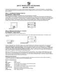


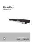

![Manuale [de]](http://vs1.manualzilla.com/store/data/006744650_1-ed92225d5e395f0fd2ab4bb1d4393f6a-150x150.png)