1
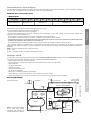
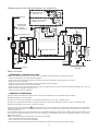
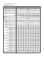
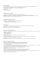
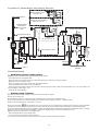
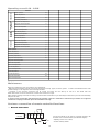
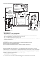
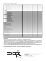
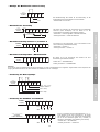
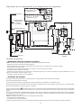
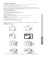
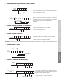
Location of thermistors and safety devices
CIRCUIT 2 similar to circuit 1
Models 500 - 600
CIRCUIT 2
CIRCUIT 2 with 1 single compressor
Models 350 - 400 - 450
ANTIFROST OPTION :
Electrical heater
Sensor in hydraulic
space
OPTIONAL: DESUPERHEATER
Water
External temperature sensor
CIRCUIT 1
Models
350 - 400 - 450 - 500 - 600
Optional: discharge T° control
Air
All year around version
actuator
Water
CIRCUIT 2
Water
Water
2 REFRIGERANT CIRCUITS
IDENTICAL
CIRCUIT 2
Commissioning
!
Verifications before commissioning
NOTE: Never start-up without having first read thoroughly the manual.
- Ensure that there are no refrigerant leak.
- Open the water circuit valves and check that water flows through the chiller when the pump operates.
- Bleed the air from the hydraulic circuit.
- Check the operation of the flow controller and chilled water interlock.
- Check that all electrical connections are firmly tightened.
- Check that the mains voltage corresponds to the unit’s voltage and that the value is within the permitted limits (+6%–10% with respect to the
nominal voltages, phase offset < 2 %).
- Check the fan rotation direction.
!
Commissioning sequence
◆ Operate the chiller outlets to provide a heat load so that the chiller can operate.
◆ Power up the main board
◆ Check that the machine is configured for local control (selection on CPU board - Parameter P103).
◆ Check that all LEDs on the control and display board operate correctly. Setting the menu 6 - Parameter P 250.
◆ Set the setpoint temperatures : chilled water - frost limit.
◆ Press the On/Off key
. A temporization from 15 to 30 second can run out before the real starting of the compressor, this temporization
corresponds to the presetting of the opening of the shutters (with all year round opération option) according to the external temperature.
◆ The unit’s internal safety devices are now enabled. If a safety device is triggered, the fault must be located, the safety device reset (for manuallyreset safety devices) and the fault acknowledged by pressing the “RESET” button. To find the fault setting the menu 7.
NOTE : to stop the unit other than in an emergency, use:
- either the ON/OFF button on the display board.
- or a dry contact on the automatic control connection.
Do not use the main switch as the electrical cabinet should remain powered (frost protection option).
28