1
UNIVERSITÉ DE LIMOGES
ÉCOLE DOCTORALE Science - Technologie - Santé
FACULTÉ des Sciences et Techniques
Laboratoire XLIM
Thèse N° 24/2006
Thèse
pour obtenir le grade de
DOCTEUR DE L’UNIVERSITÉ DE LIMOGES
Discipline : Informatique
présentée et soutenue publiquement par
Vassilios S. GOLFINOPOULOS
le 21 Juin 2006
Étude et réalisation d’un système de rétro-conception basé sur
la connaissance pour la modélisation déclarative de scènes
Thèse dirigée par Professeur Dimitri PLÉMÉNOS
Co-encadrement Professeur Georges MIAOULIS
JURY :
Président
M. le Professeur Djamchid GHAZANFARPOUR, Université de Limoges
Rapporteurs
M. le Professeur Marc DANIEL, École Supérieure d'Ingénieurs de Luminy
M. le Professeur Gérard HÉGRON, École d'Architecture de Nantes
Examinateurs
M. le Professeur Georges MIAOULIS, TEI d’Athènes
M. le Professeur Dimitri PLÉMÉNOS, Université de Limoges
Remerciements
Je tiens à témoigner ma plus profonde reconnaissance à mon directeur de recherche,
Monsieur le Professeur Dimitri PLÉMÉNOS de l’Université de Limoges, qui a dirigé ce
travail et qui m’a conseillé et encouragé avec une constante bienveillance. J’aimerais
également le remercier pour m’avoir donné la possibilité de réaliser un de mes vœux les plus
chers.
Je
remercie
Monsieur
Georges
MIAOULIS,
Professeur
d'Informatique
de
l’Etablissement d’Enseignement Technologique d’Athènes (T.E.I.), pour avoir été toutes ces
années co-encadreur et pour avoir accepté de faire partie de mon jury. Par ailleurs, je tiens à
exprimer à Monsieur Georges Miaoulis ma plus sincère gratitude pour avoir guidé mes études
et m’avoir aidé à envisager de nouvelles perspectives dans ma carrière.
De même, je remercie Monsieur le Professeur Djamchid GHAZANFARPOUR,
Directeur du Laboratoire XLIM de l’Université de Limoges, de bien vouloir présider ce jury,
et de me faire l’honneur d’être présent à la soutenance.
Monsieur le Professeur Gérard HÉGRON de l’École d'Architecture de Nantes et
Monsieur le Professeur Marc DANIEL de l’École Supérieure d'Ingénieurs de Luminy, qui ont
bien voulu être rapporteurs et participer au jury, je les prie d’accepter mes plus sincères
remerciements pour leurs précieuses remarques.
Je tiens aussi à remercier Madame Ioanna Ravani et Messieurs George Bardis, Ioannis
Dragonas, Dimitris Makris pour leur collaboration. Je remercie également Madame
Véronique Mégarioti pour sa contribution.
Enfin, j’aimerais remercier mes parents pour le soutien qu’ils m’ont apporté dans cette
longue aventure qu'ont été mes études. Ces dernières lignes sont destinées particulièrement à
ma femme qui m’a toujours soutenu malgré les difficultés et surtout mes absences auprès
d'elle. Je suis particulièrement fier de leurs dédier ce travail de recherche.
Table of
Contents
TABLE OF CONTENTS __________________________________________________________________ 1
LIST OF FIGURES ______________________________________________________________________ 5
LIST OF TABLES _______________________________________________________________________ 9
LIST OF ALGORITHMS ________________________________________________________________ 11
CHAPITRE 1
INTRODUCTION ______________________________________________________ 13
1.1 LES DOMAINES DE LA RECHERCHE ______________________________________________________ 14
1.2 LES OBJECTIFS DE LA RECHERCHE _______________________________________________________ 16
1.3 L’ORGANISATION DE LA THESE _________________________________________________________ 18
CHAPTER 2
RELATED RESEARCH AREAS ____________________________________________ 21
2.1 GEOMETRIC MODELLING ______________________________________________________________ 21
2.2 DECLARATIVE MODELLING ____________________________________________________________ 24
2.2.1 General and dedicated declarative modellers _________________________________________ 30
2.2.2 The declarative conception cycle ___________________________________________________ 30
2.2.3 The iterative design process _______________________________________________________ 32
2.2.4 Levels of abstraction and levels of detail _____________________________________________ 33
2.2.5 Declarative modelling by hierarchical decomposition___________________________________ 34
2.2.6 MultiCAD system architecture _____________________________________________________ 37
2.3 FEATURE-BASED MODELLING __________________________________________________________ 40
2.4 REVERSE ENGINEERING _______________________________________________________________ 43
2.4.1 Reverse engineering in scene modelling______________________________________________ 44
2.4.2 Reverse engineering and geometric modelling_________________________________________ 47
2.4.3 Reverse engineering and feature-based modelling______________________________________ 49
2.4.4 Reverse engineering and declarative modelling________________________________________ 52
2.5 DISCUSSION________________________________________________________________________ 54
2
Table of Contents
CHAPTER 3
THESIS PROPOSAL AND IMPLEMENTATION _____________________________ 57
3.1 INTEGRATION OF THE TWO MODELS _____________________________________________________ 58
3.2 RECONSTRUCTION PHASE _____________________________________________________________ 60
3.3 EXTENDED DESIGN METHODOLOGY______________________________________________________ 61
3.4 RS-MULTICAD SYSTEM ARCHITECTURE _________________________________________________ 62
3.4.1 Data and knowledge storage ______________________________________________________ 65
3.4.2 The stratified representation_______________________________________________________ 70
3.4.3 Scene modifications _____________________________________________________________ 72
3.4.4 The propagation policy___________________________________________________________ 74
3.4.5 The resultant declarative description ________________________________________________ 75
3.5 RS-MULTICAD PROTOTYPE ___________________________________________________________ 76
3.5.1 Geometric representation _________________________________________________________ 76
3.5.2 The construction of the stratified representation _______________________________________ 79
3.5.3 Extraction of relations and properties _______________________________________________ 82
3.5.4 The propagation policy___________________________________________________________ 85
3.5.5 Scene modifications _____________________________________________________________ 86
3.5.5.1 Move operation _______________________________________________________________________ 86
3.5.5.2 Scale-resize operation __________________________________________________________________ 88
3.5.5.3 Insert operation _______________________________________________________________________ 90
3.5.5.4 Deletion operation _____________________________________________________________________ 91
3.5.5.5 Extra geometric characteristics operation ___________________________________________________ 91
3.5.6 The resultant declarative description ________________________________________________ 91
CHAPTER 4
EXPERIMENTAL RESULTS ______________________________________________ 95
4.1 RS-MULTICAD ENVIRONMENT ________________________________________________________ 95
4.1.1 Select mode____________________________________________________________________ 98
4.2 CASE I – INTERNAL MULTICAD GEOMETRIC MODEL ________________________________________ 98
4.2.1 Scene modifications ____________________________________________________________ 100
4.2.1.1 Object rename _______________________________________________________________________ 100
4.2.1.2 Move ______________________________________________________________________________ 100
4.2.1.3 Scale-Resize ________________________________________________________________________ 105
4.2.1.4 Insert ______________________________________________________________________________ 110
4.2.1.5 Delete______________________________________________________________________________ 112
4.2.1.6 Change extra geometric characteristics____________________________________________________ 113
4.2.1.7 Change the rule set ___________________________________________________________________ 113
4.2.2 Model storage_________________________________________________________________ 116
4.2.2.1 Save the declarative description _________________________________________________________ 116
4.2.2.2 Save the geometric solution ____________________________________________________________ 117
Table of Contents
3
4.2.3 Reduction of the solution space ___________________________________________________ 117
4.2.3.1 Automated way ______________________________________________________________________ 118
4.2.3.2 Manual way _________________________________________________________________________ 120
4.3 CASE II – EXTERNAL GEOMETRIC MODEL ________________________________________________ 122
4.3.1 Scene modifications ____________________________________________________________ 123
4.3.1.1 Import geometric model _______________________________________________________________ 123
4.3.1.2 Object rename and type selection ________________________________________________________ 124
4.3.1.3 Insert ______________________________________________________________________________ 125
4.3.1.4 Change the geometric characteristics _____________________________________________________ 126
4.3.1.5 Delete______________________________________________________________________________ 126
4.3.1.6 Change the rule set ___________________________________________________________________ 127
4.3.1.7 Move ______________________________________________________________________________ 129
4.3.1.8 Scale-Resize ________________________________________________________________________ 131
4.3.2 Model storage_________________________________________________________________ 134
4.3.2.1 Save the declarative description _________________________________________________________ 134
4.3.2.2 Save the geometric solution ____________________________________________________________ 135
4.3.3 Reduction of the solution space ___________________________________________________ 136
4.3.3.1 Automated way ______________________________________________________________________ 136
4.3.3.2 Manual way _________________________________________________________________________ 137
4.4 DISCUSSION_______________________________________________________________________ 140
CHAPITRE 5
CONCLUSIONS ET PERSPECTIVES____________________________________ 143
5.1 REMARQUES DE CONCLUSION _________________________________________________________ 146
5.2 PERSPECTIVES DE RECHERCHE ________________________________________________________ 149
BIBLIOGRAPHY ______________________________________________________________________ 151
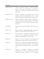
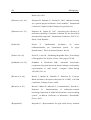
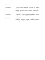
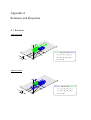
APPENDIX A
RELATIONS AND PROPERTIES _______________________________________ 163
A.1 RELATIONS _______________________________________________________________________ 163
A.2 PROPERTIES ______________________________________________________________________ 169
APPENDIX B
DXF FORMAT _______________________________________________________ 171
APPENDIX C
THE TRADITIONAL GEOMETRIC MODELLER _________________________ 175
List of
Figures
Figure 2.1 Example of polyhedron generated by PolyFormes __________________
27
Figure 2.2 Example of box arrangement and form growth by VoluFormes ________ 28
Figure 2.3 Scenes created by Dem2ons ____________________________________
29
Figure 2.4 Examples of generated buildings by BatiMan ______________________ 29
Figure 2.5 The declarative conception cycle ________________________________ 31
Figure 2.6 The iterative design process ____________________________________ 32
Figure 2.7 Evolution of the design process _________________________________ 33
Figure 2.8 A typical example of a decomposition tree ________________________
36
Figure 2.9 Solutions of MultiFormes _____________________________________
36
Figure 2.10 The working space of MultiCAD ______________________________
39
Figure 2.11 A boundary model __________________________________________
42
Figure 2.12 The transformation of models _________________________________
45
Figure 2.13 Models according to the level of abstraction ______________________
47
Figure 3.1 Type of acquired knowledge according to level of abstraction _________
58
Figure 3.2 The transformation of a geometric model into declarative ____________
59
Figure 3.3 The new declarative conception cycle ____________________________ 60
Figure 3.4 Extended design methodology and modelling levels ________________
61
Figure 3.5 General architecture of RS-MultiCAD system _____________________
62
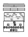
Figure 3.6 Detailed system architecture of RS-MultiCAD system _______________ 64
6
List of Figures
Figure 3.7 The inner operation cycle of RS-MultiCAD _______________________
65
Figure 3.8 The ER diagram of data and knowledge storage ____________________
66
Figure 3.9 The basic structure ___________________________________________ 70
Figure 3.10 A typical stratified representation ______________________________ 71
Figure 3.11 The propagation policy ______________________________________
74
Figure 3.12 The generalization factor _____________________________________
75
Figure 3.13 The roof morphology ________________________________________ 77
Figure 3.14 Control points of B-Spline curves ______________________________
78
Figure 3.15 A typical linked list of the declarative layer ______________________
79
Figure 3.16 A tree of two decomposition levels _____________________________
80
Figure 3.17 The decomposition tree ______________________________________
81
Figure 3.18 The calculation of spatial relations _____________________________
84
Figure 3.19 The IDEF3 diagram of the propagation policy ____________________
86
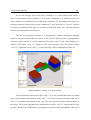
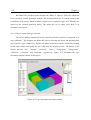
Figure 4.1 The working space of RS-MultiCAD ____________________________
96
Figure 4.2 The stratified representation of Case I ____________________________ 99
Figure 4.3 Move “long_building” to new position ___________________________
100
Figure 4.4 Move “kitchen_8” to new position ______________________________
100
Figure 4.5 Move “flat_7” to new position _________________________________
102
Figure 4.6 Violation of “kitchen_8” move _________________________________
103
Figure 4.7 Move “kitchen_8” to new position ignoring the rule set ______________
103
Figure 4.8 Position not available _________________________________________ 104
Figure 4.9 Move “long_building” ________________________________________
105
Figure 4.10 Resize “bathroom_9” ________________________________________ 106
List of Figures
7
Figure 4.11 Resize “flat_7” to a new length ________________________________
106
Figure 4.12 Violation of resize “flat_7” ___________________________________
107
Figure 4.13 Resize “storage_12” to a new height ____________________________
107
Figure 4.14 Position not available ________________________________________ 108
Figure 4.15 Scale “aux_building” ________________________________________
109
Figure 4.16 Position not available ________________________________________ 109
Figure 4.17 Object insertion ____________________________________________
110
Figure 4.18 Further objects insertion _____________________________________
111
Figure 4.19 Insert an abstract object ______________________________________
111
Figure 4.20 The result of the insertion ____________________________________
112
Figure 4.21 Delete an object ____________________________________________
112
Figure 4.22 Change extra geometric characteristics __________________________
113
Figure 4.23 Rule set enhancement _______________________________________
115
Figure 4.24 Save the declarative description _______________________________
116
Figure 4.25 Save the geometric solution ___________________________________ 117
Figure 4.26 Reduce the solution space ____________________________________
118
Figure 4.27 Experimental results of automated reduction of the solution space ____
119
Figure 4.28 Geometric solutions generated by the automated way ______________
120
Figure 4.29 Experimental results of manual reduction of the solution space _______
121
Figure 4.30 Geometric solutions generated by the manual way _________________
122
Figure 4.31 An external geometric model __________________________________ 123
Figure 4.32 Import of an external geometric model __________________________
123
Figure 4.33 Type declaration and object rename ____________________________
124
8
List of Figures
Figure 4.34 Insert an abstract object of type “house” _________________________
125
Figure 4.35 Insert an object of type “roof” _________________________________
125
Figure 4.36 Change extra geometric characteristics __________________________
126
Figure 4.37 The deletion of the object “roof_11”____________________________
127
Figure 4.38 Spatial relations ____________________________________________
128
Figure 4.39 Move object “kitchen” _______________________________________ 129
Figure 4.40 Move the object “office” ignoring the rule set ____________________
130
Figure 4.41 Position not available ________________________________________ 130
Figure 4.42 Resize “kitchen” to a new length _______________________________ 131
Figure 4.43 Resize “kitchen” to a new width _______________________________
132
Figure 4.44 Position not available ________________________________________ 132
Figure 4.45 Resize “vcorridor” to a new length _____________________________
133
Figure 4.46 Violation of scaling the “house_10” ____________________________
134
Figure 4.47 Save the declarative description _______________________________
134
Figure 4.48 Save the geometric solution ___________________________________ 135
Figure 4.49 Geometric solutions generated by the automated way ______________
137
Figure 4.50 Experimental results of automated reduction of the solution space ____
137
Figure 4.51 Geometric solutions generated by the manual way _________________
139
Figure 4.52 Experimental results of manual reduction of the solution space _______
139
Figure B.1 The DXF file of a 3D box _____________________________________
173
Figure C.1 The object model of VectorDraw _______________________________
177
List of
Tables
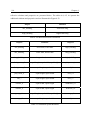
Table 3.1 The spatial relations __________________________________________
67
Table 3.2 The declarative properties ______________________________________ 68
Table 3.3 The reflective relations ________________________________________
69
Table 3.4 The pure geometric properties __________________________________
69
Table 4.1 Spatial Relations – Case I ______________________________________
98
Table 4.2 Reflective Relations – Case I ___________________________________
99
Table 4.3 Properties – Case I ___________________________________________
100
Table 4.4 Additional Reflective Relations – Case I __________________________
114
Table 4.5 Additional Spatial Relations – Case I _____________________________
114
Table 4.6 Additional Properties – Case I __________________________________
115
Table 4.7 Automated reduction of the solution space – Case I __________________ 119
Table 4.8 Manual reduction of the solution space – Case I ____________________
121
Table 4.9 Properties – Case II ___________________________________________
127
Table 4.10 Automated reduction of the solution space – Case II ________________
136
Table 4.11 Manual reduction of the solution space – Case II ___________________
138
Table B.1 Group code value types _______________________________________
172
Table B.2 Group codes ________________________________________________
172
List of
Algorithms
Algorithm 3.1 Convert a linked list into a decomposition tree __________________
82
Algorithm 3.2 Extract relations and properties ______________________________
83
Algorithm 3.3 Compute the spatial relations _______________________________
84
Algorithm 3.4 Move operation __________________________________________
87
Algorithm 3.5 Scale and resize operation __________________________________
89
Algorithm 3.6 Insert operation __________________________________________
90
Algorithm 3.7 Set the generalization factor ________________________________
92
Chapitre 1
Introduction
Lors des dernières décennies, la modélisation géométrique est devenue un outil
précieux pour diverses applications dans de nombreux domaines tels que la conception
industrielle et architecturale, la fabrication ainsi que l’ingénierie électrique et mécanique. La
conception et la fabrication d’objets, aussi diverses que des bâtiments, des voitures, des
bateaux etc., exploitent les avantages de la technologie naissante. En conséquence, les objets
physiques ont été largement remplacés par des modèles géométriques puisque les systèmes
assistés par ordinateurs imposent cette tendance et facilitent l’applicabilité dans cette
direction. Ceci offre des produits meilleur marché et de meilleure qualité car ils sont plus
simples à analyser et plus faciles à changer que les précédents.
Le processus de conception est fréquemment considéré en termes de plusieurs phases
séquentielles [Pahl 96]: conception conceptuelle, conception préliminaire ou d’ensemble et
conception détaillée.
Pendant la conception conceptuelle, la fonctionnalité désirée d’un
produit est déterminée, les solutions de conception potentielles et leurs performances
correspondantes sont développées.
En outre, les dépenses prévues sont estimées, les
restrictions aux solutions potentielles sont imposées et une spécification générale du produit,
consistant en une description des concepts de conception avec des contraintes de fonction et
de comportement, est définie. Le fondement essentiel de la conception conceptuelle est de
réaliser les objectifs, la fonctionnalité et les propriétés satisfaisant les objectifs d’un nouveau
modèle. Dans la conception d’ensemble, le foyer passe de la synthèse du modèle conceptuel
à l'exploration des solutions de conception potentielles. Un ensemble de configurations
réalisables du modèle est défini suite à l'examen des diverses combinaisons des composants
de modèles, leurs contraintes et interactions, ainsi que les ressources et les technologies
disponibles pour garantir que tous les composants peuvent être principalement manufacturés.
L’objectif de la conception détaillée est de développer l'efficacité la plus élevée possible de
tous les composants modèles, afin de produire des schémas nécessaires, des détails
techniques, des caractéristiques et des tolérances qui permettront au modèle d'être fabriqué.
14
Chapitre 1
Le processus de conception architectural [Simon 96] se concentre sur la définition
détaillée d’un modèle spatial de manière à permettre sa réalisation matérielle. Pour tout
produit ou système architectural, le processus de conception débute par la conception
conceptuelle dont le but est de produire un modèle ou la représentation d'une entité qui sera
plus tard construite. Le processus traite de la combinaison de l'intuition et du jugement basés
sur l’expérience acquise par la construction de modèles semblables. De plus, le processus
traite d’un ensemble de principes dans le cadre duquel le modèle évolue, d’un ensemble de
critères qui permet à la qualité d'être jugée et d’un processus d’itération qui mène à une
représentation de conception finale.
1.1 Les domaines de la recherche
La modélisation déclarative [Lucas et al., 90] est une méthode de modélisation
alternative qui adapte le processus de conception, surmonte les inconvénients de la
modélisation géométrique et permet au concepteur de décrire la scène désirée en définissant
ses propriétés, qui peuvent être précises ou imprécises, et ce sans indiquer la façon d’obtenir
une scène avec ces propriétés.
La modélisation déclarative libère le concepteur de
l’obligation de définir les propriétés géométriques des entités et facilite la description de scène
en requérant uniquement quelques propriétés déjà connues. La modélisation déclarative traite
de la description vague des objets et offre au concepteur un environnement pratique pour
l'expression précise de l'idée de conception conçue [Plemenos et al., 02].
Une approche
spéciale de la modélisation déclarative est la modélisation déclarative par décomposition
hiérarchique [Plemenos 91], [Plemenos 95]. Cette approche fournit au concepteur la capacité
de décrire la scène désirée en décomposant la scène de manière descendante (de haut en bas) à
des niveaux de détails différents et facilite la description de scènes complexes. Au contraire,
les systèmes de conception conventionnels assistés par ordinateur encouragent le concepteur à
employer une approche de conception ascendante (de bas en haut).
La modélisation déclarative de scènes est basée sur le cycle de conception déclaratif,
qui consiste en trois phases séquentielles. La première est la description de scène déclarative
où le concepteur décrit comment elle/il perçoit la scène désirée en définissant des propriétés
de la scène ou sans les définir. La seconde est la phase de génération où le mécanisme
générateur de solutions produit un ensemble de solutions géométriques alternatives qui
Introduction
15
vérifient les propriétés définies [Lucas et al., 90], [Lucas et al., 95]. Finalement, la troisième
est la phase de compréhension de solution où les solutions géométriques sont visualisées par
un modeleur géométrique [Lucas et al., 95], [Plemenos 95].
La modélisation déclarative permet le processus de conception itératif par l’exécution
du cycle de conception déclaratif et ensuite, facilite le concepteur dans sa réévaluation de la
description initiale de scène [Desmontils 95]. Le but fondamental des cycles d'exécution
successifs est que le système doit converger vers un ensemble de solutions géométriques
alternatives qui sont plus fidèles aux exigences du concepteur. Le processus itératif se
termine lorsque le concepteur estime qu’elle/il a atteint le but escompté.
L'architecture MultiCAD [Miaoulis et al., 96], [Miaoulis et al., 98] est une architecture
des systèmes d’information multimédia et intelligents pour la Conception Assistée par
Ordinateur (CAO) libérées de l'inflexibilité géométrique qui met en application la
modélisation déclarative en acceptant une description de scène et en produisant un ensemble
de solutions géométriques alternatives qui satisfont la description de scène elle-même. Parmi
d'autres bases de données, MultiCAD incorpore une base de données de connaissance qui
contient la connaissance spécifique du domaine, en d’autres termes toutes les informations
nécessaires sur le type d'objets, le type de relations et le type de propriétés d'un domaine
spécifique. Le concepteur exploite la base de connaissance pendant la phase de description de
scène afin de définir les objets, les relations et les propriétés appropriés selon la connaissance
de domaine spécifique.
La rétro-conception transforme, dans le concept de modélisation, un modèle de niveau
d'abstraction spécifique en modèle d'un niveau d'abstraction plus élevé; ce qui constitue une
étape largement reconnue comme étape cruciale dans le cycle de conception du produit. La
rétro-conception s'oppose à l’ingénierie directe qui est un processus produisant les pièces
physiques à partir du modèle géométrique. Beaucoup de techniques ont été développées et
décrites dans une vaste littérature sur la rétro-conception. La méthodologie de la rétroconception a été combinée avec de nombreuses méthodes de modélisation telles la
modélisation géométrique et la modélisation par les caractéristiques. La reconstruction en
trois dimensions (3D) est une des branches principales de la rétro-conception où un objet
physique est transformé en modèle géométrique de diverses représentations [Varady 97].
16
Chapitre 1
La rétro-conception incorpore un processus de bas niveau pour la reconstruction du
modèle géométrique en 3D et un processus de haut niveau basé sur la connaissance pour la
compréhension sémantique de la scène. L’approche basée sur la connaissance dépasse les
méthodes d'extraction par des caractéristiques puisqu’elle est employée pour extraire des
rapports et des propriétés à partir d'un modèle géométrique donné et pour saisir l'information
géométrique et non-géométrique dans le même schéma de représentation intelligente.
Le processus de conception déclarative produit un ensemble de modèles géométriques
alternatifs qui sont basés sur un modèle déclaratif et abstrait.
Dans la méthode de
modélisation déclarative, la rétro-conception pourrait jouer un rôle significatif et sera adaptée
afin de transformer un modèle géométrique en modèle plus abstrait, le modèle déclaratif.
La motivation de cette recherche doit combiner la méthode de modélisation
déclarative, telle qu’elle est appliquée dans l'architecture MultiCAD, avec la méthodologie de
rétro-conception afin de fournir une compréhension sémantique des modèles géométriques,
qui sont produits à partir de l'architecture du système MultiCAD. Le processus de rétroconception de haut niveau est une approche sémantique qui saisit l'information géométrique et
non-géométrique, toutes deux extraites de la représentation géométrique en appliquant la
connaissance de domaine spécifique, dans la même représentation intelligente. La base de
connaissance du système MultiCAD incorpore la connaissance spécifique de domaine relative
au type d’objets, de rapports et de propriétés. La connaissance fait référence à la conception
architecturale des bâtiments.
1.2 Les objectifs de la recherche
Le but principal de la thèse est de transformer un modèle géométrique en modèle
déclaratif dans le cadre de la modélisation déclarative pendant la première partie du processus
de conception.
Afin d’atteindre ce but, une approche de rétro-conception basée sur la
connaissance a été développée dans le but de réaliser le couplage d’un modeleur géométrique
classique à un modeleur déclaratif. L'approche est placée dans le cadre de la modélisation
déclarative et de la rétro-conception.
Introduction
17
L'approche de rétro-conception basée sur la connaissance implique le développement
d'un système intelligent de prototype, qui fonctionne dans l'architecture MultiCAD, pour la
conception architecturale des bâtiments.
MultiCAD reçoit une description déclarative des conditions de bâtiment et produit un
ensemble de modèles géométriques alternatifs. Le concepteur choisit une représentation
géométrique désirée.
Le système intelligent de prototype comprend sémantiquement la
représentation géométrique sélectionnée et permet au concepteur d'effectuer des modifications
géométriques et topologiques sur la scène spécifique. Le système vérifie si les modifications
sont conformes ou non aux conditions initiales du bâtiment. Le système aboutit sur un
modèle déclaratif, qui incarne les modifications du concepteur. Cette nouvelle description
déclarative est fournie à la phase déclarative de description MultiCAD et, une nouvelle
itération débute.
Une démonstration d'une série de résultats expérimentaux fournit la
certitude qu'un tel système est réalisable et efficace.
Afin d'accomplir le but principal les objectifs suivants doivent être pris en
considération:
•
Surmonter les problèmes de l'intégration du modeleur géométrique et déclaratif dans le
cycle conceptuel déclaratif. Une description de scène déclarative produit un ensemble de
modèles géométriques alternatifs qui répondent aux exigences du concepteur. D'autre
part, un modèle géométrique peut correspondre à plus d'une description de scène
déclarative. Ceci se produit parce que le modèle géométrique spécifique appartient à
l'intersection de plusieurs ensembles de modèles géométriques (espaces de solutions) qui
ont été produits à partir de modèles déclaratifs différents. Par conséquent, les différentes
descriptions de scène déclaratives peuvent mener à la même représentation géométrique
et aussi, une représentation géométrique spécifique pourrait mener à plusieurs
descriptions de scène déclaratives.
•
Surmonter les problèmes de saisie d'information géométrique et non-géométrique. Les
représentations classiques sont incapables de saisir et de manipuler l'information
géométrique et non-géométrique sous la même forme, leurs natures étant différentes.
L'intelligence artificielle et les approches orientées-objet fournissent une représentation
18
Chapitre 1
spécialisée afin de saisir et gérer correctement l'information géométrique et nongéométrique sous la même représentation.
•
Surmonter les problèmes relatifs aux modifications effectuées par le concepteur sur la
scène. Dès que le concepteur a choisi un modèle géométrique désiré, elle/il a la capacité
d'effectuer les modifications qui changent la géométrie des objets qui constituent la scène
et/ou qui affectent la topologie de la scène.
Toutes les modifications doivent être
vérifiées en fonctions des exigences initiales du concepteur et doivent être également
prises en considération pour le modèle déclaratif résultant.
•
Surmonter les problèmes d'importation des modèles géométriques construits par un autre
modeleur géométrique classique. MultiCAD produit les modèles géométriques qui bien
qu’ils contiennent l'information géométrique, ils contiennent également le type d'objets
qui constituent la scène.
supporte
L'approche basée sur la connaissance de rétro-conception
également l'importation des modèles géométriques construits par un autre
modeleur géométrique classique en fournissant les équipements nécessaires pour
recueillir toute l'information appropriée au concepteur. De cette façon, le concepteur a la
capacité de continuer les manipulations, de modifier la scène et d'inclure la scène dans le
cycle conceptuel déclaratif.
1.3 L’organisation de la thèse
Le chapitre 2 illustre les domaines de recherches principaux de cette thèse: le cadre de
modélisation déclarative, le cycle de conception déclaratif ainsi que le processus itératif de
conception de la modélisation déclarative sont présentés. Une brève vue d'ensemble des
représentations géométriques de base est présentée avec les avantages et les inconvénients de
la modélisation géométrique. En outre, on présente la méthode de rétro-conception qui
permet la transformation d'un modèle en un modèle de niveau d'abstraction plus élevé. Le
chapitre propose une brève révision de la reconstruction 3D qui présente le processus de bas
niveau du rétro-conception en modélisation. En outre, la rétro-conception dans la
modélisation par les caractéristiques est esquissée afin d'accentuer le champ d'identification
du dispositif. La dernière sous-section présente que la rétro-conception dans l'approche de la
Introduction
19
modélisation déclarative qui est employée pour transformer un modèle géométrique choisi en
un modèle de niveau d'abstraction plus élevé, le modèle déclaratif.
Le chapitre 3 illustre la proposition et la réalisation de la thèse. L'intégration des deux
modèles, déclaratif et géométrique, a lieu par l’introduction d’une nouvelle phase, la phase de
reconstruction dans le cycle de conception déclaratif. L'architecture du système proposé et la
représentation dynamique de la mémoire sont présentées.
Par ailleurs, une série de
modifications de scène est définie et une politique de propagation, suivie par le système
proposé afin d'absorber ou de ne pas absorber des modifications de scène, est esquissée. La
politique de propagation est utilisée, après une modification de scène, afin que le système
mette correctement à jour la représentation intelligente. La sous-section suivante décrit la
construction de la description déclarative résultante qui sera transmise à la phase de
description déclarative dans l’itération MultiCAD suivante. De plus, la sous-section suivante
est consacrée à la mise en oeuvre et présente les algorithmes principaux que le prototype
proposé incorpore. De tels algorithmes concernent la construction de la représentation de la
mémoire dynamique, la manipulation des modifications de scène ainsi que la construction de
la description déclarative résultante.
En conclusion, la dernière sous-section illustre les
conditions du réalisateur pour le choix du modeleur géométrique classique d'une part et,
d'autre part, présente les caractéristiques principales du modeleur géométrique classique
choisi.
Le chapitre 4 présente les résultats expérimentaux qui sortent de la fonctionnalité
soulignée du système proposé. La première sous-section présente un bref mode d’emploi de
l'environnement de travail proposé et dans la deuxième et la troisième sous section illustrent
des cas différents.
Enfin, le chapitre 5 présente les remarques de conclusion et les nouvelles directions
pour la future recherche.
Chapter 2
Related Research Areas
The objective of this chapter is to illustrate the main research areas of this thesis.
Declarative modelling transforms an abstract model into a set of geometric representations so
a brief overview of the basic geometric representations is presented along with the advantages
and the disadvantages of geometric modelling.
Besides, the state of the art of declarative modelling is presented, describing the
general and dedicated declarative modellers, the declarative conception cycle, and the
iterative design process of declarative modelling.
Afterwards, the levels of abstraction and the levels of detail of declarative modelling
are discussed. A special attention is given on the MultiFormes system and a detail
presentation of the MultiCAD system is illustrated since it will be the system framework
under which the proposed system of this thesis will develop.
Finally, the reverse engineering paradigm is presented which permits the
transformation of one model into another one. In the framework of geometric modelling,
reverse engineering is used in order to construct a 3D model from a physical model. Even if it
is out of scope of this thesis, a brief presentation is given. Furthermore, the reverse
engineering in feature-based modelling is sketched in order to highlight the field of feature
recognition. Finally, in the declarative modelling approach, reverse engineering is used to
transform geometric model, which corresponds to a geometric solution, into a more abstract
model, the declarative model.
2.1 Geometric modelling
Geometric modellers are powerful design tools with which complex shapes can be
modelled, edited, manipulated and graphically verified. There are three types of geometric
representations, i.e. wire-frame, surface and solid models [Mortenson 85]. Wire-frame models
only contain vertex and edge information about objects and are therefore unsuited to
22
Chapter 2
reasoning about the transformation of solid objects. However, lack of explicit surface
information can lead to models which are ambiguous, incomplete or even impossible to
manufacture as they can correspond to no physical 3D object [Goldman 87]. These drawbacks
led to the search of more sophisticated schemes and gave way to surface and solid modellers.
Similarly, surface models suffer from only containing face information while solid models are
capable of a complete and unambiguous geometric description of objects.
Surfaces are used explicitly to describe an object in surface modellers. More complex
shapes can be modelled with surface modelling than with wire-frames. By definition, a solid
is a 3D object with a well defined inside and outside separated by a two-dimensional (2D)
boundary. Many techniques have been developed for generating and storing geometric models
which are represented as solids, such as Constructive Solid Geometry (CSG), Boundary
representation (B-rep), octrees and others [Requicha 80]. CSG models use geometric
primitives which are attractive for the creation of feature primitives, but do not contain
sufficient structured or detailed information about the faces, edges and vertices of
components. This kind of information, which is essential for reasoning about the geometry
and for tolerance definition, is explicitly represented in B-rep models.
From the point of view of the techniques used for geometric modelling purposes, there
are two basic approaches: transfinite interpolation and discrete approximation and
interpolation. In transfinite interpolation, a surface is constructed such that it goes through a
given collection of curves. Cross-sectional design is an example of a method that falls into
this category [Woodward 87]. In discrete approximation-interpolation, a surface that
approximates/interpolates a given set of data points is constructed.
Based on the manner in which a change in the data affects the curve or surface to be
constructed, we can categorise methods into global and local. In global methods, a change in
the data affects the whole surface while in local methods such a change affects the surface
locally. In the first category there are methods like the Gordon surface [Gordon 69] and
polynomial Bézier surfaces. However, if there are a lot of data the degree of the polynomial
surface required to fit the data is high, which makes the resulting surface unreasonably
complicated for further manipulations. Therefore, designers are more interested in local
methods in which a change in the data affects the curve or surface locally. Local methods
Related Research Areas
23
invoke piecewise triangular polynomials or bipolynomials to define the desired surface. Such
techniques include piecewise Bézier, B-Splines, Rational B-Splines and NURBS curves and
surfaces.
Usually, there is an initial polygonal or polyhedral approximation of the desired object
given in terms of a triangulation [Schumaker 93] or a rectangular grid of control points. The
initial polygon or polyhedron is then smoothed using triangular or rectangular piecewise
smooth patches. For piecewise Bézier, one has to enforce smoothness conditions between
adjacent patches [Gregory 89], [De Rose 90], but with the B-Spline or NURBS scheme, this
comes without any special tricks.
A drawback of rectangular patches is their limited ability to model complex
topologies. Very often there are n-sided holes within a rectangular patch complex. Techniques
for filling such holes with smooth triangular or rectangular patches have been reported earlier
[Farin 82]. However, such problems are avoided using triangular patches, as more complex
topologies can be modelled with triangles rather than with rectangles. However, triangular or
rectangular patches are not the only ones available for modelling purposes. There have also
been n-sided patches and smoothing techniques based on them reported in the literature
[Charrot et al, 84], [Várady 91].
The current CAD applications are based on parametric tools and need all relevant
information to create the desired object which means that do not offer any assistance at the
conception itself, since the designer should know all the details of the object to be created
before calling upon the CAD system. A CAD system in order to overleap this disadvantage
should deal with the lack of information on the non-geometrical aspects of the object, the lack
of levels of abstraction, and the possibility to input imprecise description.
Geometric models are collections of components with well-defined geometry and
often, interconnections between components [Foley at al., 99]. One of the problems is to give
an accurate geometrical representation to an object. Primitives must be used for modelling an
object. The primitives are often selected dependent on the specific object and the level of
accuracy required.
24
Chapter 2
Practically, traditional geometric modelling is generally applied to well defined,
simple objects and objects without well defined geometry by their nature cannot be
represented and even more, a complex object may require hard work to be represented.
Furthermore, geometric modelling suffers from poverty on scene construction which obliges
the designer to know with precision all objects that constitute the scene in advance.
A classic geometric model cannot hold information on the non-geometric aspects of
the objects. This may include physical properties, such as colour, density, cost and other
properties. A geometric model misses a level of abstraction, which means that the model
represents a specific object and not all or few similar objects. The geometric model is defined
in terms of a precise geometry.
The designer has to convert his/her mental idea into specifications in an imperative
way in terms of co-ordinates and dimensions of the various objects. When the number of
different objects is large that turns to be impossible task. The designer must be able to
describe an image in a more abstract way by stating the relations and the properties of the
objects without worrying about the geometry of the objects.
2.2 Declarative modelling
Declarative modelling is an approach [Lucas et al., 90] that can deal with the
insufficiency of CAD applications. Declarative modelling allows the designer to use
imprecise information in a scene description. The declarative modelling paradigm introduces
property based modelling techniques by providing the possibility of scene description using
properties, which can be either precise or imprecise [Plemenos 91], [Plemenos 95], [Lucas et
al., 90] and differentiates from traditional geometric modelling since does not require
precision modelling tools. Declarative modelling is a total approach of the designing process
[Plemenos et al., 02]. Declarative modelling permits the designer to describe a desirable scene
by only giving some expected properties of the scene and letting the declarative modeller find
alternative solutions, if any, verifying these properties.
The designer can describe a scene intuitively in declarative modelling. An abstract description
and a vague description of the properties of the desired scene are acceptable by the declarative
modelling. When the designer describes a scene intuitively in terms of common expressions,
Related Research Areas
25
the described properties are in many cases imprecise. The imprecision of a described property
is presented when many values can satisfy that property on one hand, while on the other hand
is presented due to the fuzziness of a property [Plemenos et al., 02]. Both cases lead
declarative modelling to be characterised as a time consuming modelling approach.
The designer has to supply a description of the desired scene from the designer along
with the relations of the different parts of the scene. The designer does not concern about
checking the properties of the desired scene this is done by the modeller. The solution adopted
at the end of the process will thus check the whole of the criteria of description.
A declarative modeller can also handle other information than purely geometric. The
designer can describe a desirable scene on high level of abstraction. For example, the weight
of an object design can be a criterion taken into account for a relation between several objects
in the design process.
Declarative modelling is adapted to the integral management of the design process.
The same object can be perceived differently according to the domain, which means that the
same object looks like differently and its usefulness varies in several domains. Besides,
another designer could describe in another way the same object by using different properties.
Declarative modelling can deal with the whole of the process of design since various
properties are checked on the design process.
On the other hand, the interpretation of description is a significant problem of the
declarative modelling since the handling of high-level concepts often leads to various
interpretations.
The majority of declarative modellers use the exploration of a universe to seek the
scenes that meet the properties of description. This search can lead the designer to solutions,
which he did not consider. However, the presentation of all the possible solutions can be a
deliberated choice of certain modellers, regardless the number of the solutions. Thus, the
designer should manage different solutions that appear similar.
Declarative modelling has preoccupied the scientific community during the last fifteen
years. Kochhar of MIT worked on declarative modelling in [Kochhar 90] and [Kochhar 94].
26
Chapter 2
Kochhar accentuates the exploratory aspects of geometric modelling where the modelling is
broken up into two sub-tasks, the design and the articulation. The design comprises the
creative aspects of modelling and the articulation comprises the specification of the geometry
and the physical properties.
Kochhar introduces the Cooperative Computer Aided Design in [Kochhar 90] and
[Kochhar 94] in order to facilitate the integration of generative and traditional modelling
systems by allowing the designer to guide the generative system through successive rounds of
automated geometric modelling. The notion of generative modelling is very close to the
notion of declarative modelling, as in both cases imprecise descriptions can generate many
solutions. An experimental cooperative scene modeller was implemented for a generative
system based on the formal language of schema grammars.
The Cooperative Computer Aided Design framework is based on the fact that a
generative geometric modelling (GGM) system exists and generates a set of designs based on
some designer-defined constraints or properties, the GGM system is supposed that does not
produce perfect designs so it must guided to search for better designs by the human designer
and finally the GGM system produces a large set of designs, a specialised browsing system
allows the designer to search the set of generated designs in a directed manner.
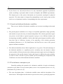
A typical modelling session using the CCAD system proceeds as follows:
• The designer uses the traditional geometric modelling (TGM) system to generate a nascent
design to be used in the first iteration of automated modelling.
• The designer then uses a dialog with the GGM system to define the constraints to be used
during the generation process.
• The GGM system then instantiates all valid geometric designs. These designs are presented
as icon-like buttons in a large screen area and the designer can get a large image of a
design by clicking on the corresponding button.
• The designer then selects a set of promising designs using the browsing system.
Related Research Areas
27
• The selected designs are then returned to GGM system and the last four steps are repeated
until the desired design has been constructed.
Many declarative modellers have been germinated in France most of them are limited
to very restricted domains:
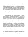
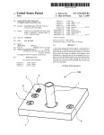
• PolyFormes. In [Martin P. and D., 88], [Martin P. and D., 89] PolyFormes is a specialised
declarative modeller which is based on regular and semi-regular polyhedra that can be
very complex. The goal of PolyFormes is to generate all regular and semi-regular
polyhedra according to user’s requests which are expressed through dialog boxes. The use
description is translated into an internal model which is expressed in terms of rules and
facts. PolyFormes in order to generate solutions uses an inference engine which applies
rules to the facts and creates new facts and explores the solution space. Figure 2.1 presents
an example of polyhedron generated by PolyFormes.
Figure 2.1 Example of polyhedron generated by PolyFormes
• PastoFormes. In [Colin 88], [Colin 90] PastoFormes is a declarative modeller based on
elementary polyhedrons. Objects are modelled by joining elementary polyhedrons.
• UrbaFormes. In [Le Goff 90] is presented a declarative modeller for urban morphology.
This modeller proposes to establish in a declaratory way a route and allows discovering
urban aspects of a given city.
• MultiFormes. In [Plemenos 91] is presented a declarative modeller based on hierarchical
decomposition (further details in 2.2.5).
• SpatioFormes. In [Poulet 94] a declarative modeller is presented which allows the
description and the generation of three-dimensional scenes constructed by matrices of
voxels.
28
Chapter 2
• FiloFormes. In [Pajot-Duval 94] is presented a declarative modeller which receives a user
description and produces all possible configurations of segments.
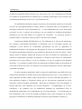
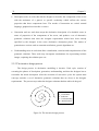
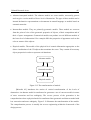
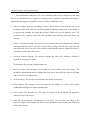
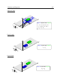
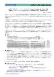
• VoluFormes. In [Chauvat 94], [Chauvat 95] is presented a declarative modeller for spatial
control. The user defines boxes in the space whose purpose is to check the growth of
forms. VoluFormes consists of two modules, Voluboites and Voluscenes. The Voluboites
module permits the user to define the boxes where the spatial control takes place. The
definition of the boxes is performed by using natural like language. The Voluscenes
module allows using growth mechanisms applied to elementary germs and creating forms
taking into consideration the spatial control boxes. The generation takes place in an
incremental manner. Each box is placed in the space and, if the user does not like the
proposed box and placement, another solution is generated. Once the current box is placed
in the space, the same process applies to the next box. Figure 2.2 presents the form
growth of VoluFormes.
Figure 2.2 Example of form growth by VoluFormes
• MégaFormes. In [Poulet et al., 96] is presented a modeller for the modelling of megalithic
monuments. The objective of this modeller is to be able to rebuild megalithic monuments
starting from a declaratory model and then visit them in a virtual way.
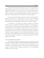
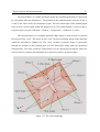
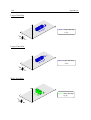
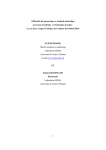
• Dem2ons. In [Kwaiter et al., 97] a declarative modeller is presented for object placement
in 3D scene surface and provides an object library and space constraints for defining the
positions of the objects. Dem2ons generate one solution per description. The modeller uses
a multi modal interface allowing descriptions by means of the voice, the keyboard (natural
language), a data glove or 3D captors informing the system of the user’s position. The
Related Research Areas
29
description is translated in an internal model made of linear constraints. The generation
engine of Dem2ons uses a linear constraint solver, called Oranos, able to process dynamic
constraints (new constraints can be added during generation) and hierarchical constraints.
Hierarchical constraints are constraints with priorities assigned by the user. Whenever
there is no solution for a given description, constraints with low priority are released in
order to always get a solution. In [Sanchez et al., 03] another approach is presenting which
applies a generic algorithm to the constraint solver. Complex scenes are produced from
basic and complex sets of constraints combined with Boolean trees. [Le Roux et al., 04]
presents a generic constraint solver based on classical constraint satisfaction techniques
and a declarative modeller for virtual 3D-environements, called DEM²ONS-NG. Figure
2.3 presents scenes created by Dem2ons.
Figure 2.3 Scenes created by Dem2ons
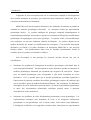
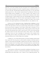
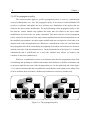
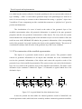
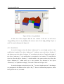
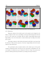
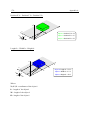
• BatiMan. In [Champciaux 98] a declarative modeller is illustrated which deals with the
architectural construction of buildings, and introduces an incremental training for solution
reduction since the generation of solutions is very time-consuming process and the
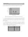
visualisation of all solutions is unrealistic. Figure 2.4 presents a building created by
BatiMan.
Figure 2.4 Examples of generated buildings by BatiMan
30
Chapter 2
• In [La Greca et al., 04] and [La Greca et al., 06] a declarative approach of parametric
surface modelling is presented which is based on B-Spline and NURBS representation.
The designer gives to the system a description, set of geometric, topological or physical
properties. The object shape is designed by manipulating several control points and the
result is a set of parametric surfaces corresponding to the user requirements.
2.2.1 General and dedicated declarative modellers
There are two families of declarative modellers one can meet according to the treated
field:
• The general purpose modellers cover a large set of possible applications, imply generality
and consider as open since they are domain-independent. The solution generation engine
can process several kinds of general properties trying to cover different domains and
incorporating extendable capabilities. On the other hand, general purpose modellers suffer
from their lack of efficiency, because of the generality of the solution generation
mechanism [Plemenos et al., 02]. MultiFormes and Dem2ons are some of the general
purpose declarative modellers.
• The dedicated modellers whose field of application is very precise. The main advantage of
the dedicated modellers is a significant precise vocabulary since the domain is almost
closed, and their efficiency because their solution generation engine can be well adapted to
the properties of the specific domain. On the other hand, it is difficult for such a modeller
to evolve in order to be able to process another specific modelling area. PolyFormes and
VoluFormes are some of the dedicated declarative modellers.
2.2.2 The declarative conception cycle
Generally speaking, the operation of a declarative modeller is based on declarative
conception cycle which is cut out in three phases, more or less sequential [Lucas et al., 95],
[Desmontils 95], [Colin et al., 97]:
• The scene description phase. A declarative modeller starts with the description of the
desired scene. The designer describes how he perceives the scene by specifying properties
Related Research Areas
31
of the scene or leaving them ambiguous. Declarative modellers use description languages
close to the natural language while others use graphical user interfaces allowing designers
to declare the structure of the desired scene. Finally, a transformation takes place
translating the description of the scene into a model, called internal declarative model.
• The generation phase. The scene generator inputs the internal declarative model and
produces a set of solutions that meet the description of the desired scene. The capacities of
the generator characterize completely the declarative modeller since this phase is the heart
of the modeller. The effectiveness of the modeller depends on the speed of treatment of
input data and its extensibility and flexibility deals with the capacity to integrate new
parameters of description whereas it is already in the course of generation.
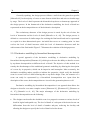
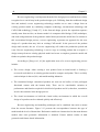
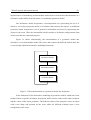
• The scene understanding phase. The scene understanding phase completes the declarative
conception cycle where the scenes solutions are visualised to the designer through a
traditional geometric modeller. Certain modellers incorporate special mechanisms form
scene understanding such as "good point of sight "static or dynamic, or information about
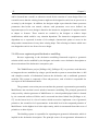
what is presented. Figure 2.5 presents the declarative conception cycle.
Scene
Description
Phase
Scene
Understanding
Phase
Generation
Phase
Figure 2.5 The declarative conception cycle
A declarative modeller permits the designer to describe the desirable scene with
specifying the properties of the components that constitute the scene. The designer rather than
describing the desirable scene, he describes the components of the scene. Therefore, a total
property describes the whole of all the components of the scene whereas a local property
describes a subset of these components. A declarative modeller must incorporate three types
of tools:
32
Chapter 2
• Description tools are tools that aid the designer to describe the components of the scene
with the assistance of a generic or specific vocabulary which reflects the various
properties that these components have. The modes of interaction are varied: natural
language, graphical user interface et cetera.
• Generation tools are tools that accept the declarative description of a desirable scene, in
terms of properties of the components of the scene, and produce a set of alternative
geometric solutions that meet the designer requirements which have been already
specified by the designer in the scene declarative description phase. The modes of
generation are various such as constrain satisfaction, genetic algorithms etc.
• Understanding tools are tools that allow visualization, selection and comprehension of the
geometric solutions. These tools may incorporate mechanisms for representing realistic
images, exploring the solution space etc.
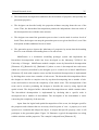
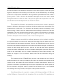
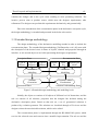
2.2.3 The iterative design process
The design process in declarative modelling is iterative. Each cycle consists of
executing the phases of description, generation, understanding, and then the designer has to
reconsider the initial description. After the execution of successive cycles the system must
converge towards a set of alternative geometric solutions that are closer to the designer
requirements. The process stops when the designer estimates that has achieved the goal.
G0
G1
G2
S0
S1
M2
U1
M1
D0
Di : Description
Gi : Generation
Si : Solutions
Ui : Understanding
Mi : Modifications
U0
Figure 2.6 The iterative design process
Related Research Areas
33
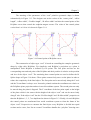
The iterative process can be represented by a spiral where in each successive iteration,
a set of geometric solutions are produced from a scene description which has been modified in
order the solutions to converge to the most recent description. Figure 2.6 illustrates the
iterative design process within the declarative modelling framework.
The concept of iterations has been discussed from many researchers. [Desmontils 95]
speaks about the concept of outline, [Liège 96] presents the spiral diagram of problem
solving, [Siret 97] organizes in cycles the sequence description, generation, forms, and [Colin
et al., 98] proposes also various working methods within the framework of the iterative design
process.
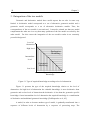
2.2.4 Levels of abstraction and levels of detail
The design process is considered as decomposable in several successive distinct stages
pointing to the initial goals [Miaoulis 02]. The design process can be viewed as a succession
of transformations between descriptions. These descriptions can be classified to a
representation hierarchy of most abstract to most concrete on levels of abstraction. In the
framework of the declarative modelling, the design process transforms a declarative
description into a set of alternative geometric solutions. Thus, two distinct levels of
abstraction are presented the declarative, which represents the most abstract, and the
geometric, which represents the most concrete.
Level of
Abstraction
Process
Evolution
Level of
Detail
Time
Figure 2.7 Evolution of the design process
34
Chapter 2
Generally speaking, the design process follows a walk from the general to specific
[Miaoulis 02]. In the majority of cases we start from an initial idea and arrive to details stage
by stage. The levels of detail represent the hierarchical top-down or bottom-up approach of
the design process. In the framework of the declarative modelling, the levels of detail are
represented on the decomposition tree of the declarative description
The evolutionary character of the design process is traced by the axis of time, the
levels of abstraction and the levels of detail [Miaoulis et al., 00]. The design process is
defined as a succession of similar stages for reaching the final model and can be represented
as a spiral in a three-dimensional space. An initial idea serves as a starting point. As time
evolves the level of detail increases while the level of abstraction decreases until the
achievement of the final model. Figure 2.7 illustrates the evolution of the design process.
2.2.5 Declarative modelling by hierarchical decomposition
A special approach of the declarative modelling is declarative modelling by
hierarchical decomposition [Plemenos 91], which gives the user the ability to describe a scene
by top-down decomposition at different levels of detail. The objective of this method is to
remedy the disadvantages of the traditional geometric modelling by allowing the description
of a scene by its properties, which can be imprecise and incomplete. More accurately, the
declarative modelling makes possible to indicate the properties, which verify the desirable
scene in several levels of detail allowing thus a top-down design. Thus, the structure of a
scene can easily be represented by a hierarchical decomposition tree. Apart from the
description of the scene, the decomposition tree is used in the generation phase as well.
Declarative modelling by hierarchical decomposition is an approach that allows the
designer to describe even more complex scenes [Plemenos 91], [Plemenos 93], [Plemenos et
al., 97], [Bonnefoi et al., 02]. The major advantages of the declarative modelling by
hierarchical decomposition are the following:
• The designer can describe the desirable scene in a progressive manner at various levels of
detail in logical and spatial way. The level of detail of a sub-part of the desired scene can
differentiate from the level of detail of another sub-part, enforcing the locality and
allowing the designer to specify the levels of detail as he/she deems.
Related Research Areas
35
• The hierarchical decomposition authorises the factorisation of properties and specially the
placement properties.
• The designer can describe locally the properties without worrying about the rest of the
scene. Thus, the hierarchical decomposition permits the independence between nodes of
the decomposition tree with the same ancestor.
• The designer can control the generation process since it can be made in various levels of
detail. Thus, the designer can stop the generation process at a given detail level, even if the
description includes additional levels of detail.
• The generation process insures the inheritance of properties by means that the bounding
box of a scene includes all bounding boxes of its sub-scenes.
MultiFormes is a declarative modelling prototype system and implements the
hierarchical decomposition which has been developed at the laboratory XLIM of the
University of Limoges. MultiFormes models complex scenes by hierarchical decomposition
[Plemenos 95], [Bonnefoi 99], [Ruchaud 01] where a scene is decomposed into sub-scenes
which are recursively described by the designer up to a certain level of detail. MultiFormes
[Plemenos 95] deals with complex scenes and the hierarchical decomposition is implemented
by dividing these scenes into a number of sub-scenes. The hierarchical decomposition allows
the designer to describe a complex scene by top-down decomposing into a number of subscenes and results to decrease the complexity of the whole scene. The decomposition of the
scene can be recursive permitting the designer to describe the scene by using logical and
spatial criteria. The designer builds a hierarchical decomposition tree which contains nodes.
The hierarchical decomposition is implemented by declaring that a specific node is
decomposed into a number of descendants. The description of the descendants is easier
concerning the complexity of the ancestor.
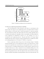
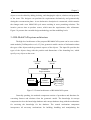
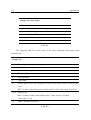
Apart from the logical and spatial decomposition of the scene, the designer specifies
the properties and relations that are necessary from his point of view. A property to a node
operates as a constraint and obliges the object, to respect that specific property, since it will
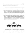
participate to the generation phase. Figure 2.8 illustrates a typical decomposition tree along
with the relations and the properties. The example is adopted from [Plemenos 95].
36
Chapter 2
Residence
House is on the left of Garage
House is higher than large
House is higher than wide
Walls
Garage is 70% top rounded
House
Garage
Roof
Roof is on the top of Walls
Roof is 70% top rounded
Figure 2.8 A typical example of a decomposition tree
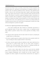
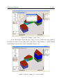
The generation phase of MultiFormes produces objects which are described by their
bounding boxes. Each of these bounding boxes is described by a starting position, in terms of
X, Y and Z coordinates, and a displacement vector defining the width, the height and the
depth of the associated bounding box. Each bounding box is described by at least six numeric
variables. Besides, some other relevant information is associated like the colour or the texture
of the object. MultiFormes associates the properties with the starting position and the size of
the bounding box of the object. A workspace is defined, and all bounding boxes of objects
take place in this workspace. MultiFormes uses a numeric constraint solver and several
researchers have worked on the aforementioned solver [Tamine 95], [Plemenos et al., 97],
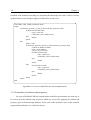
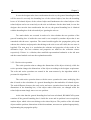
[Bonnefoi 99]. Figure 2.9 illustrates different solutions of MultiFormes.
Figure 2.9 Solutions of MultiFormes
Related Research Areas
37
MultiFormes has been designed to produce all possible geometric solutions that satisfy
the constraints which have been declared by the designer in terms of properties. Therefore, the
predefined properties operate as constraints and reduce the range of the values that the starting
position and the size of the bounding boxes can take. The set of different geometric solutions
is produced from an exhaustive exploration of all permitted values that can be applied on the
starting position and the size of each bounding box within a specific workspace. Besides, the
number of the predefined properties along with the complexity of the described scene affect
the generation time of the geometric solutions. Special suggestions for improvement of the
description and generation phase of MultiFormes take place in [Bonnefoi 99] and [Ruchaud
01].
Fribault in [Fribault 98], [Fribault 04] proposes and implements an information system
associated with a declarative modeller for the assistance of habitation edifices. The necessary
properties are defined for describing a building along with the assembly rule utilised in the
architectural design. According to the declarative modelling, the description phase evaluates
the scene description for coherence and the generation phase incorporates a resolution engine,
which has been implemented within the GNU-Prolog environment, and deals with the
constraints resolution on finite domains.
2.2.6 MultiCAD system architecture
MultiCAD [Miaoulis et al., 96], [Miaoulis et al., 98] is a proposed multimedia CAD
system, liberated of geometric inflexibility, which will be used for the creation of scenes.
MultiCAD is a software architecture framework for the development of multimedia and
intelligent information systems in order to support declarative design processes [Miaoulis 02].
The MultiCAD system is based on the declarative modelling of scenes by hierarchical
decomposition. The objective of this method is to remedy the disadvantages of the traditional
geometric modelling by allowing the description of a scene by its properties, which can be
imprecise and incomplete [Lucas et al., 90], [Plemenos 91], [Plemenos 95]. More accurately,
the declarative modelling makes possible to indicate the properties, which verify the desirable
scene in several levels of detail allowing thus a top-down design.
38
Chapter 2
The design environment of MultiCAD features a rich set of modules. These include
alternative modules for solution generation using constraint satisfaction programming
[Bonnefoi et al., 02], [Plemenos et al., 97] or genetic algorithms [Vassilas et al., 02], [Makris
05] as well as modules responsible for introducing architectural knowledge [Ravani et al., 03],
representation of architectural styles [Makris et al., 03], collaborative design [Golfinopoulos
et al., 04], and intelligent user profile [Plemenos et al., 02], [Bardis et al., 04], [Bardis et al.,
05]. The main disadvantages of the constraint satisfaction programming search strategy is the
exhaustive search which leads to unacceptably long times in relatively large problem spaces,
the inability to interact with the designer and derive solutions that satisfy the designer
aesthetics. [Makris 05] proposes a generation engine based on generic algorithms and handles
with limitations the latter disadvantage while [Bonnefoi et al., 02] deals with the first
disadvantage.
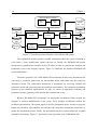
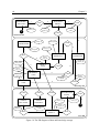
The directions of MultiCAD software architecture framework are defined through a
research project supported by the Laboratory XLIM of the University of Limoges along with
the Intelligent Information Systems Engineering Team of Informatics Department of TEI
(Technological Education Institute) of Athens. MultiCAD is a multi-layered architecture that
comprises the following main layers [Miaoulis 02]:
• The interface layer incorporates functions such as intelligent visualisation of scene models
and documents, creation and editing of models and description, formulation of the request
(traditional formulations of SQL, spatial SQL or free text search), navigation and browsing
of databases, acquisition and editing the different types of knowledge and information,
application and interaction control.
• The process layer comprises functions such as generation or understanding between the
different levels of models, converting the different types of the same level’s models.
• The information and knowledge management layer is used for structuring, management,
searching and exploitation of the different databases.
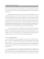
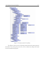
MultiCAD follows the declarative conception cycle where in the description phase the
designer describes the desired scene by defining the scene’s decomposing objects, their
properties and relations in many ways:
Related Research Areas
39
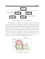
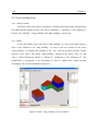
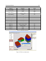
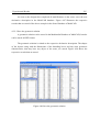
• Tree-formed representation. This form explicitly represents the hierarchical decomposition
of the scene. Figure 2.10 presents the working space of MultiCAD.
• Text-formed representation. It is expressed in a formal Prolog-like language [Plemenos 95]
representing the internal declarative representation of the scene.
• Representation in an object-relational database [Miaoulis 02]. The scene’s description is
stored as an assembly of objects having properties, and being related to each other through
relations.
Figure 2.10 The working space of MultiCAD
MultiCAD incorporates an object-relational database [Miaoulis 02], which consists of
five logical inter-connected databases:
• The scene database contains information describing the scene models (internal declarative
representation models, relations between the composing objects et cetera).
• The multimedia database contains all types of documents related to the project (geometric
models, geometric primitive shapes, multimedia information et cetera).
40
Chapter 2
• The knowledge base contains all the necessary information about entities type, their
properties along with their relations.
• The project database deals with data concerning planning, financial and other special
aspects of each project.
• The concept database [Ravani et al., 04] includes concepts representations.
The Scene database is configured following the Scene Conceptual Modelling
Framework (CMF) [Miaoulis et al., 00], where the description of a scene contains entities,
such as:
• objects defined by their properties, simple or generic ones, a single object corresponds to
the existence of a real 3D object with well-defined characteristics and properties, a generic
object covers a group of simple objects with properties in common,
• three types of relations between objects: meronymic relations which are used to describe
physically or conceptually part-of relations (“is-part-of”, “is-included-in”), spatial
organization relations which are used to specify the relationships between objects (“nearby”, “on-left”, “higher-than”) and reflective relations which are used to describe
comparisons of the same object (“higher-that-large”, “higher-than-deep”),
• and properties that characterise and describe the objects (“is_tall=’high’”, “colour=’green’”
et cetera).
The generated scene solutions are visualised through their geometrical representation:
Bitmaps [Miaoulis 02], VRML [Vassilas et al., 02], and AutoCAD designs [Makris et al., 03].
The designer can evaluate the solutions according to his/her criteria either by selecting the
best ones or by setting a score to each of them [Vassilas et al., 02].
2.3 Feature-based modelling
Feature-based modelling is used for modelling products the last years. One of its main
advantages over the geometric modelling is the ability to associate functional and engineering
information to shape information in a product model. The basic entity of a feature model is
Related Research Areas
41
the feature, defined as a representation of shape aspects of a product that are mappable to a
generic shape and are functionally significant for some product life-cycle phase. In general,
feature model is the elementary part of the products. These parts define in turn assemblies
which they define feature models. Typical examples of features are holes, slots, pockets,
protrusions, et cetera for general mechanical components.
There are many types of features and can be categorized according their function,
complexity, and level of detail of the geometric description. According to their function,
features are categorized into form features, material features, and pattern features.
Besides, features are distinguish by their degree of complexity into elementary
features, which are basic simple and cannot be decomposed into more simple features, and
compound features [Bronsvoort 93], which are composed of several other features.
Furthermore, there are features which are described by parameters, they are not
evaluated into a precise geometric description, their exact shape is not represented and it is
merely implied. Explicit features have their shape explicitly described by a geometric model
while their resulting geometry is evaluated [Bronsvoort 93].
Features use properties for their definition. Intrinsic properties refer to the fact that
they affect only the feature itself. Extrinsic properties affect and depend on the properties of
other features. Other characteristic properties of the features are derived and non-derived
properties. Derived properties are such their values do not determined by the user, but derived
from other features.
It has been often remarked that feature modelling is nothing more than advanced
geometric modelling, only offering parametric and constraint-based modelling facilities, in
addition to the normal geometric modelling facilities.
Almost all current feature modelling systems are parametric, history-based systems,
using a boundary representation as main geometric representation. History-based modelling
systems are procedural systems that keep track of information about each modelling operation
performed such as the type of feature created, its parameter values and its positioning. The
sequence of modelling operations creates the model history, completely determines the
42
Chapter 2
resulting boundary representation. The creation of a feature produces the shape imprint
characteristic of its feature type. Feature instances can be modified by specifying new values
for their parameters, or be deleted from the model. This is achieved by modifying or deleting
the respective feature creation operation in the model history. The new feature model is
evaluated by sequentially re-executing the operations in the model history. In figure 2.11 a
boundary model is illustrated which consists of a base block, a blind hole and a protrusion.
The example is adopted from [Bidarra 99].
Figure 2.11 A boundary model
According to [Bidarra 99] history-based systems suffer from the strong dependency on
the chronological order of the feature creation, the limitations of constraint solving and the
historical evolution of the entities in the evaluated boundary model.
The current feature-based modelling approach has the following drawbacks
[Bronsvoort 01]:
• The meaning, or semantics, of features is poorly defined, limiting the capability of
capturing design intent in the model. Moreover, semantics are often not adequately
maintained during modelling. An answer to this drawback is given by [Bidarra 99] where
the definition of the semantic feature modelling is taken place. In semantic feature
modelling the feature specification is done in feature classes which are structured
descriptions of all properties of a given feature type. A semantic feature model is
developed to represent a product and consists of a feature dependency graph, which is a set
of interrelated features and constraints, and the geometric representation. The validity
maintenance monitors each modelling operation in order to assess the conformity of all
features in the semantic feature model.
Related Research Areas
43
• The product development phases lack product models with multiple feature views. In
general, current only form feature views are supported by multiple-view feature modelling
systems.
• The feature modelling systems does not support yet a collaboration environment of several
users in product development.
On one hand, there are similarities between feature-based and declarative modelling.
The main similarity is based on the fact that both modelling approaches permit the designer to
describe the desired scene in an abstract way. Besides, both offer constraint-based techniques
through parameters in feature-based modelling and through property specification in
declarative modelling. Another similarity is the object-oriented nature, where the designer
approaches the design itself through objects instead of handling geometric primitives.
One the other hand, feature-based has differences with declarative modelling. A
boundary model needs all relevant geometric information in order to be constructed while
declarative modelling can handle the imprecise information. In addition, declarative
modelling produces a set of alternative solutions while feature-based modelling produces just
one geometric solution. Feature-based systems are usually history-based since they keep track
of the designer operations. Changing the order of the designer operations may lead to different
boundary model. Declarative modelling incorporates a solution generator, which produces
solutions according to the property specifications despite of the order.
2.4 Reverse engineering
Engineering is the process involved in designing, manufacturing, constructing, and
maintaining of products, systems, and structures. At a higher level, there are two types of
engineering: forward engineering and reverse engineering.
Generally speaking reverse engineering is the process of taking something (a device,
an electrical component, a software program, et cetera) apart and analyzing its workings in
detail, usually with the intention to construct a new device or program that does the same
thing without actually copying anything from the original. In other words, reverse engineering
is the process of analyzing a subject system to (i) identify the system's components and their
44
Chapter 2
interrelationships and (ii) create representations of the system in another form or a higher
level of abstraction [Chikofsky et al., 90].
Forward engineering is the traditional process of moving from high-level abstractions
and logical, implementation-independent designs to the physical implementation of a system
[Chikofsky et al., 90]. Reengineering (also known as renovation and reclamation) is the
examination and alteration of a subject system to reconstitute it in a new form and the
subsequent implementation of the new form. Reengineering is the modification of a system
that takes place after it has been reverse engineered, generally to add new functionality.
Reverse engineering is very common in such diverse fields as software engineering,
entertainment, automotive, consumer products, microchips, chemicals, electronics, and
mechanical designs. In some situations, designers give a shape to their ideas by using clay,
plaster, wood, or foam rubber, but a CAD model is needed to enable the manufacturing of the
part. As products become more organic in shape, designing in CAD may be challenging or
impossible. There is no guarantee that the CAD model will be acceptably close to the sculpted
model. Reverse engineering provides a solution to this problem because the physical model is
the source of information for the CAD model.
Another reason for reverse engineering is to compress product development time.
Rapid product development refers to recently developed technologies and techniques that
assist manufacturers and designers in meeting the demands of reduced product development
time. By using reverse engineering, a three-dimensional product or model can be quickly
captured in digital form, re-modelled, and exported for rapid prototyping/tooling or rapid
manufacturing.
2.4.1 Reverse engineering in scene modelling
As mentioned before, the design process can be viewed as a successive transformation
between models. These models can be classified into a representation hierarchy of most
general to most specific according to the levels of abstraction. Usually, we start the design
process indicating a conceptual model which is transformed into specific model. Within the
framework of MultiCAD, several scene model types exist according to levels of abstraction
[Miaoulis 02]:
Related Research Areas
45
• Abstract/conceptual models: The abstract models are scene models, necessarily generic
and can give a series models of lower level of abstraction. The type of these models can be
internal declarative representations or documents in natural language or models based on
semantic networks.
• Intermediate models: They are primarily geometric models. These models are concrete
from the point of view of the geometric properties of objects, of their composition and of
their of space arrangement. Geometrical models can produce several different models of
the lower level of abstraction if for example differ the properties of appearance such as the
color or texture of the objects.
• Physical models: The models of the physical level contain information appropriate to the
direct visualization of the 3D objects that constitute the scene. They contain all necessary
object properties in order to represent real situations.
Abstract models
Geometric models
Physical models
Figure 2.12 The transformation of models
[Miaoulis 02] introduces the notion of vertical transformation of the levels of
abstraction. An abstract model is transformed or generates a set of concrete models in terms
of more concretion and less ambiguity. The reverse process of the generation is the
comprehension where a physical model is transformed into geometric and abstract model with
less concretion and more ambiguity. Figure 2.12 illustrates the transformation of the models.
The comprehension process is actually the reverse engineering within the framework of the
design process.
46
Chapter 2
Reverse engineering is an important branch of the design process and has been widely
recognized as a crucial step in the product design cycle. Differing from the traditional design
idea and method, reverse engineering technology enables one to start a design from an
existing product model by combining computer technology, measurement technology and
CAD/CAM technology [Varady 97]. In the forward design process the operation sequence
usually starts from an idea, an abstract model via computer-aided design (CAD) techniques,
and ends with generation of the geometric model that represents the initial idea. In contrast to
this conventional design process, reverse engineering represents an approach for the new
design of a product that may lack an existing CAD model. In the process of the product
design and research, the use of reverse engineering will reduce the production period and
costs. Reverse engineering technology is not to copy an existing product but to acquire a
design concept from an existing physical model and create a complete geometric model and
further to optimize the product design.
According to [Peng et al., 01] the application areas of a reverse engineering process
include:
• The reverse design: either creating a new product from an initial model or feeding a
recovered result back to an existing product model to compare and update. This is a widely
used technique in the tool, die, and mould-making industries.
• The customized design: customized products are worn on our bodies, or have prolonged
functional contact with the human body. There can be considerable variation in
performance and function required for this kind of products and it is, therefore, essential to
involve the customer in the design process.
• The virtual environment: to build the virtual reality environment in which the overall
design of a product can be evaluated quickly and effectively.
Reverse engineering and modelling techniques can be combined into tools as meant
from the current literature. Figure 2.13 presents the correspondence between the type of
models and the levels of abstraction. Declarative models are characterised as the most abstract
models since none geometric information is included. Feature models consist of both
geometric and feature-based information.
Related Research Areas
47
Levels of Abstraction
Declarative
models
Feature
models
Geometric models
Physical models
Figure 2.13 Models according to the level of abstraction
2.4.2 Reverse engineering and geometric modelling
The 3D reconstruction is a huge field and of course there is a vast literature on the
specific subject. The input of reverse engineering process is the physical object of interest,
while the output is its CAD model: either a surface representation or a volume representation.
The conversion between surface and volume model can be done by mature algorithms such as
voxelization and marching cube algorithms. Surface representations and fitting methods for
reverse engineering are summarized in [Chivate et al., 95], [Petitjean et al., 02]. In
conventional reverse engineering processes, 1D (point cloud data) or 2D (range images)
sampling data of the surface of interest is acquired by digitizing devices (CMM, laser scanner,
etc.) or photographing devices (CCD camera, ICT, MRI, etc.), respectively.
Reverse engineering methods diverges from data measuring strategies. Commonly
used data acquiring devices can be categorized into contact or non-contact devices. Contact
type devices are generally more accurate but slow in data acquisition, and vice versa for noncontact type devices. According to whether the probe is held by operators, contact devices can
be further divided into two classes: automatic devices and manually holding devices. The
common drawback of contact devices is that they may deform or even damage the surface of
the object being digitized because of the direct physical contact. Non-contact devices measure
the point coordinates using distance measuring methods, such as laser scanner and sonar. The
48
Chapter 2
merit of non-contact distance measuring methods is high scanning speed. The accuracy of this
type of digitizers is dependant on surface reflectance, the light paths to the sensor, and the
material (transparent or semitransparent et cetera).
In engineering areas such as aerospace, automotives, shipbuilding and medicine, it is
difficult to create a CAD model of an existing product that has a free-form surface or a
sculptured surface. In these cases, reverse engineering is an efficient approach to significantly
reduce the product development cycle [Zhang 03]. It is often used in cases such as the
following:
• Where a prototype of the final product has been modelled manually and therefore no CAD
model of the prototype exists, e.g. clay model in automotive industry.
• Where a CAD is introduced in a company and all existing products must be modelled in
order to have a fully digital archive. Particularly, the CAD model of a complex shaped part
is modelled because it is difficult to create its CAD model directly.
• Where complex shaped parts must be inspected and therefore the reverse engineering
model created will be compared to an existing CAD model.
In medical engineering a representative example of reverse engineering is the
customized artificial joint design [Lina et al., 05], where in order to meet the requirements and
to reduce the production cycle and cost, a method is presented to generate the complex
surface of an artificial knee joint by co-ordinate measuring machine from the normative
prosthesis, and form the model data base. The method gets the better data points among point
cloud data and then, the free-form surfaces are constructed from the point cloud data using the
reverse engineering software —Surfacer. The solid CAD model of the artificial knee joint is
created from the surfaces by extension, intersection. These models formed the data base of the
prosthesis, in which we can select a suitable kind of artificial knee joint model to customize
for the patient. It is only needed to change the local data of the corresponding CAD model to
meet the different requirements of the patient.
In [Stamati et al., 05] is introduced the ByzantineCAD, a geometric parametric CAD
system for the design of pierced jewellery. The ByzantineCAD is an automated parametric
Related Research Areas
49
system where the design of a piece of jewellery is expressed by a collection of parameters and
constraints and the user’s participation in the design process is through the definition of the
parameter values for reproducing traditional jewellery. The design of the traditional pierced
jewellery is based on the voxel-oriented feature-based Computer Aided Design paradigm
where a large complex pierced design is created by appropriate placing elementary structural
elements. The final piece of jewellery is produced by applying a sequence of operations on a
number of elementary solids. An algorithm for scaling pierced patterns and designs has been
introduced to enlarge pierced figures without altering the size of the structural elements used
to construct them. The reverse engineering process is focused on providing manually the
elementary structural elements to the system instead of capturing these elements from existing
artifacts and using them to reproduce the originals.
2.4.3 Reverse engineering and feature-based modelling
In the feature modelling field, object semantics are semantically represented for a
specific application domain. In other words, a semantic feature is an application-oriented
feature defined on geometric elements. There are three approaches for building a feature
model:
• the design by feature approach creates the feature model of an object by composing the
available features in a feature library,
• the feature recognition approach recognizes various features from a geometric model of an
object according to the feature templates defined in a feature library,
• the feature conversion approach enables the definition of other feature models based on a
feature model of a product already created. The new feature model corresponds to
alternative views of the same product. Feature conversion is a technique that defines the
basis for multiple-view feature modelling systems [Bronsvoort 01].
In order to create a feature model of an object from a point cloud, the embedded
features must be recognized. These features are then used to constrain the fitting process.
Feature recognition methodologies can be classified into two major categories: surface
recognition and volume recognition. The main difference between these two categories is
50
Chapter 2
mainly due to the feature definition and object description in the recognition method. The
features and object description in the surface recognition category are expressed in terms of a
set of faces and edges. The graph-based method discussed by [Little et al., 98], syntax-based
method proposed by [Li 88], rule-based method discussed by [Henderson 84] and neural
network method raised by [Prabhakar et al., 92] are examples of this category. On the
contrary, the features and object description are defined in terms of primitives in the volume
recognition category. Typical examples are the convex hull algorithm by [Kim 92], hint-based
reasoning method by [Han et al., 98] and curvature region approach by [Sonthi et al., 98].
Although many different methods are proposed to recognize the features from an object
description, only regular shaped objects can be handled [Little et al., 98], [Sonthi et al., 98].
In [Au et al., 99] is discussed the issues of applying feature technology to reverse
engineering technology of a mannequin. According to that, the feature model of a mannequin
consists of the major features of the torso for garment design, and the features are recognised
from the point cloud by comparing it with a generic feature model. Association is set up
between the point cloud and the mannequin feature. Fitting the generic model to the point
cloud yields the mannequin feature model of a specific person. This is achieved by optimizing
the distance between the point cloud and the feature surface, subject to the continuity
requirements. However the task of matching the critical points is done manually. Since
surface fitting forms the shape of the human model it is hard to capture details of the
mannequin and the process of surface fitting is time consuming.
In [Wang et al., 03] a feature-based approach is presented of building a human model
from a point could. The noisy points are removed and the orientation of the human model is
adjusted. A feature based mesh algorithm is applied on the point cloud to construct the mesh
surface of a human model. The semantic features of the human model are extracted from the
surface. The advantages of the specific approach are the topology of the human models
preserved, more details can be included in the feature human model, and the algorithm seems
more efficient.
Apart from these, in [Fisher 04] is presented the contribution of knowledge in reverse
engineering problems. In particular, it is discussed the applicability of domain knowledge of
standard shapes and relation ships to solve or improve reverse engineering problems. The
Related Research Areas
51
problems considered are how to enforce known relationships when data fitting, how to extract
features even in very noisy data, how to get better shape parameter estimates and how to infer
data about unseen features. Even if the current work focuses on the reconstruction, it shows
that the applicability of domain knowledge, in the general framework of the knowledge-based
approach, plays a significant role in the reverse process. The paper explores techniques, made
at Edinburgh University, to improve reverse engineering of objects from three-dimensional
(3D) point data sets by applying constraints on feature relationships in manufactured objects
and buildings in order to improve the recovery of object models, by applying general shape
knowledge for recovery even when data is very noisy, sparse or incomplete. Many of these
recovery problems require discovery of shape and position parameters that satisfy the
knowledge-derived constraints. Evolutionary search methods can be used to do this search
effectively.
The research from the University of Utah [Thompson et al., 99], [de St Germain et al.,
97] who have also been investigating constrained reconstruction of parts from 3D data sets,
particularly parts with pocket profiles. They categorized the types of engineering knowledge
as domain-specific and pragmatic, and functional constraints. They exploit this knowledge to
select surface types and manufacturing actions. Thus, with some user assistance, planar
features that bound pockets are found. The contour that is swept to form the pocket can then
be found automatically. Shape and positional constraints are represented and solved in a
manner similar to [Fisher 04].
The research from the University of Cardiff [Benkó et al., 02], [Benkó et al., 01]
exploits designed-in relationships to improve reconstruction. In their case, a much larger set
of relationships was explored, and the constraints arising from the relationships were used to
reduce the dimensionality of the reconstruction parameter space. A sequential numerical
constrainment process is used, which allowed them to detect and automatically reject
inconsistent constraints. A nice alternative to fitting tangential and blend surfaces was to
parameterize swept 2D features, with the cross-section of the inter-surface join/blend as the
2D feature.
A special branch of reverse engineering is the reverse design where in [Vergeest et al.,
05] during the reverse design of free-form shapes, existing shapes or features can be extracted
52
Chapter 2
and be inserted into a model, or otherwise reused for the creation of a new design. Here it is
essential to note that the existing features might not be designed as such, but are perceived as
an entity by the designer. In addition, the designer might expect that the feature possesses
parameters that he/she can control, whereas such parameters were never defined. An
important aspect of reverse design is therefore the interactive assignment of complex controls
to shapes or features. These controls are needed by the designer to achieve shape
modifications, which could be very situation dependent. The interactive assignment can be
dependent on, or expressed in terms of, for example, characteristic points or curves in the
shape under construction or in any other existing shape. This referring to features which were
not designed as such is one form of reverse design.
2.4.4 Reverse engineering and declarative modelling
Reverse engineering in the declarative modelling framework acquires a geometric
solution which can be modified by the designer and results a new declarative description to
the next iteration of the declarative conception cycle.
The XMultiFormes project [Sellinger 98], [Sellinger 95] is a previous work that tries
to integrate the two modellers by using a special interface system to ensure that there is full
and complete transfer of information between the declarative and a traditional geometric
modeller. This system is composed of four sub-processes, each of which is responsible for
one aspect of the information transfer.
The geometric convection process translates the geometric representation generated by
MultiFormes into one that is more suited to interactive modelling. The principal geometrical
entity used by solution generator of MultiFormes is a closed parallelepiped which is formed
by six connected surfaces of Bézier and is converted into three linked lists [Sellinger et al.,
97]. At the lowest level is a list of vertices which are used to implement a set of geometric
primitives, the second level of representation. At the third level is the compound primitive of
MultiFormes. At the highest level is the object entity, which is constructed from either a set of
primitives or other objects.
The labelling system is responsible for capturing non-geometric information, which is
implied in the declarative description. The principle source of non-geometric information is
Related Research Areas
53
the sub-scene names in the declarative description. These manes typically contain an explicit
high-level description of the meaning of the sub-scene, and are maintained by the labelling
system as a set of properties called labels. After a geometric representation has been created a
special process is used to traverse the hierarchical description of the scene and to match
decomposed sub-scene names to labels. This process requires the cooperation of the user
since the label list must be adapted to the set of sub-scene names.
The geometric-to-declarative representation conversion process converts a geometric
instance to declarative description by identifying all objects without parent, determining if the
bounding boxes overlap and, if so, decompose the hierarchical objects, generating a scene
hierarchy using a binary sub-scene agglomeration and describing each sub-scene and their
relationships. The scene inclusion process provides a means for the inclusion of previously
generated scenes in a declarative description. The designer can associate a sub-scene in the
declarative description with an existence scene or a list of existing scenes.
Sellinger connects successfully a traditional geometric with a declarative modeller,
gives special emphasis on retrieving the appropriate knowledge from the designer and gives
special attention on man machine interaction.. However, the XMultiFormes project does not
incorporates any database management system, which means that the designer is obligated to
execute the whole design process at once, and can not store the most desired geometric
solutions for further manipulation. The lack of a database management system also affects the
update on the relationships since the available relationships are hard coded obviously, and
inhibits the designer to work on different domain other than the architectural design of
buildings.
The inclusion process of XMultiFormes provides to the designer the only ability to
modify declaratively the scene by including a sub-scene in the declarative description with an
existence scene which makes the process inflexible for further modifications. Besides, the
geometric to declarative representation process requires computation time and the quality of
the new declarative description, which is produced in each iterative cycle, is not evaluated
since Sellinger does not present any convergence of the geometric solutions.
Generally speaking, the cooperative computer aided design paradigm (CCAD) was
used by Sellinger as a framework for the integration of the two modellers. This paradigm was
54
Chapter 2
originally developed to provide an interactive generative geometric modelling system with a
cyclic design path and it is well adapted to the declarative modelling. The CCAD paradigm is
based on the assumption than the system can not create perfect geometric solutions, but
superior designs can be generated by allowing the designer to guide the system through
successive rounds.
2.5 Discussion
Engineering is involved in designing, manufacturing, constructing, and maintaining of
products, systems, models and structures. At a higher level, there are two types of
engineering: forward engineering and reverse engineering.
Forward engineering is the traditional process of moving from high-level abstractions
and logical designs to the physical implementation of a system or product. Reverse
engineering can be viewed as the process of analyzing a system/model in order to identify the
sub-components and their interrelationships, create representations of the system/model in
another form or a higher level of abstraction and reengineer the physical representation of that
system/model.
In designing, reverse engineering process permits the transformation of one model into
another one. In the framework of geometric modelling, reverse engineering is used in order to
construct a 3D model from a physical model. Furthermore, reverse engineering in featurebased modelling is used in order to extract features from feature instances of the geometric
model.
In declarative modelling approach, reverse engineering is used to transform the
geometric model into a declarative model. Sellinger’s thesis presents a first attempt of
coupling a traditional geometric modeller with a declarative modeller and is based on
interactive modelling. Sellinger’s approach is traditional, cooperative and gives a special
emphasis on man-machine interaction since it gathers all relevant information form the
designer in order to convert a geometric into declarative model.
There is room for further improvement by exploiting domain-specific knowledge and
using an object-oriented approach which facilitates the designer to manipulate a selected
Related Research Areas
55
scene, states his/her requirements either in geometric or declarative way during the iterative
design process and after a few iterations the designer gathers all promising geometric
solutions. Thus, we concentrate on settling the high-level reverse engineering in declarative
modelling framework. The knowledge-based reverse engineering approach is presented in
Chapter 3.
Chapter 3
Thesis proposal and implementation
The objective of this chapter is to present a deep overview of the thesis proposal and
implementation. The main hypothesis of this thesis is to integrate the two models, the
declarative and geometric. The integration takes place in a new defined phase in the
declarative conception cycle, the reconstruction phase. RS-MultiCAD has been designed in
order to handle the integration of the MultiCAD declarative modeller with a traditional
geometric modeller. RS-MultiCAD implements the knowledge-based reverse engineering
approach in order to transform a geometric solution, which has been generated by MultiCAD,
into a declarative model.
In the next sub-section the architecture of the proposed RS-MultiCAD system is
presented. First of all, this sub-section starts with the presentation of the data and knowledge
storage and indicates the interrelations between the databases. A special attention is given on
describing the dynamic stratified representation. The stratified representation overcomes the
problems of capturing geometric and declarative information by incorporating a declarative
and a geometric layer. RS-MultiCAD system semantically understands a selected scene by
exploiting the knowledge base of MultiCAD and permits a series of scene modifications to
designer in order to alter the selected scene. The stratified representation absorbs the designer
modifications by activating a propagation policy which correctly determines the transition of
a selected scene from one state to another. Besides, RS-MultiCAD system provides the
possibility to the designer to determine how the resultant declarative description is
constructed which will be passed to the declarative description phase, in the next iteration of
MultiCAD.
The last sub-section is dedicated to the implementation of RS-MultiCAD. It presents
the geometric representation, the main algorithms that RS-MultiCAD prototype incorporates,
such as the knowledge extraction and the construction of the stratified representation. Finally,
this sub-section presents the algorithm for the manipulation of the scene modifications along
with the construction of the resultant declarative description.
58
Chapter 3
3.1 Integration of the two models
Geometric and declarative models have useful aspects but are also in some way
limited. A declarative model corresponds to a set of alternative geometric models and a
geometric model corresponds to a set of alternative declarative models. Thus, the
correspondence of the two models is not univocal. It must be pointed out that one model
complements the other one in a way that many problems of the one model are solved by the
other model. For this reason the integration of the two models results in an extremely
powerful design tool.
Level of
Abstraction
High Level
Declarative
Modelling
Intermediate
Level
Geometric
Modelling
Low Level
Type of Acquired
Knowledge
Figure 3.1 Type of acquired knowledge according to level of abstraction
Figure 3.1 presents the type of the acquired knowledge relative to the level of
abstraction. On high-level of abstraction the valuable knowledge is more declarative than
geometric and on low-level of abstraction the declarative is less than the geometric specific
knowledge. On an intermediate level of abstraction the acquired knowledge is a combination
of declarative and traditional geometric knowledge [Golfinopoulos et al., 05].
A model, in order to become another type of model, is gradually transformed into a
sequence of different levels of abstraction by a sequence of processing steps. The
Thesis Proposal and Implementation
59
imperativeness of introducing an intermediate model derives from the fact that the nature of a
declarative model differs from the nature of a traditional geometric model.
Our declarative model incorporates a decomposition tree representing the level of
details, a set of object properties and a set of relations that connects the objects. A traditional
geometric model incorporates a set of geometric information necessary for representing the
objects of the scene. Thus, the intermediate model consists of declarative and geometric data
of the scene that are connected properly.
Figure 3.2 shows schematically, the transformation of a geometric model into
declarative via an intermediate model. The arrows that connect the different models show the
reverse design within the declarative modelling framework.
Declarative Model
Intermediate Model
Geometric Model
Figure 3.2 The transformation of a geometric model into declarative
In the framework of the declarative modelling all geometric models, which have been
produced from a specific declarative description, differ onto the values of the object relations
and the values of the object properties. The different values of the properties cause an object
with a new shape and position on the scene while the different relations cause a new
arrangement of the scene.
60
Chapter 3
3.2 Reconstruction phase
The declarative conception cycle of MultiCAD system architecture (see section 2.2.6)
can be extended to an iterative process by using a reconstruction phase [Golfinopoulos et al.,
05] where the scene is semantically understood and refined by adding more detailed
descriptions in successive rounds of declarative design process. In this case undesirable
designs are cut from the set of solutions, the size of the solution set after each round of
generation can be reduced and after a few iterations the designer gathers all promising
solutions. Under the reconstruction phase an intermediate model is built in order to handle all
the necessary information concerning the declarative and geometric side of the scene. The aim
of the reconstruction phase is to receive a geometric model, provide a new declarative model
enhanced with geometric constraints to the scene declarative phase and also permit the
designer to change the geometry of the scene by modifying the geometric aspects of the
objects. These changes are semantically checked and the intermediate model is updated.
Generation
- Selection
extends
Scene
Description
extends
uses
Data &
Knowledge
Storage
uses
uses
Designer
Solution
Understanding
uses
extends
extends
Reconstruction
Figure 3.3 The new declarative conception cycle
Figure 3.3 presents the new declarative conception cycle by placing the new
reconstruction phase in a UML use case diagram. The cycle starts with a declarative
description, which produces a set of geometric solutions. The solutions are visualized and the
designer selects the most desirable geometric solution. In the reconstruction phase, the
designer can edit the geometric solution, a new declarative description is created, which
Thesis Proposal and Implementation
61
contains the changes and a new cycle starts resulting to more promising solutions. The
iterative process aims to produce scenes, which meet the designer requirements, after
refinement. The designer can proclaim his requirements declaratively and geometrically.
Due to the introduction of the reconstruction phase in the declarative conception cycle,
the design methodology is extended and presented in the below sub-section.
3.3 Extended design methodology
The design methodology of the declarative modelling extends in order to include the
reconstruction phase. The extended design methodology [Golfinopoulos et al., 06] starts with
the description of the desired scene in terms of objects, relations and properties through an
interface. A rule set and object set are built representing the designer requirements.
Description Phase
Type of
Objects
Type of
Properties
Reconstruction Phase
Type of
Relations
Object
Set
Rule
Set
Import/Export
Model
Declarative
Modelling
Stratified
Modelling
Solution
Generation
Geometric Model
Visualization
Generation Phase
Solution Understanding Phase
Figure 3.4 Extended design methodology and modelling levels
Initially, the object set consists of all objects of different level of abstraction, and the
rule set consists of all relations, properties that the designer has declared during the
declarative description phase. Based on that rule set, a set of geometrical solutions is
produced by a solution generator. The solutions are visualized through a 3D viewer and the
designer selects the most desirable solution, which can be edited.
The reconstruction phase is implemented through the RS-MultiCAD system, which
receives the selected scene and converts into a stratified representation. The rule set and the
62
Chapter 3
object set can be edited by adding, deleting, and changing the objects, relations and properties
of the scene. The designer can proclaim his requirements declaratively and geometrically
during the reconstruction phase. A new declarative description is constructed, which contains
the changes and a new MultiCAD cycle starts resulting in more promising solutions. The
iterative process aims to produce scenes, which meet the requirements, after refinement.
Figure 3.4 presents the extended design methodology and the modelling levels.
3.4 RS-MultiCAD system architecture
The high level architecture of the proposed RS-MultiCAD system can be seen as three
main modules [Golfinopoulos et al., 05]. Our geometric model consists of information about
the types of the objects and the geometric aspects of the objects. The input file provides the
types of the objects along with the position and dimensions of the bounding box, which
specify every object on the scene.
Geometric
Model
Declarative
Model
Stratified
Representation
Methods
Control
Mechanism
Knowledge
& Concept
Figure 3.5 General architecture of RS-MultiCAD system
Generally speaking, the methods component consists of procedures and functions for
extracting features and relations from the geometric model. The knowledge & concept
component involves the knowledge database and concept database along with the mechanisms
for retrieving the knowledge for the database. The control mechanism component
incorporates all necessary mechanisms for building, handling and manipulating the
Thesis Proposal and Implementation
63
intermediate model whenever the designer tries to alter the objects geometry of the scene.
Figure 3.5 illustrates the general architecture of the RS-MultiCAD system.
The RS-MultiCAD knowledge-based system incorporates architectural domainspecific knowledge for constructing buildings. The system architecture is modular giving the
possibility to further extensions. The system is based on five main modules from a high level
of detail [Golfinopoulos et al., 06].
The import/export module is responsible for the communication with the databases
supporting the input and output of geometric solution, the output of a new declarative
description which comes from designer modifications, and finally the import and export of a
geometrical model of different file format (DXF file format). The latter enhances the
interoperability of the system since the designer can either import a design from another CAD
system and produce alternative solutions or export the solution to other CAD system and
continue the design process. For further information on DXF file format see Appendix B.
The extraction module applies all domain-specific relation and property types (see
Appendix A) in order to extract all valid relations and properties of the objects from a selected
solution. The extraction module is domain independent and facilitates the extension of
knowledge and concept database since it parses the available knowledge from the databases.
It must be pointed out that only the knowledge base is used for the extraction of the
appropriate properties and relations from the scene and the concept database will contain all
necessary concept representations.
The control module incorporates all necessary mechanisms for building, manipulating
and updating the stratified representation. The stratified representation is dynamic and
constructed from the designer selected solution with a top-down approach and mainly consists
of declarative and geometric information. Declarative information can be summarized into
object set and rule set. Geometric information deals with the geometry of each object that
constitutes the scene. The control mechanism is event-driven and is responsible for the
stratified representation to ensure the correct transition from one state to another. It handles
the designer scene modifications examining their semantic correctness and properly updates
the stratified representation by propagating the changes in a mixed way.
64
Chapter 3
Stratified Representation
Object
Set
Knowledge
DB
Extraction
module
Geometric
Model
(dxf, .. etc)
Rule
Set
Control
module
Import/
Export
module
Scene
DB
Multimedia
DB
Concept
DB
GUI/
3D Editor
Designer
Explanation
module
RS-MultiCAD
Figure 3.6 Detailed system architecture of RS-MultiCAD system
The explanation module provides valuable information about the system reasoning in
cases where a scene modification violates the rule set. Finally, the RS-MultiCAD system
incorporates a graphical user interface with a 3D editor in order to visualize the solutions and
graphically receive the designer requests. Figure 3.6 illustrates the detailed RS-MultiCAD
system architecture.
The inner operation cycle of RS-MultiCAD incorporates all necessary mechanisms for
converting a geometric model into the intermediate model and finally into the respective
declarative model. The construction mechanism is responsible for receiving a MultiCAD
geometric model and converting into the stratified representation. The extraction mechanism
operates on the stratified representation in order to extract all appropriate relations and
properties from the geometry of the objects that constitute the scene.
Besides, RS-MultiCAD incorporates an appropriate mechanism which permits the
designer to perform modifications on the scene. Every designer modification affects the
stratified representation. The system applies a specific propagation policy in order to properly
handle the stratified representation and activates the extraction mechanism perspective to
update the intermediate model. Finally, the intermediate model in converted into the resultant
declarative description. Figure 3.7 presents the inner operation cycle of RS-MultiCAD.
Thesis Proposal and Implementation
65
Extraction
Designer
Modifications
Construction
Geometric
Model
Stratified
Representation
Declarative
Model
&
Return
Declarative
Model
Propagation
Policy
Figure 3.7 The inner operation cycle of RS-MultiCAD
3.4.1 Data and knowledge storage
A brief description of the MultiCAD database is given in [Maoulis et al., 00]. The RSMultiCAD system in order to store a declarative description follows the guideline which is
defined in [Miaoulis, 02]. A declarative description produces a set of alternative solutions that
are stored in the multimedia database of MultiCAD.
Every geometric solution consists of a set of solution objects which in turn use
geometric primitives which are expressed through geometric parameters. Thus, the
multimedia database consists of a “Geometric Solution” table which is connected with the
“Solution Object” and the “Solution Geometric Value” table. The “Solution Geometric
Value” table incorporates the values of the parameters of the geometric primitive that
describes every solution object of every geometric solution. Furthermore, the multimedia
database has a direct connection with the knowledge database of MultiCAD. Additionally, the
knowledge database incorporates two tables, the “Geometric Primitive” and the “Geometric
Parameter” table. The “Geometric Primitive” table contains all primitive shapes which are
supported by the system. The “Geometric Parameter” table includes all necessary parameters
which characterize every primitive shape. Figure 3.8 presents the entity-relation diagram of
data and knowledge storage.
66
Chapter 3
GEOMETRIC
SOLUTION
1
SOLUTION
OBJECT
N
HAS
1
USES
N
Solution_
Object_id
Solution_id
A
Geometric
Value
USES
Multimedia DB
N
Domain_id
DOMAIN
KNOWLEDGE
Description
USES
1
1
1
N
Primitive_id
Description
GEOMETRIC
PRIMITIVE
HAS
Object_
Type_id
N
GEOMETRIC
PARAMETER
1
Param_id
Max_Value
Min_Value
OBJECT
TYPE
N
Property_
Type_id
N
USES
M
N
M
PROPERTY
TYPE
Relation_
Type_id
N
USES
Relation_
Formula
Property_
Formula
RELATION
TYPE
N
USES
1
1
Knowledge DB
1
USES
USES
N
N
OBJECT
RELATION
Related_
Object_id
N
HAS
OBJECT
PROPERTY
N
DECLARATIVE
SCENE
USES
1
DECLARATIVE
OBJECT
N
1
A
Parent_
Object_id
Declarative_
Value
HAS
Scene_id
Object_id
N
1
N
HAS
Scene DB
Figure 3.8 The ER diagram of data and knowledge storage
Thesis Proposal and Implementation
67
Every declarative description incorporates a set of objects. Every object corresponds to
an object type. The declarative description also includes a set of object relations and a set of
object properties. The object relation corresponds to a relation type indicating the relation
between two objects. Every object property corresponds to a property type indicating the
property which characterizes the object. Thus, the scene database contains the “Declarative
Scene”, “Declarative Object”, “Object Relation” and “Object Property” table. The scene
database in connected with the multimedia database indicating which geometric solutions
correspond to each declarative description
Apart from that, the scene database has a direct connection with the knowledge
database of the MultiCAD. Additionally, the knowledge database incorporates three tables,
the “Object Type”, “Relation Type” and the “Property Type” table. The knowledge database
includes all object types, relation types and property types which are supported by the system.
All object types are defined along with their primitive shape in the “Object Type” table. The
relation types are described through mathematical formulas in the “Relation Type” table. The
mathematical formula is expressed through geometric parameters from the “Geometric
Parameter” table. Finally, the property types are defined, within a range of a maximum and
minimum value according to the domain in the “Property Type” table. The object property
value corresponds to a declarative value which accrues from the subdivision of the range
values into portions.
The knowledge database consists of all relation and property types which are
supported by the system. The spatial relations, declarative properties, reflective relations and
pure geometric properties are presented in Table 3.1, 3.2, 3.3 and 3.4 (see Appendix A).
Spatial Relation
Adjacent_North (Oi, Oj)
Description
If Oi is adjacent north to Oj, the relation is
TRUE otherwise is FALSE.
Adjacent_South (Oi, Oj)
If Oi is adjacent south to Oj, the relation is
TRUE otherwise is FALSE.
Adjacent_West (Oi, Oj)
If Oi is adjacent west to Oj, the relation is
TRUE otherwise is FALSE.
68
Chapter 3
If Oi is adjacent east to Oj, the relation is
Adjacent_East (Oi, Oj)
TRUE otherwise is FALSE.
If Oi is adjacent over to Oj, the relation is
Adjacent_Over (Oi, Oj)
TRUE otherwise is FALSE.
If Oi is adjacent under to Oj, the relation is
Adjacent_Under (Oi, Oj)
TRUE otherwise is FALSE.
If Oi length equals to Oj length the relation is
Equal_Lenght (Oi, Oj)
TRUE otherwise is FALSE.
If Oi width equals to Oj width the relation is
Equal_Width (Oi, Oj)
TRUE otherwise is FALSE.
If Oi height equals to Oj height the relation is
Equal_Height (Oi, Oj)
TRUE otherwise is FALSE.
Longer_Than (Oi, Oj)
If Oi length is greater/less than Oj length the
Shorter_Than (Oi, Oj)
relation is TRUE otherwise is FALSE.
Wider_Than (Oi, Oj)
If Oi width is greater/less than Oj width the
Narrower_Than (Oi, Oj)
relation is TRUE otherwise is FALSE.
Higher_Than (Oi, Oj)
If Oi height is greater/less than Oj height the
Lower_Than (Oi, Oj)
relation is TRUE otherwise is FALSE.
Table 3.1 The spatial relations
Declarative Property
Is_Long (Oi)
Description
Every property is defined within a range of a
maximum and minimum value according to
Is_Wide (Oi)
the domain. The range of values is divided
into portions and the property can be set into
Is_Tall (Oi)
declarative values (e.g. “Low”, “Medium”,
“High”).
Table 3.2 The declarative properties
Thesis Proposal and Implementation
69
Reflexive Relation
Longer_Than_High (Oi)
Description
If Oi length is greater that Oi height the
relation is TRUE otherwise is FALSE.
Longer_Than_Wide (Oi)
If Oi length is greater that Oi width the
relation is TRUE otherwise is FALSE.
Higher_Than_Long (Oi)
If Oi height is greater that Oi length the
relation is TRUE otherwise is FALSE.
Higher_Than_Wide (Oi)
If Oi height is greater that Oi width the
relation is TRUE otherwise is FALSE.
Wider_Than_High (Oi)
If Oi width is greater that Oi height the
relation is TRUE otherwise is FALSE.
Wider_Than_Long (Oi)
If Oi width is greater that Oi length the
relation is TRUE otherwise is FALSE.
Table 3.3 The reflective relations
Pure Geometric Property
Position_X_Is (Oi)
Description
The property equals to the X-axis value of Oi
bounding box.
Position_Y_Is (Oi)
The property equals to the Y-axis value of Oi
bounding box.
Position_Z_Is (Oi)
The property equals to the Z-axis value of Oi
bounding box.
Length_Is (Oi)
The property equals to the length of Oi
bounding box.
Width_Is (Oi)
The property equals to the width of Oi
bounding box.
Height_Is (Oi)
The property equals to the height of Oi
bounding box.
Table 3.4 The pure geometric properties
70
Chapter 3
3.4.2 The stratified representation
The need of representing geometric and declarative information leads to an approach
of using the stratified representation [Sagerer 97]. The stratified representation is an
intermediate level model necessary for connecting the declarative with the geometric model,
and embodies the two distinct interconnected layers of representation, the declarative layer
which represents the scene description with the hierarchical decomposition and the geometric
layer which encapsulates the geometric aspects of the objects [Golfinopoulos et al., 06].
The geometric layer of the stratified representation is based on the bounding box
position and dimensions of each object which are expressed through the object pure geometric
properties, along with any extra geometric information that can determine the shape of the
object.
RS-MultiCAD inputs a geometric model which has been produced by the solution
generator. That geometric model apart from the geometric information of all objects, that
constitute the scene, provides their object type as well. The stratified representation is a
dynamic semantic net with nodes and directed arrows. The node encapsulates declarative
information of the object and the directed arrow reflects either the relation of the object with
other objects or the object property or the level of detail. Every node is connected with a
geometric node, which includes all relevant geometric aspects of the object, of the geometric
layer. Figure 3.9 presents the basic structure schematically.
Geometric
Propetries
PARENT
HAS GEOMETRY
Object
PREV
NEXT
CHILDREN
Figure 3.9 The basic structure
Every node corresponds to an object and every arrow label indicates the relations of
the node. The labels denote the following meanings:
Thesis Proposal and Implementation
•
71
The “parent” and “children” labels which connect nodes with same level of abstraction,
different level of detail and represent the meronymic relations.
•
The “next” and “previous” labels which connect nodes with the same level of abstraction
and the same level of detail.
•
The “has-geometry” label which connects nodes of different level of abstraction and
represents the geometry of an object.
•
The “has-topology” label which connects nodes of the same level of abstraction,
indicating the topological relations among objects and represents the reflective and spatial
relations.
•
The “has-property” label is related to a node in order to indicate that the object has the
specific property.
Declarative Layer
Geometric Layer
site
ltw
children/parent
building
it=low
wtl
parent
next
has-geometry
garage
parent
Geometric
properties
it=low
ao, el, ew
roof
flat
next
previous
children/parent
aw,el,ew
lt
kitchen
next
previous
has-geometry
iw=low
parent
has-geometry
parent
ae,el,ew
lt
bedroom
Geometric
properties
has-geometry
previous
children/parent
Geometric
properties
has-geometry
next
Geometric
properties
Geometric
properties
bathroom
has-geometry
previous
Geometric
properties
has-geometry
has-geometry
Geometric
properties
Geometric
properties
Figure 3.10 A typical stratified representation
The construction of the stratified representation is a top-down process where the
hierarchical decomposition is built based on the geometric information coming from the
72
Chapter 3
geometric model. For every object, a node is created on the geometric layer of the stratified
representation. As long as all nodes have been created, the pure geometric properties lead to
the hierarchical decomposition by creating interconnected nodes on the declarative layer of
the representation. In Figure 3.10 appears a typical stratified representation.
3.4.3 Scene modifications
The dynamic stratified model of RS-MultiCAD allows the designer to perform
geometric and topological modifications on the scene [Golfinopoulos et al., 06]. As soon as
the designer modifies the scene a special process starts. Every designer modification must be
checked according to the rule set for its validity and if so the stratified representation must be
properly updated in order to reflect the real state of the scene. RS-MultiCAD follows the
“generate-and-test” method and provides two inference options according to designer
modification which may or may not be activated:
•
Check the modification according to the rule set. A modification is valid as long as none
relation or property of the rule set is violated otherwise the modification is invalid and it
is cancelled. If the designer decides not to check the modifications according to the rule
set, the control module performs a set of mandatory conditions ensuring the validity of the
scene such as, none overlapping objects of the same level of abstraction, none object
exceeding the overall scene limits, et cetera.
•
Add pure geometric properties to the rule set that are inferred from the modifications. If
the designer moves an object to a new position, pure geometric properties relative to
move are added to the rule set.
The control module properly propagates the modification by updating the geometric
layer of the stratified representation and activating the extraction module in order to
recalculate all valid relations and properties. The control module assures that the transaction
from one state to another one is valid since all relations, properties of the rule set are not
violated and the changes are accepted while the new state of the stratified representation is
valid. Otherwise, the explanation module is activated in order to record all violated relations,
properties of the rule set and the control mechanism rolls the representation back to the
previous state.
Thesis Proposal and Implementation
73
The modifications that can occur on the stratified model refer to abstract or leaf node
and can be divided into two categories according to the geometric information that may be
supplied by the designer. In particular, the declarative modifications are:
•
Insert an abstract node by specifying its parent. The insertion of an abstract node in the
stratified model can be done by specifying firstly an already existing node of the model as
its parent and secondly the nodes that become children of the new abstract node. The
result of such a change will affect the stratified representation since the object set
changes.
•
Delete a leaf/abstract node. The deletion of an abstract node will eliminate the sub-tree
where the abstract node is root. The result of such a change will affect the object set and
may affect the rule set as well. The stratified representation must be updated in order to
reflect the current state of the scene.
•
Set/unset relation, property. The designer changes the rule set by adding or deleting a
relation or a property of a node.
Furthermore, the geometric modifications are:
•
Move an object. The designer by providing the new position moves the object. The
stratified representation must be updated since the move may affect the objects of higher
and/or lower level of abstraction.
•
Scale an object. The designer specifies the scale factor of the object.
•
Resize object. The designer resizes the object by providing new values of the length,
width and/or height of the object bounding box.
•
Insert object. The insertion of a leaf node is carried out by specifying the geometric
characteristics of the object.
•
Alter the extra geometric characteristics of an object. In case where the shape of the
object is complex, the designer can alter the extra geometric characteristics that define the
shape of the object.
74
Chapter 3
3.4.4 The propagation policy
The control module applies a specific propagation policy as soon as a modification
occurs [Golfinopoulos et al., 06]. The propagation policy is necessary in order RS-MultiCAD
system to recalculate and update the new position, new dimensions of the objects that are
related to the object under modification. The main advantage of the propagation policy is the
fact that the control module only updates the nodes that are related to the object under
modification and leaves the rest nodes untouched. The main criterion of the propagation
policy is based on the position of the object under modification into the decomposition tree of
the stratified representation. An object under modification can correspond to a leaf node or an
abstract node in the decomposition tree. Whenever a modification occurs on a leaf node then
the propagation starts from recalculating and updating its brothers and continues to ancestors
until the root node of the decomposition tree. On the left-hand side of the figure 3.11 is shown
schematically that a modification on a leaf node (shaded area) affects its brothers and
continues to ancestors (shaded area).
Whenever a modification occurs on an abstract node then the propagation starts from
recalculating and updating its children and brothers and continues to children of brothers and
to ancestors until the root node of the decomposition tree. On the right-hand side of the figure
3.11 is shown schematically that a modification on an abstract node (shaded area) affects first
of all its children, then its brothers, children and continues to ancestors (shaded area).
Figure 3.11 The propagation policy
Thesis Proposal and Implementation
75
Let us suppose that an object of type “house” is decomposed into an object of type
“bedroom” and an object of type “kitchen” which are related with a relation of type “adjacent
north”. A possible move, taking into consideration the aforementioned relation, of the object
type “kitchen” causes the object of type “bedroom” to change its initial position, and
afterwards causes the object of type “house” to change its position and dimensions
respectively. At last, a possible move of the object type “house” causes the objects of type
“bedroom” and “kitchen” to change their position.
3.4.5 The resultant declarative description
As soon as the designer has completed all modifications on the scene, RS-MultiCAD
results in a new declarative description which includes all modifications required by
MultiCAD in order to generate in the next iteration more promising solutions by reducing the
initial solution space. The question that arises is which relations and properties must be
included in the new declarative description? RS-MultiCAD replies to that question by
providing two optional ways, manual and automated [Golfinopoulos et al., 06].
In particular, RS-MultiCAD in the manual way results in a new rule set that is based
on the initial rule set along with the new relations and properties that have been changed by
the designer. In this way, RS-MultiCAD offers the designer the possibility to drive the system
to generate a solution space that is closer to his requirements.
GF=1
GF=2
GF=3
GF=4
Figure 3.12 The generalization factor
76
Chapter 3
Furthermore, the automated way is based on the generalization factor (GF). Every
hierarchical decomposed tree is divided in distinct levels of detail. The generalization factor is
related to levels of detail and its values vary from 1 to maximum tree depth. The rule set that
accrues from the automated way is based on the initial rule set along with all designer
modifications and also all pure geometric properties that are implied from the generalization
factor. The nodes that provide their pure geometric properties to the rule set are the nodes that
belong to the same and higher level of detail if and only if these nodes have descendants. If
the designer set the generalization factor to the maximum tree depth all nodes of the
decomposition tree provide their pure geometric characteristics to the resultant rule set.
Figure 3.12 schematically shows which pure geometric properties are included in the
rule set according to generalization factor. If the generalization factor equals to 1, the pure
geometric properties of the root node are included in the rule set. If the generalization factor
equals to 3, the nodes that provide their pure geometric properties to the rule set are the nodes
that belong to the first, second and third level of detail except the nodes which have none
child. As it is obvious, if the generalization factor equals to 4, the rule set is enriched with
pure geometric properties of all nodes, which it will lead to only one geometric solution in the
next iteration of MultiCAD.
3.5 RS-MultiCAD prototype
RS-MultiCAD has been implemented on the Microsoft Visual Studio .NET platform
by using the C# programming language and embodies the VectorDraw Viewer component
(see Appendix C).
3.5.1 Geometric representation
RS-MultiCAD receives a geometric model which contains the pure geometric
properties of the objects that constitute the scene, along with any extra geometric
characteristics. MultiCAD geometric model also contains the object types. The object type
indicates the primitive geometric shape which is used in order to represent the respective
object. The objects are expressed by two main primitive geometric shapes, the parallelepiped
and the “roof” shape.
Thesis Proposal and Implementation
77
The first primitive is a simple geometric shape, the parallelepiped which is represented
by its position and basic dimensions. The position of the parallelepiped is an array of the X,
Y and Z axis value of the 3D coordinate system. The basic dimensions of the parallelepiped
form an array of the length, width and height as well. The parallelepiped is used in order to
represent object of types “bedroom”, “kitchen”, “living-room”, “bathroom” et cetera.
The second primitive is a complex geometric shape which is used in order to represent
the object of type “roof”. The object of type “roof” has been modelled, based on the approach
which has described in [Makris 05]. The “roof” primitive geometric shape is represented
through the position of the bounding box, its basic dimensions along with extra geometric
characteristics. The extra geometric characteristics are the appropriate parameters which are
used in order to construct and manipulate the respective primitive geometric shape.
Figure 3.13 The roof morphology
78
Chapter 3
The meaning of the parameters of the “roof” primitive geometric shape is shown
schematically in Figure 3.13. The designer can set the values of the “centre point”, “offset
length”, “offset width”, “D offset length”, “D offset width” and also the control points of the
B-Spline curves that control the endpoint tangent vectors. The value of the control points
varies from 1 to 100 as it is shown in Figure 3.14.
Figure 3.14 Control points of B-Spline curves
The construction of object type “roof” is based on controlling the complex geometric
shape by eight cubic B-Splines. For simplicity each B-Spline’s projection on a plane is
manipulated. Each B-Spline is defined by five points. The first point and last are the
corresponding start and end point of the B-Spline and their position is relative to the position
and size of the object “roof”. The remaining three control points are used to define the BSpline shape as Figure 3.14 shows. These points cannot freely move on the plane in order to
reduce the complexity of the final object. The first point can be moved only along the Y-axis
and the X coordinate is always zero. It must be pointed out that the coordinates are relative to
the B-Splines plane projection and not in world coordinate system. The second point can only
be moved along the plane’s diagonal. The Y coordinate of the last point equals to the height
of the plane which is the same with the height of the object “roof” and can be moved only
along X axis. If the object “roof” has the “D offset length” and “D offset width” properties set
then the B-Splines 1, 3, 5, 7 are duplicated as shown in Figure 3.13. Finally, for each B-Spline
the control points are transformed into world coordinate system to form the frame of the
object “roof”. Perspective to construct the final object every B-Spline is divided into equal
sections and a vertex, face list are created. VectorDraw handles the “polyface” drawing once
Thesis Proposal and Implementation
79
it is added into the entities collection. Generally speaking in order to represent other objects of
type “building”, “office” et cetera where geometric shape is the parallelepiped, a solid box is
used. It is not necessary to construct a three dimensional box using a “polyface” object since
VectorDraw Viewer component provides a method that constructs a “polyface box” given its
position and dimensions.
The visualization of a scene is based on the nodes of the geometric layer of the
stratified representation where all geometric information is captured in the pure geometric
properties and the extra geometric characteristics of the objects. For every node, the system
checks whether the corresponding node of the declarative layer is a leaf or abstract. Since the
node has none child, RS-MultiCAD obtains the geometric information of the corresponding
node of the geometric layer and visualizes the object on the graphical display. The process of
visualization continues until all nodes of the geometric layer have been examined.
3.5.2 The construction of the stratified representation
The import of a geometric model needs a special process. The geometric model
consists of geometric information of all objects that constitute the scene. RS-MultiCAD
receives the geometric information of the objects and creates the respective nodes of the
geometric layer of the stratified representation. The system creates one node of the declarative
layer for every node of the geometric layer of the stratified representation. The nodes of the
declarative layer constitute a linked list. Figure 3.15 illustrates a typical linked list of the
declarative layer.
PARENT
PARENT
Object1
PREV
Object2
PREV
PARENT
Object5
PREV
NEXT
CHILDREN
ObjectN
....
PREV
NEXT
CHILDREN
PARENT
Object4
PREV
NEXT
CHILDREN
PARENT
Object3
PREV
NEXT
CHILDREN
PARENT
NEXT
CHILDREN
NEXT
CHILDREN
Figure 3.15 A typical linked list of the declarative layer
It must be pointed out that unlike the internal geometric model of MultiCAD, the
external geometric model, which has been created by another commercial geometric modeller,
80
Chapter 3
may not contain any information about the object type and the name. In such a case, RSMultiCAD set the object type of every node as “unknown” type.
As the time that the linked list has been created, RS-MultiCAD activates a specialized
process in order to convert the linked list into the decomposition tree based on the geometric
information of the respective nodes. The specialized process applies two transition operators:
•
The “consists-of” transition operator which determines if an object Oi consists of another
object Oj. The comparison is based on the position and the dimensions of the bounding
box of the two objects. In other words, if the bounding box of the object Oi includes the
bounding box of the object Oj then the “consists-of” transition operator is applicable and
the object Oi becomes parent of the object Oj.
•
The “is-part-of” transition operator which determines if an object Oi is part of another
object Oj. The comparison is based again, on the position and the dimensions of the
bounding box of the two objects. In other words, if the bounding box of the object Oi is
included in the bounding box of the object Oj then the “is-part-of” transition operator is
applicable, the object Oi becomes child of the object Oj.
PARENT
Object3
PREV
NEXT
CHILDREN
PARENT
Object1
PREV
Object2
PREV
PARENT
PARENT
Object6
PREV
NEXT
CHILDREN
PARENT
Object5
PREV
NEXT
CHILDREN
PARENT
Object4
PREV
NEXT
CHILDREN
PARENT
NEXT
CHILDREN
Object7
PREV
NEXT
CHILDREN
NEXT
CHILDREN
Figure 3.16 A tree of two decomposition levels.
The two transition operators are applied on every node of the linked list and when
there is node where the “is-part-of” transition operator is not applicable with any other node,
and the “consists-of” transition operator is applicable with all other nodes of the linked list,
then it becomes parent of the rest nodes. In other words, the algorithm tries to find out which
object bounding box includes all rest objects bounding boxes and simultaneously the former
Thesis Proposal and Implementation
81
object bounding box is not included in none other objects bounding boxes. Figure 3.16
illustrates how the linked list becomes a tree of two levels of detail.
PARENT
Object3
PREV
NEXT
CHILDREN
PARENT
PARENT
Object1
Object7
PREV
PREV
NEXT
NEXT
CHILDREN
CHILDREN
PARENT
PARENT
Object2
PREV
PARENT
Object4
Object5
PREV
PREV
NEXT
CHILDREN
Object6
PREV
NEXT
CHILDREN
PARENT
NEXT
CHILDREN
NEXT
CHILDREN
Figure 3.17 The decomposition tree
The construction of the decomposition tree is based on the depth-first search and the
process continues recursively for every node as any of the transition operators is applicable.
For every level of detail that is created, the respective arrows of the nodes, that constitute the
detail level, are redefined to point to the appropriate nodes. When both transition operators are
not applicable to none node of a level of detail then the process backtracks to some node of a
higher level of detail and the process goes on a different direction. The process stops when
both transition operators are not applicable and all nodes have been processed.
Figure 3.17 shows the decomposition tree after the process has been completed.
Algorithm 3.1 illustrates the main core of the operation that converts a linked list into a
decomposition tree.
At this point it must be pointed out that the algorithm is effective and all computations
are quick. The algorithm has been tested with more than forty objects and it effectively
operates on constructing the declarative decomposition tree and updating all respective arrow
labels appropriately. Thereby, the intermediate model is appropriately constructed so it will be
82
Chapter 3
enriched, with semantic knowledge by exploiting the knowledge base and it will be correctly
updated whenever the designer applies modifications on the scene.
CONVERT_LIST_TREE (objectnode node)
Begin
If (node.has_geometry is_part_of other node.has_geometry) Then
If (node.next not null) Then
node = node.next
CONVERT_LIST_TREE (node)
Else
Return
End If
Else
father = node
If (node.has_geometry consists_of other node.has_geometry) Then
set node as children of father
node = node.children
convert_list_tree (node)
If (father.next not null)
node = father.next
CONVERT_LIST_TREE (node)
Else
Return
End If
Else
If (node.next not null)
node = node.next
CONVERT_LIST_TREE (node)
Else
Return
End If
End If
End If
End
Algorithm 3.1 Convert a linked list into a decomposition tree
3.5.3 Extraction of relations and properties
As soon as RS-MultiCAD has constructed the stratified representation, the next step is
to extract all valid relations and properties which are accrued by applying all relation and
property types of the knowledge database. Every node of the declarative layer of the stratified
representation embodies two collection classes.
Thesis Proposal and Implementation
83
EXTRACTION (objectnode node)
Begin
If (node.children != null) Then
CALCULATE_PROPERTIES (node.children)
CALCULATE_REFLECTIVE_RELATIONS (node.children)
EXTRACTION (node.children)
If (node.next != null) Then
COMPUTE_SPATIAL_RELATIONS (node)
CALCULATE_PROPERTIES (node.next.geometry)
CALCULATE_REFLECTIVE_RELATIONS (node.next.geometry)
EXTRACTION (node.next)
Else
COMPUTE_SPATIAL_RELATIONS (node)
Return
End If
Else If (node.next != null)
COMPUTE_SPATIAL_RELATIONS (node)
CALCULATE_PROPERTIES (node.next.geometry)
CALCULATE_REFLECTIVE_RELATIONS (node.next.geometry)
EXTRACTION (node.next)
Else If (node.next == null)
COMPUTE_SPATIAL_RELATIONS (node)
Return
Else
Return
End If
End
Algorithm 3.2 Extract relations and properties
The first collection class contains all valid relations of the node and the second
incorporates all properties along with their values. RS-MultiCAD uses a recursive algorithm,
which is presented in Algorithm 3.2, in order to extract all relations and properties.
According to Algorithm 3.2, the system starts from the root node and uses a preorder
way to traverse the decomposition tree. Using preorder the system visits, first of all, the root
node, then the left sub-tree and finally the right sub-tree. On every node of the declarative
layer of the stratified representation, the extraction module receives the geometric information
of the object by following the “has-geometry” label. As the geometric data are known, the
extraction module applies all stored properties in order to find out the current valid values.
84
Chapter 3
COMPUTE_SPATIAL_RELATIONS (objectnode node)
Begin
objectnode temp = node
While (temp.previous != null)
temp=temp.previous
End While
While (temp.next != null)
If (node != temp)
CALCULATE_SPATIAL_RELATIONS (node.geometry, temp.geometry)
temp = temp.next
End While
If (node != temp)
CALCULATE_SPATIAL_RELATIONS (node.geometry, temp.geometry)
End If
End
Algorithm 3.3 Compute the spatial relations
The property types and their values are added to the property collection of the specific
node. The system places the property type along with its declarative value, which has been
properly calculated, to the property collection.
Figure 3.18 The calculation of spatial relations
The extraction module continues applying all stored reflective relations and infers
which are valid or not. The valid reflective relations are added to the relation collection of the
Thesis Proposal and Implementation
85
specific node. The extraction module places the reflective relation type along with the object
name to the relation collection. The extraction module also examines which spatial relations
are valid. Preparative the system to compute which spatial relations are valid, it follows a
specific tactic.
When the system visits a specific node in order to extract the spatial relations, it has to
compare the geometry of the specific node with the geometry of the rest nodes, of the same
level of detail, which share the same parent. Algorithm 3.3 presents the specific tactic which
is followed by the extraction module in order to compare the visited node with the rest nodes.
The specific tactic uses the “previous” and “next” labels of each node in order to traverse all
appropriate nodes of the same level of detail. The extraction module places the spatial relation
type along with the related object name to the relation collection of the node. Figure 3.18
schematically presents which comparisons have to be made on the geometry of the nodes in
order the system to extract the spatial relations of the specific decomposition tree.
As soon as the process has been completed, the extraction module queries the scene
database in order to find which are the relations and properties that were declared by the
designer at the beginning. The extraction module then traverses the decomposition tree of the
declarative layer in order to find out the respective relations and properties and mark them as
“designer requirement”. The rule set consists of these relations and properties.
3.5.4 The propagation policy
The control module applies a specific propagation policy as soon as a modification occurs.
Figure 3.19 presents the propagation policy. The object under modification and all related
objects constitute a set. That set will be modified by the system. The control module
calculates their new positions along with their new dimensions. Thus, RS-MultiCAD has
already updated the geometric layer of the stratified representation only for the objects that
belong to that set.
As the geometric layer of the stratified representation has been updated, RSMultiCAD must update the declarative layer respectively. The process starts from the object
under modification where the control module finds out the relations and the properties which
have been marked as “designer requirements” and belong to the collection classes. These
86
Chapter 3
relations and properties are applied on the new respective geometric node of the object under
modification and if all these are valid, then the same process continues with the related
objects, their descendants and accentors. This match operation is necessary in order RSMultiCAD to examine if all designer requirements are still valid.
Match
Designer
Requirements
Designer
Modification
Stratified
Representation
Statei
New
Geometric
Layer
Extraction
X
Stratified
Representation
Statei+1
Backtrack
Figure 3.19 The IDEF3 diagram of the propagation policy
Otherwise the relations and properties which have been marked as “designer
requirements” are not valid and they are sent to the explanation module. The process does not
end and continues in order to find out all invalid relations and properties examining the
related objects, their descendants and ancestors. The explanation module is activated
informing the designer about the invalid relations and properties.
Whenever a modification occurs without taking into consideration the rule set, the
control module through the propagation policy updates both layers of the object under
modification, its descendants and ancestors without applying the match operation.
3.5.5 Scene modifications
3.5.5.1 Move operation
A selected scene can be modified by the designer in various ways. The move operation
offers the designer the ability to alter the position of a selected object and can be performed
with or without taking into consideration the rule set, which consists of predefined relations
Thesis Proposal and Implementation
87
and properties of the objects. The main idea that underlies the handling of the move operation
is based on the calculation of a general bounding box that embodies all related objects.
Algorithm 3.4 presents the move operation.
MOVE (object)
Begin
If respect_rule_set Then
find all related objects
End If
calculate bounding_box with all related objects
calculate bounding_box with new positions of all related objects
If bounding_box in site Then
If space = available Then
update all related objects with new positions
update all descendants of all related objects with new positions
update all ancestors of all related objects with new positions, dimensions
If respect_rule_set Then
check rule_set for all related objects
check rule_set for all descendants of all related objects
check rule_set for all ancestors of all related objects
If OK Then
MoveCode = “success”
Return
Else
backtrack all ancestors to old positions, dimensions
backtrack all descendants to old positions
backtrack all related objects to old positions
call explanation_module
MoveCode = “rule_set_violation”
Return
End If
Else
MoveCode = “success”
End If
Else
MoveCode = “position_not_available”
Return
End If
Else
MoveCode = “out_of_site”
Return
End If
End
Algorithm 3.4 Move operation
88
Chapter 3
In case the designer takes into consideration the rule set, the general bounding box that
will be moved is not only the bounding box of the selected object, but also the bounding
boxes of all related objects of the selected object and furthermore the related objects of the
related objects and so on recursively as the rule set indicates. On the other hand, in case the
designer does not take into consideration the rule set, the general bounding box is identical
with the bounding box of the selected object, ignoring the rule set.
Two main checks are executed in order to be clear whether the new position of the
general bounding box is inside the scene and is not occupied by another object that is not
enmeshed with the move operation. The control module applies the propagation policy and
whereas the relations and properties that belong to the rule set are still valid, the new state is
legalised. The next step is to recalculate the relations and properties of the nodes of the
declarative layer. The new relations and properties are added to the collection classes
respectively. If there is a violation, then stratified representation backtracks to the old state
and the control module activates the explanation module.
3.5.5.2 Scale-resize operation
The scale operation aims to change the dimensions of the object relatively, while the
resize operation changes the dimensions of the object according to the designer requirement.
The scale and resize operations are treated in the same manner by the algorithm which is
presented in Algorithm 3.5.
The scale-resize operation shares with the move operation the same underlying idea
that is based on the calculation of a general bounding box that embodies all related objects.
The main difference between the scale-resize and move operation based on the fact that the
dimensions of the bounding box, of the object under scale-resize, are changed while the
related objects must simply move to a new position.
At the time that the general bounding box has been calculated, RS-MultiCAD system
examines if the general bounding box is inside the scene and its position is not occupied by
another object which it does not belong to the related objects. The position of the all related
objects and the position, dimensions of their descendants, ancestors are updated appropriately,
implementing the propagation policy.
Thesis Proposal and Implementation
89
The control module applies the propagation policy and whereas the relations and
properties that belong to the rule set are still valid then the new state is legalised. The next
step is to recalculate the relations and properties of the nodes of the declarative layer in order
the declarative layer to reflect the real state of the scene. The new relations and properties are
added to the collection classes respectively. If there is a violation, then the stratified
representation backtracks to the old state and the control module activates the explanation
module.
SCALE_RESIZE (object)
Begin
If respect_rule_set Then
find all related objects
End If
calculate bounding_box with all related objects
calculate bounding_box with new positions, dimensions of all related objects
If bounding_box in site Then
If space = available Then
update all related objects with new positions, dimensions
update all descendants of all related objects with new positions, dimensions
update all ancestors of all related objects with new positions, dimensions
If respect_rule_set Then
check rule_set for all related objects
check rule_set for all descendants of all related objects
check rule_set for all ancestors of all related objects
If OK Then
ScaleCode = “success”
Return
Else
backtrack all ancestors to old positions, dimensions
backtrack all descendants to old positions, dimensions
backtrack all related objects to old positions, dimensions
call explanation_module
ScaleCode = “rule_set_violation”
Return
End If
Else
ScaleCode = “success”
End If
Else
ScaleCode = “position_not_available”
Return
End If
Else
ScaleCode = “out_of_site”
Return
End If
End
Algorithm 3.5 Scale and resize operation
90
Chapter 3
3.5.5.3 Insert operation
The insert operation allows the designer to add a new object to the scene. The new
object creation may correspond to a leaf node or an abstract node on the declarative layer of
the stratified representation. The insertion of a leaf node is implemented with the specification
of the position, dimensions, object type and its parent while the insertion of an abstract node
needs the specification of the object type, parents and possible children of the new node. In
the latter insertion, the specification of the position and dimensions are not required since the
new abstract node inherits by recalculating the position and dimensions of the bounding box
from the positions and dimensions of the specified children.
INSERT (object)
Begin
If position_of_new_object in site Then
If position_of_new_object = available Then
create node on the declarative layer
create node on the geometric layer
If parent_of_new_object = abstract node Then
read which children will be children of the new_object
set children as children of the new_object
End If
update all ancestors of the new_object with new positions, dimensions
InsertCode = “success”
Else
InsertCode = “position_not_available”
Return
End If
Else
InsertCode = “out_of_site”
Return
End If
End
Algorithm 3.6 Insert operation
Algorithm 3.6 presents the insert operation. After creating a node on the declarative
layer and a node on the geometric layer, the RS-MultiCAD system performs two main checks
in order to determine whereas the position of the new object is placed inside the scene and is
not occupied by another object. In case the new object creation corresponds to an abstract
node, a special manipulation is performed in order the pre-specified nodes to become children
of the new node. The position and dimensions of the ancestors are updated appropriately.
Finally, the extraction module is activated in order to calculate the relations and properties of
Thesis Proposal and Implementation
91
the new object and recalculate the relations and properties of the rest objects. It must be
pointed out that the insertion of a new object is not compared with rule set since the relations
and the properties of the stratified representation remain the same for the existing objects. The
update of the stratified representation occurs only for the new inserted object.
3.5.5.4 Deletion operation
The deletion operation allows the designer to delete an existing object of the scene.
The object under deletion may correspond to a leaf node or an abstract node on the declarative
layer of the stratified representation. The deletion of a leaf node is implemented by erasing the
relative nodes from the geometric and the declarative layer of the stratified representation.
The deletion of an abstract node causes the collapse of the sub-tree, where the object under
deletion is root, of the declarative layer and the deletion of all respective nodes of the
geometric layer. The stratified representation is updated in order to reflect the new state of the
scene after the deletion and the extraction module is activated in order to recalculate the
relations and properties of the rest existing objects.
3.5.5.5 Extra geometric characteristics operation
Apart from the topological modifications that can be applied, the designer can affect
the geometry of an object by changing its shape. The object modelling of type “roof” is
parametric leaving the ability to the designer to affect the geometry of the object by changing
the values of the parameters. The designer can alter the value of the “centre point”, “offset
length”, “offset width”, “D offset length” and “D offset width” parameter. The designer can
also modify the control points of the B-Spline curves reforming the curvature of the
respective curves. In this way, RS-MultiCAD allows the designer to shape the object of type
“roof” according to his/her requirements.
3.5.6 The resultant declarative description
The reconstruction phase returns the new declarative description to the declarative
phase just when the designer has completed all modifications on the scene. RS-MultiCAD
returns the new declarative description to MultiCAD by submitting the rule set. The rule set
incorporates all relations and properties that have been declared by the designer. The new
92
Chapter 3
declarative description must be enriched perspective the solution generator to produce less
solutions on one hand and solutions which are closer to the designer requirements on the other
hand. The enrichment of the declarative description can be done by influencing the rule set.
The rule set can be influenced either by the designer or by the system.
SET_GENERALIZATION_FACTOR (objectnode node, int gf, int max_tree_depth)
Begin
If (node.children not null) Then
increase tree_depth
If ( ( (tree_depth <= gf) AND (node.children.children not null) )
OR (gf==max_tree_depth ) ) Then
add geometric properties of node.children to the rule set
End If
SET_GENERALIZATION_FACTOR (node.children, gf, max_tree_depth)
If (node.next not null) Then
If ( ( (tree_depth <= gf) AND (node.next.children not null) )
OR (gf==max_tree_depth ) ) Then
add geometric properties of node.next to the rule set
End If
SET_GENERALIZATION_FACTOR (node.next, gf, max_tree_depth)
Else
decrease tree_depth
return
End If
Else If (node.next not null) Then
If ( ( (tree_depth <= gf) AND (node.next.children not null) )
OR (gf==max_tree_depth ) ) Then
add geometric properties of node.next to the rule set
End If
SET_GENERALIZATION_FACTOR (node.next, gf, max_tree_depth)
Else
decrease tree_depth
return
End If
End
Algorithm 3.7 Set the generalization factor
The rule set is offered as it is, in the manual way, if the designer has already changed
the rule set by adding relations and properties. In the automated way a set of geometric
properties are added to the rule set according to the generalization factor since the solutions
which are produced by the MultiCAD solution generator, differ on the position and
dimensions of the object that constitute the scene. The main idea of the automated way is to
Thesis Proposal and Implementation
93
lock the position and dimensions of some objects and leave the solution generator to produce
solutions about the rest objects.
Algorithm 3.7 illustrates the main core of the algorithm that handles which nodes of
the decomposition tree will provide their geometric properties to the rule set. For this purpose,
the pre-order traversal is used which traverses the left sub-tree (if any) and then traverses the
right sub-tree (if any). The algorithm starts from the root of the decomposition tree and
examines whereas any child exists. If so, the control passes to that node, which is the first
child, and examines if the depth of the tree at this point is less than the generalization factor
and if there is any descendant. In case of the checks are valid then the geometric properties of
the node are added to the rule set. The algorithm is recursive and continues by calling the
children of the node.
As soon as the current node is a leaf node of the decomposition tree, the algorithm
examines whereas any brother exists. If so then the control passes to the node, which is the
nearest brother and examines if the depth of the tree at this point is less than the generalization
factor and if there is any descendant. If so then the pure geometric properties of that node are
added to the rule set and the algorithm continues by calling itself recursively with the next
brother of the node. The algorithm traverses the whole tree and adds only the pure geometric
properties of the nodes whose depth is less than the generalization factor, which has been
specified by the designer.
At this point it must be pointed out that if the generalization factor is less than the
maximum tree depth then nodes with depth less than the generalization factor and without
descendants are not allowed to add their pure geometric properties to the rule set. The main
reason is based on the fact that the addition of the pure geometric properties of leaf nodes to
the rule set will lead MultiCAD to generate geometric solutions with no diversity at these
points since nodes inherit their topological position on the scene from their children. Unlike,
if the generalization factor equals to tree depth then the pure geometric properties of all nodes
are added to the rule set, leading MultiCAD to produce only one geometric solution in the
next iteration.
Chapter 4
Experimental Results
The objective of this chapter is to present the experimental results that come out of the
underlined functionality of RS-MultiCAD system. In the first sub-section a brief user guide of
the RS-MultiCAD working environment is presented and in the second and third sub-section
two different case studies are illustrated.
The choice of the case studies is based on two main reasons. The first reason is the
origination of the geometric model. In the first case study an internal MultiCAD geometric
model is used in order to demonstrate that the Extended Declarative Conception Cycle of
MultiCAD operates properly. In the second case study an external geometric model, obtained
from another geometric modeler, is used in order to show that RS-MultiCAD can operate as a
link with other commercial CAD systems.
The second reason is based on the presentation of representative samples of reality.
Both case studies incorporate elements which are indicated in real situations. In the first case
study a block of buildings is evolved while in the second case study a layout of rooms is the
objective of the experiment. The robustness of the system along with the flexibility, are good
reasons against the complexity of the case studies.
Every time, the estimation of the results is based on the comparison with the
correctness of the result as far as the scene modifications are concerned since the result is
qualitative, in contrast with the estimation of the results of solution space reduction where the
result is quantitative.
4.1 RS-MultiCAD environment
RS-MultiCAD environment includes panels, menus, a display and a toolbar. The
declarative panel presents information about the decomposition tree of the declarative model,
and the spatial, reflective relations, properties of the current selected object. The current
geometric model is visualized on the graphical display. The pure geometric panel presents the
96
Chapter 4
basic geometric characteristics of the selected object and the extra geometric panel presents
the additional geometric characteristics of the current selected object. All panels provide
scroll bars in order to hospitalize large scenes with many objects.
Toolbar
Declarative
Panel
Pure Geometric
Panel
roof_16
storage_12
roof_15
kitchen_8
bedroom_10
bathroom_9
roof_14
garage_11
roof_13
living-room_5
Extra Geometric
Panel
play-room_6
Graphical
Display
Figure 4.1 The working space of RS-MultiCAD
The toolbar provides many options to the designer to set the view point to top, bottom,
left, right, front, back, southwest, southeast, northeast and northwest. Besides, the designer
can start a continuous motion with the
button, by rotating the coordinate system around X
and/or Y Axis.
Furthermore, the designer can shade the objects between polygon faces and colouring the
object with its colour by using the
represent the boundaries by using the
button or display the objects using lines and curves to
button. The
button combines the shade with the
wire button. Additionally, the designer can zoom in/out the display and move the objects in
the same direction by using the
button. The
button is used for perspective view.
On the “File” menu the designer can select menu commands for opening an existing
database in order to load a geometric solution, saving a geometric solution and a declarative
Experimental Results
97
description in a database and also opening and saving files with DXF file format (see
Appendix B).
On the “Scene” menu the designer can set the view point of the scene through menu
commands to top, bottom, left, right, front, back, southwest, southeast, northeast and
northwest and also activate and deactivate the toolbar.
The “Change” menu consists of menu commands for moving an object of a selected
geometric solution, scaling/resizing an object, inserting a new object and deleting an existing
object. When the designer selects the “Move” menu command, the “Move” dialog box
appears where the designer has to specify the new position of a selected object. When the
designer selects the “Scale/Resize” menu command, the “Scale/Resize” dialog box appears
which contains a tab control. The tab control is used to appear a dialog box for the “Scale”
command and another dialog box for the “Resize” command. On the “Scale” dialog box the
designer has to specify the percentage of scaling of a selected object. On the “Resize” dialog
box the designer has to specify the new dimensions of the bounding box of the selected
object.
When the designer selects the Insert menu command, the “Insert” dialog box appears.
A tab control is used to appear a dialog box for the insertion of a leaf node and another dialog
box for inserting an abstract node. On the “Leaf Node” dialog box the designer has to specify
the object type, the node that will become parent, the position on the scene and the
dimensions of the bounding box of the inserted object. On the “Abstract Node” dialog box the
designer has to specify the object type, the node that will become parent along with the nodes
that become children of the inserted object. When the designer selects the “Delete” menu
command, a confirmation dialog box appears in order the designer to verify the deletion of a
selected object.
The “Return” menu activates the “Return” dialog box which contains two radio
buttons. One radio button is used for the reduction of the solution space by the manual way
and the other is used for the reduction of the solution space by the automated way. When the
radio button for the automated way is checked, a track bar (slider) is appeared and is used for
visually adjusting a numeric setting. The track bar is used in order the designer to specify the
generalization factor of the resultant declarative description.
98
Chapter 4
4.1.1 Select mode
An object can be selected either by clicking on the declarative panel or on the
graphical display. On the declarative panel, the decomposition tree offers to the designer the
ability to select a leaf node or an abstract node as well. When the designer selects a node, all
panels present the respective information of the node. On the graphical display the selection
of an object, updates the panels with all relevant information of the object. An additional
operation, the multi-selection is supported. The multi-selection permits the designer to select
an abstract object after selecting all its descendants from the graphical display. In Figure 4.1,
the selection of “building_5” object can be done by selecting the object “living-room_1” from
the graphical display, holding down the CTRL button and continue selecting the “kitchen_2”,
“bedroom_3”, and “bathroom_4” object from the graphical display. Besides, if the designer
continues selecting the “garage_6” and the “roof_8” object then the object “site” is selected.
4.2 Case I – Internal MultiCAD geometric model
An initial declarative description produces a set of alternative geometric solutions. The
Tables 4.1, 4.2 and 4.3 illustrate the spatial, reflective relations and properties respectively,
which the designer has declared during the declarative description phase and consist the rule
set. A random solution is selected, which is illustrated in Figure 4.1, and is considered as the
initial state for the below scene modifications. The stratified representation is presented in
Figure 4.2.
Object1
Relation
Object2
living-room_5
adjacent under
roof_13
play-room_6
adjacent under
roof_14
roof_15
adjacent over
flat_7
storage_12
adjacent under
roof_16
storage_12
adjacent over
garage_11
bathroom_9
adjacent east
kitchen_8
bathroom_9
adjacent west
bedroom_10
Table 4.1 Spatial Relations
Experimental Results
99
Object
Relation
building_3
longer than wide
Table 4.2 Reflective Relations
Object
Property
Value
building_3
is_tall
medium
Table 4.3 Properties
Geometric Layer
geometric
properties
geometric
properties
geometric
properties
geometric
properties
geometric
properties
geometric
properties
geometric
properties
geometric
properties
geometric
properties
geometric
properties
geometric
properties
geometric
properties
has-geometry
has-geometry
has-geometry
has-geometry
has-geometry
has-geometry
has-geometry
has-geometry
geometric
properties
has-geometry
geometric
properties
geometric
properties
geometric
properties
has-geometry
has-geometry
has-geometry
has-geometry
has-geometry
Declarative Layer
site
children/parent
aux
building
parent
long
building
next
previous
children/parent parent
livingroom5
next
playroom6
previous
parent
next
roof13
previous
children
parent
parent
parent
next
roof14
previous
parent
flat7
children
parent
kitchen8
next
previous
next
roof15
previous
parent
parent
bathroo
m9
next
high
building
next
previous
children
parent
garage
11
next
parent
storage
12
previous
bedroom
10
previous
Figure 4.2 The stratified representation of Case I
parent
next
roof16
previous
100
Chapter 4
4.2.1 Scene modifications
4.2.1.1 Object rename
The name of the object can be renamed by clicking on the object name and typing the
new name that the designer prefers. The objects “building_2”, “building_3” and “building_4”
become “aux_building”, “long_building” and “high_building” respectively.
4.2.1.2 Move
In case the designer moves the object “long_building” to a new position that causes a
move of the children of the “long_building”. As soon as the new position of the object
“long_building” is available and included in the “site”, the new position becomes current
position of the object. The object “long_building” consists of the object “roof_15” and
“flat_7” which decomposes further to “kitchen_8”, “bathroom_9” and “bedroom_10”. The
modification is propagated to all descendants in order to update their current position
accordingly. The result is illustrated in Figure 4.3.
Figure 4.3 Move “long_building” to new position
Experimental Results
101
In case the designer moves the object “kitchen_8” to a new position that causes a
move of the brothers of the “kitchen_8”. The object “bathroom_9” is adjacent west to the
object “kitchen_8” and adjacent east to the object “bedroom_10” according to the rule set, so
the objects that are going to move are the “bathroom_9” and “bedroom_10” as well. The new
positions are calculated and as they are available and included in the “site”, the new positions
become current positions of the objects.
The move of the object “kitchen_8” is propagated to brothers because the designer
wants to keep the relations that are relative to the specific object but also is propagated to
ancestors of the “kitchen_8” so the positions of the object “flat_7” and “long_building” are
updated. The object “roof_15” remains at the same position since the spatial relation
“roof_15” is adjacent over to “flat_7”, is still valid. The result is illustrated in Figure 4.4
Figure 4.4 Move “kitchen_8” to new position
In case the designer moves the object “flat_7” to a new position that causes a possible
move of the brothers and children of the “flat_7”. As soon as the new position of the object
“flat_7” is available and included in the “site”, the new position becomes current position of
the object. The system propagates the modification to object “roof_15” and updates its new
position. Besides, the modification is propagated to ancestors and descendants of the object
102
Chapter 4
“flat_7”. In other words, the system updates the object “long_building”, “kitchen_8”,
“bathroom_9” and “bedroom_10” with their new positions. The result is illustrated in Figure
4.5.
Figure 4.5 Move “flat_7” to new position
In case the designer moves the object “kitchen_8” to the (7, 11, 0) position that causes
a violation of the rule set and the modification is canceled. The object “kitchen_8” is spatially
related with the objects “bathroom_9” and “bedroom_10”. The system propagates the
modification and calculates the new positions of the brothers of the object “kitchen_8”.
The objects “flat_7” and “long_building” are updated with their new positions.
According to their new positions, there are two relations, “flat_7” is adjacent over with
“roof_15” and “long_building” is longer than wide, which are violated and the modification is
canceled. The result is illustrated in Figure 4.6.
Experimental Results
103
Figure 4.6 Violation of “kitchen_8” move
In case the designer moves the object “kitchen_8” to a new position without taking
into account the rule set that causes a move ignoring the rule set. As soon as the new position
of the object “kitchen_8” is available and included in the “site”, the new position becomes
current position of the object.
Figure 4.7 Move “kitchen_8” to new position ignoring the rule set
104
Chapter 4
The system recalculates the relations of the object “kitchen_8” that are valid. The
object “bathroom_9” is adjacent west to the object “kitchen_8”, which belongs to the rule set,
but the relation is not valid any more and disappears from the declarative panel. The result is
illustrated in Figure 4.7.
In case the designer moves the object “kitchen_8” to a new position that is occupied
by another object, the move operation is canceled. Every time, the designer wants to move an
object, two main checks take place. The new position must be available which means that
none of the rest objects occupies the specific position. Besides, the new position must be
included in the object “site”, which is the root of the scene.
In the current example, as the move of the object “kitchen_8” is propagated to its
brothers, the new position of the object “bedroom_10” is occupied by the object “garage_11”
and the modification is canceled. The result is illustrated in Figure 4.8.
Figure 4.8 Position not available
In case the designer moves the object “long_building” to a new position that is next to
“high_building” object, the relation “long_building adjacent north high_building” emerges.
Experimental Results
105
Figure 4.9 Move “long_building”
In that case if the designer adds the new relation to the rule set and moves
“long_building” next to “aux_building” that causes a move of the “high_building” object as
well. The result is illustrated in Figure 4.9.
4.2.1.3 Scale-Resize
In case the designer resizes the object “bathroom_9” to a new length equals to 2, the
modification is applied. The object “bathroom_9” is adjacent west to the object “kitchen_8”
and adjacent east to the object “bedroom_10” according to the rule set. Changing the length of
the object “bathroom_9”, the modification is propagated to its brothers. The modification
does not affect the object “kitchen_9”, which remains in the same position, but affects the
object “bedroom_10”, which moves to a new position. The ancestors of the object
“bathroom_9” are updated accordingly. The result is illustrated in Figure 4.10.
In case the designer resizes the object “flat_7” to a new length equals to 7, the changes
are propagated to all children of the object “flat_7”. None of relations and properties, which
belong to the rule set, is violated.
106
Chapter 4
Figure 4.10 Resize “bathroom_9”
The descendants of the object “flat_7” resize their lengths accordingly. The lengths of
the object “kitchen_8”, “bathroom_9” and “bedroom_10” becomes 1.4, 1.4 and 4.2
respectively. It must be pointed out, that the lengths rate of the descendants remains the same
as before the modification. The result is illustrated in Figure 4.11.
Figure 4.11 Resize “flat_7” to a new length
Experimental Results
107
Figure 4.12 Violation of resize “flat_7”
In case the designer resizes the object “flat_7” to a new length and width equal to 5,
the reflective relation “longer_than_wide” of the object “long_building” is violated and the
modification is canceled. The result is illustrated in Figure 4.12.
Figure 4.13 Resize “storage_12” to a new height
108
Chapter 4
In case the designer resizes the object “storage_12” to a new height equals to 3, the
modification is applied. The object “storage_12” is adjacent under to the object “roof_16” and
adjacent over to the object “garage_11” according to the rule set. The new position of the
object “storage_12” is occupied by the object “roof_16” but since the two objects are spatially
related with a relation according to the rule set the modification is valid. Changing the height
of the object “storage_12” causes a move of the object “roof_16” to a new position while the
object “garage_11” remains at the same position. The result is illustrated in Figure 4.13.
In case the designer resizes the object “storage_12” to a new height equals to 4
without taking into account the rule set, the modification is canceled since the position is
occupied by another object. As already pointed out, the modification of the object
“storage_12” height is applied if and only if the object “roof_16” moves to a new position,
setting the old position available to object “storage_12”. As soon as the object “roof_16”
remains at the same position, since the rule set is not taken into account, the modification is
canceled because the position is not available. The result is illustrated in Figure 4.14.
Figure 4.14 Position not available
In case the designer scales the object “aux_building” by 10%, the modification is
applied. The descendants of the object “aux_building” are updated respectively. The
Experimental Results
109
dimensions rate of the objects remains the same as before the modifications for all concerned
objects. The result is illustrated in Figure 4.15.
Figure 4.15 Scale “aux_building”
In case the designer scales the object “living-room_5” by 10% the modification is
canceled since position is occupied by another object because there is none relation in the rule
set for objects “living-room_5” and “play-room_6”. The result is presented in Figure 4.16.
Figure 4.16 Position not available
110
Chapter 4
4.2.1.4 Insert
In case the designer inserts a new object, he/she has first of all to define the object
type, the position that will occupy the inserted object along with the dimensions of the object.
Finally, the designer has to specify the parent object of the inserted object. Figure 4.17
illustrates the corresponding window that gathers all relevant information for object insertion.
The designer inserts a new object of type “office” with position at (7,0,0), and length,
width, height equal to 2, 3, 2 respectively. The parent of the new object is the object “site”.
The system examines whether the position is available and included in the “site” and if so
creates the new object and updates the declarative panel along with the graphical display
accordingly.
Figure 4.17 Object insertion
In case the designer inserts two new objects the “dining-room” and the “roof” as child
of the object “site”, the modifications are applied since the positions are available. The result
is illustrated in Figure 4.18.
Experimental Results
111
Figure 4.18 Further objects insertion
Figure 4.19 Insert an abstract object
In case the designer inserts a new abstract object, type “building” as child of the object
“site” and defines that the objects “dining-room_18”, “roof_19” and “office_17” will be
children of the new inserted object, the insertion is applied. Figure 4.19 illustrates the
insertion. The result of the insertion of the abstract node is shown in Figure 4.20.
112
Chapter 4
Figure 4.20 The result of the insertion
4.2.1.5 Delete
In case the designer deletes the abstract object the “building_20”, the system ignores
the relations of the rule set and the modification is applied. Figure 4.21 presents the result.
Figure 4.21 Delete an object
Experimental Results
113
The deletion of a leaf node causes the deletion of the specific node while the deletion
of an abstract node causes the collapse of the sub tree where the node is root. In such a case,
all descendants are deleted and all relevant relations and properties that belong to the rule set
are erased.
4.2.1.6 Change extra geometric characteristics
In case the designer changes the extra geometric characteristics of the object
“roof_16”, causes changes inside the bounding box of the object. Changing the geometric
characteristics “D offset length”, “D offset width” and all relevant B-Splines with new values,
alters the geometry of the object “roof_16”. The position and the dimensions of the bounding
box remain the same as before the modification. The result is illustrated in Figure 4.22.
Figure 4.22 Change extra geometric characteristics
4.2.1.7 Change the rule set
In case the designer wants to change the relations, properties that belong to the rule
set, by double clicking on the relation/property can add the specific relation/property to the
rule set or remove an already relation, property from the rule set. The additional spatial,
114
Chapter 4
reflective relations and properties are presented below. The tables 4.4, 4.5, 4.6 present the
additional relations and properties and are illustrated in Figure 4.23.
Object
Relation
aux_building
wider than long
high_building
higher than long
Table 4.4 Additional Reflective Relations
Object1
Relation
Object2
aux_buildng
lower than, wider than
high_building
aux_building
wider than, shorter than
long_building
long_building
longer than, lower than
high_building
living-room_5
equal length, equal width, equal height
play-room_6
living-room_5
equal length, equal width
roof_13
play-room_6
equal length, equal width
roof_14
flat_7
equal length, equal width
roof_15
kitchen_8
equal width, equal height
bathroom_10
kitchen_8
equal width, equal height
bedroom_10
garage_11
equal length, equal width, equal height
storage_12
storage_12
equal length, equal width
roof_16
Table 4.5 Additional Spatial Relations
Experimental Results
115
Object1
Property
Value
aux_building
is long
low
is tall
high
is long, is wide
low
long_building
is wide
low
living-room_5
is tall, is long, is wide
low
play-room_6
is wide
low
roof_13
is tall
no
roof_14
is tall
no
flat_7
is tall
low
kitchen_8
is tall, is long, is wide
low
garage_11
is long, is wide
low
roof_16
is tall
no
roof_15
is tall
no
high_building
Table 4.6 Additional Properties
Figure 4.23 Rule set enhancement
116
Chapter 4
4.2.2 Model storage
4.2.2.1 Save the declarative description
As soon as the designer has completed all modifications, he/she saves the new
declarative description in the Scene Database of MultiCAD. The declarative description uses
four interconnected tables. The “dm_scene” table contains information about the stored
scenes such as “scene_id”, “scene_description” et cetera. The “dm_object” table contains the
decomposition tree of each stored declarative description where the “part-of” relations are
stored.
The “object_relations” table contains all relevant spatial and reflective relations of the
declarative description and finally the “object_property” table incorporates all properties
which have been declared by the designer. Figure 4.24 shows a typical example of a stored
declarative description.
Figure 4.24 Save the declarative description
Experimental Results
117
4.2.2.2 Save the geometric solution
Apart from saving the declarative description, the designer can store the geometric
solution as well at any time. A geometric solution can be stored in the Multimedia Database
of MultiCAD, but can be stored in DXF format as well.
The geometric solution uses three interconnected tables in order to be stored. The
“solution” table relates every geometric solution with the respective declarative description.
The “solution_object” table contains information such as the shape of the objects of the
geometric solution. The “solution_geo_value” contains the dimensions of the bounding box of
each object along with any extra geometric characteristics that may have the object. Figure
4.25 shows a typical example of a stored geometric solution.
Figure 4.25 Save the geometric solution
4.2.3 Reduction of the solution space
RS-MultiCAD provides two main ways for MultiCAD iteration, the automated and the
manual way. Figure 4.26 illustrates the two alternative ways for reducing the solution space.
118
Chapter 4
Figure 4.26 Reduce the solution space
4.2.3.1 Automated way
In each MultiCAD iteration, the RS-MultiCAD system adds pure geometric properties
to the declarative description that depends on the generalization factor. The designer specifies
the generalization factor and then RS-MultiCAD produces the respective declarative
description. The first iteration of MultiCAD produces a set of alternative geometric solutions
by supplying only the pure geometric properties of the object “site” and the rule set.
In the second iteration, the declarative description is additionally provided with the
pure geometric properties of the next level of detail. In other words, the pure geometric
properties of the objects “aux_building”, “long_building” and “high_building” are provided
by RS-MultiCAD to the declarative description. In the third iteration, the resultant declarative
description is supplied furthermore with the pure geometric properties of the object “flat_7”.
The generalization factor equals to 3, which means that the pure geometric properties of the
objects of the third level of detail must be added to the resultant declarative description. It
must be pointed out that only the objects of the third level of detail with descendants provide
their pure geometric properties to the resultant declarative description. As a result, only the
object “flat_7” provides its position and dimensions of its bounding box. The object “livingroom_5”, “play-room_6”, “roof_13”, “roof_14”, “roof_15”, “garage_11”, “storage_12” and
Experimental Results
119
“roof_16” belong to the third level of detail but since they do not have any descendants, they
do not provide their pure geometric properties to the resultant declarative description.
1000000
No Solutions
100000
10000
1000
100
10
1
1
2
3
4
Generalization Factor
Figure 4.27 Experimental results of automated reduction of the solution space
When the generalization factor equals to 4, then all objects of the decomposition tree
provide their pure geometric properties to the resultant declarative description. As a result,
this declarative description produces only one geometric solution in the next iteration of
MultiCAD indeed.
The experimental results of all possible iterations of the specific example are
illustrated in Figure 4.27 where the z-axis of the chart is in logarithmic scale. The exact
numbers of solutions per generalization factor are illustrated in Table 4.7. Figure 4.28
presents some solutions generated by the automated way.
Generalization Factor
No Solutions
1
182988
2
630
3
490
4
1
Table 4.7 Automated reduction of the solution space.
120
Chapter 4
Figure 4.28 Geometric solutions generated by the automated way
4.2.3.2 Manual way
During the reduction of the solution space by the manual way the designer has the
ability to change the relative rule set by adding or removing relations and properties from the
rule set. In the second step, the designer adds the relation “long_building adjacent north
high_building” to the rule set that result to a reduced solution space according to the solution
space of step 1.
The designer continues to add relations and properties and finally in step 4 apart from
the relations, he adds geometric properties of the object “high_building” that lead to further
reduction of the solution space.
The experimental results of manual reduction of the solution space of the specific
example are illustrated in Figure 4.29 where the z-axis of the chart is in logarithmic scale. The
exact numbers of solutions per step are illustrated in Table 4.8. Figure 4.30 presents some
geometric solutions generated by the manual way according to the steps of Table 4.8.
Experimental Results
121
Step
Rule Set
No Solutions
1
Initial Set
182988
Initial Set +
2
76636
“long_building adjacent north high_building”
Initial Set +
3
“long_building adjacent north high_building” +
38318
“aux_building adjacent north long_building”
Initial Set +
“long_building adjacent north high_building” +
“aux_building adjacent north long_building” +
4
24990
“high_building position_X=0”+
“high_building position_Y=0”+
“high_building position_Z=0”
Table 4.8 Manual reduction of the solution space
200000
No Solutions
160000
120000
80000
40000
0
1
2
3
4
Step
Figure 4.29 Experimental results of manual reduction of the solution space
Chapter 4
Step 4
Step 3
Step 2
122
Figure 4.30 Geometric solutions generated by the manual way
4.3 Case II – External geometric model
The example of Case II is based on an external geometric model that has been created
by a commercial geometrical modeler. The designer draws a 3D box which represents the site
and afterwards places, inside the initial box, eight other 3D boxes which represent a layout of
rooms. Figure 4.31 illustrates the design.
Experimental Results
123
Figure 4.31 An external geometric model
4.3.1 Scene modifications
4.3.1.1 Import geometric model
Figure 4.32 Import of an external geometric model
124
Chapter 4
RS-MultiCAD provides to the designer the ability to import a DXF file which has
been created by another geometric modeler. The decomposition tree is created, based on the
coordinates of the boxes, and the relations, properties are extracted. Figure 4.32 illustrates the
import of the external geometric model. The initial rule set is empty since there is no
declarative description.
4.3.1.2 Object rename and type selection
The objects that are imported from the external geometric model are recognized as of
type “unknown”. The designer can define their type by selecting the object and declaring their
type from the “type” combo box. Besides, the name of the object can be renamed by clicking
on the object name and typing the new name that the designer prefers. The names of the
objects become “site”, “kitchen”, “bedroom”, “office”, “living-room”, “dining-room”,
“bedroom”, “vcorridor” and “hcorridor” respectively. Figure 4.33 illustrates the type
declaration and the rename of the objects.
Figure 4.33 Type declaration and object rename
Experimental Results
125
4.3.1.3 Insert
In case the designer inserts a new abstract object, type “house” as child of the object
“site” and defines that the rest objects will be children of the new inserted object, the insertion
is applied. Figure 4.34 illustrates the insertion.
Figure 4.34 Insert an abstract object of type “house”
Figure 4.35 Insert an object of type “roof”
126
Chapter 4
The designer inserts a new object of type “roof” with position at (0,0,3), and length,
width, height equal to 11, 10, 2 respectively. The parent of the new object is the object “site”.
The system examines whether the position is available and included in the “site” and if so, the
system creates the new object and updates accordingly the declarative panel along with the
graphical display. The result along with the output of the previous step is shown in the Figure
4.35.
4.3.1.4 Change the geometric characteristics
In case the designer changes the extra geometric characteristics of the object
“roof_11”, it causes changes inside the bounding box of the object. Changing the geometric
characteristics of the “Base Weights” and B-Splines with new values, the geometry of the
object “roof_11” alters. The position and the dimensions of the bounding box remain the
same as before the modification. The result is illustrated in Figure 4.36.
Figure 4.36 Change extra geometric characteristics
4.3.1.5 Delete
In case the designer deletes a leaf object such as the object “roof_11”, the object
disappears and the system updates all panels in order to reflect the current status of the scene.
The result is illustrated in Figure 4.37.
Experimental Results
127
Figure 4.37 The deletion of the object “roof_11”
4.3.1.6 Change the rule set
Initially the rule set is empty since there is no declarative description. In case the
designer wants to change the rule set, by double clicking on the relation/property can add the
specific relation/property to the rule set. The properties are presented in the table 4.9.
Object
Kitchen
Bathroom
Office
Living-room
Dining-room
Bedroom
Property
Value
Is_long
Medium
Is_wide
Low
Is_long
Low
Is_wide
Low
Is_long
Medium
Is_wide
Medium
Is_long
High
Is_wide
High
Is_long
Low
Is_wide
Medium
Is_long
Medium
Is_wide
Low
128
Chapter 4
VCorridor
Is_wide
Medium
HCorridor
Is_long
Low
Kitchen
Height_is
3
Table 4.9 Properties
Furthermore, since the rule set is empty the designer adds relations to the rule set in
order to specify how the objects are related to each other. In other words, the designer defines
that the object “kitchen” must be adjacent west to object “bathroom” and adjacent south to
object “dining-room”, the object “bathroom” must be adjacent west to object “office” and
adjacent south to object “hcorridor”, the object “living-room” must be adjacent north to object
“office” and adjacent east to object “bedroom” and finally the object “dining-room” must be
adjacent south to object “bedroom” and adjacent west to object “vcorridor”. Finally, the
designer specifies that all objects have the same height. Figure 4.38 illustrates the spatial
relations that belong to the rule set.
Bedroom
V
C
o
r
r
i
d
o
r
Dining
room
Living
room
HCorridor
Office
Kitchen
Bathroom
Y
X
Figure 4.38 Spatial relations
Experimental Results
129
4.3.1.7 Move
In case the designer moves the object “kitchen” to a new position that causes a move
to all brothers. The same result will appear if the designer moves the object “house_10” to a
new position.
As soon as the new position of the object “kitchen” is available and included in the
“site”, the new position becomes current position of the object. RS-MultiCAD propagates the
modification to the object “dining-room” and “bathroom” and updates their new positions.
The object “dining-room” in turn, propagates the modification to the object “vcorridor” and
“bedroom”. The object “bathroom” in turn, propagates the modification to the object
“hcorridor” and “office”. Finally the object “bedroom” propagates the modification to the
object “living-room” and the system updates the positions of all objects.
Besides, the modification is propagating to the ancestors of the object “kitchen”. In
other words, the system updates the object “house_10” with its new position. The result is
illustrated in Figure 4.39.
Figure 4.39 Move object “kitchen”
In case the designer moves the object “office” to a new position without taking into
account the relations of the rule set, the modification is not propagated to other brothers.
130
Chapter 4
Figure 4.40 Move the object “office” ignoring the rule set
The system updates the object “office” along with the object “house_10” with their
new positions. The result is illustrated in Figure 4.40.
Figure 4.41 Position not available
Experimental Results
131
In case the designer moves the object “living-room” to the position (4,4,0) which is
occupied by another object and without taking into consideration the rule set, the modification
is canceled since the modification is not propagating to the rest of brothers. The result is
illustrated in Figure 4.41.
4.3.1.8 Scale-Resize
In case the designer resizes the object “kitchen” to a new length equals to 4.5, the
modification is applied. The modification is propagated in a circular way affecting all
brothers. According to the rule set, the new length dimension of the object “kitchen” affects
the position of the object “bathroom” which in turn affects the position of the objects “office”
and “hcorridor”. The object “office” in turn, affects the position of the object “living-room”
which in turn affects the position the object “bedroom”. Besides, the position alters of the
objects “dining-room” and “vcorridor”. The ancestors of the object “kitchen” are updated
accordingly. The result is illustrated in Figure 4.42.
Figure 4.42 Resize “kitchen” to a new length
In case the designer resizes the object “kitchen” to a new width equals to 3.5, all
brothers move to new positions in the same way as the above example. The result is
illustrated in Figure 4.43.
132
Chapter 4
Figure 4.43 Resize “kitchen” to a new width
In case the designer resizes the object “vcorridor” to a new width equals to 4.5, the
modification is canceled since the position is not available.
Figure 4.44 Position not available
Experimental Results
133
Changing the width of the object “vcorridor”, the position of the object “dining-room”
alters in order to be adjacent south to object “bedroom”. RS-MultiCAD alters the position of
the object “kitchen” in order to be adjacent south to object “dining-room”. The new position
of the object “kitchen” is occupied partially by the object “vcorridor” and this is the reason
why the modification is canceled. The result is illustrated in Figure 4.44.
In case the designer resizes the object “vcorridor” to a new length equals to 1.5, the
modification is applied. The modification is propagating in a circular way affecting all
brothers. According to the rule set, the new length dimension of the object “vcorridor” affects
the position of the object “living-room” which in turn affects the position of the objects
“bedroom” and “office”. The object “office” in turn affects the position of the object
“bathroom” which in turn affects the positions the objects “hcorridor” and “kitchen” The
ancestors of the object “kitchen” are updated accordingly. The result in top view is illustrated
in Figure 4.45.
Figure 4.45 Resize “vcorridor” to a new length
In case the designer scales the object “house_10” by 10%, the modification is canceled
since the property “Height_is = 3” belongs to the rule set and is violated. The result is
illustrated in Figure 4.46.
134
Chapter 4
Figure 4.46 Violation of scaling the “house_10”
4.3.2 Model storage
4.3.2.1 Save the declarative description
Figure 4.47 Save the declarative description
Experimental Results
135
As soon as the designer has completed all modifications on the scene, saves the new
declarative description in the MultiCAD database. Figure 4.47 illustrates the respective
records that are stored of the above example in the Scene Database of MultiCAD.
4.3.2.2 Save the geometric solution
A geometric solution can be stored in the Multimedia Database of MultiCAD, but also
can be stored in DXF format.
The geometric solution is related to the respective declarative description. The shapes
of the objects along with the dimensions of the bounding boxes and any extra geometric
characteristics, that may have any object of the scene, are stored. Figure 4.28 shows the
respective records that are stored.
Figure 4.48 Save the geometric solution
136
Chapter 4
4.3.3 Reduction of the solution space
The reduction of the solution space can be achieved by two alternative ways that are
supported by the RS-MultiCAD system, the automated and the manual way.
4.3.3.1 Automated way
The first iteration of MultiCAD produces a set of alternative geometric solutions by
supplying only the geometric properties of the object “site”. In the second iteration, the
declarative description is provided additionally with the geometric properties of the next level
of detail. In other words, the geometric properties of the object “house_10” are provided by
RS-MultiCAD to the declarative description.
MultiCAD produces a set of alternative solutions that meet the designer requirements
and the additional pure geometric properties of the declarative description. When the
generalization factor is set to maximum tree depth, there is only one solution that meets the
rule set indeed.
Generalization Factor
No Solutions
1
61072
2
80
3
1
Table 4.10 Automated reduction of the solution space.
The exact numbers of solutions per generalization factor are illustrated in Table 4.10.
Figure 4.49 presents some solutions generated by the automated way. The experimental
results of all possible iterations of the specific example are illustrated in Figure 4.50 where the
z-axis of the chart is in logarithmic scale.
Experimental Results
137
Figure 4.49 Geometric solutions generated by the automated way
100000
No Solutions
10000
1000
100
10
1
1
2
3
Generalization Factor
Figure 4.50 Experimental results of automated reduction of the solution space
4.3.3.2 Manual way
During the reduction of the solution space by the manual way the designer has the
ability to change the relative rule set by adding or removing relations and properties from the
rule set. In the second step, the designer adds the relation “hcorridor adjacent south living-
138
Chapter 4
room” to the rule set that results to a reduced solution space according to the solution space of
step 1. The designer continues adding relations such as “vcorridor adjacent west living-room”
in step 3 and finally in step 4 enriches the rule set by placing the reflective relation “livingroom longer than wide” that results to a reduced solution space of 2997 solutions.
Step
1
2
Rule Set
No
Solutions
Initial Set
61072
Initial Set +
“hcorridor adjacent south living-room”
31334
Initial Set +
3
“hcorridor adjacent south living-room” +
9152
“vcorridor adjacent west living-room”
Initial Set +
4
“hcorridor adjacent south living-room” +
“vcorridor adjacent west living-room” +
2997
“living-room longer than wide”
Table 4.11 Manual reduction of the solution space
Figure 4.51 presents some geometric solutions generated by the manual way according
to steps of Table 4.11. The experimental results of manual reduction of the solution space of
the specific example are illustrated in Figure 4.52 where the z-axis of the chart is in
Step 2
logarithmic scale. The exact numbers of solutions per step are illustrated in Table 4.11.
139
Step 4
Step 3
Experimental Results
Figure 4.51 Geometric solutions generated by the manual way
70000
60000
No Solutions
50000
40000
30000
20000
10000
0
1
2
3
4
Step
Figure 4.52 Experimental results of manual reduction of the solution space
140
Chapter 4
4.4 Discussion
RS-MultiCAD system implements a knowledge-based reverse engineering approach in
order to transform a geometric model, which is generated by MultiCAD system, into
declarative model.
RS-MultiCAD system uses an intermediate model, the stratified representation, in
order to semantically understand the selected scene. The stratified representation works
properly and captures the geometric and the declarative information of the selected scene
effectively. The control module of the RS-MultiCAD system is responsible for the
construction, manipulation and update of the stratified representation. The algorithm of the
construction is effective and the stratified representation is built by a top-down way based on
the geometric information of the objects that constitute the selected scene. The stratified
representation is updated correctly whenever the design modifies the selected scene. Besides,
the declarative and the geometric layer of the stratified representation absorb the designer
modifications. The propagation policy contributes in order the stratified representation to
reflect the exact state of the scene.
Moreover, the system maintains a rule set and an object set. The rule set consists of the
designer requirements in terms of relations, properties, geometric properties and
characteristics. The object set consists of the objects that constitute the selected scene. Both
sets are dynamics and give the designer the ability to redefine them at any time.
Furthermore, the designer has the ability to check if his/her modifications violate or
not the rule set. In cases where the designer desires to check the modifications against the rule
set the system infers correctly if there is a violation or not. In cases where the designer does
not desire to check the modifications against the rule set the system ignores the rule set and
updates the stratified representation as it should be.
The iterative design process of declarative modelling becomes supported by the
machine with the contribution of the RS-MultiCAD system. The resultant declarative
description is passed to the description phase of MultiCAD which in turn produces a set of
alternative geometric solutions. The MultiCAD solution generator operates on the discrete
values of the variable ranges. RS-MultiCAD provides an automated and a manual way to
Experimental Results
141
construct the resultant declarative scene description. Both ways work properly on constructing
the resultant declarative scene description. In each iteration cycle, the new declarative scene
description reduces the initial solution space and produces more promising solutions.
Finally, the RS-MultiCAD system operates effectively, provides a robust environment
and supports properly all the goals for what has been designed. The system user interface is
user-friendly and facilitates the designer to perform modifications on a selected scene by
providing dialog boxes. A future graphical support on designer modifications should enforce
the user-friendliness of the system.
Chapitre 5
Conclusions et perspectives
Cette thèse a présenté l'hypothèse suivante: la possibilité de transformer un modèle
géométrique en un modèle déclaratif dans le cadre de la modélisation déclarative pendant la
première phase du processus de conception. Afin de confronter l'hypothèse, une approche de
rétro-conception basée sur la connaissance a été développée et est responsable pour le
couplage d’un modeleur géométrique classique avec un modeleur déclaratif. L'approche se
place dans le cadre de la modélisation déclarative et de la rétro-conception de haut niveau
ayant comme objectif principal la mise en valeur et l’exploitation de la connaissance du
domaine d’application qui est accumulée dans un système de conception déclarative du type
MultiCAD pour que soit possible d'un côté la compréhension sémantique de la scène (modèle
géométrique) par le système et, d’un autre côté, les traitements postérieurs du modèle
déclaratif consécutif (abstraite) par le concepteur en tenant compte de la dimension
sémantique de la scène.
MultiCAD [Miaoulis 02] est un cadre d'architecture de logiciel qui met en application
la modélisation déclarative par décomposition hiérarchique [Plemenos 91]. MultiCAD suit le
cycle de conception déclarative qui se compose de trois phases fonctionnelles séquentielles: la
phase de description de la scène, la phase de génération et la phase de compréhension de la
scène. En outre, MultiCAD incorpore cinq type de bases de données reliées ensemble sous un
schéma logiques, où entre elles la base de connaissance contient toutes les informations
nécessaires sur le type d'objets, le type de relations et le type de propriétés que le système
supporte. MultiCAD fournit au concepteur la capacité de décrire la scène désirée par
décomposition descendante (de haut en bas) à différents niveaux de détails, et en indiquant les
propriétés et les relations de la scène de manière imprécise et incomplète. La décomposition
descendante (de haut en bas) avec les relations et les propriétés fonctionnent comme
contraintes pour que MultiCAD produise un ensemble de modèles géométriques alternatifs
qui sont visualisés à travers un modeleur géométrique.
Le système RS-MultiCAD a été développé pour faire face à notre hypothèse et est
placé dans l'architecture du système MultiCAD. Le modèle géométrique qui est produit par
144
Chapitre 5
MultiCAD a été refondé et enrichi du type et de la forme des objets qui constituent la scène.
Le modèle géométrique est exprimé par la position et les dimensions de la boîte englobante
des objets avec n’importe quelles autres caractéristiques géométriques.
Le cycle conceptuel de la modélisation déclarative s’élargi, avec l'introduction de la
phase de la reconstruction, ayant comme objectif ultime l’accomplissement et la fermeture de
la boucle du cycle conceptuel déclaratif afin de reconstruire le modèle abstrait de départ. La
fermeture du cycle conceptuel déclaratif rend le fonctionnement du système réellement itératif
assisté par ordinateur et elle offre au concepteur la possibilité de raffiner plus efficacement les
solutions géométriques produites. Le but de la phase de reconstruction est, d'une part, de
comprendre sémantiquement la scène et d'autre part, de permettre au concepteur de réaliser
des modifications sur la scène choisie. Pendant la phase de reconstruction, un ensemble de
règles et un ensemble d'objets sont établis et mis à jour reflétant les exigences de concepteur.
Les deux ensembles sont dynamiques, puisque pendant la phase de reconstruction, ils sont
toujours susceptibles de modification.
Afin de comprendre la scène sémantiquement, le système RS-MultiCAD utilise une
représentation stratifiée [Sagerer et al., 97]. Une telle représentation capture l'information
géométrique et déclarative de la scène choisie dans la même représentation. La représentation
stratifiée est un modèle de niveau intermédiaire qui incarne les deux niveaux de l'abstraction,
en termes de deux couches distinctes reliées ensemble. La représentation stratifiée est
constitué de la couche déclarative et la couche géométrique. La couche déclarative incarne la
description de scène déclarative avec la décomposition hiérarchique. La couche géométrique
englobe la représentation géométrique des objets qui constituent la scène choisie.
La couche déclarative de la représentation stratifiée est un filet sémantique dynamique
avec des nœuds, qui correspond aux objets de la scène choisie et aux flèches orientées qui
marquent les relations et les propriétés des objets. La couche géométrique de la représentation
stratifiée présente la représentation géométrique des objets qui est exprimée par la position et
les dimensions de la boîte englobante des objets et de toutes les autres caractéristiques
géométriques supplémentaires qui définissent la géométrie des objets complexes.
Conclusions et Perspectives
145
Le système RS-MultiCAD est un système basé sur la connaissance qui utilise la
connaissance essentiellement spécialisée en architecture pour la conception de bâtiments. La
structure du système RS-MultiCAD est modulaire et se compose de cinq modules principaux.
Le module d'import/export est responsable de la communication avec le système de
gestion de base de données. Toutefois, il supporte l'entrée et le stockage de la solution
géométrique avec le stockage de la description déclarative de scène qui en découle. De plus,
le module d'import/export traite de la possibilité d’importer un modèle géométrique qui arrive
d'un autre modeleur géométrique classique et d’exporter le modèle géométrique dans un
format approprié de dossier (voir Appendix B) afin que le concepteur le manipule à l'aide d'un
autre modeleur géométrique classique.
Le module d'extraction emploie la connaissance spécialisée dans le domaine qui arrive
de la base de connaissance de MultiCAD (voir Appendix A) afin d'extraire toutes les relations
valides et les propriétés des objets à partir de la scène choisie.
Le module de contrôle est responsable pour la construction, la manipulation et la mise
à jour de la représentation stratifiée.
La construction de la représentation stratifiée est
accomplie par une approche de descendante (de haut en bas) et est basée sur l'information
géométrique des objets qui constituent la scène choisie. Quand le concepteur effectue des
modifications sur la scène choisie, le module de contrôle manipulation et met à jour la
représentation stratifiée afin de refléter le statut réel de la scène choisie. La manipulation et la
mise à jour de la représentation stratifiée sont basées sur une politique de propagation où les
ancêtres et les descendants de l'objet susceptible de modification doivent être contrôlés et mis
à jour.
Le concepteur a la capacité d'effectuer des modifications déclaratives qui affectent
premièrement la couche déclarative de la représentation stratifiée et ensuite, le module de
contrôle vérifie et met à jour la couche géométrique de la représentation stratifiée si aucune
relation/propriété qui appartient à l’ensemble de règles n'est violée. Par ailleurs, le concepteur
effectue les modifications géométriques qui affectent premièrement la couche géométrique de
la représentation stratifiée, et alors, le module de contrôle vérifie et met à jour la couche
déclarative de la représentation stratifiée si aucune relation/propriété, qui appartient à
l'ensemble de règles, n'est violée. En outre, le concepteur a la capacité d'ignorer l’ensemble de
146
Chapitre 5
règles et réalise une modification qui mène au module de contrôle pour réarranger la
représentation stratifiée.
Le module d'explication est responsable pour l’approvisionnement d’informations
valables au sujet du raisonnement du module de contrôle dans les cas où une modification du
concepteur sur la scène violerait l'ensemble de règles. Finalement, le système RS-MultiCAD
incorpore un interface-utilisateur graphique avec une édition en trois dimensions afin de
visualiser les modèles géométriques et recevoir de manière graphique les demandes du
concepteur.
Le système RS-MultiCAD reçoit le modèle géométrique, qui a été produit par
MultiCAD, et aboutit sur une nouvelle description de scène déclarative. Le module de
contrôle du système RS-MultiCAD produit la description déclarative de scène résultante en
utilisant deux options alternatives, la manuelle et la manière automatisée. La description
déclarative de scène résultante est constituée des relations et des propriétés qui appartiennent
à l'ensemble de règles ainsi qu’à l’ensemble d’objets avec les relations « fait-partie-de » qui
constituent l'arbre de décomposition hiérarchique. RS-MultiCAD manuel laisse le concepteur
modifier seul l'ensemble de règles, en ajoutant de nouvelles relations/propriétés et/ou en
effaçant relations/propriétés existantes qui appartiennent à l'ensemble de règles et l’ensemble
d'objets en fonction des conditions ultérieures. La manière automatisée permet au concepteur
d'effectuer toutes les modifications exigées, comme cela se produit dans la manière manuelle,
mais qui plus est, RS-MultiCAD ajoute les propriétés géométriques des objets appropriés à
l'ensemble de règles de la description déclarative de scène résultante.
5.1 Remarques de conclusion
Le système RS-MultiCAD agit dans les directions principales suivantes:
• La scène est comprise sémantiquement. Le système RS-MultiCAD reçoit un modèle
géométrique et afin de produire une nouvelle description de scène déclarative, il construit
un modèle intermédiaire qui contient des informations géométriques et déclaratives sur les
objets qui constituent la scène choisie. En particulier, l'information déclarative de la scène
émerge de l'exploitation de la base de connaissance du modeleur déclaratif de MultiCAD.
Conclusions et Perspectives
147
La base de connaissance actuelle de MultiCAD contient toute la connaissance appropriée
sur des types d'objets, des types de relations et des types de propriétés qui sont impliquées
dans la conception de bâtiments. En outre, le système de RS-MultiCAD a été conçu d’une
manière modulaire afin de pouvoir comprendre n'importe quelle scène indépendamment
de la conception.
• Le processus déclaratif itératif devient intégralement supporté par ordinateur. Le système
RS-MultiCAD met en application la nature itérative de la modélisation déclarative en
automatisant le processus. Une nouvelle description déclarative émerge chaque fois que
RS-MultiCAD reçoit un modèle géométrique et fournit la description déclarative de scène
de MultiCAD. Par conséquent, le concepteur libère du souci de redéfinir la description
déclarative de scène pour l’itération suivante.
• La scène peut être modifiée pendant la phase de reconstruction. Le système RS-MultiCAD
permet au concepteur de faire toutes les modifications nécessaires sur une scène choisie
avant la construction de la nouvelle description déclarative de scène pour que le
concepteur change ses conditions. Les modifications qui peuvent être réalisées sont
classées par catégorie selon la manière où le concepteur informe le système. Par
conséquent, le concepteur peut modifier la géométrie d'un objet directement en indiquant
de nouvelles valeurs géométriques d'une part, et d'autre part, elle/il peut changer la
topologie de la scène en effectuant des modifications sur les objets de la scène.
• La description déclarative de scène résultante peut être modifiée en adaptant
convenablement les exigences du concepteur. Le système RS-MultiCAD maintient un
ensemble de règles où les exigences du concepteur sont gardées en termes de relations
entre les objets et les propriétés d'objet. Le concepteur peut changer l’ensemble de règles
en ajoutant ou en supprimant des relations et/ou des propriétés. Par conséquent, en
changeant l’ensemble de règles, la description déclarative de scène résultante inclut toutes
les relations et les propriétés qui appartiennent à l'ensemble de règle.
RS-MultiCAD peut être comparé à XMultiForms [Sellinger 98] puisque les deux
systèmes ont été conçus pour faire face au couplage d'un modeleur déclaratif avec un
modeleur classique géométrique. Les deux systèmes diffèrent sur les points suivants:
148
Chapitre 5
• Le modèle géométrique qui est employé pour l'entrée est différent dans les deux systèmes.
Le système XMultiFormes reçoit un modèle géométrique qui a été produit par le modeleur
déclaratif MultiFormes. Le générateur de solutions MultiFormes produit les modèles
géométriques qui sont exprimés en termes de parallélépipède fermé qui est constitué par
six surfaces de Bézier reliées. Le système RS-MultiCAD emploie le modèle géométrique
qui a été produit par MultiCAD et qui contient toutes les informations nécessaires sur la
géométrie des objets qui constituent la scène mais qui contient également des informations
supplémentaires sur la forme et le type d’objets. Chaque objet est exprimé en termes de
position et les dimensions de base de sa boîte englobante avec n’importe quelles
caractéristiques géométriques supplémentaires qui décrivent l'objet.
• Le système RS-MultiCAD construit un modèle intermédiaire afin de saisir l'information
géométrique et déclarative. Le modèle stratifié est caractérisé par sa flexibilité à manipuler
et absorber les modifications du concepteur. Le système XMultiForms emploie un
système marquant afin de maintenir l'information déclarative et géométrique dans la même
structure.
• Dans le système XMultiFormes, le concepteur a la capacité de changer la scène
géométriquement à la différence du système RS-MultiCAD qui fournit les modifications
géométriques et déclaratives de scène.
• Dans le système XMultiFormes, l'intégration du modeleur déclaratif et géométrique est
claire mais ne pas intégrée dans un processus itératif de modélisation déclarative. D'autre
part, RS-MultiCAD facilite et introduit la notion du processus itératif supportée par
ordinateur de modélisation déclarative. La convergence de l'ensemble des modèles
géométriques est réalisée par la manière automatisée, où le système RS-MultiCAD fournit
les propriétés géométriques appropriées à la description déclarative de scène résultante, et
manuellement, où le concepteur ajoute d'autres conditions à la description déclarative
résultante de scène.
Précisons que la convergence de l'ensemble des modèles
géométriques de la manière automatisée présente une pente raide, à la différence de la
manière manuelle, où le concepteur peut décider, la pente peut être plus douce.
Conclusions et Perspectives
149
Le système RS-MultiCAD améliore la méthodologie de la modélisation déclarative de
scène par les points suivants:
• Le système RS-MultiCAD réduit le coût de modélisation déclarative en permettant d'abord
de définir une ébauche de la scène par modélisation déclarative et par la suite, d’affiner
l'ébauche à l'aide d'un modeleur géométrique intégré. Le concepteur peut modifier une
scène choisie et changer l’ensemble de règles en ajoutant des relations et/ou des
propriétés. En outre, le concepteur peut modifier l'arbre de décomposition de la
description déclarative. Par conséquent, ces modifications mènent à une description
déclarative de scène résultante qui correspondra à un ensemble de solutions géométriques
répondant aux exigences du concepteur.
• Le système RS-MultiCAD fonctionne en tant que navigateur idiomatique. Le concepteur
est à même de changer la topologie de la scène choisie et la géométrie des objets qui
constituent la scène. L'ensemble de règles inclut toujours toutes les exigences de
concepteur. Par conséquent, si ces modifications ne violent pas l'ensemble de règles, elles
mènent à une autre solution géométrique qui appartient au même espace de solution que la
solution choisie. En outre, si les modifications violent l'ensemble de règles et le
concepteur souhaite réaliser ces modifications, elles mènent à un autre espace de solutions
et une autre description déclarative de scène résultante.
• Le système RS-MultiCAD donne au concepteur la possibilité d’incorporer un premier
modèle géométrique, qui est construit par un autre modeleur géométrique classique, dans
la méthodologie de modélisation déclarative et pour tirer bénéfice de ses avantages.
D'autre part, le concepteur reçoit du système RS-MultiCAD une solution géométrique et
élabore la scène pendant le processus de conception détaillé avec un autre modeleur
classique.
5.2 Perspectives de recherche
Cette thèse se place sur l’axe principal de la compréhension et de la gestion
sémantique des scènes dans le cadre de la modélisation déclarative. L'approche sémantique
choisie vise à élargir le cycle de conception en modélisation déclarative à fin de pouvoir
150
Chapitre 5
intégrer la reconstruction d’une description déclarative à partir d’un modèle géométrique
d’une solution généré ou sélectionné. L'exploitation et la gestion de la connaissance, qui est
ainsi fournie, contribue sensiblement à rendre le système de CAO déclaratif beaucoup plus
souple pour le concepteur, qui dorénavant voit ses besoins d’intervention dans le processus de
retro-conception se réduire. D'ailleurs, le concepteur peut guider le système avec une plus
grande souplesse, à partir du moment où toutes les informations nécessaires sont disponibles
afin que le système produise un ensemble de solutions géométriques qui seront plus
respectueuses des exigences. Néanmoins, la compréhension et la gestion sémantiques des
scènes ouvrent une nouvelle voie mais nécessitent aussi des améliorations sensibles pour être
plus efficace.
Pour l'instant, le concepteur choisit une solution géométrique qui peut être édité. Une
recherche ultérieure du système courant est la possibilité pour le concepteur de choisir plus
d'une solution géométrique. Le multi-choix des modèles géométriques mène à gagner
certaines caractéristiques d'un modèle et d'autres caractéristiques d'un autre modèle
géométrique. L'unification de ces caractéristiques dans la même description déclarative de
scène peut mener à un ensemble de modèles géométriques alternatifs, dans la prochaine
itération, qui exprime les exigences du concepteur plus facilement et plus rapidement.
Le système RS-MultiCAD construit l'arbre de décomposition de la description
déclarative de scène exploitant l'information géométrique des solutions géométriques choisies.
Une autre manière de construire l'arbre de décomposition est d'exploiter la base de concept,
qui contient la représentation de concept et alors, l'arbre de décomposition sera basé sur
l'organisation logique de la scène.
Bibliography
[Au et al., 99]
Au CK., Yuen MMF., “Feature-based reverse engineering of
mannequin for garment design”, Computer Aided Design 1999;
31 (12); 751-9.
[Autodesk 04]
Autodesk, “DXF Reference 2005”, February 2004.
[Bardis at al., 05]
Bardis G., Miaoulis G., Plemenos D. “Intelligent solution
evaluation based on alternative user profiles”.
ICEIS’2005,
Miami, USA.
[Bardis et al., 04]
Bardis G., Miaoulis G., Plemenos D. “An intelligent user profile
module for solution selection support in the context of the
MultiCAD project”. 3IA’2004, Limoges, France.
[Benkó et al., 01]
Benkó P., Martin RR, Várady T., “Algorithms for reverse
engineering boundary representation models”, Computer Aided
Design 2001;33(11): 839–51.
[Benkó et al., 02]
Benkó P, Kós G, Várady T, Andor L, Martin RR., “Constrained
fitting in reverse engineering”, Computer Aided Geometric
Design 2002;19: 173–205.
[Bidarra 99]
Bidarra
A.,
“Validity
maintenance
in
semantic
feature
modelling”, PhD Thesis, Delft University of Technology,
Netherlands, 1999.
[Bonnefoi 99]
Bonnefoi P., “Techniques de satisfaction de contraintes pour la
modélisation
déclarative.
Application
a
la
génération
concurrente de scènes”, PhD Thesis, University of Limoges,
France 1999.
[Bonnefoi et al., 02]
Bonnefoi P.-F., Plemenos D. “Constraint satisfaction techniques
152
Bibliography
for declarative scene modeling by hierarchical decomposition”,
3IA’2002, Limoges, France.
[Champciaux 98]
Champciaux L., “Introduction de techniques d’apprentissage en
modélisation déclarative”, Thèse de doctorat, Nantes, France,
Juin 1998.
[Charrot 84]
Charrot P, Gregory JA., “A pentagonal surface patch for
computer aided geometric design”, Computer Aided Geometric
Design 1984;1:87–94.
[Chauvat 95]
Chauvat D., “Création de scènes par contrôle spatial et
mécanismes de croissance”, Revue internationale de CFAO,
volume 10, no 4, 1995.
[Chauvat et al., 94]
Chauvat D., “Le projet VoluFormes : un exemple de
modélisation déclarative avec contrôle spatial”, Thèse de
doctorat, Nantes, Décembre 1994.
[Chikofsky et al., 90]
Elliot J. Chikofsky and James H. Cross II. Reverse engineering
and design recovery: A taxonomy. IEEE Software, pages 13--17,
January 1990.
[Chivate et al., 95]
Chivate PN, Jablokow AG., “Review of surface representations
and fitting for reverse engineering”, Comput Integrated
Manufact Syst 1995; 8(3):193–204.
[Colin 88]
Colin C., “Towards a system for exploring the universe of
polyhedral shapes”, Eurographics’ 88, Nice, France, pp 209-220.
[Colin 90]
Colin C., “Modélisation déclarative de scènes a base de
polyèdres élémentaires: Le projet PastoFormes”, Thèse de
doctorat, Université de Rennes I, IFSIC, Décembre 1990.
[Colin et al., 97]
Colin C., Desmontils E., Martin J.Y., Mounier J.P., “Modèle
Bibliography
153
utilisateur d’une modeleur déclaratif , Journées Modeleurs
Géométriques”, Grenoble 17-19, Septembre 1997
[Colin et al., 98]
Colin C., Desmontils E., Martin J.Y., Mounier J.P., “Working
modes with a declarative modeler”, Computer Networks ans
ISDN Systems 30 (1998) 1875 – 1886.
[De Rose 90]
De Rose TD., “Necessary and sufficient conditions for tangent
plane continuity of Bézier surfaces”, Computer Aided Geometric
Design 1990;7:165–179.
[de St Germain et al., 97]
de St Germain HJ, Stark SR, Thompson WB, Henderson TC.,
“Constraint optimization and feature-based model construction
for reverse engineering”, Proc ARPA Image Understand
Workshop 1997.
[Degen 90]
Degen WLF., “Explicit continuity conditions for adjacent Bézier
surface
patches”,
Computer
Aided
Geometric
Design
1990;7:181–189.
[Desmontils 95]
Desmontils E., “Les modeleurs déclaratifs”, rapport de
recherche, Septembre 1995.
[Farin 82]
Farin G., “A construction for visual C1 continuity of polynomial
surface patches”, Computer Graphics and Image Processing
1982;20:272–282.
[Fisher 04]
Fisher B. Robert, “Applying knowledge to reverse engineering
problems”, Computer Aided Design 36 (2004) 501-510
[Foley et al., 99]
Foley, van Dam, Feiner, Hughes, “Computer Graphics”,
Addison – Wesley Publishing Company, 1999.
[Goldman 87]
Goldman X., “The role of surfaces in solid modeling”, Farin G,
editor. Geometric modelling, Philadelphia: SIAM Press, 1987.
154
[Golfinopoulos et al., 04]
Bibliography
Golfinopoulos V., Dragonas J., Miaoulis G., Plemenos D., 2004.
“Declarative design in collaborative environment”, 3IA’2004,
Limoges, France.
[Golfinopoulos et al., 05]
Golfinopoulos V., Miaoulis G., Plemenos D., 2005. “A semantic
approach
for
understanding
and
manipulating
scenes”,
3IA’2005, Limoges, France
[Golfinopoulos et al., 06]
Golfinopoulos V., Stathopoulos V., Miaoulis G., Plemenos D.,
“A knowledge-based reverse design system for declarative scene
modeling”, ICEIS’2006, Paphos, Cyprus.
[Gordon 69]
Gordon WJ., “Spline-blended surface interpolation through
curve networks”, J Math Mech 1969;18:931–952.
[Gregory 89]
Gregory JA., “A C2 polygonal surface patch”, Computer Aided
Geometric Design 1989;6:69–75.
[Han et al., 98]
Han J, Regli WC, Brooks S. “Hint-based reasoning for feature
recognition:
status
report”,
Computer
Aided
Design
1998;30(13):1003–7.
[Henderson 84]
Henderson MR. “Extraction of feature information from threedimensional computer aided design data”, PhD dissertation,
Purdue University, 1984.
[Kim 92]
Kim YS. “Recognition of form features using convex
decomposition. Computer Aided Design 1992;24(9):461–76.
[Kochhar 90]
Kochhar S., “Cooperative Computer Aided Design: A paradigm
for automating the design and modeling of graphical objects”,
TS-18-90, Harvard University, Cambridge, MA, July 1990.
[Kochhar 94]
Kochhar S., “CCAD: a paradigm for human-computer
cooperation in design”, IEEE Computer Graphicas and
Bibliography
155
Applications, May 1994.
[Kwaiter et al., 97]
Kwaiter G., Gaildrat V., Caubet R., “Demos : a high level
declarative modeller for modelling objects with constraints”,
Proceedings of Compugraphics ’96, Portugal, pp 211-219.
[La Greca et al., 04]
La Greca R., Daniel M., “Declarative approach to NURBS
surface design : from semantic to geometric models”, 3IA’2004
Conference, Limoges, France.
[La Greca et al., 06]
La Greca R., Daniel M., “A declarative system to design
preliminary surfaces”, WSCG’06, Plzen, Czech Republic,
February 2006.
[Le Goff 90]
Le Goff D., “Modélisation déclarative et morphologie urbaine”,
Rapport de DEA, Nantes, Octobre 1990.
[Le Roux et al., 04]
Le Roux O., Gaildrat V., Caubet R. “Constraint satisfaction
techniques for the generation phase in declarative modelling”.
Geometric Modeling: Techniques, Applications, Systems and
Tools. Muhammad Sarfraz (Eds.), Kluwer Academic Publishers,
Dordrecht Hardbound, 20 pages, 2004.
[Li 88]
Li RK., “A part-feature recognition system for rotational parts”,
International Journal of Computer Integrated Manufacturing
1988;1(9):1451–75.
[Liège 96]
Liège
S.,
“Le
modélisation
déclarative
incrémentale
–
Application a la conception urbaine”, Thèse de doctorat, Nantes,
Novembre 1996.
[Lina et al., 05]
Lina Yan-Ping, Wanga Cheng-Tao, Daib Ke-Rong, “Reverse
engineering in CAD model reconstruction of customized
artificial joint”, Medical Engineering & Physics 27 (2005) 189–
156
Bibliography
193.
[Little et al., 98]
Little G, Tuttle R, Clark DER, Corney J. “The Heriot–Watt
feature finder: CIE 97 results”, Computer Aided Design
1998;30(13):991–6.
[Lucas et al., 90]
Lucas M., Martin D., Martin P., Plemenos D., “Le projet
ExploFormes: quelques pas vers la modélisation de formes”,
BIRGE, no 67, pp. 35 – 49, 1990.
[Lucas et al., 95]
Lucas M., Desmontils., “Declarative Modellers”, Revue
Internationale de CFAO et d’ Inforgaphie, vol. 10(6), pp. 559585, 1995.
[Makris 05]
Makris D. “ Etude et réalisation d'un système déclaratif de
modélisation et de génération de styles par algorithmes
génétiques. Application à la création architecturale”, PhD
Thesis, University of Limoges, France, 2005.
[Makris et al., 03]
Makris D., Ravani I., Miaoulis G., Skourlas C., Plemenos D.,
“Towards a domain-specific knowledge intelligence information
system for Computer-Aided Architectural Design”, 3IA’2003
Conference, Limoges, France, 2003.
[Martin P and D., 88]
Martin P and D., “Catalogue de polyèdres”, Report LIST 89 03, June, 1989.
[Martin P and D., 88]
Martin P et D., “An expert system for polyhedra modeling”,
Eurographics ’88, Nice, France, September, pp. 221-232.
[Miaoulis 02]
Miaoulis G., “Contribution à l’étude des Systèmes d’Information
Multimédia et Intelligent dédiés à la Conception Déclarative
Assistée par l’Ordinateur Le projet MultiCAD”, PhD Thesis,
University of Limoges, France, 2002.
Bibliography
[Miaoulis et al., 00]
157
Miaoulis G., Plemenos D., Skourlas C., ”MultiCAD Database :
Toward a unified data and knowledge representation for
database scene modeling”, 3IA’2000 Conference, Limoges,
France, 2000
[Miaoulis et al., 96]
Miaoulis G., Plemenos D., “Propositions pour un système
d’information multimédia intelligent dédié à la CAO – Le projet
MultiCAD”, Rapport de recherche MSI 96-03, Limoges 1996.
[Miaoulis et al., 98]
Miaoulis G., Plemenos D., “Basic elements of a design process
and information system paradigm associated to the declarative
modelling systems”, Poster in 3IA’1998 Conference, Limoges,
April 1998.
[Mortenson 85]
Mortenson M.E, “Geometric Modelling”, John Wiley & Sons,
1985.
[Pahl et al., 96]
Pahl, G., Beitz, W., “Engineering Design: A Systematic
Approach”, (2 edition), Springer-Verlag, London, 1996
[Peng et al., 01]
Peng Q., Loftus M., “Using image processing based on neural
networks in reverse engineering”, International Journal of
Machine Tools & Manufacture 41 (2001) 625–640.
[Petitjean 02]
Petitjean S., “A survey of methods for recovering quadrics in
triangle meshes”, ACM Comput. Surveys 2002; 34(2):211–62.
[Plemenos 91]
Plemenos D., “A contribution to study and development of scene
modelling, generation and display techniques – the MultiFormes
project”,Professoral dissertation, Nantes, France, November
1991.
[Plemenos 95]
Plemenos
D.,
“Declarative
modelling
by
hierarchical
decomposition. The actual state of the MultiFormes project”,
International Conference GraphicCon ’95, St. Petersburg,
158
Bibliography
Russia, July 1995.
[Plemenos et al., 02]
Plemenos D., Miaoulis G., Vassilas N., 2002. “Machine learning
for a general purpose declarative scene modeller”. International
Conference GraphiCon'2002, Nizhny Novgorod, Russia.
[Plemenos et al., 97]
Plemenos D., Tamine K., 1997. “Increasing the efficiency of
declarative modeling. Constraint evaluation for the hierarchical
decomposition approach”. International Conference WSCG’97,
Plzen, Czech Republic.
[Poulet 94]
Poulet
F.,
“Modélisation
tridimensionnelles
par
déclarative
énumération
spatial :
de
scènes
Le
projet
SpatioFormes“, Thèse de doctorat, Rennes, Juin 94.
[Poulet et al., 96]
Poulet F., Lucas M., “Modelling Megalithic Sites“, Proceedings
of Eurographics’96, Poitiers, France, 1996, pages 279-288.
[Prabhakar et al., 92]
Prabhakar
S,
Henderson
MR.
“Automatic
form-feature
recognition using neural-network-based techniques on boundary
representations of solid model”. Computer Aided Design
1992;24(7):381–93.
[Ravani et al., 04]
Ravani I., Makris D., Miaoulis G., Plemenos D., “ConceptBased declarative description subsystem for CADD”, 3IA’2004
Conference, Limoges, France, 2004.
[Ravani et al., 03]
Ravani I., Makris D., Miaoulis G., Constantinides P., Petridis A.,
Plemenos
D.
“Implementation
of
architecture-oriented
knowledge framework in MultiCAD declarative scene modeling
system”, 1st Balcan Conference in Informatics, Thessaloniki,
Greece, 2003.
[Requicha 80]
Requicha X, “Representations for rigid solids, theory, methods
Bibliography
159
and systems”, Computing Surveys 1980;12:437–464.
[Ruchaud 01]
Ruchaud W., “Etude et réalisation d’un moteur de résolution de
contraintes
géométriques
pour
la
modélisation”,
Thèse,
Université de Limoges, France, 2001
[Sagerer et al, 97]
Sagerer
G.,
Niewmann
H.,
“Semantic
networks
for
understanding scenes”, Plenum Press, N. York 1997.
[Sanchez et al., 03]
Sanchez S., Le Roux O., Luga H., Gaildrat V., “ConstraintBased 3D-Object Layout using a Genetic Algorithm”, 3IA’2003
International Conference, Limoges, France 2003
[Schumaker 93]
Schumaker L., “Triangulations in Computer Aided Geometric
Design”, IEEE Computer Graphics and Applications 1993;
13(1):45–52.
[Sellinger 95]
Sellinger D., “Perspectives on the integration of geometric and
declarative models for scene generation“, Rapport de recherché
MSI, Université de Limoges, France, 1995
[Sellinger 97]
Sellinger D., Plemenos D., “Interactive generative geometric
modeling
by
geometric
to
declarative
representation
conversion”, WSCG’97, pp. 504-513, Plzen, Czech Republic,
February 1997.
[Sellinger 98]
Sellinger
D.,
“Le
modélisation
géométrique
déclarative
interactive. Le couplage d’un modeleur déclaratif et d’un
modeleur classique”, Thèse, Université de Limoges, France,
1998.
[Simon 96]
Simon, H.A., “The Science of the Artificial”, MIT Press,
Cambridge, MA, USA, 1996.
[Siret 97]
Siret D., “Propositions pour une approche déclarative des
160
Bibliography
ambiances dans le projet architectural – Application a
l’ensoleillement”, Thèse de doctorat, Nantes, France, Juin
1997.
[Sonthi et al., 98]
Sonthi R, Gadh R. “MMCs and PPCs as constructs of curvature
regions form feature determination”. Computer Aided Design
1998;30(13):997–1001.
[Stamati et al, 05]
Stamati Vasiliki, Fudos Ioannis, “A parametric feature-based
CAD system for reproducing traditional pierced jewellery”,
Computer Aided Design 37 (2005) 431-449
[Thompson et al, 99]
Thompson WB, Owen JC, de St Germain HJ, Stark SR,
Henderson
TC.,
“Feature-based
reverse
engineering
of
mechanical parts”, IEEE Trans Robot Automat 1999;15(1):57–
66.
[Várady 91]
Várady T., “Overlap patches, a new scheme for interpolating
curve networks with n-sided patches”, Computer Aided
Geometric Design 1991;8:7–27.
[Várady et al, 97]
Varady T, Martin R, Cox J., “Reverse engineering of geometric
models - an introduction.” Comput Aided Des 1997;29(4): 255–
68.
[Vassilas et al., 02]
Vassilas N., Miaoulis G., Chronopoulos D., Konstantinidis E.,
Ravani I., Makris D., Plemenos D. “MultiCAD-GA: A System
for the design of 3D forms based on genetic algorithms and
human
evaluation”.
SETN’02
Conference,
LNAI
2308,
Springer-Verlag 2002, pp. 203-214
[Vergeest et al, 05]
Vergeest J.S.M., Bronsvoort W.F., “Towards reverse design of
freeform shapes”, WSCG 2005, Plzen, Czech Republic.
Bibliography
[Wang et al, 03]
161
Wang C.L. Charlie, Chang K.K. Terry, Yuen M.F. Matthew,
“From laser-scanned data to feature human model: a system
based on fuzzy logic concept”, Computer Aided Design 35
(2003) 241-253.
[Woodward 87]
Woodward CD., “Cross-sectional design of B-Spline surfaces”,
Computers and Graphics 1987;11(2):193–201.
[Zhang 03]
Zhang Yu, “Research into the engineering application of reverse
engineering technology”, Journal of Materials Processing
Technology 139 (2003) 472–475.
Appendix A
Relations and Properties
A.1 Relations
Adjacent North
Z
X
A
B
Y
XB
U
N
X B − LA ≤ X A ≤ X B + LB ∧
XA
E YA
ZB − H A ≤ Z A ≤ ZB + HB ∧
YB
W
D
Object A Adjacent North Object B
S
YA = YB + WB
ZA ZB
Adjacent South
Z
X
B
A
Y
XA
U
N
XB
E YB
YA
W
D
S
ZA ZB
Object A Adjacent South Object B
X A − LB ≤ X B ≤ X A + LA ∧
Z A − HB ≤ ZB ≤ Z A + H A ∧
YB = YA + WA
164
Appendix A
Adjacent West
Z
X
B
A
Y
Object A Adjacent West Object B
XB
U
N
YB −WA ≤ YA ≤ YB +WB ∧
XA
E
ZB − HA ≤ ZA ≤ ZB + HB ∧
YA
YB
W
S
D
X A = X B − LA
ZA ZB
Adjacent East
Z
X
A
B
Y
XA
U
N
XB
E
YB
W
S
Object A Adjacent East Object B
YA − WB ≤ YB ≤ YA + WA ∧
Z A − HB ≤ ZB ≤ Z A + H A ∧
YA
D
X B = X A − LB
ZA ZB
Adjacent Over
Z
A
X
B
Y
ZA
U
N
E YA
D
S
XA
Object A Adjacent Over Object B
X B − LA ≤ X A ≤ X B + LB ∧
YB −WA ≤ YA ≤ YB +WB ∧
YB
W
XB
ZB
Z A = ZB + H B
Relations and Properties
165
Adjacent Under
Z
B
A
X
Y
XA
U
N
E
W
YB
YA
S
D
XB
Object A Adjacent Under Object B
X A − LB ≤ X B ≤ X A + LA ∧
YA −WB ≤ YB ≤ YA +WA ∧
ZB
ZB = Z A + H A
ZA
Equal Length
Z
B
X
LB
Y
LA
U
N
Object A Equal Length Object B
A
LA = LB
E
W
S
Equal Width
WB
Z
B
X
WA
Y
A
WA = WB
U
N
E
W
D
Object A Equal Width Object B
S
166
Appendix A
Equal Height
Z
HB
Y
B
HA
X
Object A Equal Height Object B
A
H A = HB
U
N
E
W
S
D
Longer Than – Shorter Than
Z
B
X
LB
Y
LA 〉 LB
LA
U
N
Object A Longer Than Object B
A
E
W
Object B Shorter Than Object A
LB 〈 LA
S
D
Wider Than – Narrower Than
WA
Z
A
X
WB
Y
B
WA〉WB
U
N
E
W
D
Object A Wider Than Object B
Object B Narrower Than Object A
S
WB 〈WA
Relations and Properties
167
Higher Than – Lower Than
Z
B
HB
X
Y
HA
Object A Lower Than Object B
A
H A 〈HB
U
N
E
W
Object B Higher Than Object A
HB 〉H A
S
D
Higher Than Long
Z
HA
X
A
Object A Higher Than Long
LA
Y
HA〉 LA
U
N
E
W
S
D
Higher Than Wide
Z
HA
A
X
Object A Higher Than Wide
Y
WA
U
N
E
W
D
S
H A 〉WA
168
Appendix A
Longer Than High
HA
Z
X
A
Object A Longer Than High
LA
Y
LA 〉 HA
U
N
E
W
S
D
Longer Than Wide
WA
Z
X
A
Object A Longer Than Wide
LA
Y
LA 〉WA
U
N
E
W
S
D
Wider Than High
Z
X
A
WA
Y
U
N
E
W
D
S
HA
Object A Wider Than High
WA 〉 H A
Relations and Properties
169
Wider Than Long
Z
X
A
WA
Y
Object A Wider Than Long
LA
WA 〉 LA
U
N
E
W
S
A.2 Properties
Is Long – Is Wide – Is Tall
Z
HA
A
WA
X
LA
Y
Object A Is Long = {“No”, “Low”, “Medium”, “High”}
U
N
E
W
S
Object A Is Wide = {“No”, “Low”, “Medium”, “High”}
Object A Is Tall = {“No”, “Low”, “Medium”, “High”}
170
Appendix A
Position X Is – Position Y Is – Position Z Is
Z
A
X
XA
Object A Position X Is = XA
Y
U
N
Object A Position Y Is = YA
E
YA
W
ZA
Object A Position Z Is = ZA
S
Length Is – Width Is – Height Is
Z
X
A
X2
Y
Y2
U
N
Z2
E
W
Object A Length Is = X2-X1
Object A Width Is = Y2-Y1
Object A Height Is = Z2-Z1
Y1
S
X1
Z1
Where:
Xi ,Yi ,Zi : coordinates of the object i
Li : length of the object i
Wi : length of the object i
Hi : length of the object i
Appendix B
DXF format
The DXF format is a tagged data representation of all the information contained in a
CAD drawing file. Tagged data means that each data element in the file is preceded by an
integer number that is called a group code. A group code’s value indicates what type of data
element follows. This value also indicates the meaning of a data element for a given object (or
record) type. Virtually all user-specified information in a drawing file can be represented in
DXF format.
A DXF file is divided in five major sections. The header section, witch contains the
settings of variables associated with the drawing. Each variable is specified by a 9 group code
giving the variable’s name, followed by groups that supply the variable’s value.
The Classes section which holds the information for application-defined classes whose
instances appear in the BLOCKS and ENTITIES sections of the database. The Tables section
contains several tables each of which can contain a variable number of entries. The Block
section contains an entry for each block reference in the Drawing. The Entities Section witch
describes all the drawing entities.
Some group codes that define an entity always appear; others are optional and appear
only if their values differ from the defaults. The end of an entity is indicated by the next 0
group, which begins the next entity or indicates the end of the section.
Group codes also define the type of the associated value as an integer, a floating point
number, or a string, the following table B.1 of group code ranges shows some of the basic
types and their corresponding group code [Autodesk 04].
172
Appendix B
Group Code Value Types
10–39
Double precision 3D point value
40–59
Double-precision floating-point value
90–99
32-bit integer value
100
String (255-character maximum; less for Unicode strings)
290–299 Boolean flag value
320–329 String representing hex handle value
Table B.1
The following table B.2 shows some of the most commonly used group codes
[Autodesk 04].
Group Code
0
Text string indicating the entity type
1
Primary text value for an entity
2
Name (attribute tag, block name, and so on)
5
Entity handle; text string of up to 16 hexadecimal digits
6
Line type name
8
Layer name
10
Primary point; this is the start point of a line or text entity, center of a circle, and
so on
DXF: X value of the primary point (followed by Y and Z value codes 20 and 30)
11-18 Other points
DXF: X value of other points (followed by Y value codes 21–28 and Z
value codes 31–38)
39
Entity’s thickness if nonzero
Table B.2
DXF Format
173
A typical three dimensional box corresponds to a DXF file format which is presented
in Figure B.1.
0
LWPOLYLINE
5
B
330
44
100
AcDbEntity
8
0
62
5
100
AcDbPolyline
39
5
90
4
70
1
43
0
38
0
10
0.410662348178138
20
0.774325506072875
10
8.63090526315789
20
0.774325506072875
10
8.63090526315787
20
6.75003400809717
10
0.410662348178117
20
6.75003400809717
1001
VDEXTRAPARAM
1071
1
1071
5
1071
5
1040
1
1000
Building1
1040
0
1040
0
1071
-1023410171
1071
-1023410171
Figure B.1 The DXF file of a 3D box
Appendix C
The traditional geometric modeller
The main task of RS-MultiCAD project is to integrate the MultiCAD declarative
modeller with a geometric modeller. For this purpose the choice of the geometric modeller
was based on the following requirements:
•
An up-to-date commercial tool in order to support the present and any further extensions
of the project.
•
Portable, in order to be transferred from one environment to another.
•
Interactive in order to allow the designer to define and redefine the geometric
requirements.
•
Friendly in order the designer can easily produce a drawing.
•
Accurate in order the geometric outputs to be sufficiently precise and satisfy their
intended use.
•
Integrative with other developing environment in order to be captured with the declarative
modeller.
•
Light in order to bind low capacity of memory storage.
VectorDraw1 is a CAD system built using ActiveX technology. It can be integrated
with any developing environment that supports ActiveX components and gives the freedom of
choosing a platform that corresponds with the developer needs. Provides an object oriented
perspective of a CAD document and supports the most widely used file formats. The
supported file formats are the followings:
• All Drawing (vdf, vdi, vdp, xml, emf, wmf)
1
VectorDraw is trademark of VectorDraw Corporation
176
Appendix C
• VectorDraw Files (vdf)
• VectorDraw Compressed files (vdi)
• VectorDraw Project Files (vdp)
• XML Document (xml)
• EMF Files (emf)
• WMF files (wmf)
• DXF files (dxf), vdrawDXF.dll required
• All images (bmp, gif, jpg, tif, tga, png)
VectorDraw component fulfils the above requirements and is used as a traditional
geometric modeller which is integrated with RS-MultiCAD system. Below further
VectorDraw characteristics are presented.
The object model of VectorDraw component consists of various objects which the
developer has the ability to manage in order to create a CAD application without be
concerned about graphics library implementation details. The object model is presented in
Figure C.1.
The major object is vdDocument which maps all the information of a CAD drawing.
vdDocument has methods to open, save and export a document that saves the developer from
parsing complex file formats. vdDocument holds collections of blocks, layers, images etc.
The most important collection is the vdEntities collection which stores the drawing
elements of the document. The developer can easily add new objects to the document by
simple add them to vdEntities collection. For example the code to add a line is:
VDraw.ActiveDocument.Entities.AddLine(StartPoint, EndPoint)
where StartPoint and EndPoint are double arrays with the corresponding coordinates.
The Traditional Geometric Modeller
177
Figure C.1 The object model of VectorDraw
The vdFigure is the base class for all drawing elements and has the common properties
and methods. Every drawing entity such as line, circle etc. inherits from vdFigure and extends
it with extra methods and properties.
Titre: Étude et réalisation d’un système de rétro-conception basé sur la connaissance pour la
modélisation déclarative de scènes.
Résumé
La modélisation déclarative permet au concepteur de décrire, sans devoir définir les
propriétés géométriques, une scène en précisant ses propriétés qui peuvent être imprécises et
incomplètes. La modélisation déclarative par décomposition hiérarchique est une approche
spéciale qui donne à l'utilisateur la capacité de décrire une scène par décomposition
descendante (de haut en bas) à différents niveaux de détail.
L'architecture du système MultiCAD met en application la modélisation déclarative
par décomposition hiérarchique, elle accepte une description déclarative, elle produit un
ensemble de solutions géométriques qui rencontrent la description et elle visualise les
solutions par un modeleur géométrique. Le but de ce travail est d’établir le processus de
rétro-ingénierie par le système RS-MultiCAD, qui est un système basé sur la connaissance,
afin de coupler un modeleur déclaratif avec un modeleur géométrique classique.
Le cycle de conception déclaratif de la modélisation déclarative est prolongé, afin
d'inclure le processus de rétro-conception, en introduisant la phase de reconstruction et le
processus itératif de conception qui est supportée par ordinateur. Pendant la phase de
reconstruction, le système RS-MultiCAD reçoit une solution géométrique choisie, qui est
sémantiquement comprise, il permet au concepteur d'effectuer des modifications
géométriques et topologiques sur la scène et débouche sur une description déclarative qui
incarne les modifications du concepteur. Cette description déclarative résultante mène à des
solutions plus prometteuses et réduit l'espace initial de solutions.
Mots-clés: Modélisation déclarative, Rétro-conception, Systems basé sur la connaissance,
Conception assistée par ordinateur.
Title: Study and implementation of a knowledge-based reverse engineering system for
declarative scene modelling.
Abstract
Declarative modelling allows the designer to describe a scene, without the need to
define the geometric properties, by specifying its properties which can be imprecise and
incomplete. Declarative modelling by hierarchical decomposition is a special approach which
gives the user the ability to describe a scene by top-down decomposition at different levels of
detail.
The MultiCAD system architecture implements the declarative modelling by
hierarchical decomposition, accepting a declarative description, generating a set of geometric
solutions that meet the description and visualizing the solutions through a geometric modeller.
The aim of the present work is to settle the reverse engineering process through the RSMultiCAD system, which is a knowledge-based system, in order to couple a declarative with
a traditional geometric modeller.
The declarative conception cycle of declarative modelling is extended, in order to
include the reverse engineering process, by introducing the reconstruction phase and the
iterative design process becomes automated. During the reconstruction phase, RS-MultiCAD
receives a selected geometric solution, which is semantically understood, permits the designer
to perform geometric and topological modifications on the scene and results a declarative
description which embodies the designer modifications. That resultant declarative description
leads to more promising solutions and reduces the initial solution space.
Keywords: Declarative modelling, Reverse engineering, Knowledge-based systems,
Computer-aided design.
Discipline: Informatique
Université de Limoges, Laboratoire XLIM, 83, rue d’Isle, 87000, LIMOGES, FRANCE