1
US007513833B1
(12) Ulllted States Patent
(10) Patent N0.:
Town
(54)
(45) Date of Patent:
GOLF SWING EYE TO HAND
COORDINATION TRAINING AID
5,538,250 A
5,692,965 A
5,746,663 A
(76) Inventor: Gary Dale Town, 9705 NW. 29th Ave,
.
_
.
Notice.
.
.
.
22
)
(51)
F1- d:
1e
en e
2003/0104874
Al
a .
473019
............... ..
1/2007 Town
6/2003
Galanis et al.
2004/00 1453 1 Al
M2004 Ziener_GunderSen
Patent 15 extended or adlusted under 35
2004/0106092 A1
6/2004 Galanis et a1.
U-S-C- 154(b)by Odays-
2006/0199671 A1*
9/2006 Town ....................... .. 473/417
(21) Appl. N0.: 12/032,814
(
gain“? 1
,
7,169,067 B2
Subject‘ to any disclaimer, the term of this
Apr. 7, 2009
7/1996 Putz
12/1997 Nighan, Jr. et 31.
5/l998 Calace
Q2 *
,
Vancouver’ WA (Us) 98665
(*)
US 7,513,833 B1
* cited by examiner
Primar ExamineriNini Le esse
F b. 18 2008
e
’
Int. Cl.
A63B 69/36
y
g
(74) Attorney, Agent, or FirmiBruce E. Harang
(2006.01)
(57)
ABSTRACT
(52)
U..S. Cl. ...... .... ...... ... ..... .. 473/225; 473/219; 473/268
(58)
Field of Classi?cation Search ............... .. 473/219,
Controlled Set ofeolored LEDS to teach the user to focus on a
473/220’ 221’ 222’ 225’ 266’ 268’ 269’ 278’
point away from the ball through the contact of a golf club
_
_
473/45_3; 434/252
A golf swing training aid which utilizes a microprocessor
With the ball. Also shoWn is a method of providing a Visual
See apphcanon ?le for Complete Search hlstory'
con?rmation to the golfer that he has maintained focus on a
References Cited
point aWay from the ball during the sWing and through impact
With the ball. This golf sWing training aid may also be
US. PATENT DOCUMENTS
mounted in a practice golf mat especially those of the type
(56)
4,139,198 A
2/1979 Kanavas
5,080,362 A
l/l992 Lillard
5,472,205 A
12/ 1995 Bouton
used at dnvmg ranges‘
18 Claims, 8 Drawing Sheets
100
US. Patent
Apr. 7, 2009
Sheet 1 of8
US 7,513,833 B1
US. Patent
Apr. 7, 2009
Sheet 2 of8
US 7,513,833 B1
10
//\/7
f 100
8
6
/
A
US. Patent
Apr. 7, 2009
Sheet 3 of8
US 7,513,833 B1
US. Patent
Apr. 7, 2009
Sheet 4 of8
US 7,513,833 B1
w”
Define and initalize program variables. ’\/21
A’
Declare microcontroller
port and pin assignments /\’22
A,
The User's Manual instructs the golfer to power V23
up the device without the ball on the tee.
l,
Microcontroller measures the
current battery voltage.
25
IS
the battery
voltage <4
V
24
26
Flash the Active Position's red LED 25
times indicating the batteries require
replacement.
VDC?
No
J
initalize the ball detection Algorithm. \,27
29
f
28
Does
the device
detect a ball present
when there isn't a ball
on the Tee?
Flash the Active Position's
blue LED 75 times indicating that
the Tee's stem inner wall is dirty.
The User's Manual instructs the
user to cleanthe tee stem with
a cotton swab or compressed air.
NO*
|
Read the last Active Position used
from the microcontroller‘s non- \,30
volatile EEPROM memory.
4,
Flash slowly the active position's Red,
Green and Blue LED indicating the device \31
has been successfully powered up.
Fig. 5
Go to Main
Program
US. Patent
Apr. 7, 2009
Sheet 5 0f 8
US 7,513,833 B1
( Start N40
No
J
Initiate ball
41
detection algorithm
44
K
Sequence the active Focus Point LED
cluster to indicate that the device detects
the presence of the ball.
i
45
Pause 4 seconds
NO
i
Initiate ball
detection algorithm
46
i
Flash the active Focus Point LED red LED to
indicate that the device is ready for use.
Randomly select one
of the 3 colored LED‘s
Turn the randomly selected
LED on for 35mS and then off
we
Turn on the randomly selected LED
for 4 seconds and then turn it off.
Fig. 6
53
US. Patent
Apr. 7, 2009
Sheet 6 0f 8
US 7,513,833 B1
@%\/60
Initialize Pulse
counter to 0 N61
‘Y
Turn on IR Emitter
(True State)
w
the photo
transistor in
Increment the
Does
the Pulse
Counter
pulse counter by 1
i:——
Turn off IR Emitter
= 8?
(False State)
65
66
Set the "ball on
Tee“ variable to
True
the photo
transistor in
a False
H
I
No
Increment the
pulse counter by 1
pulse loop
been executed 4
times?
68
Fig. 7
Set the "Ball on
Tee" variable to
False
US. Patent
Apr. 7, 2009
US 7,513,833 B1
Sheet 7 0f 8
@80
lnterupt detected by
microcontroller.
Y
Read the Active
Position counter
i
Increment the Active
Position counter by 1
84
Any
Yes
additional
mode switch selection
within the last
second?
Save the new Active
85
Position value into the
microcontroller‘s non
volatile EEPROM
memory
l
Flash slowly the Active Position's Red,
Green and Blue LED indicating the new
Focus Point position has been selected and
the device is powered up and ready for use
87
Resume program
where the interrupt
occurred
Fig. 8
US. Patent
Apr. 7, 2009
Sheet 8 of8
US 7,513,833 B1
US 7,513,833 B1
1
2
GOLF SWING EYE TO HAND
COORDINATION TRAINING AID
er’s hat brim. The device encourages the golfer to keep his
head still and his focus on the ball until the club impacts the
ball.
BACKGROUND OF THE INVENTION
US. Pat. No. 5,692,965 issued Dec. 2, 1997 to Nighan Jr. et
al. teaches a laser device attachable to a golf club shaft to
1. Field of the Invention
provide a visual aid during a golf sWing Which is indicative of
the user’s position.
The present invention generally relates to golf swing train
ing apparatus. More speci?cally, the present invention relates
US. Pat. No. 5,746,663 issued May 5, 1998 to Calace teaches
to a training device that assists a user in attaining proper eye
a mechanical device to be attached to a user by means of a
contact aWay from the ball during the golf club sWing alloW
ing the golfer to maintain a better sWing posture thereby
assisting in properly hitting the ball With the club head.
2. Description of the Related Art
mouthpiece for clamping by the user’s teeth and to the user’ s
belt at his back to physically restrain the user’s head move
ment during a golf sWing.
US. Pat. No. 5,800,278 issued Sep. 1, 1998 to Varriano
Golf is one of the most popular sports games in the United
States as Well as many other parts of the World. One of the
most dif?cult and yet most important requirements of the
game is to keep the players eye contact on a single focus point
until the ball has been hit by the head of the golf club. One of
teaches an infrared device for mounting on a user’s head to
align his eyes With the ball during a sWing.
20
the most cherished maxims in sports is “keep your eye on the
and report the club head angle during a golf sWing.
ball” during the sWing. HoWever, in golf that is not alWays the
best Way to learn or maintain a good sWing that drives the
head of the club through the ball. Instead there are a number
of schools of thought on Where the golfer should focus during
25
the complete sWing other than on the ball. These include a
point directly behind the ball substantially in line With the
target, a point directly in front of the ball substantially in line
With the target, and a point in front of the ball and aWay from
the golfer. The concept of focusing on a point other than the
ball during the golf sWing has been discussed as early as 1946
by Percy Boomer in his seminal golf instruction book On
Learning Golf. More currently methods of achieving this
non-ball focus point using methods such as “swing-oriented”
sWing techniques such as taught by James PoWers PGA Pro
US. Patent Application Publication Number 2003/0104874
published Jun. 5, 2003 to Galanis et al. teaches a golf club
head using an electronic infrared sensing system to determine
US. Patent Application Publication Number 2004/0014531
published Jan. 22, 2004 to Ziener-Gundersen teaches a device
containing at least one microprocessor mountable upon a golf
club using a LED or LCD display to shoW the sWing of a club.
US. Patent Application Publication Number 2004/0106092
published Jun. 3, 2004 to Galanis et al. teaches an electronic
30
infrared sensing system mounting in a golf club head to
determine and report the club head angle during a golf sWing.
US. Pat. No. 7,169,067 issued Jan. 30, 2007 to ToWn teaches
an electronic device for assisting the golfer to focus on the
ball during the sWing.
35
There remains a need for a simple, easy to use device for
fessional; focusing on a point six to eight inches in front of the
training golfers to develop good eye-hand coordination and to
ball during the sWing as taught by Jeremy Moreno PGA
Professional; focusing several inches behind the ball as taught
by Art Sellinger President of Long Drivers of America, and
Duncan McGillivray Canadian Golf Professional; focusing
keep eye contact With a predetermined point aWay from the
ball through impact With the ball by a golf club head and
completion of the sWing Without the need for mounting such
40
a device on the golfer or on the golf club.
on a point that is about 2.5 inches in front of and about 1.5
DISCLOSURE OF THE INVENTION
inches aWay from the golfer as taught by Jim Waldron PGA
Professional. While there have been a number of mechanical
devices as Well as electronic devices designed to assist in
improving the golf sWing, none have provided a simple means
The present invention provides advantages and alternatives
45
over the prior art by providing an eye to hand coordination
point until after the club head has hit and sWung through the
golf sWing training aid Which is easy to use, adaptable to
different non-ball focus points, is rugged, and inexpensive.
ball. HoWever, “keep your eye on the ball” is still the most
often recited instruction to golfers learning the game or Work
is provided a golf sWing training apparatus teaching eye-hand
to accomplish the goal of eye contact With a non-ball focus
ing on their sWing.
For example, US. Pat. No. 4,139,198 issued Feb. 13, 1979
According to a further aspect of the present invention, there
50
coordination for impacting a golf ball comprising: a golf
sWing training aid comprising a base unit having located
thereon a substantially cylindrical body and a ball holder
positioned on one end of said substantially cylindrical body;
a ball detecting apparatus in said sWing training aid operable
55
in a con?guration for determining the presence or absence of
a ball on said ball holder; and three separately located three
to Kanavas, teaches a training device a golfer can attach to his
putter to assist in developing accuracy and consistency in his
putting.
US. Pat. No. 5,080,362 issued Jan. 14, 1992 to Lillard,
teaches an impact-sensing device that visually signals the
impact of a ball by the sporting implement to Which it is
attached.
US. Pat. No. 5,472,205 issued Dec. 5, 1995 to Bouton
colored indicator lights operable in a con?guration to display
a single color for a desired amount of time after the ball is
60
teaches an electronic device Which is connected to a personal
computer and Which can determine the club head angle of a
user to determine if he focused on the selected non-ball focus
golf club as it is used to hit a golf ball and report the infor
mation to the personal computer.
US. Pat. No. 5,538,250 issued Jul. 23, 1996 to PutZ teaches a
mechanical golf ball sighting device for mounting on a golf
impacted off of said ball holder located at three non-ball
locations on the base unit, then turning off for a desired
amount of time and ?nally displaying the same single color
for a second desired amount of time; thereby alloWing the
point until after impacting the ball and completion of the
65
sWing.
According to yet another aspect of the present invention,
there is provided a golf sWing training apparatus teaching
US 7,513,833 B1
4
3
eye-hand coordination for impacting a golf ball comprising: a
FIG. 9 shoWs a perspective vieW of a parallax correcting
golf sWing training aid comprising a base unit having located
embodiment of a non-ball focus point golf sWing training aid
of the present invention.
thereon a substantially cylindrical body and a ball holder
positioned on one end of said substantially cylindrical body;
a ball detecting apparatus in said sWing training aid operable
5
in a con?guration for determining the presence or absence of
a ball on said ball holder; and three separately located three
Reference Will noW be made to the draWings, Wherein to
the extent possible like reference numerals are utiliZed to
colored indicator lights operable in a con?guration to display
a single color for a desired amount of time after the ball is
designate like components throughout the various vieWs.
impacted off of said ball holder located at three non-ball
locations on the base unit, then turning off for a desired
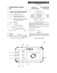
Referring to FIG. 1, Which presents a perspective vieW of one
preferred embodiment of the present invention 100 have three
amount of time and ?nally displaying the same single color
?xed position focus points. As further shoWn in FIG. 1 are a
base unit 1 having mounted therein a On/Reset sWitch 2; a
for a second desired amount of time; a sWitch for activating
and deactivating said sWing training aid; and a sWitch for
selecting a desired non-ball focus point; thereby alloWing the
user to determine if he focused on the selected non-ball focus
point until after impacting the ball and completion of the
sWing.
According to a yet further aspect of the present invention,
there is provided a golf sWing training apparatus teaching
DESCRIPTION OF THE PREFERRED
EMBODIMENTS OF THE INVENTION
20
Mode sWitch 3; a position 1 focus point three color LED
cluster 4; a position 2 focus point three color LED cluster 5;
a position 3 focus point three color LED cluster 6; and a
?exible tubular golf ball tee stem 7.
Referring noW to FIG. 2; there is shoWn a perspective vieW
of one embodiment of the present invention 100; comprising
eye-hand coordination for impacting a golf ball comprising: a
a base unit 1 having mounted therein a On/ Reset sWitch 2; a
golf sWing training aid comprising a base unit having located
Mode sWitch 3; a position 1 focus point three color LED
cluster 4; a position 2 focus point three color LED cluster 5;
a position 3 focus point three color LED cluster 6; a ?exible
tubular golf ball tee stem 7, (said ?exible tubular golf ball tee
stem having a ball mounting end; a tee mounting end; and a
Wall de?ning a bore through the longitudinal axis of said
?exible tubular golf ball tee stem), replaceably mounted per
pendicularly to the top surface of said base unit 1; having an
infrared emitter transmitter 8 and an infrared photo transistor
thereon a substantially cylindrical body and a ball holder
positioned on one end of said substantially cylindrical body;
a ball detecting apparatus in said sWing training aid operable
25
in a con?guration for determining the presence or absence of
a ball on said ball holder; and a parallax correcting position
selectable module comprising three colored indicator lights
operable in a con?guration to display a single color for a
desired amount of time after the ball is impacted off of said
ball holder, then turning off for a desired amount of time and
?nally displaying the same single color for a second desired
amount of time; a sWitch for activating and deactivating said
sWing training aid; and a sWitch for selecting a desired non
ball focus point; thereby alloWing the user to determine if he
30
receiver 9 mounted Within said base unit 1 so as to transmit
and receive an infrared signal through the bore of the tubular
of said ?exible tubular golf ball tee stem 7; and having shoWn
a golf ball 10 mounted upon the ball mounting end of said
35
focused on the selected non-ball focus point until after
impacting the ball and completion of the sWing.
4; focus point position 3 LED cluster 6; Wherein each focus
point position LED cluster has a ?exible black glare reducing
The present invention thus advantageously provides a rug
ged, inexpensive, but highly effective non-ball focus point
golf sWing training aid.
40
FIG. 1 shoWs a perspective vieW of one embodiment of a
of the tubular of said ?exible tubular golf ball tee stem 7; the
complete unit mounted in a golf turf pad 12 designed to
non-ball focus point golf sWing training aid of the present
invention.
FIG. 2 shoWs a perspective schematic vieW of the embodi
50
FIG. 4 shoWs a block diagram of one embodiment of a
non-ball focus point golf sWing training aid of the present
55
rithm used by the micro controller of the non-ball focus point
circuit 16 all electrically connected via appropriate Wiring.
FIG. 6 shoWs a schematic of the main program algorithm
Turning noW to FIG. 5 there is shoWn a block diagram of
60
used by the micro controller of the non-ball focus point golf
sWing training aid of the present invention.
FIG. 8 shoWs a schematic of the mode selection interrupt
focus point golf sWing training aid of the present invention.
the microcontroller procedure used to poWer up the present
invention comprising the steps of starting the procedure 20;
de?ning and initialiZing the program variables 21; declaring
FIG. 7 shoWs a schematic of the ball detection algorithm
handler algorithm used by the micro controller of the non-ball
ter 8 and an infrared photo transistor receiver 9; a battery
compartment 13 mounted Within a base unit 1 for mounting
batteries 14; a microcontroller 15; and a ball sensor receiver
golf sWing training aid of the present invention.
used by the micro controller of the non-ball focus point golf
sWing training aid of the present invention.
receive said base unit 1 therein.
Referring to FIG. 4; there is illustrated a block diagram of
the embodiment of the present invention of FIG. 1 shoWing
one embodiment of the electrical circuitry of the present
invention including the PoWer/Reset sWitch 2; Mode sWitch
3; a position 1 focus point three color LED cluster 4; a posi
tion 2 focus point three color LED cluster 5; a position 3 focus
point three color LED cluster 6; an infrared emitter transmit
1 mounted in a golf turf pad.
invention.
FIG. 5 shoWs a schematic of the poWer up and reset algo
tube 11 mounted over each said focus point position LED
cluster 4 and 6; as Well as shoWing ?exible tubular golf ball
tee stem 7 With infrared emitter transmitter 8 and a infrared
Photo transistor receiver 9 mounted Within said base unit 1 so
as to transmit and receive an infrared signal through the bore
BRIEF DESCRIPTION OF THE DRAWINGS
ment of FIG. 1.
FIG. 3 shoWs a plan front vieW of the embodiment of FIG.
?exible tubular golf ball tee stem 7.
FIG. 3 is a plan vieW through section line A-A of FIG. 2
shoWing a base unit 1 With focus point position 1 LED cluster
microcontroller port and pin assignments 22; all Without a
ball on the tee 23; then the microcontroller measures the
65
current battery voltage 24; to determine if the battery voltage
is <4 VDC; if yes the active position’s red LED ?ashes 25
times to indicate the need to replace the batteries 26; When no
US 7,513,833 B1
5
6
the ball detection algorithm is initiated 27; next the presence
acceptable, beloW 4 volts DC, the red LED of the active focus
point Will ?ash rapidly. After a loW battery condition has been
detected, the training aid of the present invention Will attempt
of a ball on the tee is determined 28; if yes and there is yet no
ball mounted the active position’s blue LED ?ashes 75 times
to indicate that the Tee’s inner stem Wall is dirty and requires
cleaning; if no ball is detected the last active position used is
read from the EEPROM memory 30; all three colored lights
?ash sloWly to indicate the device has been successfully poW
ered up 31; the device microcontroller proceeds to the main
normal operation. The golfer, should hoWever, replace the
loW batteries to ensure proper operation of the training aid of
the present invention.
After the battery check the training aid of the present inven
tion Will next perform a ball detection self check. If the
program 32.
FIG. 6 shoWs a block diagram of the microcontroller main
training aid of the present invention detects an object during
this self check, When there is no ball or other object present on
program comprising the steps of starting the main program
40; initiating the ball detection algorithm 41; determining if a
the tee, the training aid of the present invention Will indicate
this ball detection error by ?ashing the active focus point blue
LED rapidly for an extended period of time. If the training aid
of the present invention fails this self check, clean the sensor
ball is present 42; if no return to step 41 and repeat; if yes has
the system been initialiZed 43; if no then sequence the active
focus point LED cluster to indicate that the device detects the
presence of the ball 44; pause for 4 seconds 45; ?ash the active
focus point red LED to indicate the device is ready to use 46;
and tee stem inner Wall With a cotton sWab or compressed air.
After cleaning the training aid of the present invention, the
golfer selects the Reset/ On sWitch again to restart the training
if yes for step 43 initiate the ball detection algorithm 47; if
step 48 returns a no then proceed to step 47; after step 47 is
completed proceed to step 48 to determine if the ball has come
off the tee; if yes Wait 20 ms 49; then randomly select one of
the 3 LED colors 50; turn the randomly selected LED color of
step 50 on for 35 ms and then turn off 51; Wait 6 seconds 52;
then turn on the randomly selected LED for 4 seconds and
then turn it off 53; return to step 41.
FIG. 7 shoWs a block diagram of the ball detection algo
20
the base of the inner tee stem. If too much dirt or debris lines
the inner tee Wall the training aid of the present invention Will
falsely detect the presence of the ball.
25
rithm comprising the steps of starting the procedure 60; ini
increment the pulse counter by one 67; then check to see if the
pulse loop has been executed 4 times 68; if no return to step 62
and if yes check to see if the pulse counter equals eight 69; if
golfer chooses the position to correct the parallax for the club
30
LED indicating that this focus point has been successfully
selected. The golfer Will select the focus point based on the
35
72; and if yes set the “ball on tee” variable to true 71 and move
to return step 72.
FIG. 8 shoWs a block diagram of the mode selection inter
40
When an interrupt is detected by the microcontroller then read
the active position counter 82; then increment the active po si
45
present invention Will ?ash the active focus point’s red LED
six times indicating that the device has been initialiZed and is
ready for use.
The golfer’s eyes are focused on the activated focus point
50
and not the ball. Preferably, the golfer maintains indirect
visual contact With the ball using peripheral vision.
The golfer’s sWing is initiated.
Almost immediately after the ball has been hit, one of the
three colored LED’ s Will be randomly chosen by the training
sWitch 3; a single focus point three color LED cluster 4
mounted on moveable slide 17, said cluster 4 and slide 17
the three LED cluster is located. The golfer’s eyes Will then
focus on this position point instead of the ball.
NoW the golferplaces a golf ball on the tee. The training aid
of the present invention Will ?ash the active focus point LEDs
in a red, green and blue sequence to indicate that the training
aid of the present invention detects the presence of the golf
After approximately four seconds, during Which the golfer
gets into the desired sWing position, the training aid of the
memory 85; then ?ash the active position’s three colored
LED indicating the neW focus point position has been
selected and the device is poWered up and ready to use 86; and
resume the program Where the interrupt occurred 87.
FIG. 9 shoWs a perspective vieW of another preferred
embodiment of the present invention 100 including a base
unit 1 having mounted therein a On/Reset sWitch 2; a Mode
desired golf instruction philosophy and their current golf
sWing mechanics. The focus point is the place Where one of
ball and that all three LEDs are functional.
tion counter by one 83; noW check to see if there have been
any additional mode sWitch selections Within the last second
84; if yes return to step 82; if no save the neW active position
value into the microcontroller’s non-volatile EEPROM
and sWing position that Will be practiced. The training aid of
the present invention Will illuminate the focus point’s red
no set the “ball on tee” variable to false 70 and move to return
rupt handler comprising the steps of starting the program 80;
The golfer then chooses one of the focus point positions (1,
2, or 3) by pressing the Mode SWitch after the training aid of
the present invention has been successfully poWered up. In
the case of the embodiment of the moveable focus point the
tialiZing the pulse counter to Zero 61; turn on IR emitter (true
state) 62; is the photo transistor in a true state 63; if no skip
step 65; if yes increment the pulse counter by one 64; then
turn off the IR Emitter (false state) 65; determine if the photo
transistor is in a false state 66; if no skip to step 68; if yes
aid of the present invention. The golfer ensures that there is no
ball or other object on the tee before restarting the training aid
of the present invention. The ball detection sensor is located at
55
device microprocessor and ?ashed for a fraction of a second.
moveable Within base unit 1 focus point positioning track 18;
If the golfer has kept his eyes on the focus point, the golfer
and a ?exible tubular golf ball tee stem 7.
Will see the LED ?ash and Will be able to determine the color
In practice; the golfer, before poWering the training aid of
of the randomly ?ashed LED. HoWever, if the golfer has
the present invention on, ensures that there is no ball or other
object on the tee.
moved his eyes or head and thereby lost visual contact With
the selected focus point he Will not be able to identify the
60
Then the training aid of the present invention is turned on
using the ON/Reset sWitch Which Will Wake the training aid of
color ?ashed by the focus point LEDs.
Approximately four seconds after the ball is hit and the
the present invention from the poWered doWned sleep mode it
randomly chosen color LED is ?ashed, the same color LED
normally resides in When not in use.
At poWer up, the training aid of the present invention Will
indicate acceptable battery life by ?ashing the active focus
point LED position’s green LED. If the battery level is not
65
Will be lighted for approximately ?ve seconds. Thus the
golfer has approximately four seconds to identify the ran
domly chosen color ?ashed by the LEDs before the con?r
mation lighting of the same color takes place.
US 7,513,833 B1
8
7
said at least one focus point assembly being positioned
To continue practicing the golfer places another ball on the
tee and the process is repeated from this same point in the
at a desired location aWay from the ball;
thereby alloWing the user to determine if he focused on the
description above.
Another situation that the present invention addresses is the
fact that With different tee heights for positioning the ball for
01
different types of clubs can be an amount of parallax error
introduced into the sight picture of the golfer. For example the
focus point located aWay from the ball until after impact
ing the ball.
2. A golf sWing training aid as claimed in claim 1 Wherein,
there is one focus point assembly positioned at a desired
location behind the substantially cylindrical body capable of
height of the tee and therefore the ball When teed up for a
Wood is different from the height of the ball When using an
iron or putter. This parallax error requires correction to alloW
the golfer to vieW the focus point in-line With the ball and the
mounting a ball thereon.
3. A golf sWing training aid as claimed in claim 1 Wherein,
there is one focus point assembly positioned at a desired
cup for various tee heights. By moving the position of the
location in front of the substantially cylindrical body capable
focus point Which is in front of the ball closer or farther aWay
from the ball on an axis perpendicular to the ?ight line of the
of mounting a ball thereon.
4. A golf sWing training aid as claimed in claim 1 Wherein,
there is more than one focus point assembly positioned at
ball alloWs the golfer to automatically correct for the parallax
error introduced by changing the height of the ball off of the
turf. Applicant has found that a movement along this line
perpendicular to the line of ?ight of the ball of from about 0
desired locations in front of the substantially cylindrical body
inches to about 1.75 inches corrects parallax error resulting
from a ball sitting on the turf to one placed on a tee of up to 20
substantially cylindrical body capable of mounting a ball
about 3 inches in height.
The present invention may be constructed of plastics com
monly used to produce golf tees and the like. Such plastics
thereon.
6. A golf sWing training aid as claimed in claim 1 Wherein,
there are three focus point assemblies positioned at desired
include for example; polypropylene; butylenes and the like;
as Well as plastics used for such items as super balls Which
25
locations in front of, the substantially cylindrical body
capable of mounting a ball thereon.
7. A golf sWing training aid as claimed in claim 1 Wherein,
provide a dense; shock absorbing medium to protect the inter
nal components of the present invention from damage due to
shock.
The training aid of the present invention may be used alone
or preferably it is ?rst mounted under a golf mat that so as to
capable of mounting a ball thereon.
5. A golf sWing training aid as claimed in claim 1 Wherein,
there is one focus point assembly positioned behind, and at
least one focus point assembly positioned in front of, the
there is one focus point assembly positioned directly behind,
and three focus point assemblies positioned at desired loca
30
tions in front of, the substantially cylindrical body capable of
mounting a ball thereon.
more closely imitate actual gol?ng conditions and to protect
the training device from unnecessary physical impact by the
8. A golf swing training aid as claimed in claim 1 Wherein,
golfer’s club. There is no special requirements for a golf mat
for use With the training aid of the present invention other than
it have opening to alloW the golfer to see the focus point
LEDs, access the sWitches, and mounting the tee in the train
said golf sWing training aid is dimensioned to ?t in an appro
priately dimensioned cavity on the underside of a golf mat
such that said at least one focus point assemblies and said
35
substantially cylindrical body capable of mounting a ball
thereon protrude a desired distance above the top surface of
said conventional golf mat.
9. A golf sWing training aid as claimed in claim 1 Wherein,
ing device of the present invention for holding the golf ball.
The presently preferred golf mat is Fiberbuilt golf mat pro
duced by Fiberbuilt Manufacturing Inc. of Calgary, Alberta,
Canada Which has been modi?ed to meet the above require
40
ments.
Although the preferred embodiments of the present inven
tion have been disclosed; various changes and modi?cations
may be made Without departing from the scope of the inven
tion as set forth in the appended claims.
said golf ball detecting apparatus comprises an ambient light
photo detector.
45
color light emitting diodes (LED).
1. A golf training apparatus for teaching eye-hand coordi
12.A golf sWing training aid as claimed in claim 1 Wherein,
said three colored indicator lights are a single tricolor light
50
bination;
emitting diode (LED) capable of emitting three separate col
ors of light.
a substantially boxed shape training apparatus having a top
13. A golf training apparatus for teaching eye-hand coor
dination for impacting a golf ball using a golf club compris
surface, bottom surface, and at least one side surface;
a substantially cylindrical body capable of mounting a ball
on one end, removably mounted to said top surface of
11 . A golf sWing training aid as claimed in claim 1 Wherein,
said three colored indicator lights are three separate single
What is claimed is:
nation for impacting a golf ball using a golf club comprising:
a golf sWing training aid comprising in cooperative com
said golf ball detecting apparatus comprises an infrared emit
ter and corresponding infrared detector.
10.A golf sWing training aid as claimed in claim 1 Wherein,
ing:
55
said training apparatus;
a golf ball detecting apparatus in said golf training appa
a golf sWing training aid comprising in cooperative com
bination;
a substantially boxed shape training apparatus having a top
ratus operable in a con?guration for determining the
surface, bottom surface, and at least one side surface;
presence or absence of a ball on said substantially cylin
a substantially cylindrical body capable of mounting a ball
drical body ball mounting end; and
60
single color for a desired amount of time after the ball is
impacted off of said substantially cylindrical body, then
turning off said single color indicator light for a desired
amount of time and ?nally displaying the same single
color indicator light for a second desired amount of time,
on one end, removably mounted to said top surface of
said training apparatus;
a golf ball detecting apparatus in said golf training appa
ratus operable in a con?guration for determining the
at least one focus point assembly having three colored
indicator lights operable in a con?guration to display a
presence or absence of a ball on said substantially cylin
65
drical body ball mounting end; and
a single focus point assembly moveable along a predeter
mined track in front of the substantially cylindrical body
US 7,513,833 B1
10
15. A golf sWing training aid as claimed in claim 13
having three colored indicator lights operable in a con
?guration to display a single color for a desired amount
of time after the ball is impacted off of said substantially
Wherein, said golf ball detecting apparatus comprises an
infrared emitter and corresponding infrared detector.
16. A golf sWing training aid as claimed in claim 13
cylindrical body, then turning off said single color indi
cator light for a desired amount of time and ?nally dis
playing the same single color indicator light for a second
desired amount of time, said at least one focus point
assembly being positioned at a desired location aWay
Wherein, said golf ball detecting apparatus comprises an
ambient light photo detector.
17. A golf sWing training aid as claimed in claim 13
Wherein, said three colored indicator lights are three separate
from the ball;
thereby alloWing the user to correct for parallax error for
the desired tee height and to determine if he focused on
the focus point located aWay from the ball until after
single color light emitting diodes (LED).
18. A golf sWing training aid as claimed in claim 13
Wherein, said three colored indicator lights are a single tri
impacting the ball.
14. A golf sWing training aid as claimed in claim 13
Wherein, said golf sWing training aid is dimensioned to ?t in
an appropriately dimensioned cavity on the underside of a
conventional golf mat.
15
color light emitting diode (LED) capable of emitting three
separate colors of light.