1
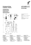
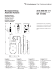
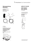
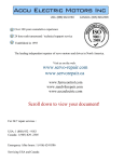
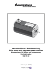
Montageanleitung
Automatic-Antenne
AUTA 6000 KE 14
Bestell-Nr. / Ord. code / Réf. de cde.
921 386-001
Installation instructions
Automatic Antenna
Instructions de montage
Antenne automatique
Automatic-Antenne
Universaltyp für Heckeinbau
Anschlussleitungen ca. 4,85 m lang, mit
zwei Antennenköpfen ➀ verstellbar von 0...20° und
➁ mit ca. 34° Neigung.
➀
0...20°
➁
Automatic Car Antenna
Universal type for rear mounting
Connection cables approx. 4.85 m long, with two
antenna heads ➀ adjustable from 0...20° inclination
and ➁ of approx. 34 ° inclination.
34°
sw
Antenne automatique
Modèle universel pour montage à l'arrière
Conduites de raccordement env. 4,85 m de longueur, avec deux têtes d'antenne ➀ réglable de
0...20° d'inclinaison et ➁ avec une inclinaison
d'env. 34°.
ws
rt
Dieses Produkt ist nach seiner Verwendung entsprechend den aktuellen Entsorgungsvorschriften
Ihres Landkreises / Landes / Staates als Elektronikschrott einer geordneten Entsorgung zuzuführen.
Technische Änderungen vorbehalten.
After its use, this product has to be processed
as electronique scrap to a proper disposal
according to the prevailing waste disposal regulations of your community / district / country / state.
ws
rt
Right of modification reserved.
Ce produit doit être éliminé en tant que déchet
électronique conformément au réglement actuel
sur l'élimination des déchets de votre département / région / pays.
Sous réserve de modifications techniques.
+12V +12V 150 Betriebsspannung
9 ... 16 VOperating voltage
9 ... 16 VDC
Tension de service
9 ... 16 V
Leitungsfarben
Leads colours
Couleurs des conduites
rt: rot/red/rouge
sw: schwarz/black/noir
ws: weiß/white/blanc
D
Antenna installation
Installation de l'antenne
Die Antenne wird nur für Fahrzeuge
mit 12 V Batteriespannung geliefert,
wobei Minus am Chassis liegen muß.
The antenna is supplied only for
cars with 12 V battery operating
voltage with minus being connected
to the chassis.
L'antenne n'est disponible que
pour des véhicules avec une tension
de batterie de 12 V, supposé que le
pôle négatif se trouve au châssis.
The antenna is mainly appointed for
installation in the rear from inside
the boot.
L'antenne est surtout destinée à
être installée à l'arrière du véhicule
en partant du coffre.
The installation place is normally
behind the rear window; there must
be sufficient space in the boot for the
drive case (behind the wheel box).
En règle générale, I'endroit de
montage se trouve derrière la lunette
arrière pourvu qu'il y ait un espace
suffisant pour le boîtier moteur
dans le coffre (derrière le passage
de roue).
Der Einbauort liegt hierbei in der
Regel hinter der Heckscheibe,
wobei für das Antriebsgehäuse im
Kofferraum genügend freier Raum
(hinter dem Radlauf) vorhanden
sein muß.
Für einige Fahrzeugtypen finden Sie
den Einbauvorschlag in der beiliegenden Übersicht bzw. in unserer
Druckschrift "Welche Antenne für
welchen Wagen?"
A115
Zur Sicherheit die Verbindung zum
Batterie-Minuspol abklemmen;
dazu Anweisung des Herstellers
beachten!
?
F
Antenneneinbau
Die Antenne ist vorwiegend zum
Einbau am Fahrzeugheck vom Kofferraum aus bestimmt.
Ø 22...23 mm
GB
For several car types you will find
the installation suggestion in the
summary being enclosed or in our
publication "Which antenna for
which car?"
Disconnect battery minus for security, according to the instructions of
the manufacturer of the radio!
Pour quelques types de véhicule
vous trouverez notre conseil de
montage dans le tableau ci-joint ou
bien dans notre imprimé "Quelle
antenne pour quelle voiture?" .
Pour des raisons de sécurité,
débrancher le pôle négatif de la
batterie, selon les données du constructeur de la radio.
An der Einbaustelle ein Loch entsprechend der Angabe zum verwendeten Antennenkopf bohren.
Drill a hole at the installation place
according the used antenna head.
A l'endroit de montage perçer un
trou selon les données qui se
réfèrent à la tête d'antenne utilisée.
Der Antenne liegen 2 Antennenköpfe bei, ➀ und ➁. Weitere
Antennenköpfe bis 61° Karosserieneigung sind als zusätzliche Einbauteile erhältlich, siehe hierzu beiliegende Übersicht.
Two antenna heads ➀ and ➁. are
supplied with the antenna. Additional antenna heads for up to 61° car
body inclination are available as
mounting parts, see the enclosed
summary.
Die Antenne zum Einbau vorbereiten.
Prepare the antenna for installation.
Deux têtes d'antenne ➀ et ➁ se
trouvent jointes à l'antenne.
Des autres têtes d'antenne pour
une inclinaison de carrosserie jusqu'à 61° sont disponibles comme
pièces supplémentaires nécessaires pour le montage, voir le tableau
ci-joint.
Prepare the fixing parts enclosed in
a separate plastic bag.
Préparer l'antenne pour le montage.
Attach the lower parts as shown in
the equivalent figure.
Préparer les pièces de fixation
emballées séparément.
For antenna heads MCA... don't
use spacer 721 957-001.
Mettre les pièces inférieures selon
la figure correspondante.
?
➀
;;;
;;
entgraten
remove the burr
enlever la bavure
822 649-002
ø 22 mm
;
;;
;;
721 957-001
0...20°
Die separat verpackten Befestigungsteile bereit legen.
Die unteren Teile gemäß zugehöriger Abbildung aufsetzen.
A116
Bei den Antennenköpfen Typ
MCA... entfällt der Distanzring
(721 957-001).
2
Pour des têtes d'antenne type
MCA... n'utilisez pas l'anneau
entretoise 721 957-001.
;
;; ;
m
➁
821 964-003
ø
23
m
;;
;
721 957-001
Fasten the HF connection cable to
the antenna.
Visser à fond le câble de raccordement H. F. à la rallonge de l'antenne.
Die Antenne von unten her in die
Bohrung einsetzen; dabei muß sich
der jeweilige Messerring durch den
Schutzring in der Bohrung zentrieren.
Der Messerring bewirkt zusammen
mit dem fettgetränkten Schutzring
eine gute und dauerhafte Masseverbindung der Antenne mit der
Karosserie, wie sie für die Abschirmung von Antenne und Kabel
unbedingt erforderlich ist.
Insert the antenna from below into
the hole; the blade ring must be
centered in the hole by the foam
ring. The blade ring provides,
together with the greased foam
ring, a good and durable connection between the antenna and the
car body, as required for shielding
of antenna and cable.
Placer l'antenne dans le perçage
de dessous; chaque anneau à couteau doit se mettre au centre de la
perçage à travers de l'anneau protecteur. Avec l'anneau protecteur
graisseux l'anneau à couteau produit une connexion à la masse de
l'antenne avec la carrosserie qui est
bonne et stable, comme il est
absolument nécessaire pour protéger antenne et câble contre des
parasites.
Attach the upper fixing parts and
slightly tighten the nut.
Die oberen Befestigungsteile aufsetzen und die Mutter leicht anziehen.
Mettre les pièces de fixation
supérieures et serrer légèrement
l'écrou.
A117
34°
Das Antennenkabel am Antennenstutzen fest anschrauben.
Die Stutzenstellung kann beliebig
gewählt werden.
Dazu die Torx-Schraube A lösen, das
Schutzrohr gemäß der gewünschten
Stellung des Antennekopfes drehen
und abschliessend wieder anziehen.
The position of the antenna
connection socket can be optionally
selected.
To do so, loosen the Torx-screw A,
from the portective tube to the
desired position of the antenna
head and then tighten the screw
again.
La position de la rallonge peut être
choisie selon vos besoins.
A cet effet desserrer la vis Torx A,
faire tourner le tube protecteur
selon la position désirée de la tête
d'antenne et alors visser à fond.
A118/2
A
A119/6
ws
rt
sw
Die Antenne zur Festlegung der
Teleskopneigung ausfahren.
For setting the telescope inclination
extend the antenna.
Faire sortir l'antenne afin de déterminer l'inclinaison du télescope.
Anschlussleitung einstecken.
Plug-in the connection cable.
Zum Ausfahren - die schwarze
Leitung (sw) an den Minuspol - die
rote Leitung (rt) an den Pluspol
und danach zum Ausfahren die
weiße Leitung (ws) an den Pluspol
der Batterie anschliessen; zum Einfahren weiße Leitung wieder
abnehmen.
For extending - connect the
black cable (sw) to minus - the
red cable (rt) to plus - finally the
white cable (ws) also to plus; for
retracting only disconnect the white
cable.
Enficher les conduites de raccordement.
HF- und Motoranschlusskabel
durch den Innenraum (meist entlang der seitlichen Trittleiste) nach
vorne verlegen.
Pass the HF cable and the motor
cable inside the car to the front
(usually along the threshold).
Pour sortir - raccorder la conduite
noire (sw) au pôle négatif - la conduite rouge (rt) au pôle positif et
alors pour sortir raccorder la conduite blanche (ws) au pôle positif
de la batterie; pour faire rentrer,
débrancher la conduite blanche.
Poser le câble H. F. et le câble de
raccordement du moteur à travers
de l'intérieur de la voiture vers
l'avant (normalement le long du
marchepied latéral).
3
Der obere Knopf am ausgefahrenen
Teleskop muß mindestens 100 mm
innerhalb des Fahrzeugumrisses
liegen.
The top of the fully extended telescope must be at a distance of 100
mm minimum from the car outline.
Le bouton supérieur du télescope
sorti doit se trouver au moins à 100
mm à l'intérieur de la silhouette du
véhicule.
Die notwendige Halterlänge und stellung entsprechend festlegen.
Determine the length and the position of the bracket as required.
Déterminer la longueur et la position
requise du support.
Halter richten.
Adjust the bracket.
Ajuster le support.
An der Antenne kann der Halter in
verschiedenen Varianten angebracht
werden.
The bracket can be applied to the
antenna in different positions.
Pour la fixation du support à l'antenne il y a plusières variantes.
Zum Abschluß den Halter mit den
Blechschrauben befestigen und am
Antriebsgehäuse arretieren (siehe
Pfeil).
Finally fix the bracket with tin screws
to the drive case (see arrow).
Pour finir arrêter le support avec
des vis en tôle au boîtier moteur
(voir flèche).
A120
≥100 mm
A121
;;;
;
;
;
x
A123
A122
x
1. Variante
A124
2. Variante
Ø 4,8 mm
;;;;;
;
;
Die Sechskantmutter am Antennenkopf und die Schrauben am
Halter fest anziehen.
Tighten the hex nut on the antenna
head and the screws at the
bracket.
Visser à fond l'écrou hexagonal à la
tête d'antenne et les vis au support.
arretieren
fix
arrêter
4
rt
sw
5A
Wagensicherungen
Car fuses
Fusibles de bord
K 30
ø 6,5
+
–
Batterie
12 V
Die Leitungen wie folgt anschließen:
(Siehe hierzu auch das Schaltschema)
Connect the leads as follows (see
also the wiring diagram):
Die schwarze Leitung (sw) an
Minuspol (Fahrzeugmasse) anschließen; dazu den beiliegenden
Kabelschuh Ø 6,5 aufquetschen.
Connect the black lead (sw)
to minus (car chassis); for that purpose crimp the cable 6.5 dia. to the
lead (both are enclosed).
Brancher la conduite noire (sw)
au pôle négatif (masse du véhicule);
pour cela empreindre la cosse de
câble ci-jointe de Ø 6,5.
Connect the red lead (rt) with
cable fuse (8A) to a cable being
directly connected to battery plus,
e.g. to clamp 30 on the car fuses
or to the light switch.
Brancher la conduite rouge (rt)
avec fusible de câble (8 A) à une
conduite qui est directement raccordée au pôle positif de la batterie, p. ex. à la borne 30 aux fusibles
de bord ou au commutateur
d'éclairage.
Pass the white control lead (ws)
and the antenna cable to the installation place of the car radio. lf a suitable blade contact for automatic
antennas is provided at the radio,
crimp the flat receptable 2.8-1 to
the cable end.
Poser la conduite de commande
blanche (ws) et le câble d'antenne
jusqu'à l'endroit de montage de
l'autoradio. Si l'autoradio est pourvue
d'une connexion pour une antenne
automatique, empreindre la douille
à fiche plate 2,8-1 ci-jointe.
If connected properly, the antenna
extends when switching on the
radio and retracts when switching
off.
Si l'antenne est correctement raccordée, elle sortira quand l'autoradio
est mise en marche, et elle rentrera
quand la radio est arrêtée.
On first operation, the antenna probably does not extend before switching on and off the radio again.
Lors du premier service de la radio
il est possible que l'antenne sortira
seulement, si l'autoradio est brièvement arrêtée et ensuite mise en
marche de nouveau.
A126
Die rote Leitung (rt) mit Kabelsicherung (8 A) an einer direkt zum
Batterie-Pluspol geschalteten Leitung, z. B. an Klemme 30 an den
Wagensicherungen oder am Lichtschalter, aufstecken.
Brancher les conduites comme suit
(voir aussi le schéma de câblage):
+12V
ws
Die weiße Steuerleitung (ws) und
das Antennenkabel zum AutoradioEinbauort verlegen. Sofern am
Autoradio ein entsprechender
Anschlusskontakt für AutomaticAntennen vorhanden ist, die beiliegende Flachsteckhülse 2,8-1 aufquetschen.
Bei richtigem Anschluss fährt die
Antenne aus, wenn das Autoradio
eingeschaltet - wieder ein, wenn
das Autoradio ausgeschaltet wird.
Beim erstmaligen Betrieb kann es
vorkommen, daß die Antenne erst
ausfährt, wenn das Autoradio
nochmals kurz aus- und wieder
eingeschaltet wird.
Dies kann auch nach dem Wiederanschluss der abgeklemmten Batterie erforderlich sein (Aktivierung
der elektronischen Steuerung).
The circuit is designed pole-confusing-proof, but operates only if properly connected.
Die Schaltung ist verpolungssicher,
funktioniert jedoch nur bei richtigem
Anschluss.
The plug at the HF cable can be
used staight or, if required, as an
angled plug. Please bend the plug
only by hand.
Der Stecker am HF-Kabel kann je
nach Bedarf gerade oder als Winkelstecker verwendet werden. Das
Abbiegen über den Führungsrücken
bitte nur von Hand durchführen.
5
This may be necessary, too, after
reconnection of the battery (to
activate the electronic control circuit).
Cela peut être aussi nécessaire
après le raccordement de la batterie
débranchée (activation du circuit de
commande électronique).
La commutation est protégée contre
une polarisation incorrecte, et elle
ne marche qu'après un branchement correct.
Le connecteur au câble H. F. peut
être utilisé, si besoin est, droitement
ou comme fiche coudée. Ne la tordre
que manuellement par dessus le
tube conducteur.
Schaltschema
Wiring diagram
Schéma de câblage
Antenne
Radio
+12V
ws
12 V
rt
sw
+ 12 V
150 K 30
–
+
12 V
Batterie
Gebrauchs- und
Pflegeanleitung
AUTA 6000 ...
Bitte die beigefügte Gebrauchsund Pflegeanleitung mit Garantiekarte und den beiden Autoantennen-Pflegetüchlein (AUTA
135) dem Kunden aushändigen.
Please hand over to the customer the enclosed instructions
for use and maintenance with
guarantee certificate as well as
the two car antenna tissues
(AUTA 135).
Veuillez transmettre au client le
mode d'emploi et d'entretien cijoint avec le bulletin de garantie
et les deux essuies-antenne
(AUTA 135).
Ersatzteile bitte unter den angegebenen Nummern bestellen.
Please state order codes when
ordering spare parts.
Veuillez commander les pièces
détachées sous les numéros indiqués.
Automatic-Antenne:
Radio einschalten - Antenne fährt
aus.
Radio ausschalten - Antenne fährt
ein.
Automatic Antenna:
Switch radio on - antenna will
extend.
Switch radio off - antenna will
retract.
Antenne automatique:
Mettre en marche la radio l'antenne sort.
Arrêter la radio - l'antenne rentre.
Einfacher Teleskopwechsel ohne
Ausbau der Antenne möglich.
Easy telescope exchange possible
without antenna removal.
Possibilité d'échanger simplement
le télescope sans démonter l'antenne.
Die beschriebenen Leistungsmerkmale sind nur dann verbindlich,
wenn sie bei Vertragsabschluss ausdrücklich vereinbart wurden. Diese
Druckschrift wurde von Hirschmann
Car Communication GmbH auf Übereinstimmung mit den beschriebenen
Antennen und Antennenzubehör
(Kabel, Stecker etc.) geprüft. Dennoch können Abweichungen hinsichtlich der Richtigkeit oder
Genauigkeit nicht ausgeschlossen
werden, sodass Hirschmann für die
vollständige Übereinstimmung
keine Gewähr übernimmt.
Hirschmann behält sich das Recht
vor, den Inhalt dieser Druckschrift
ohne Ankündigung zu ändern.
The performance features described here are binding only if they
have been expressly guaranteed in
the contract. This publication has
been created by Hirschmann Car
Communication GmbH according to
the best of our knowledge.
Hirschmann reserves the right to
change the contents of this manual
without prior notice.
Hirschmann can give no guarantee
in respect of the correctness or
accuracy of the details in this publication.
La société Hirschmann Car Communication GmbH ne se porte garante de
la véracité des informations techniques que si elles ont été spécifiées
de manière expresse à la signature
du contrat.
Le contenu de ce document a été
minutieusement contrôlé afin de
s’assurer qu’il corresponde bien aux
antennes et accessoires (câbles,
connecteurs) décrits. Toutefois,
Hirschmann ne peut en aucun cas
être tenu responsable de l’exactitude
de ces informations.
Hirschmann se réserve le droit de
modifier sans préavis le contenu de
ce document.
Für den Kunden bestimmt
Instructions for use and
maintenance
Intended to the customer
Mode d'emploi et
d'entretien
Destiné au client
Hirschmann Car Communication GmbH
Stuttgarter Strasse 45 - 51
D - 72654 Neckartenzlingen
Tel (07127) 14-1873
Fax (07127) 14-1428
024 888-001-07-0905-N
Printed in Europe . Imprimé en Europe