Download BTS-1 Instructions
Transcript
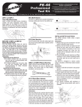
BTS-1 Bottom Bracket
Tapping and Facing Set
Park Tool Co. 5115 Hadley Ave. N., St. Paul, MN 55128 (USA) www.parktool.com
The ParkTool BTS-1 is a precision tool system that provides a piloted means for tapping
the threads of a frame’s bottom bracket shell and for cleaning up the two faces of the
shell for proper bottom bracket fit and performance.
INSTRUCTIONS
Always wear safety glasses when using the BTS-1 or any cutting tool.
Mount the frame to be tapped in a ParkTool repair stand.
Determine the appropriate taps for the bottom bracket thread standard of the frame.
1.370” x 24TPI English taps are supplied with the BTS-1. These are marked in the flutes
with RH and LH, which designates the direction of the threading, NOT the side of the
frame in which the tap is used. The tap marked LH is used in the right or drive side (the
side with the chainrings). The tap marked RH is used in the left or non-drive side (Figure
1). Optional 36mm x 24TPI Italian taps are available as accessories. Both the drive side
and non-drive side of a frame using the Italian thread standard use a right hand thread.
Two #693 Italian threaded taps are required for the job.
Install the taps onto the handle weldments by slipping them over the spring retainers
and onto the driver pins. The spring retainers hold the taps onto the handle weldments,
yet allow the handles to be removed after the taps are in the frame for installation of the
facing cutter. Use care to be sure the handles are not dropped or swung sharply, as the
taps could fall off and be damaged. The spring retainers (Part #674) are inexpensive wear
parts. If tap retention becomes too loose, they should be replaced.
Liberally apply CF-2 ParkTool Cutting Fluid to the frame threads and to each tap. Simultaneously position both taps into the appropriate sides of the frame. Using handles,
carefully turn each tap in the appropriate direction to engage the first few threads in
the frame (Figure2). Once engaged in the threads, turn each tap until resistance is felt.
From this point on, turn each tap no more than one-half turn into the resistance, then
back up one-quarter turn to break and clear the metal chips formed during the tapping
process. Turn tap slowly to insure a clean thread, taking four seconds to complete each
half revolution. Alternate turning each tap. Apply additional cutting fluid every full rotation of the tap. If the frame needs to be faced, continue tapping until both taps are below
the face of the frame’s bottom bracket shell (Figure 3).
With the taps in the frame, pull on either handle to remove it from the tap. Install facing
cutter onto handle’s driver pins. Reinstall the handle into the tap. The taps in the frame
now serve as guides for the facing cutter.
Apply cutting fluid to the facing cutter. Turn handle and facing cutter in a clockwise direction while applying hand pressure (Figure 4). Remove only enough material to make a
clean cut 360 degrees around the face of the bottom bracket shell.
When facing of one side is complete, remove both handles and then switch each to the
opposite side. Turn handle and facing cutter in a clockwise direction to face shell (Figure
5). With some frame materials, a slight “chatter” can result on the faced surface. This is
cosmetic only and can often be minimized by adjusting the amount of hand pressure.
Remove the handle holding the facing cutter from the frame. Remove the facing cutter
and reinstall handle into the tap. Simultaneously turn each handle and tap in the appropriate direction to remove from frame. Unthread the taps simultaneously. Do not remove either tap until both are fully disengaged from the threads of the frame (Figure 6).
Rotate frame so bottom bracket shell is down to allow fluid to drain. Remove chips with
a rag, then clean shell with a brush.
NOTES
The BTS-1 is a precision tool and should be used and stored with extreme care. Components should be cleaned after each use and wiped with an oily cloth or rust inhibitor
before storage. Store in a safe place, such as the original carton.
Metal cutting tools by their nature must be very hard, and the teeth are in fact fragile.
Even when care is taken to follow correct procedures, local areas of hardness from welding or other anomalies can damage the taps and facer. Like all cutting tools, the BTS-1’s
taps and facer will require periodic sharpening.
If permanent tap installation is desired, the outermost spring retainers on each handle
may be replaced with the included snap rings (part #675). If the snap rings are used, the
handles cannot be removed from the taps while they are in the frame and the BTS-1
cannot be used to face the bottom bracket shell.
BTS-1TRETLAGERGEWINDESCHNEIDER-SET
Mit diesem Werkzeug-Set werden Gewindeschneid- und Planfräsarbeiten beiTretlagerhülsen
an praktisch allen Fahrradrahmen präzise und schnell durchgeführt, so dass die optimale Passung für Innenlager gewährleistet ist.
ANLEITUNG Tragen Sie immer eine Schutzbrille bei der Benutzung des BTS-1 oder anderer
Schneidwerkzeuge.
Setzen Sie den zu bearbeitenden Fahrradrahmen in einen Montageständer.
Ermitteln Sie die für den Rahmen passenden Schneideisen. 1,37“ x 24TPI BSA Schneideisen
sind bereits im Lieferumfang des BTS-1 enthalten. Diese sind mit der die Gewinderichtung
angebenden Markierungen RH (right-hand, Rechtsgewinde) bzw. LH (left-hand, Linksgewinde)
versehen. Die Markierungen geben NICHT die betroffenen Rahmenseiten wieder. Das mit
LH gekennzeichnete Schneideisen wird für die in Fahrtrichtung rechte Rahmenseite (auf der
die Kette verläuft) verwendet. Das mit RH gekennzeichnete Schneideisen wird auf der linken,
kettenabgewandten Rahmenseite benutzt (Abb. 1). Schneideisen für Italienisches Gewinde
36 mm x 24TPI sind als Zubehör lieferbar. Beim Italienischen Gewindetyp verfügen beide
Rahmenseiten über ein Rechtsgewinde. Es werden dafür zwei Schneideisen #693 Italienisch
benötigt.
Installieren Sie die Schneideisen auf dem Werkzeug, indem Sie diese über die Federarretierungen in die Fixiernuten schieben. Die Federarretierung sichert das Schneideisen auf dem
Werkzeugschaft und ermöglicht derenTrennung, sobald die Scheideisen im Rahmen sitzen
und der Planfräser eingesetzt werden soll. Werfen oder schleudern Sie die beiden Schneidwerkzeuge nicht, da sonst die Schneideisen abfallen und beschädigt werden können. Die
Federarretierungen (#674) sind kostengünstige Verschleißteile. Bei nachlassender Federspannung sollten sie ausgetauscht werden.
Tragen Sie großzügig CF-2 Schneidöl auf Rahmengewinde und Schneideisen auf. Positionieren
Sie beide Schneideisen gleichzeitig und seitenrichtig in derTretlagerhülse und drehen Sie sie
vorsichtig vorn in die Gewinde ein. Sobald die Schneideisen gefasst haben, drehen Sie weiter, bis
Widerstand spürbar wird. Jetzt drehen Sie die Schneidwerkzeuge abwechselnd jeweils um maximal eine halbe Umdrehung hinein und eine viertel Umdrehung zurück, damit die entstehenden
Späne entfernt werden. Drehen Sie beide Schneidwerkzeuge abwechselnd und langsam (ca.
vier Sekunden pro halbe Umdrehung), damit das Gewinde sauber geschnitten wird.Tragen Sie
nach jeder vollen Umdrehung zusätzliches Schneidöl auf. Wenn dieTretlagerhülse anschließend
plangefräst werden soll, drehen Sie beide Schneideisen soweit hinein, dass sich ihre Oberseiten
unterhalb der Außenkanten derTretlagerhülse befinden (Abb. 3).
Sobald beide Schneideisen im Rahmen sitzen, ziehen Sie von einem das Schneidwerkzeug ab.
Installieren Sie den Planfräser auf den Fixiernuten des Werkzeugschafts. Kombinieren Sie das
Werkzeug wieder mit dem Schneideisen. Die im Rahmen befindlichen Schneideisen dienen
jetzt als Führung für den Planfräser.
Geben Sie Schneidöl auf den Planfräser. Drehen Sie das Werkzeug mit dem Planfräser im
Uhrzeigersinn und üben Sie dabei mit den Händen Druck aus (Abb. 4). Fräsen Sie nur soviel
Material ab, bis eine rundum glatte Oberfläche auf der Hülsenkante entstanden ist.
Nach dem Fräsen der einen Seite entfernen Sie beide Schneidwerkzeuge, setzen Sie sie umgekehrt wieder ein und wiederholen Sie den Fräsvorgang im Uhrzeigersinn (Abb. 5). Gelegentlich wird ein leichtes „Rattern“ auf der Oberfläche festgestellt. Das ist nur kosmetisch und kann
meistens durch Veränderung von Anpressdruck und Drehgeschwindigkeit minimiert werden.
Nehmen Sie das Werkzeug mit dem Planfräser aus dem Rahmen. Entfernen Sie den Planfräser
und setzen Sie das Werkzeug anschließend wieder auf das Scheideisen. Drehen Sie beide Schneideisen gleichzeitig aus derTretlagerhülse heraus. Entfernen Sie grundsätzlich Schneideisen erst
dann vom Werkzeug, wenn sich keins mehr davon im Rahmen befindet (Abb. 6).
Drehen Sie den Rahmen so, dass verbliebene Flüssigkeit ablaufen kann. Entfernen Sie restliche
Späne mit einem Lappen und reinigen Sie dieTretlagerhülse anschließend mit einer Bürste.
HINWEISE: Das BTS-1 ist ein Präzisionswerkzeug und sollte mit großer Sorgfalt eingesetzt und
gelagert werden. Die einzelnen Komponenten sollten nach jeder Benutzung gereinigt und mit
einem öligen Lappen abgewischt werden. Lagern Sie die Fräseisen und Führungen an einem
sicheren Ort, wie dem Originalkarton.
Metallschneidewerkzeug muss typbedingt sehr hart sein und die Schneidflächen sind wirklich
empfindlich. Selbst bei sorgfältigster Bedienung können Schneid- und Fräseisen durch Schweißnähte oder andere Materialanomalien beschädigt werden. Wie bei allen Schneidwerkzeugen müssen auch die Schneid- und Fräseisen des BTS-1 gelegentlich nachgeschärft werden.
Zur permanenten Installation von Schneideisen wird die äußere Federarretierung des
Schneidwerkzeugs durch die beiliegenden Sprengringe (#675) ersetzt. In diesem Fall kann
das Schneidwerkzeug nicht vom im Rahmen befindlichen Schneideisen getrennt und zum
Planfräsen verwendet werden.
BTS-1 KIT DETARAUDAGE ET DE SURFAÇAGE
DE BOITIER DE PEDALIER
Le BTS-1 est un outil de précision qui permet un alignement des filetages du boitier de
pédalier ainsi que le surfaçage des bords de cadre pour un ajustement parfait et de meilleurs performances.
Mode d’emploi: Toujours porter des lunettes de protection lors de l’utilisation du BTS-1
ou tout autre outil de coupe.
Fixer le cadre à tarauder sur un pied de réparation ParkTool.
Déterminer les tarauds adéquats pour le taraudage de votre boitier de pédalier. Des
tarauds 1.370’’ x 24TPI Anglais sont fournis avec le BTS-1. Ces tarauds sont marqués RH
ou LH, ce qui indique la direction du pas et NON le coté du cadre sur lequel ils doivent
être utilisés. Le taraud marqué LH est utilisé du coté droit (le coté avec les plateaux et la
chaine). Le taraud marqué RH est utilisé du coté gauche (Fig.1). Des tarauds optionnels
36mm x 24TPI en pas italien sont disponibles. Les deux cotés d’un cadre italien utilisent
un pas vers la droite et donc des tarauds identiques. Deux tarauds sont cependant requis
pour ce travail.
Placer les tarauds sur la poignée en les faisant glisser par-dessus les ressorts de rétention
et en les enclenchant sur les plots. Les ressorts de rétention permettent de garder les
tarauds en place sur la poignée, tout en permettant de retirer celle-ci lorsque les tarauds
sont dans le cadre, pour installer l’outil de surfaçage. Manipuler les poignées avec
précaution, en évitant de les agiter violement, car un des tarauds pourrait se décrocher
et s’abimer en tombant. Les ressorts de rétention (pièce #674) sont des pièces d’usure à
très faible valeur. Si les ressorts deviennent trop souples, ils devraient être remplacés.
Enduire généreusement le pas du boitier de pédalier ainsi que les deux tarauds avec de
l’huile de coupe ParkTool CF-2. Placer simultanément les deux tarauds de chaque coté du
cadre. En utilisant les poignées, tourner doucement chaque taraud dans la direction appropriée afin d’enclencher les premiers filets du taraud dans le cadre (Fig.2) Une fois les
filets enclenchés, tourner chaque taraud jusqu’à rencontrer une résistance. A partir de ce
point, ne pas tourner les poignées plus d’un demi-tour à la fois en prenant ensuite soin
de revenir un quart de tour en arrière afin de casser et évacuer les copaux de métal formés lors du taraudage. Afin de garantir une coupe nette, tourner le taraud lentement de
façon à mettre 4 secondes par demi-tour. Appliquer de l’huile de coupe sur les tarauds à
chaque tour complet. Si le cadre a besoin d’être surfacé, continuer à tourner les tarauds
jusqu’à ce qu’ils soient rentrés entièrement dans le cadre. (Fig.3)
Une fois les tarauds dans le cadre, retirer les poignées en tirant de chaque coté. Installer
l’outil de surfaçage sur la poignée en l’enclenchant sur les plots. Replacer ensuite les
poignées dans les tarauds restés dans le cadre. Les tarauds servent maintenant de guide
pour l’outil de surfaçage.
Appliquer de l’huile de coupe sur l’outil de surfaçage.Tourner la poignée et l’outil de
surfaçage dans le sens des aiguilles d’une montre en appliquant une pression (Fig.4).
Retirer seulement assez de matière pour obtenir une coupe nette à 360° autour du boitier
de pédalier.
Lorsque le surfaçage du premier coté est terminé, retirer les deux poignées et les
intervertir.Tourner ensuite la poignée avec l’outil de surfaçage dans le sens des aiguilles
d’une montre (Fig.5). Avec certains matériaux de cadres, un léger bruit peut être émis
lors du surfaçage. Ceci peut être minimisé en ajustant la pression exercée sur la poignée.
Retirer ensuite la poignée supportant l’outil de surfaçage. Démonter celui-ci et réinstaller
la poignée dans le taraud.Tourner simultanément les deux poignées dans la direction
adéquate pour retirer les tarauds du cadre. Ne pas retirer un des deux tarauds avant
qu’ils soient tous les deux complètement sortis du cadre (Fig.6).
Pivoter le cadre de façon à ce que le boitier de pédalier soit orienté vers le bas pour permettre l’évacuation de l’huile. Nettoyer l’intérieur du boitier avec un chiffon pour enlever
les copeaux, puis avec une brosse.
BTS-1 MANERAL PARA ROSCARY FRESARTAZA DE CENTRO
El BTS-1 de ParkTool es una herramienta con sistema guía espiga de presicion para
roscar las cuerdas de la caja de centro, limpiándola por ambos lados y preparándola para
el montaje de la taza de centro correctamente.
INSTRUCCIONES Siempre utilice lentes de proteccion para los ojos cuando use el BTS1 o cualquier otra herramienta de corte.
Monte el cuadro en un soporte de reparación ParkTool
Seleccione el machuelo apropiado para la cuerda de la caja de centro del cuadro. Un par
de machuelos de rosca inglesa 1.37”x24TPI viene con el BTS-1. Estos vienen marcados
con RH (Rosca derecha) y LH (Rosca Izquierda), lo que designa la dirección en que se
rima, NO el lado del cuadro en el cual se utiliza. EL machuelo marcado en LH (Rosca
izquierda) es usado del lado derecho (el lado donde estan los discos de la multiplicación).
El machuelo marcado RH (Rosca dereche) es utilizado del lado izquierdo donde esta la
palanca izquierda de la multiplicación (Figura 1). Los machuelos de rosca italiana 36x24
TPI están disponibles como accesorios. En este caso ambos lados, el de la multiplicación
y el lado contrario a la multiplicación utilizan machuelos con rosca italiana rosca derecha.
Dos #693 machuelos de rosca italiana son requeridos para este trabajo.
Instale los machuelos en el maneral deslizando sobre los resortes reten y acoplandolos
en las guias. Los resortes reten mantendrán fijos los machuelos en el maneral y si es necesario posteriormente permitiendo la instalación de la fresaTenga cuidado y asegúrese
de no dejar caer el maneral con los machuelos para evitar dañarlos. Los resortes reten
(Parte #674) son económicos. Si el reten del machuelo se afloja necesitara reemplazarlo.
Aplique libremente Lubricante para corte CF-2 de ParkTool, en las cuerdas de la caja de
centro del cuadro y los machuelos. Simultáneamente coloque ambos machuelos del
lado que corresponde en el cuadro. Use el maneral con cuidado girando cada machuelo
en la dirección correcta embonando en las primeras cuerdas de la caja de centro (Figura
2). Una vez embonadas en las cuerdas , gire cada machuelo hasta sentir resistencia. A
partir de este punto, gire el machuelo solo media vuelta, regréselo un cuarto de vuelta
para limpiar las partículas de metal formadas en los machuelos durante el rimado. Gire
el machuelo lentamente para asegurar que la rosca de la cuerda este perfecta.Tome 4
segundos para completar media vuelta. Alterne las vueltas en cada machuelo. Aplique
mas lubricante de corte por cada rotación completa del machuelo. Si el cuadro necesita
ser fresado, continué el rimado con ambos machuelos hasta que estén introducidos por
completo en la caja de centro del cuadro (Figura 3).
Con los machuelos introducidos en el cuadro, jale el maneral para remover el maneral.
Instale la fresa dentro de la espiga. Reinstale el maneral en el machuelo. El machuelo en
el cuadro ahora servirá de guía para el fresado.
Aplique lubricante de corte en la fresa. Gire el maneral y la fresa en sentido de las manecilla de reloj, aplicando presión con la mano (Figura 4). Frese lo menos posible hasta
emparejar los 360 grados alrededor de la caja de centro.
Cuando haya completado el fresado de un lado, remueva ambos manerales y colóquelos
de forma opuesta de cada lado. Gire el maneral y la fresa en sentido de las manecillas
de reloj en la caja de centro (Figura 5). Algunos materiales de los cuadros pueden ofrecer
cierta resistencia al ser fresados. Esto se puede resolver aplicando menor presión con la
mano.
Extraiga el maneral que tiene la fresa de la caja de centro del cuadro. Remueva la fresa y
reinstale en el maneral el machuelo. Simultáneamente gire cada maneral y el machuelo
en la dirección apropiada para removerlos de la caja de centro del cuadro. Debe retirar
los dos machuelos simultáneamente y por completo de la caja de centro del cuadro
antes de retirar totalmente algún maneral de las cuerdas de la caja de centro del cuadro
(Figura 6)
Gire el cuadro hasta que la caja de centro queda hacia abajo para que el aceite de corte se
drene. Remueva las rebabas con un trapo. Limpie la caja de centro con una brocha.
NOTES
Les BTS-1 doit être utilisé et entreposé avec grand soin. Les composants doivent être
nettoyés après chaque utilisation et essuyés avec un chiffon gras ou un produit antirouille avant d’être stockés.
Entreposer dans un endroit sûr et protecteur comme la boite d’origine par exemple.
NOTAS:
El BTS-1 es una herramienta de presicion y debe ser usada y guardada con extremo cuidado. Los componentes deben ser limpiados después de cada uso y lubricados con un
trapo humedecido en aceite o algún inhibidor de corrosión antes de guardarse. Guárdelo
en un lugar seguro, de preferencia en el empaque original.
Les outils de coupe, de part leur nature doivent être très dur, et leurs dents sont en
fait très fragiles. Lors de l’utilisation, certaines zones de duretés dans une soudure ou
d’autres anomalies peuvent endommager les dents des tarauds et outils de surfaçage.
Comme tous les outils de coupe, les tarauds du BTS-1 devront être régulièrement
aiguisés.
Las herramientas que cortan metal naturalmente son muy duras, y sus dientes son
frágiles. Aunque se tomen precauciones y procedimientos correctos, las áreas donde
hay soldadura en los cuadros pueden producir daños en los machuelos y fresa. Como
cualquier otra herramienta de corte, los machuelos y fresa del BTS-1 requieren periódicamente ser afilados
Si un montage permanent des tarauds est souhaité, il est possible de remplacer les ressorts de rétention par les serre-clips fournis (pièce #675). Si les serre-clips sont utilisés, les
poignées ne peuvent êtres extraites des tarauds lorsqu’ils sont dans le cadre et le BTS-1
ne peut donc plus servir pour le surfaçage du cadre.
Si desea que los machuelos permanezcan fijos al maneral, reemplace los resortes retenes en los extremos de cada maneral con los seguros reten incluidos (Parte #675). Con
estos seguros reten no pueden quitarse los machuelos del maneral por lo que el BTS-1
no puede ser usado para fresar la caja de centro.
Fig. 1
370-24 692
LH THREAD
RIGHT SIDE OF
BIKE
370-24 691
RH THREAD
LEFT SIDE OF
BIKE
Fig. 2
Fig. 3
Fig. 4
Fig. 5
Fig. 6
BTS-1 Bottom Bracket
Tapping and Facing Set
Park Tool Co. 5115 Hadley Ave. N., St. Paul, MN 55128 (USA) www.parktool.com
3
4
5
6
2
7
1
BTS-1 Part Numbers
Part No.
1 676
2 691
3 675
4 674
5 692
6 671
7 690
693
Description
Qty.
Handle Weldment with Arbor
1.370 x 24 TPI Right Hand Tap - English/ISO/BC
Snap Ring Retainer for optional permanent tap mounting
Spring Retainer
1.370 x 24 TPI Left Hand Tap - English/ISO/BC
Handle Weldment
Facing Cutter
36mm x 24 TPI Right hand Tap (Optional - 2 required)
1
1
2
4
1
1
1
© 2013 Park Tool Co.
PARK TOOL® and the color BLUE are registered trademarks of Park Tool Co.



![KAC-5205 - [::] Kenwood ASC](http://vs1.manualzilla.com/store/data/006140129_1-15e69098803a5f51517e37a7883336ae-150x150.png)

