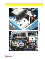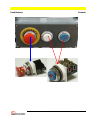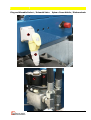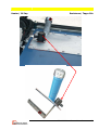
1
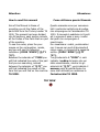
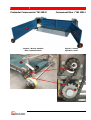
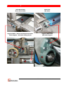
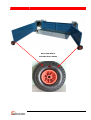
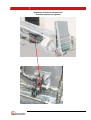
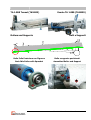
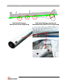
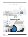
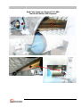
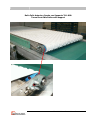
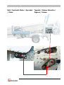
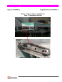
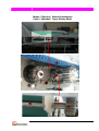
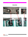
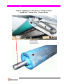
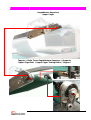
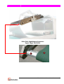
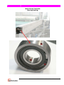
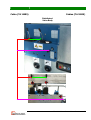
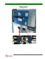
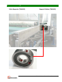
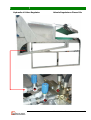
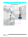
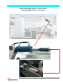
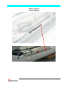
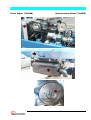
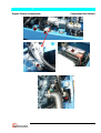
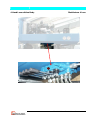
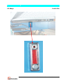
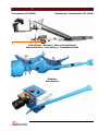
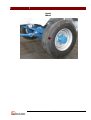
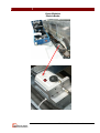
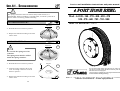
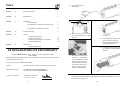
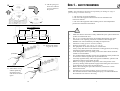
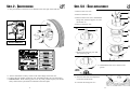
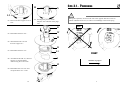
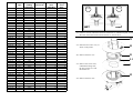
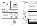
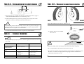
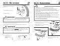
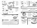
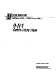
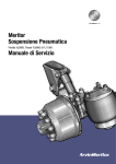
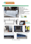
Manteinance Manual
TA 1000
Manuale Manutenzione
TA 1000
May 2006
Maggio 2006
CIEMMECALABRIA SRL
Via Bonfadina, 111
25046 Cazzago San Martino (Bs) Italy
Tel. (0039) 030 7254118
Fax (0039) 030 7759992
www.ciemmecalabria.com
Attention:
Attenzione:
How to read this manual
Come utilizzare questo Manuale
Aim of this Manual is those of
providing you all the Codes of the
parts that form the Turkey Loader TA
1000. The manual has been divided
into 08 sections, each section include
all the Codes of the Parts that are part
of the machine.
To see the codes, place the your
mouse on the red question marks,
and you will see the following
indication: (CODE *XXXX*) (Q.TY
*X*).
Between the asterisks of “CODE you
will find indicated the code of the part
that you are searching, instead
between the asterisks of ”Q.TY” you
will find indicated the pieces of this
item that you will find on the machine
TA 1000.
Questo manuale serve per conoscere
tutti i particolari sottoforma di codice,
che compongono la Caricatacchini TA
1000. Il manuale è suddiviso in 8 parti
ed in ognuna di esse vi sono i codici
dei pezzi che compongono il
macchinario.
Per visualizzare i codici, posizionatevi
con il mouse sui punti di domanda di
colore rosso, vi comparirà la seguente
scritta: (CODE *XXXX*) (Q.TY
*X*).
Tra gli asterischi di “CODE” ci sarà
indicato il codice del pezzo che voi
state visualizzando, mentre tra gli
asterischi di ”Q.TY”, verrà indicato il
numero pezzi di quell’articolo che
sono stati utilizzati per realizzare la
Caricatacchini TA 1000.
TRY NOW
INDEX
C.
INDICE
D.
B.
E.
A.
F.
Section
Sezioni
A.
Box Raccoglitore
p. 3
A.
Preloader
p. 3
B.
Canale Principale
p. 10
B.
Main Tunnel
p. 10
C.
Ingabbiatore
p. 19
C.
Cager
p. 19
D.
Cabina
p. 29
D.
Cabin
p. 29
E.
Meccanismi di sollevamento
p. 34
E.
Lifting system
p. 34
F.
Impianto Spostamento
p. 44
F.
Transfer System
p. 44
Impianto Elettrico
p. 51
Wiring system
p. 51
TA 1000 Manteinance Manual
2
Preloader Components (TA1 M01)
Tappeto / Motore Idraulico
Belt / Hydraulic Motor
Componenti Box (TA1 M01)
Pignoni / Catena
Sprocket / Chain
TA 1000 Manteinance Manual
3
Rullo Motorizzato
Motor Driver Roller
Supporto Rullo / Ruote scorrimento Pre-Loader
Roller Support / Preloader sliding wheels
Rullo Folle
Idle Roller
Supporto Rullo Folle
Idle Roller Support
TA 1000 Manteinance Manual
4
Ruota Cancelli Box
Preloader doors wheels
TA 1000 Manteinance Manual
5
Regolatore di flusso olio idraulico Box
Preloader Hydraulic oil regulator
TA 1000 Manteinance Manual
6
TA 1.000 Tunnel (TA1M03)
Rollers and Supports
Rullo Folle Posteriore con Pignone
Back Idle Roller with Sprocket
Canale TA 1.000 (TA1M03)
Rulli e Supporti
Rullo e supporto posizionati
Assembled Roller and Support
TA 1000 Manteinance Manual
10
Rulli folli di Sostegno
Idle Rollers for the Supporting
Rulli folli di Sostegno posizionati
Assembled Idle Rollers for the Supporting
TA 1000 Manteinance Manual
11
Rulli Traino e Folle con Supporti TA 1.000
Towing and idle Rollers with supports
Rullo Traino Canale con Supporto TA 1.000
Tunnel towing Roller with Support
TA 1000 Manteinance Manual
12
Rulli Folle Canale con Supporti TA 1.000
Tunnel Idle Rollers with Supports
TA 1000 Manteinance Manual
13
Rullo Folle Anteriore Canale con Supporto TA 1.000
Tunnel front Idle Roller with support
TA 1000 Manteinance Manual
14
Belt / Hydraulic Motor / Sprocket
/ Chain
Tappeto / Motore Idraulico /
Pignoni / Catena
TA 1000 Manteinance Manual
15
Further Componets
Altri Componenti
TA 1000 Manteinance Manual
16
Cager ( TA1M04 )
Ingabbiatore ( TA1M04 )
Catena / Pignone Nastro Ingabbiatore
Chain / Caging Belt Sprocket
TA 1000 Manteinance Manual
19
Catena / Pignone / Albero Spostamento
Chain / Sprocket / Cager Moving Shaft
TA 1000 Manteinance Manual
20
Motore idraulico
Hydraulic Motor
TA 1000 Manteinance Manual
21
Tappeto Ingabbiatore / Rullo Traino / Rullo di sostegno
Caging Belt / Towing Roller / Support Roller
Rullo Traino
Towing Roller
TA 1000 Manteinance Manual
22
Rullo Folle anteriore Ingabbiatore
Front Idle Roller
TA 1000 Manteinance Manual
23
Ingabbiatore Superiore
Upper Cager
Tappeto / Rullo Traino Ingabbiatore Superiore / Supporto
Upper Cager Belt / Upper Cager Towing Roller / Support
TA 1000 Manteinance Manual
24
Rollo Folle Ingabbiatore Superiore
Upper Cager Idle Roller
TA 1000 Manteinance Manual
25
Avvolgitubo a Molla
Spring Hose Reel
You can find the user manual about this part on page 56
TA 1000 Manteinance Manual
26
Anello Porta Cuscinetto
Bearing Housing
TA 1000 Manteinance Manual
27
Cabina (TA 1M05)
Cabin (TA 1M05)
Distributori
Valve Body
TA 1000 Manteinance Manual
29
Regolatori di Flusso
Flow Regulators
TA 1000 Manteinance Manual
30
Cabin Supports (TA1M12)
Supporti Cabina (TA1M12)
TA 1000 Manteinance Manual
31
Hydraulic oil Valve Regulator
Valvola Regolazione Flusso Olio
TA 1000 Manteinance Manual
32
Meccanismi di sollevamento e Telaio (TA1M02)
Frame and Lifting System
TA 1000 Manteinance Manual
34
Cilindro Brandeggio Cabina / Cavo D’acciaio
Cabin Swinging Cylinder / Iron Cable
TA 1000 Manteinance Manual
35
Cilindro Telescopico
Telescopic Cylinder
TA 1000 Manteinance Manual
36
Molla a Trazione
Traction Spring
TA 1000 Manteinance Manual
37
Pompa Doppia / Elettrovalvola a due Vie
Double Pump / Two Ways-Solenoid Valve
TA 1000 Manteinance Manual
38
Diesel Engine (TA1M08)
Motorizzazione Diesel (TA1M08)
TA 1000 Manteinance Manual
39
Engine Further Components
Componenti Vari Motore
TA 1000 Manteinance Manual
40
4 Hand Levers Valve Body
Distributore 4 Leve
TA 1000 Manteinance Manual
41
Oil Gauge
Livello Olio
TA 1000 Manteinance Manual
42
Transmission (TA 1M10)
Trasmissione Caricatacchini (TA 1M10)
Differenziale / Balestre / Albero di trasmissione
Differential Gear / Leaf Springs / Transmission Shaft
Riduttore
Gear Reducer
TA 1000 Manteinance Manual
44
Ruota
Wheel
TA 1000 Manteinance Manual
45
Freno Elettrico
Electric Brake
TA 1000 Manteinance Manual
46
Towing Eye (TA1M11)
Ralla Caricatacchini (TA1M11)
TA 1000 Manteinance Manual
47
Wiring System (TA1M07)
Impianto Elettrico (TA1M07)
TA 1000 Manteinance Manual
51
Push Buttons
Pulsanti
TA 1000 Manteinance Manual
52
Plug and Movable Socket / Solenoid Valve
Spina e Presa Mobile / Elettrovalvola
TA 1000 Manteinance Manual
53
Emergency Push Button
Pulsante Emergenza
TA 1000 Manteinance Manual
54
Heater / Oil Cap
Resistenza / Tappo Olio
TA 1000 Manteinance Manual
55
Manuale Avvolgitubo a Molla
Spring Hose Reel Manual
Sec. 6.1 - SPRING DEMOLITION
Service and installation instructions and parts manual
4 PORT HOSE REEL
!
The spring contained in each reel remains always under tension; it is
indispensable, before considering it a normal refuse, to weld in 4 points all its
turns in order to avoid any possible unwinding.
Mod. A4 320 - 340 - 370 - 400 - 420 - 470
520 - 570 - 600 -702 - 703 - 800
K
-a- INTEGRAL BAND «K»
WELDING
⇒ Weld all the turns as shown in picture 1.
Man. Nr. 890.05.04 - 2004/02
1
⇒ Dispose the material according to the local
rules in force.
K
-b- BROKEN BEND «K»
WELDING
!
2
Do not take the spring out of its
container.
The spring turns must be welded
inside the spring container.
⇒ Weld all the turns as shown in picture 2.
F
SCREWS
3
⇒ Close the spring container «D» by the
cover «F» fixing it with two screws as
shown in picture 3.
⇒ Dispose the material according to the local
rules in force.
20
Do not start working before the machine, into which the
reel will be annexed, will be declared conformity with CE
directions that can be applyed.
This manual is an integral part of the engine: the user has
to read it before starting working.
D
Demac s.r.l. - via R. Murri 14 - 20013 MAGENTA (MI) - ITALY - tel.+39.02.9784488 - fax. +39.02.97003509
Internet : www.demac.it - E-mail : [email protected]
1
INDEX
-12- Clean perfectly the
seals seats.
Page
3
Section
1
Safety precautions
Section
2
Identification
4
Section
3
Installation
3.1 Prewinding
3.2 Installation on fork lift trucks (A4 420)
5
7
3.3 Installation on telescopic cranes
8
Section
4
Trouble-shooting
Section
5
Service
5.1 Spring replacement
5.2 Hose replacement
5.3 Reversing the direction of rotation
5.4 Seals replacement
9
12
13
17
Demolition
6.1 Spring demolition
20
Section
6
S
T
8
-13- Place the new O-ring «S» and
the new Quad-ring «T» in their
grooves.
-15- Put the deformed ring in the
groove on the O-ring and
then straighten the fold by
pushing it in the seat.
-16- Calibrate the seals with a plastic mandrel, clean and lubrificated.
CE DECLARATION OF CONFORMITY
Company DEMAC S.r.l. via R. Murri 14 - 20013 MAGENTA (MI)
DECLARES
that the machines described below are in accordance with all the essential requirements
of the applicable directives
machine description:4 PORT HOSE REEL
model:
A4 320-340-370-400-420-470-520-570-600-702-703
applicable directives:
EC DIRECTIVE FOR MACHINERY
N° 98/37 EEC WITH AMENDMENTS
producer’s segnature:
DOMENICO VARANO
(Legal Rapresentative)
2
-14- Heat the plastic ring with
air or oil ( particularly
in the cold season ). Bend
the ring as shown, with
the aid of the smooth iron
rod of about 10 mm diameter. Avoid the development of sharp bends.
-17- Reassemble the hose reel following instructions in reverse order paing attention
to the position of the middle spring compared to the spring retainer ( see picture
18.2 Section 5.1 page 11 ).
19
-9- Lift the spring container «D» and turn
it over as shown in
the picture.
D
Sec. 1 -
SAFETY PRECAUTIONS
NOTE - The manufacturer declines all responsibility for damage or injury to
persons, things or animals caused by:
1- The incorrect use of the equipment.
2- The use of the equipment for aims that are not included in this
instructions manual.
3- The use of the equipment without taking note of the indispensable
precautions contained in this manual.
A4 GASKET KIT
!
O-RING
⇒
⇒
PLASTIC-RING
QUAD-RING
-10- Remove the plastic
ring «R» by a tool.
R
⇒
⇒
⇒
⇒
⇒
QUAD-RING
⇒
⇒
O-RING
⇒
-11- Take off the O-ring
and the Quad-ring
from their groove
and do not use them
again.
QUAD-RING
⇒
⇒
⇒
18
Make sure that this instruction is fully understood by the operator before the
product is installed and used.
The “A 4” is a spring return hose reel assembly designed for use where
movements occur requiring continuous variations in hose length, the
DEMAC hose reel automatically rewinding the surplus hose.
Maximum working pressure: 300 bar (30 MPa).
Working temperature: -20 / +80 °C (-4 / 176 °F).
The equipment can be delivered with or without hoses.
Always verify that the hose can tolerate the working pressure, the working
temperature and the endurance of the work.
Twin thermoplastic hoses responding to the norms SAE 100 R7 and SAE
100 R8 are recommended.
For product liability and safety reasons any modification of the product and
its accessories must be agreed upon by the manufacturer.
All locally legislated safety rules with regard to installation, operation and
maintenance must be respected at all times.
Before servicing any hydraulic component, relieve the pressure in the
system by shutting off the hydraulic supply and actuating the control levers
for all functions severals times in both directions
Before disconnecting the open end of the hose, read section 5 of this
instructions manual.
NEVER remove the band around the spring nor disturb its position.
The maximum attention while handling the spring is recommended. Read
the instructions on section 5: Servicing.
3
Sec. 2 - IDENTIFICATION
⇒ The part number of the hose reel is marked on the outer part of the shaft too.
Sec. 5.4 - SEALS REPLACEMENT
-1- Remove the cover «G» .
G
-2- Remove the hose «I1» .
W
-3- Remove the screws «W»; unthread the
flange «H», the hose support «L» and
the divider «J».
H
-4- Remove the hose «I2» .
456
123
O
P
I1
L1
J
Serial number
I2
-5- Remove the snap ring «O» and
the nylon ring «P».
-6- Unthread the hose reel as shown in the
picture
⇒ Demac name label is clearly visible on the outer flange of the hose reel.
⇒ It shows the part number of the hose reel, the model and the year of construction.
⇒ IMPORTANT When ordering parts or for any other possible request you should
always mention the specifications indicated on the name plate.
4
C
-7- Turn over the hose reel and place it
on two flat wood blocks.
-8- Unscrew the fixing nuts «C».
17
M
N
Sec. 3.1 - PREWINDING
!
L2
-23- Reverse the hose support «L2» of
180°.
-24- Exchange the position of the
adaptors «M» with that of the plugs
«N».
G
-25- Reassemble the hose «I2». .
During this operation, do not turn the reel in the opposite direction to that of
rotation indicated on the reel, in order to avoid damage to the inside spring.
NO!
W
H
-26- Thread the divider «J» and
the hose support «L».
I1
-27- Reassemble the hose «I1».
L1
-28- Assemble the divider «J», the hose
support «L» and the flange
«H»screwing the screws «W».
J
RIGHT
continue on page 6
I2
-29- Reassemble the cover «G» and
roll up the hoses «I1» e «I2».
16
5
Model
Hose
type
Hose
working
lenght max.
Prewinding
turns max.
A4 320.06
A4 320.08
1/4”
5/16”
3700
2900
2
2
4,5
3,5
10
10
A4 320.10
A4 320.12
A4 340.06
A4 340.08
A4 340.10
A4 340.12
A4 370.06
A4 370.08
A4 370.10
A4 370.12
A4 400.06
A4 400.08
A4 400.10
A4 400.12
A4 420.06
A4 420.08
A4 420.10
A4 420.12
3/8”
1/2” B1
1/4”
5/16”
3/8”
1/2”
1/4”
5/16”
3/8”
1/2”
1/4”
5/16”
3/8”
1/2”
3000
2200
4700
3900
3700
2200
5700
5000
4200
3200
7000
6200
5300
4200
3
4
2
3
4
4
2
2
3
4
1
2
2
3
4
3
5,5
4,5
4,5
3
6,5
6,5
5
3,5
7,5
6,5
6
5
10
10
10
10
10
10
10
10
10
10
10
10
10
10
A4 470.06
A4 470.08
A4 470.10
A4 470.12
1/4”
5/16”
3/8”
1/2”
1/4”
5/16”
3/8”
1/2”
8100
7500
6200
4200
11000
9500
9000
7000
3
3
4
5
2
2
3
5
8,5
8
6.5
5
11,5
9,5
9
7
14
14
14
14
14
14
14
16
A4 520.06
A4 520.08
A4 520.10
A4 520.12
A4 570.06
A4 570.08
A4 570.10
A4 570.12
A4 600.06
A4 600.08
A4 600.10
A4 600.12
A4 702.06
A4 702.08
A4 702.10
A4 702.12
A4 702.10
A4 703.10
A4 800.10
1/4”
5/16”
3/8”
1/2”
1/4”
5/16”
3/8”
1/2”
1/4”
5/16”
3/8”
1/2”
1/4”
5/16”
3/8”
1/2”
3/8”
3/8”
3/8”
14000
12000
10700
8500
17000
15000
13000
10200
20500
16500
15500
12000
26500
21500
19500
15000
22700
20500
25500
1
2
2
4
3
4
3
8
2
5
4
6
3
3
3
4
4
2
5
13
11
9,5
8
14,5
13
11
9
16,5
13,5
11
10
16,5
13,5
12,5
10
16
13
15.5
14
14
14
14
16
16
16
16
16
22
16
16
16
16
16
16
22
16
22
6
Turns for
hose
unwinding
Spring
turns
max.
17.2
17.1
LEFT
RIGHT
-18- Follow in reverse order the instructions of Section 5.1 indicated at point 13 and 12;
after that, follow the instructions of Section 5.1 from 18 to 19.
W
-19- Place the hose reel in vice, as
shown in the picture.
H
-20- Remove the hose «I1» .
I1
L1
J
-21- Remove the screws «W»;
unthread the flange «H»,
the hose support «L» and
the divider «J».
I2
-22- Remove the hose «I2» .
15
F
Sec. 3.2 - INSTALLATION ON FORK LIFT TRUCKS
D
( A4 420 )
-1- Place the hose reel in the highest position
possible so that after the hose reel has been
installed, the flanges do not jut out from
mast.
-2- Verify that when the mast is completely
tilted backwards and that there remains
sufficient space «A» of 50 mm.
-3- Verify that clearance «B» is:(See tab.1)
-4- Position the swivel joint or the crocodile
joint «C», making sure that it is aligned
with the hose reel.
-5- After the reel has been installed, prewind it
as indicated in the table on page 4.
D
-14- Place the cover «F» on the container
«D» as shown in the picture.
-15- Turn over the spring container
and raise part «D».
!
The band around the spring must never be removed or its position disturbed.
Maximun attention is recommended while handling the spring in order to avoid any
possible ejection from the band.
B
IMPORTANT - DO NOT WIND THE REEL
IN THE WRONG DIRECTION, BECAUSE IT
COULD CAUSE DAMAGE TO THE
SPRING.
A
-16- Install the spring in the
container «D» in the new
direction of rotation of the
hose reel (see the picture).
RIGHT
LEFT
X
-6- Connect the open end of the hoses to the
carriage.
-7- Connect the feeder hoses to the hydraulic
control valve «D».
-8- Make some full lifting and lowering
cycles of carriage and be carefull that
winding of hoses is correct.
D
C
Hose
size
«B» min.
(mm)
1/4”
50
NB-For hose reel left see picture 17.1
5/16”
60
For hose reel right see picture 17.2
3/8”
70
1/2”
80
Y
-17- Remove the screw «X»; remove the
spring retainer «Y» of 180° degrees.
Tab.1
14
7
Sec. 3.3 - INSTALLATION ON TELESCOPIC CRANES
Sec. 5.3 - CHANGE OF THE DIRECTION OF ROTATION
Z
UV
-1- Place the hose reel, provided with the hose, in the desired position, trying to
reduce the minimum clearance «Z» as much as you can.
-2- After assembling the reel, prewind it by turning it for as many turns in the
direction of rotation as indicated in the table in Section 3.1.
!
LEFT
RIGHT
Follow the instructions of Section 5.1 from 1 to 12.
F
The prewinding turns are the total number of turns that the operator must apply to
the reel in the direction of the arrow “ROTATION” in order to fasten the free
end of the hose «U» to point «V» of the machine.
-3- Connect the free end of the hose «U» to point «V» of the machine.
Sec. 4 - TROUBLE - SHOOTING
E
-13- Remove the screw «E» and lift
the cover «F».
!
Before performing any repair operation, read thoroughly the manual at the section
“Servicing”.
PROBLEM
PROBABLE CAUSE
CORRECTIVE ACTION
⇒
⇒
Hose reel spring broken
Hose reel spring damaged
⇒
⇒
Inadequate prewind of the spring
⇒
⇒
Hose reel and junction block not in
alignment
Flanges deformed
OIL LEAKS AT HUB
⇒
OIL LEAKS AT ADAPTORS
⇒
HOSE REEL WINDING
ACTION IS JAMMED OR
WORKS WRONGLY
HOSE JUMPING OFF THE
REEL
EXCESSIVE WEAR ON HOSES
⇒
Replace the spring
!
Before proceeding, check the integrity of the band «K» around the spring.
• If it is integral follow the instructions from point 14 to 29.
Control the prewinding turns in the
table of Section 3.1, page 5
⇒
⇒
Align reel and junction block
Replace the flanges
Worn seals
⇒
Replace the seals
Loose adaptors
⇒
Tighten the adaptors
8
K
• If it is broken, demolish the spring following the instructions as indicated to point
b of Sec. 6.1. Order a new spring and a new spring container and follow the
instructions from point 16 to 29.
13
Sec. 5.1 - SPRING REPLACEMENT
Sec. 5.2 - HOSE REPLACEMENT
Follow the instructions of Section 5.1
from 1 to 6.
!
G
-7- Disassemble the cover «G».
-8- Replace the hose.
! WARNING
During this operation, do not turn the reel in the opposite direction to that of
rotation indicated on the reel, in order to avoid damage to the inside spring.
-1- Cold working is recommended when operating the machine.
-2- Bring the machine to its rest position with its jibs completely lowered.
-3- Relieve the pressure in the system by shutting off the electric and the
hydraulic supply and actuate the control levers for all functions several times
in both directions.
-4- The hose reel spring is prewound when mounted in order to hold the hoses
under tension. Before loosening the adaptors at the open end of the hoses,
block the reel with the help of a second operator.
-5- Disconnect the adaptors at the open end of the hose, gathering the discharged
oil to avoid the contamination of the surroundings.
-6- Allow to run down the prewinding of the spring, making the reel turn slowly
to a stop. NOTE: count the turns made before the stop to be able to give the
same number of turns of prewinding.
-7- Remove the hose reel from the machine.
-8- Place the hose reel in vice, as shown in the
picture. Remove the screws .
- 9 - Put the cover «G» in its former position.
-10- Prewind the spring as many turns as indicated in par.6 of the Section 5.1
B
G
-9- Remove the screws «A», the screws «B»
and take the cover «G» off.
! WARNING
We mean “prewindings turns” the total number of turns that the operator must
apply on the hose reel, in the direction of the arrow “ROTATION”, to fasten the
free end of the hose «U» with the point «V» of the machine.
-11- Connect the free end
of the hose «U» to
the point «V» of the
machine.
UV
12
O
A
P
-10- Remove the snap ring «O» and the
nylon ring «P».
9
11.1
11.2
-11- Unthread
the hose reel
as shown in
picture11.1
and place it
overturned
as shown in
the picture
11.2
-12- Unscrew the
fixing nuts
«C» from the
spring container «D» and
turn it over as
shown in the
picture.
C
D
F
D
!
The band around the spring must never be removed or its position disturbed.
Maximun attention is recommended while handling the spring in order to avoid any
possible ejection from the band.
-16- Install the spring in the
container «D» in the direction
of rotation marked on the hose
reel.
-13- Remove the screw «E» and lift the
cover «F».
E
-18- Thread the shaft in
the hose reel as
shown in picture
18.1 in order that the
middle of the spring
is placed in the
spring retainer as
shown in picture
O
P
!
WARNING
K
Before proceeding, check the integrety of the band «K» around the spring.
• If it is integral follow instructions as indicated at points 14 and 15 and
demolish the spring as indicated at point a of Sec. 6.1
• If it is broken follow instructions as indicated at point b of Sec. 6.1
10
RIGHT
LEFT
-17- Follow in reverse order the instructions indicated at point 13 and 12.
18.2
F
D
-14- Place the -15- Turn over
cover «F»
the spring
on the
container
container
and raise
«D» as
part «D».
shown in
picture.
-20- Reassemble
the cover
«G»
screwing
the screws
«A» e «B».
-19- Turn over the hose reel
and reassemble the nylon ring «P» and the
snap ring «O».
11
18.1
B
A
G
Ricambi - Spare parts Ersatzteile Pieces de rechange
A4 320 - 340 - 370 - 400
Data versione: 19/03/2004
SPECIFICARE SEMPRE IL NUMERO DI MATRICOLA DELL’APPARECCHIO
INDIQUER LE NUMERO DE MATRICULE DE L’ENROULEUR
ALWAYS MENTION SERAIAL NUMBER OF THE REEL
ANGEBEN SIE IMMER DIE REGISTRIERNUMMER DER SCHLAUCHROLLE
N° Q.tà
CODICE
I
GB
D
POS. Q.ty
CODE
DESCRIZIONE
DESCRIPTION
TEIL
F
Valido per / used on
DENOMINATION 320
1
1
500.05.00
ALBERO
SHAFT
WELLE
ARBRE
2
1
510.06.13
MOZZO
HUB
NABE
MOYEN
3
1
520.07.02
FLANGIA INT.
INNER FLANGE
INNENFLANSCH
BRIDE INT.
4
1
530.08.02
DIAFRAMMA
DIVIDER
MITTLERE TRENNWAND
DIVISOIRE
5
1
540.09.02
FLANGIA EST.
OUTER FLANGE
AUSSENFLANSCH
BRIDE EXT.
6
1
660.02.00
SCATOLA MOLLA
SPRING CONTAINER
FEDERGEHÄUSE
BÔITE DE RESSORT
7
1
101.01.01
MOLLA
SPRING
FEDER
RESSORT
8
1
570.03.00
FERMO MOLLA
SPRING RETAINER
FEDERARRETIERUNG
MOYEN DE RESSORT
9
1
560.02.00
SUPPORTO
SUPPORT
TROMMELHALTER
SUPPORT
10
4
620.01.15
VITE
CAPSCREW
SCHRAUBE
VIS
11
1
610.05.00
GUARNIZIONE
SEAL
DICHTUNGEN
JOINT
12
1
620.01.03
GRANO
SETSCREW
SCHRAUBE
ECROU
13
1
550.01.13
COPERCHIO
COVER
DECKEL
COUVERCLE
14
1
600.09.00
ANELLO D'ARRESTO
CIRCLIP
SEEGERRING
BAGUE D’ARRÊT
15
1
580.02.00
ANELLO
RING
RING
BAGUE
16
8
650.02.03
RONDELLA
WASHER
SCHEIBE
RONDELLE
17
4
630.01.01
RACCORDO
ADAPTOR
ANSCHLUB
RACCORD
18
4
640.01.01
TAPPO
PLUG
SCRHRAUBENVERSCHLUß
BOUCHON
19
5
620.01.00
VITE
CAPSCREW
SCHRAUBE
VIS
* 20
1
201.05.40
KIT GUARNIZIONI
GASKET - KIT
SATZ DER DICHTUNGEN
KIT JOINT
21
1
201.05.12
OR 48x2
OR 48x2
OR 48x2
OR 48x2
22
1
201.05.42
OR 2250
OR 2250
OR 2250
OR 2250
340
370
* Da matricola n° 54386 in poi - From serial number 54386 - Depuis N° de matricule 54386 - Von registriernummer 54386
Ricambi consigliati - Recommended spare parts - Pieces de rechange conseillées - Geratene Ersatzteile
DEMAC S.r.l. - 20013 MAGENTA (MI) - Via R. Murri, 14 - Tel. +39.02.9784488 - Fax +39.02.97003509
www.demac.it - E-mail: [email protected]
400