1
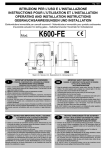
ISTRUZIONI PER L’USO E L’INSTALLAZIONE
INSTRUCTIONS POUR L’UTILISATION ET L’INSTALLATION
OPERATING AND INSTALLATION INSTRUCTIONS
GEBRAUCHSANWEISUNGEN UND INSTALLATION
Mod.
K10
Misure in mm - Mesures en mm - Measurements in mm - Abmessungen in mm
I
IMPORTANTI ISTRUZIONI PER LA SICUREZZA
ATTENZIONE - É IMPORTANTE PER LA SICUREZZA DELLE PERSONE
CHE VENGANO SEGUITE TUTTE LE ISTRUZIONI
CONSERVARE CON CURA QUESTE ISTRUZIONI
1° - Tenete i comandi dell’automatismo (pulsantiera, telecomando etc.) fuori dalla portata dei bambini.
I comandi devono essere posti ad un’altezza minima di 1,5mt dal suolo e fuori dal raggio d’azione
delle parti mobili.
2° - Effettuare le operazioni di comando da punti ove l’automazione sia visibile.
3° - Utilizzare i telecomandi solo in vista dell’automazione.
4° - Avvertenze: Sulle altre misure di Protezione contro rischi attinenti l’installazione o l’utilizzazione
del Prodotto vedi, a completamento di questo libretto di Istruzioni, le Avvertenze RIB allegate.
Qualora queste non siano pervenute chiederne l’immediato invio all’Ufficio Commerciale RIB.
LA DITTA RIB NON ACCETTA NESSUNA RESPONSABILITÀ per eventuali danni provocati dalla
mancata osservanza nell’installazione delle norme di sicurezza e le leggi attualmente in vigore.
F
INSTRUCTIONS IMPORTANTES POUR LA SECURITE
IL EST IMPORTANT POUR LA SECURITE DES PERSONNES
DE SUIVRE ATTENTIVEMENT TOUTES INSTRUCTIONS
GARDER MODE D’EMPLOI
1° - Gardez les commandes de l’automatisme (boutons poussoirs, telecommande etc.) hors de la
portée des enfants. Les commandes doivent être placées au minimum à 1,5 m du sol, et hors de
rayon d’action des pièces mobiles.
2° - Il faut donner les commandes d’un lieu, où on peut voir l’automatisme.
3° - Il faut utiliser les émetteurs seulement si on voit le portail.
4° - Avertissements: Sur les autres mesures de Protection contre les risques relatifs a l’installation ou
l’utilisation du Produit, voir, à titre de complément de ce livret d’instructions, les Avertissements
RIB ci-jointes. Dans le cas où celles-ci ne vous seraient pas parvenues, en demander l’envoi
immédiat au Bureau Commercial Etranger RIB (Ufficio Commerciale Estero RIB).
L’entreprise R.I.B. n’accepte aucune responsabilité pour des dommages éventuels
provoqués par le manque d’observation lors de l’installation des normes de sécurité et lois
actuellement en vigueur.
GB
IMPORTANT SAFETY INSTRUCTIONS
WARNING - IT IS IMPORTANT FOR THE SAFETY OF PERSONS
TO FOLLOW ALL INSTRUCTIONS
SAVE THESE INSTRUCTIONS
1° - Keep the automatism control (push-button, remote control, etc) out of the reach of children. The
control systems must be installed at a minimum height of 1.5 mt from the ground surface and not
interfere with the mobile parts.
2° - Command pulses must be given from sites, where You can see the gate.
3° - Use transmitters only if You can see the gate.
4° - Warnings: when you have finished reading this instruction booklet, please refer to the RIB
instructions attached for the other precautionary measures against risks connected with the
installation or use of the product. If you have not received these, ask RIB Export Office to send
them immediately.
R.I.B. accepts IS NOT LIABLE for any damage caused by the not abiding of the safety regulations
and laws at present in force not being observed during installation.
D
WICHTIGE GEBRAUCHSANWEISUNGEN FÜR DIE SICHERHEIT
ACHTUNG - UM PERSONEN VOLLKOMMEND GARANTIEREN ZU KöNNEN IST ES
WICHTIG DASS ALLE INSTALLLATIONSVORSCHRIFTEN BEOBACHTET WERDEN
1° - Bewahren Sie die Geräte für die automatische Steuerung (Drucktaster,
Funksender, u.s.w.) an einem für Kinder unzugänglichen Platz auf. Die Steuerungen müssen
mindestens auf einer minimal Höhe von 1,5 mt gestellt werden und sich ausserhalb der Raum der
bewegenden Teile befinden.
2° - Die Betätigung der automatischen Steuerungs soll nur ausgeführt werden wenn die automatische
Anlage sichtbar ist.
3° - Die Funksender nur inn den Fällen benützen wenn die automatische Anlage sichtbar ist.
4° - Achtung: Für weitere Schutzmaßnahmen im Rahmen der Installation und Anwendung der
Produkte siehe die beiliegenden RlB-Sicherheitshinweise, die diese Gebrauchsanleitung
ergänzen. Sollten Sie diese nicht erhalten haben, fördern Sie sie bitte sofort bei der RlB
Exportabteilung an. Die Firma R.I.B. haftet nicht für eventuelle Schäden, die bei der
Installation durch Nichtbeachtung der zur Zeit gültigen Sicherheitsvorschriften vertrommen
entstanden sind.
I
IMPORTANTI ISTRUZIONI DI SICUREZZA
PER L’INSTALLAZIONE
ATTENZIONE - UNA SCORRETTA INSTALLAZIONE PUÓ PORTARE A DANNI RILEVANTI
SEGUIRE TUTTE LE ISTRUZIONI PER UNA CORRETTA INSTALLAZIONE
1° - Questo libretto d’istruzioni è rivolto esclusivamente a del personale specializzato che sia a
conoscenza dei criteri costruttivi e dei dispositivi di protezione contro gli infortuni per i cancelli, le
porte e i portoni motorizzati (attenersi alle norme e alle leggi vigenti).
2° - Se non é previsto nella centralina elettrica, installare a monte della medesima un’interruttore di tipo
magnetotermico (onnipolare con apertura minima dei contatti pari a 3mm) che riporti un marchio di
conformità alle normative internazionali.
3° - Per la sezione ed il tipo dei cavi la RIB consiglia di utilizzare un cavo di tipo NPI07VVF con sezione
minima di 1,5mm2 e comunque di attenersi alla norma IEC 364 e alle norme di installazione vigenti
nel proprio Paese.
F
IMPORTANT MODE D’EMPLOI DE SECURITE
POUR L’INSTALLATION
ATTENTION - UNE INSTALLATION INCORRECTE PEUT CAUSER DE GRANDS
DOMMAGES - SUIVRE TOUTES INSTRUCTIONS POUR UNE CORRECTE INSTALLATION
1° - C e manuel d’instruction est adresse seulement au personnel specialisé qui a une
connaissance des critères de construction et des dispositifs de protection contre les accidents en
ce qui concerne les portails, les portes et les portes cochères motorisees (suivre les normes et les
lois en vigueur).
2° - A fin de proceder al’entretien des parties electriques, connecter à l’installation un distonteur
differentiel magneto thermique (qui disconnait toutes les branchements de la ligne avec ouverture
min. des branchements de 3 mm ) et qui soit conforme aux normes internationales.
3° - Pour la section et le type des câbles à installer nous vons conseillons di utiliser un cable NPI07VVF
avec une section min de 1,5 mm2 en respectant quand même la norme IEC 364 et les normes
nationales d’installation.
GB
IMPORTANT SAFETY INSTRUCTION
FOR INSTALLATION
WARNING -INCORRECT INSTALLATION CAN LEAD TO SEVERE INJURY
FOLLOW ALL INSTALLATION INSTRUCTIONS
1° - This instruction booklet is exclusively dedicated to specialized staff who are aware of the
construction criteria and of the accident prevention protection devices for motorized gates and
doors (according to the current regulations and laws).
2° - To maintain electrical parts safely it is advisable to equip the installation with a differential thermal
magnetic switch (onnipolar with a minimum opening of the contacts of 3mm) and must comply
with the international rules.
3° - As for electric cable type and section RIB suggests cable type NPI07VVF with minimum section
of 1,5mm2 and however respect IEC 364 rule and general national security regulations.
D
WICHTIGE SICHERHEITSVORSCHRIFTEN
FÜR DIE INSTALLATION
ACHTUNG - EINE FALSCHE INSTALLATION KANN ZU BEDEUTENDE SHADEN FÜHREN.
FÜR EINE KORREKTE ANLAGE ALLE GEBRAUCHSANWEISUNGEN FOLGEN
1° - Diese Montageanweisung kann ausschließlich von der Fachleuten gebraucht werden, die
die Instandsetzung und die Schutzvorrichtungen zur Verhinderung von Unfällen bei motorisierten
Toren kennen (nach die aktuellen Normen und Gesetze).
2° - F ür die Wartung der elektrischen Teile ist es ratsam, zwischen der Anlage und dem
Netzanschluß einen magnetisch-thermischen Differenzialschalter (mit der minimale Öffnung allen
Kontakte von 3 mm) unterbricht die ein Konformitätzeichen aller internationaler Normen vorträgt.
3° - Für den Kabelguerschnitt und die Kabeltypen halten Sie sich an den Normen IEC 364 (minimale
Kabelquerschnitt von der 1,5 mm2 mit der Bezeichnung NPI07VVF) und für die Montage an die
Normen des jeweiligen Landes.
A - Elettroriduttore K10
B - Fotocellule esterne
C - Cremagliera
D - Selettore a chiave
E - Antenna radio
F - Lampeggiatore
H - Colonnina portafotocellula zincata
I - Fotocellula per protezione interna
L - Costa meccanica fissa sulle colonne
M - Costa pneumatica in punta al cancello
A - Electro-reducteur K10
B - Photocellules p/protec. externe
C - Cremaillere
D - Selecteur
E - Antenne radio
F - Signal electrique
H - Poteau zingué p/cellule ne
I - Photocellules p/protection interne
L - Cordon mécanique fixé sur pilier
M - Cordon pneumatique sur portail
A - K10 operator B - Photoelectric cells (external) C - Rack
D - Key selector
E - Tuned aerial
F - Flashing lamp
H - Galvanized column for P.E. cells
I - Photo electric cells (internal)
L - Safety strip fixed to column
M - Pneumatic safety strip on edge of gate
A - Torantrieb K10
B - Photozelle Toraussenseitig
C - Zahnstange
D - Schlusselschalter
E - Antenne
F - Blinkleuchte
H - Verzinkte Metallsäule als Photozellentrager
I - Photozelle - Torinnenseitig
L - Sicherheitskontaktleiste auf dem Schiebetor
M - Pneumatische Sicherheitskontaktleiste
I
Fig. 2
CONTROLLO PRE-INSTALLAZIONE
N.B. È obbligatorio uniformare le caratteristiche del cancello alle norme
e leggi vigenti.
É necessario che la guida abbia alle sue estremità due fermi meccanici (L) (Fig. 2).
Inoltre, le colonne devono avere superiormente delle guide antideragliamento (Fig. 3).
Il cancello deve essere protetto da involontari sganciamenti.
N.B.: Eliminare fermi meccanici del tipo indicato descritto in figura 3.
Non devono essere presenti, al di sopra del cancello, fermi meccanici perché non
sufficientemente sicuri.
Fig. 3
GB
PRE-INSTALLATION CHECKS
ATTENTION: It is compulsory to conform the gate characteristics to the
current regulations and laws.
The guide needs to have two mechanical stops (L) of the type indicated at its ends (Fig.
2).
In addition, the columns must have anti-deraillement guides at the top (Fig. 3).
The gate must be protected against unintentional derailment.
N.B. Eliminate the mechanical stops of the type indicated in Fig. 3.
There must be no mechanical stops above the gate, as they are not safe enough.
F
CONTROLE PRE-INSTALLATION
N.B.: Il est obligatoire d’adapter les caracteristiques du portail aux
normes et lois en vigueur.
Il est nécessaire que le guidage ait à ses extrémités deux arrêts mécaniques (L) du
type indiqué (Fig. 2). En plus, les colonnes doivent avoir dans la partie supérieure des
guidages antidéraillement.
Eliminer les arrêts mécaniques du type décrit (Fig. 3).
Le portail doit être protégé contre des décrochages involontaires.
Ces arrêts mécaniques ne doivent pas être présents au-dessus du portail, car ils ne son
pas suffisamment sûrs.
PRÜFUNG VON DER MONTAGE
D
ACHTUNG: Mann ist verpflichtet die Eigenschaften des Gittertures zu
die Gesetznormen in Einklang zu bringen.
Die Führungsschiene muß an beiden Enden mechanische Sperrunger (L) haben,
wie in der Abbildung dargestellt ist (Fig. 2). Darüberhinaus Mußen die Saulen über
Entgleisungsschutzvorrichtungen verfugen (Fig. 3).
Das Gitter soll gegen unvorgesehenes Entkuppeln geschützt sein.
Bitte beachten Sie: Entfernen Sie die beschriebenen mechanischen Sperrungen.
Über das Gittertor dürfen sich keine mechanischen Sperrungen befinden, da diese nicht
sicher genug sind.
CARATTERISTICHE
TECNICHE
CARACTERISTIQUES
TECNIQUES
TECHNICAL
DATA
TECHNISCHE
EIGENSCHAFTEN
Peso max cancello
Poids maxi du portail
Max. leaf weight
Max. Torgewicht
Kg
1000
Velocità di traino
Vitesse de traction
Operating speed
Laufgeschwindigkeit
m/sec
0,173
Forza max di spinta
Force maxi de poussée
Thrust force
Max. Schubkraft
N
1060
Cremagliera modulo
Module crémaillère
Rack
Zahnstange Modul
4
Alimentazione e frequenza CEE
Alimentation et frequence CEE
EEC Power supply
Stromspannung und frequenz CEE
Potenza motore
Puissance moteur
Motor capacity
Motorleistung
W
290
Assorbimento
Absorption
Power absorbed
Stromaufnahme
A
1,4
Condensatore
Condensateur
Capacitor
Kondensator
µF
n° di cicli
Nbre de cycles
No. cycles
Anzahl der Zyklen
n°
Alimentazione e frequenza
Alimentation et frequence
Power supply
Stromspannung und frequenz
Potenza motore
Puissance moteur
Motor capacity
Motorleistung
W
300
Assorbimento
Absorption
Power absorbed
Stromaufnahme
A
1,5
Condensatore
Condensateur
Capacitor
Kondensator
µF
n° di cicli
Nbre de cycles
No. cycles
Anzahl der Zyklen
n°
Alimentazione e frequenza
Alimentation et frequence
Power supply
Stromspannung und frequenz
Potenza motore
Puissance moteur
Motor capacity
Motorleistung
W
320
1,4
16
K10
220-230V~ 50Hz
16
4 - 120s/2s
220V~ 60Hz
16
7 - 120s/2s
240V~ 50Hz
Assorbimento
Absorption
Power absorbed
Stromaufnahme
A
Condensatore
Condensateur
Capacitor
Kondensator
µF
n° di cicli
Nbre de cycles
No. cycles
Anzahl der Zyklen
n°
Alimentazione e frequenza
Alimentation et frequence
Power supply
Stromspannung und frequenz
Potenza motore
Puissance moteur
Motor capacity
Motorleistung
W
330
Assorbimento
Absorption
Power absorbed
Stromaufnahme
A
3,2
Condensatore
Condensateur
Capacitor
Kondensator
µF
n° di cicli
Nbre de cycles
No. cycles
Anzahl der Zyklen
n°
Alimentazione e frequenza CEE
Alimentation et frequence CEE
EEC Power supply
Stromspannung und frequenz CEE
3 - 120s/2s
110V~ 60Hz
60
6 - 120s/2s
380-400V 3~ 50Hz
Potenza motore
Puissance moteur
Motor capacity
Motorleistung
W
470
Assorbimento
Absorption
Power absorbed
Stromaufnahme
A
1,25
n° di cicli
Nbre de cycles
No. cycles
Anzahl der Zyklen
n°
Alimentazione e frequenza
Alimentation et frequence
Power supply
Stromspannung und frequenz
Potenza motore
Puissance moteur
Motor capacity
Assorbimento
Absorption
n° di cicli
Nbre de cycles
Alimentazione e frequenza
Potenza motore
12 - 120s/2s
380V 3~ 60Hz
Motorleistung
W
300
Power absorbed
Stromaufnahme
A
No. cycles
Anzahl der Zyklen
n°
Alimentation et frequence
Power supply
Stromspannung und frequenz
Puissance moteur
Motor capacity
Motorleistung
W
Assorbimento
Absorption
Power absorbed
Stromaufnahme
A
n° di cicli
Nbre de cycles
No. cycles
Anzahl der Zyklen
n°
Alimentazione e frequenza
Alimentation et frequence
Power supply
Stromspannung und frequenz
Potenza motore
Puissance moteur
Motor capacity
Motorleistung
W
Assorbimento
Absorption
Power absorbed
Stromaufnahme
A
n° di cicli
Nbre de cycles
No. cycles
Anzahl der Zyklen
n°
1,15
25 - 120s/2s
415V 3~ 50Hz
300
0,75
100 - 120s/2s
220V 3~ 60Hz
Lubrificazione a grasso
Graisse
Grease
Schmiere
Peso max
Poids maximun
Weight of electroreducer
Motorgewicht
Kg
Rumorosità
Bruit
Noise
Geräusch
db
Volume
Volume
Volume
Volumen
m3 Grado di protezione
Indìce de protection
Protection
Schutzart
IP
400
1,9
25 - 120s/2s
Bechem - RHUS 550
25
<70
0,043
557
I
GB
N° cicli = Numero di manovre complete minime garantite (apre+chiude),
ammettendo un tempo massimo di funzionamento di 120 secondi con 2
secondi di pausa tra i movimenti (tempo massimo di funzionamento e
tempo minimo di pausa tra le manovre settati su centralina RIB S111).
No. cycles = minimum number of guaranteed complete movements
(open+close), allowing 120 seconds maximum operating time with a
two second pause between movements (maximum operating time and
minimum pause time for the movements set on the RIB S111 control board).
Il N° cicli aumenta quanto più breve è il tempo di funzionamento e lungo il tempo di
pausa tra le manovre.
The number of cycles increases as the operation time decreases, with respect to the
pause time between movements.
N° cicli = N° di manovre complete conteggiate fino al raggiungimento di una temperatura del motore di 125°C (con motore a pieno carico con temperatura di avvio
di 25°C).
No. cycles = number of complete movements carried out before the motor temperature
reaches 125°C (with motor at full load and starting temperature of 25°C).
N° cicli = Non indica che il motore subito dopo aver eseguito queste manovre vada in
termica.
F
No. cycles = the motor shows no sign of overheating after completing these cycles.
D
Nbre de cycles = Nbre minimum de manoeuvres complètes garanties
(ouverture + fermeture), en admettant un temps maximum de
fonctionnement de 120 secondes avec 2 secondes de pause entre les
mouvements (temps maximum de fonctionnement et temps minimum de pause entre les
mouvements programmés sur le coffret électronique RIB S111).
Anzahl der Zyklen = Mindestanzahl der garantierten kompletten
Bewegungen (Öffnen + Schließen), wobei die max. Betriebszeit 120
Sekunden mit 2 Sekunden Pause zwischen den Bewegungen (auf der
Steuertafel RIB S111 programmierte max. Betriebszeit und minimale Pause zwischen
den Bewegungen).
Plus le temps de fonctionnement est bref et plus le temps de pause entre les
manoeuvres est long, plus le nombre de cycles augmente.
Die Zyklenanzahl erhöht sich, wenn die Betriebszeit kürzer und die Pause zwischen den
Bewegungen länger wird.
Nbre de cycles = Nbre de manoeuvres complètes comptées avant que le moteur n’ait
atteint une température de 125 °C (avec moteur à pleine puissance et température de
démarrage de 25 °C).
Anzahl der Zyklen = Anzahl der kompletten Bewegungen bis der Motor eine Temperatur
von 125°C erreicht (bei voller Motorleistung mit einer Anfangstemperatur von 25°C).
Nbre de cycles = Ne signifie pas que le moteur se met en veille immédiatement après
l’exécution de ces manoeuvres.
I
FISSAGGIO MOTORE E CREMAGLIERA
F
INSTALLATION DU MOTOR E DE LA CREMAILLERE
La base dell’elettroriduttore K10 è dotata di 4 zanche così da poterlo
cementare al suolo.
La cremagliera va fissata a una certa altezza rispetto alla piastra di fissaggio del motore.
Questa altezza può essere variata grazie a delle asole presenti sulla cremagliera.
Le cremagliere non devono essere saldate, ma solo fissate con delle viti filettate al
cancello.
La registrazione in altezza viene fatta affinché il cancello durante il movimento, non si
appoggi sull’ingranaggio di trazione del riduttore (Fig. 4,5).
Per fissare la cremagliera sul cancello si eseguono dei fori di Ø 7 mm e si filettano
utilizzando un maschio del tipo M8.
L’ingranaggio di traino deve avere circa da 0,5 a 1 mm di agio rispetto alla cremagliera.
La base du moto-réducteur est équipée de 4 agrafes pour pouvoir être
cimentée au sol.
La crémaillère doit être fixée à une certaine hauteur par rapport à la base du moteur.
Cette hauteur peut être modifiée grâce à des boutonnières qui sont présentes sur la
crémaillère.
La crémaillère ne doit pas être soudée mais seulement fixée avec des vis filetées à la
grille.
Le réglage en hauteur est effectué afin que le portail ne s’appuie pas sur l’engrenage de
traction du réducteur (Fig. 4,5).
Afin de fixer la crémaillère sur la grille, on perce des trous de 7 mm de diamètre et on les
filètent en employant un tarand du type M8.
L’engrenage de tirage doit avoir un jeu de 0,5 à 1 mm en rapport à la crémaillère.
Fig. 4
Anzahl der Zyklen = Zeigt nicht an, daß der Motor sofort nach diesen Bewegungen
blockiert wird.
GB
MOTOR AND RACK INSTALLATION
D
INSTALLATION DES ANTRIEBS UND DER ZAHNSTANGE
The base of the ratiomotor is equipped with 4 anchors so that it can be
cemented to the ground.
The rack must be fixed at a certain height with respect to the motor base.
This height can be varied thanks to the slots on the rack.
The rack must not be welded, but simply fixed to the gate with threaded screws.
The height needs to be adjusted so that the gate does not rest on the reduction unit
traction gear (Fig. 4,5).
Holes with a diameter of 7 mm should be made to fix the rack into the gate, and they
should be threaded using a M8 type screw tap.
The pinion must have a clearance of 0,5 to 1 mm with respect to the rack.
Die Antriebsverankerungsplatte hat 2 Hacken, um sie auf Boden zu
befestigen.
Die Zahnstange muß in bestimmten Abstand von der Verankerungsplatte befestigt
werden.
Die Höhe kann mit Hilfe der auf der Zahnstange befindlichen Ösen verstellt werden.
Die Zahnstange darf nicht angeschweißt, sondern nur mit Hilfe von Gewindeschrauben
an dem Gittertor befestigt werden.
Die Höheneinstellung soll verhindern, daß das Gittertor auf dem Antriebszahnrad des
Antriebes aufliegt. (Fig. 4,5).
Um die Zahnstange am der Gittertor fixieren werden Locher mit einem Durchmesser von
7 mm gebohrt, in die ein Gewinde M8 eingeschnitten wird.
Das Zugzahnrad muß gegen über der Zahnstange ein Spiel von 0,5 bis 1 mm haben.
Fig. 5
A) Cancello
Portail coulissant
Sliding gate
Schiebetoren B) Fotocellule esterne
Cellules pour l’exterieur
External photo‑electric cells
Photozelle ‑ Außenseitig
L) Costa meccanica fissa sulle colonne
Cordon mécanique fixé sur pilier Safety strip fixed to column
Sicherheitskontaktleiste auf dem Schiebetor
I) Fotocellula per protezione interna
Photocellules p/protection interne
Photo electric cells (internal)
Photozelle ‑ Torinnenseitig
Fig. 6
I
SICUREZZE ELETTRICHE
F
SECURITES ELECTRIQUES
Per un cancello scorrevole con peso superiore a 300 Kg è obbligatorio
installare 2 coppie di fotocellule e coste in numero sufficiente a coprire
eventuali punti di schiacciamento e convogliamento (Fig. 6). Le fotocellule devono
essere poste a un altezza variabile da 40 a 60 cm. Una coppia di fotocellule devono
essere poste all’interno dell’abitazione e coprire l’intera corsa del cancello. L’altra coppia
deve essere posta all’esterno tra le colonne del cancello. Per evitare danni fisici alle
persone il cancello e la ringhiera devono essere coperti da reti metalliche impenetrabili
(la ringhiera per tutta la corsa del cancello). Eventuali altri punti di tranciamento o di
convogliamento devono essere comunque protetti o segregati (vedi coste meccaniche
o pneumatiche) (Norme UNI 8612). Il movimento del cancello deve essere sempre
segnalato da un lampeggiatore. Si consiglia l’utilizzo delle centraline elettroniche di
comando DE11 (per 1 motore monofase) e S111 (per 1 motori trifase). Per i collegamenti
ed i dati tecnici degli accessori attenersi ai relativi libretti.
Pour un portail coulissant de poids supérieur à 300 Kg, il est obligatoire
d’installer 2 couples de photocellules et des montants mobiles en nombre suffisant pour
occuper tous les espaces dangereux (fig. 6). Les photocellules doivent être installé à une
hauteur variant de 40 à 60 cm. Un couple de photocellules doit être installé à l’interieur
de l’habitation et couvrir toute la course du portail. L’autre couple de photocellules
doit être installé à l’extérieur entre les colonnes du portail. Pour éviter de blesser des
personnes, le portail et la balustrade doivent être recouverts d’un grillage métallique
impénétrable (la balustrade sur toute la longueur du portail) de manière à interdir le
passage d’une main. Les autre points tranchants ou d’entraînement éventuels doivent
dans tous les cas être protégés ou isolés (voir profils mécaniques ou pneumatiques).
Le mouvement du portail doit toujours œetre signalé par une lampe clignotant installé
à proximité. Nous vous conseillons d’utiliser des coffrets électroniques DE11 (pour 1
moteur monophasés) et S111 (pour 1 moteur triphasés).
GB
ELECTRIC SAFETY DEVICES
D
ELEKTRISCHE SICHERHEITSVORRICHTUNGEN
For a sliding gate weighing more than 300 kg it is obligatory to fit 2 pairs of
photocells and mobile sensors in such a way as to protect any potentially
dangerous openings in the gate (fig. 6). The photocells must be located at a height of
between 40 cm and 60 cm. One pair of photocells must be located inside the premises and
adjusted so that they cover the entire travel distance of the gate, while the other pair must
be located externally between the gateposts. In order to avoid the risk of personal injury
the gate and the railings must be covered with fine metal mesh for a distance along the
railings such as to cover the full travel distance of the gate) and in any event there must be
no openings of sufficient size to introduce a hand. Any other shear points or entanglement/
crushing points must be protected or covered (see mechanical or pneumatic sensors).
Gate movement can be signalled by a flasher unit installed nearby. Use the DE11 (for one
single-phase motor) and the S111 (for one three-phase motors) electronic control units.
Für ein Schiebetor mit einem Gewicht über 300 kg sind 2
Fotozellempaare und eine entsprechende Anzahl von verstellbaren Sicherheitssensoren
zur Verriegelung eventueller Zwischenraume zu installieren (Bild 6). Die Fotozellen sind
auf einer variablen Hohe zwischen 40 und 60 cm zu montieren. Ein Fotozellenpaar wird
innerhalb des eingezäunten Geländes installiert, wo es den gesamten Fahrweg des Tores
abdecken soll. Das andere Paar ist außerhalb zwischen den Torpfosten anzubringen.
Um Personenschaden zu vermeiden, müssen da Tor und das Gitter mit engmaschigen
Metallnetzen verkleidet sein (das Gitter über den gesamten Fahrweg des Tores) und
dürfen unter keinem Umständen Öffnungen aufweisen, durch die eine Hand gelangen
kann. Eventuelle weitere Zonen, in deinem Quetsch - oder Schneidgefahr besteht, sind zu
sichern oder zu verkleiden (siehe mechanische oder pneumatische Sicherheitssensoren).
Es wird die Verwendung der elektronischen Steuergeräte DE11 (für 1 einphasige Motor)
und S111 (für 1 dreiphasige Motor) empfohlen.
F
MANOEUVRE DE SECOURS
.Effectuer seulement apres avoir coupé l’alimentation
Étant irréversible, l’electroréducteur il n’est pas nécessaire de monter
une serrure.
Pour ouvrir manuellement le portail en cas de panne de courant, il Faut ouvrir le carter et
tourner la poignée dans le sens anti-horaire.
Pour revenir à un fonctionnement électrique tourner-le en sens contraire (Fig. 7).
GB
lockset.
To open the gate manually, in open the motor cover and turn the knob anti-clockwise.
To restore electric working you have to turn the lever clockwise (Fig. 7).
Fig. 7
I
EMERGENCY RELEASE
.To be undertaken after disconnecting power supply
The operator is irreversible and keeps the door closed even without a
SBLOCCO D’EMERGENZA
.Da effettuare dopo aver tolto l’alimentazione elettrica al motore
L’elettroriduttore è di tipo irreversibile e tiene chiuso senza l’ausilio di
serrature.
Per poter aprire manualmente il cancello, qualora venisse a mancare l’energia elettrica,
aprire il carter con l’apposita chiave e ruotare la manopola in senso antiorario.
Per ripristinare il funzionamento elettrico operare in senso contrario (fig. 7).
D
NOTENTRIEGELUNG
.Die Wartungsarbeit nur nach der Ausschliessung der Spannung auszuführen
Dieser Schiebetorantrieb ist selbsthemmend, so daß ein zusätzliches
Elektroschloß überflüssig ist. Um das Schiebetor beim Stromausfall entriegeln zu
können, machen Sie das Antriebsgehäuse mit dem beiliegenden Schlüssel auf und
drehen Sie den Griff gegen den Uhrzeigersinn. Um das Schiebetor wieder in Betrieb zu
setzen, drehen Sie den Griff in die umgekehrte Richtung (Fig. 7).
F
REGLAGE FIN DE COURSE
GB
LIMIT SWITCH ADJUSTMENT
D
EINSTELLUNG DES ENDSCHALTERS
F
REGLAGE EMBRAYAGE DE SECURITE
GB
ADJUSTMENT OF THE SAFETY CLUTCH
D
EINSTELLUNG DER SICHERHEITSKUPPLUNG
L’arrêt du portail est obtenu avec 2 cames montées aux extrémités de la
crémaillère (Fig. 8).
Le réglage de la course d’ouverture et de fermeture s’obtient en déplaçant la came sur
les dents de la crémaillère.
Pour fixer la came au support, visser à fond les vis-tarauds (B).
Pour bloquer le support came à la crémaillère, visser à fond le vis (A).
N B. Avec les fins de course électriques, il faut monter des butées mécaniques a fin que
le portail ne sorte pas de son guide supérieur.
The gate stops thanks to the two cams, which are placed at each end of
the rack (Fig. 8).
The regulation of the opening and closing stroke can be obtained by displacing these on
the rack.
Insert and tighten self-tapping screw fully (B) to secure the two cams to their mounting
brachets.
Insert and tighten the screw (A) fully to secure the brackets to the rack.
N.B.: In addition to the above-mentioned limit switch it is compulsory to install solid
mechanical stops, which prevent the gate from sliding off the upper guide bearings.
Fig. 8
I
REGOLAZIONE FINECORSA
L’arresto del cancello avviene attraverso le due camme montate alle
estremità della cremagliera (Fig. 8).
La regolazione della corsa di apertura e chiusura, si ottiene spostando le medesime sui
denti della cremagliera.
Per fissare la camma al supporto avvitare a fondo le viti autofilettanti (B).
Per bloccare il supporto camma alla cremagliera avvitare a fondo le viti (A).
N.B: Oltre alle camme di fermo elettrico sopraesposte è obbligatoria l’installazione di
fermi meccanici robusti che non permettono la fuori uscita del cancello dalle guide
superiori (Per l’Italia NORME UNI 8612).
Der Toranschlag ist mit zwei Metallbügeln, die an der Zahnstange
angebracht sind, gegeben (Abb. 8).
Die Weite der Toröffnung erfolgt mit der Verstellung der Metallbügeln.
Zur Befestigung des Nockens auf der Halterung sind die selbstschneidenden Schrauben
bis zum Anschlag festzuziehen (B).
Zur Befestigung der Nockenhalterung an der Zahnstange sind die Schrauben bis zum
Anschleg festzuziehen (A)
N.B. Außer dem oben beschriebenen Metallbügeln ist eine mechanische
Feststellvorrichtung vorgeschrieben, um eine Torentgleisung verhindern zu konnen.
Ces operations doivent être executées aprés avoir coupé I’alimentation.
1) Dévisser l’écrou (4) à l’aide d’une clef plate de 19 mm.
2) Maintenir l’arbre moteur à l’aide d’une clef plate de 15 mm et serrer la vis (3) pour
donner plus de couple. Désserer pour le diminuer.
3) Après obtention du réglage voulu, bien bloquer le contre-écrou (4) sur l’arbre moteur.
Faire coulisser le portail électriquement à plusieurs reprises en retenant celui-ci avec les
mains, de manière que la force de poussée soit légèrement supérieure à celle requise
pour mettre le portail en mouvement.
Le réglage effectué, se rappeler de bloquer l’écrou contre l’arbre moteur.
N.B.: These operations must be executed only after the power supply
has been suspended.
1) Unscrew the unit with a 19 mm wrench (4).
2) Hold the motor with a 15 mm wrench and turn the screw (3) clockwise (with the given
wrench) if you want more force or unscrew it if you need less.
3) After regulating the clutch do not forget to clamp the nut (4) at the shaft’s end.
Let the gate move electrically a number of times, holding it with your hands so that the
thrust force is slightly higher than that actually required to move the gate.
When adjustment has been completed, remember to fasten the nut at the motor shaft.
Fig.9
I
REGOLAZIONE FRIZIONE DI SICUREZZA
N.B.: Queste operazioni devono essere eseguite dopo avere tolto
l’alimentazione elettrica del motore.
1 ) Allentare il dado (4) con chiave fissa da 19 mm.
2) Trattenere l’albero motore con chiave fissa da 15 mm e awitare la vite (3) in senso
orario se si vuole dare maggior potenza di spinta, antiorario se serve meno spinta.
3) A regolazione avvenuta ricordarsi di ribloccare il dado (4) contro l’estremità dell’albero.
Far scorrere il cancello elettricamente più volte trattenendolo con le mani, in modo che la
forza di spinta sia leggermente superiore a quella richiesta per movimentare il cancello
(NORME UNI 8612).
A regolazione avvenuta ricordarsi di bloccare il dado contro l’albero motore.
N.B.: Diese Operationen sind nur ausführbar nachdem der Antrieb aus
dem Netz ausgeschaltet worden ist. 1) Die Mutterschraube (4) ist mit dem 19 mm
Maulschluessel zu lockern. 2) Die Antriebswelle ist mit einem 15 mm Maulschluessel
festzuhalten und gleichzeitig die Schraube (3) mit dem dazugehöerenden Schlüessel
im Uhrzeigerssinn anzuziehen, wenn Sie dem Antrieb mehr Schubleistung geben
moechten, dagegen, wenn Sie weniger Schubleistung brauchen, ist die Schraube
gegen den Uhrzeigsinn zu lockern. 3) Nach der Einstellung der Rutschkupplung ist die
Schraubenmutter (4) wieder gegen Antriebswelle festzuschrauben. Lassen Sie das
Tor nun einige Male hin- und hergleiten Halten Sie es mit den Händem zurück, um die
Druckkraft leicht über der für die Torbewegung notwendige zu liegen. Nach erfolgter
Einstellung ist die Schraubenmutter wieder gegen die Motorwelle anzuziehen.
I
MANUTENZIONE
F
ENTRETIEN
I
TABELLA DEI POSSIBILI PROBLEMI
Da effettuare solamente da parte di personale specializzato dopo
aver tolto l’alimentazione elettrica al motore.
Ogni anno verificare il serraggio dello sblocco d’emergenza e il funzionamento della
frizione. Lubrificare con del grasso lo snodo della camme del gruppo finecorsa montato
sul riduttore.
Fate avanzare il gruppo finecorsa montato sul riduttore, verso il cancello, così da
anticipare l’intervento dei due microinterruttori.
In caso di problemi nell’installazione consultare la “TABELLA DEI POSSIBILI
PROBLEMI”. Effectuer soulement par personnel specialisé après avoir coupé
l’alimentation.
Vérifier chaque année, le serrage du débrayage de sécours, ainsi que le bon
fonctionnement de l’embrayage.
Graisser l’articulation de la camme dufin de course monté sur le réducteur.
Dans ce cas, faire avancer le groupe de fin de course en direction du portail, de façon à
ce que les microcontacts soient actionnés au plus tôt.
En cas de difficultés lors de l’installation, consulter le “TABLEAU DES DIFFICULTES
POSSIBLES”.
Problema
GB
MAINTENANCE
D
WARTUNG
GB
LIST OF POSSIBLE PROBLEMS
To be undertaken only by specialized staff after disconnecting
power supply.
Every year check the emergency release and the clutch adjustment. Lubrificate with
grease the joint of the cam of the limit switch mounted on the operator check that the
drive gear touches the cam mounted at the edges of the rack move the limit switch on
the operator towards the gate so that is possible to anticipate the intervention of the two
microswitches.
If there are any problems during installation, consult the “LIST OF POSSIBLE
PROBLEMS”.
Die Wartungsarbeit nur durch spezialiesierten Fachleuten nach der
Ausschliessung der Spannung auszuführen. Jedes Jahr nußman das anziehen der
notentriegelung und die arbeitsweise der rutsch kupplung kontrollieren. Das gelenk
des endschalternockens, das sich im motorantrieb befindet, muß mit schmierfett
abgeschmiert werden. Sollte da Zahnrad des Antriebes gegen Endschalternocken,
die auf das Ende der Zahnstange angebracht sind anstoben, schieben sie die, auf
dem Antrieb befestigen Endschaltergehäuse imRichtung des Tores vor damit das
Dazuischentreten der beider Mikroschalter vorverlegt wird. Sofern Installationsprobleme
auftreten, ziehen Sie die “TABELLE VON EVENTUELLEN PROBLEMEN” zu Rate.
Problem
Soluzione
Solution
K10 non apre, ma chiude
Invertire V con W
K10 does not open, but closes
Invert on the motor V instead W
K10 non si ferma sui finecorsa
Invertire il filo 4 col filo 7 sul quadro
elettronico
K10 does not stop on the limit switches
Invert 4 instead 7 on the electronic panel
K10 non ha forza di traino
Agire sulla frizione tanto quanto basta
a ripristinare il moto del cancello senza
forzarlo (Fig. 9).
K10 has not the force to move the gate
Operate the clutch as much as i
necessary to reset the gate movement
without forcing it (Fig. 9).
ll motore non funziona
Controllare l’alimentazione.
The motor does not work
Control the connections
ll motore dopo pochi secondi si ferma
Regolare il tempo di funzionamento sul
quadro elettronico
The motor stops after few seconds
Adjust the operating timer on the control
box
F
TABLEAU DES DIFFICULTES POSSIBLES
Problème
D
TABELLE EVENTUELL AUFTRETENDER PROBLEME
Probleme
Solution
Lösung
K10 n’ouvre pas, mais il ferme
Inverser V avec W
K10 offnet nicht, sondern schließt nur
Invertieren Sie V und W.
K10 ne s’ârrete pas sur les fins de course
Inverser 4 avec 7 sur le coffret
électronique
K10 halt bei den Endschaltern nicht an
Invertieren sie 4 und 7 auf die
Anschlußklemme
K10 n’a pas de force de traction
Opérer sur l’embrayage autant qu’il faut
afin de rétablir le mouvement du portail sans le forcer (Fig. 9)
K10 hält keine Zugkraft
Betatigen Sie die Kupplung so lange bis
das Tor sich wieder normal bewegt, ohne
es dabei zu belasten (Abb. 9).
Le moteur ne fonctionne pas
Controler l’alimentation.
Der Motor funktioniert nicht
Überprüfen Sie die Stromversorgung.
Der Motor hält nach wenigen Sekunden an.
Stellen Sie den Timer richtig ein.
Le moteur s’ârrete après quelques Régler le temps de fonctionnement sur le
secondes.
coffret électronique.
I
N.B.:É obbligatoria la messa a terra dell’impianto
I dati descritti nel presente manuale sono puramente indicativi.
La RIB si riserva di modificarli in qualsiasi momento.
Realizzare l’impianto in ottemperanza alle norme ed alle leggi vigenti.
F
N.B:La mise à la terre de l’installation est obligatoire
Les donnees techniques decrites dans ce present manuel sont purement
a titre indicatif.
La RIB se reserve le droit de les modifier à n’importe quel moment.
Adapter les installation du parties electriques aux normes et lois en vigueur.
GB
N.B.: The system absolutely must be earthed.
The technical data given in this manual are only aproximate.
RIB reserves the right to modify technical data at any time without
previous notice.
The installation must be installed according to the current regulations and laws.
D
Bitte beachten Sie: Das Erden der Anlage ist obligatorish
Die in dem vorliegenden Handbuch angegebenen technischen Dater sind rein
informativ.
Firma RIB behalt sich das Rech vor, sie jederzeit zu ändern.
Die Installation muß nach die aktuellen Gesetznormen installiert werden.
Denominazione Particolare
Denominazione Particolare
ABDE111
ABS1110
Quadro elettronico DE11
Quadro elettronico S111
CMO1196
CMO1197
Motore 380V~ 60Hz 3P
Motore 220V~ 60Hz 3P
BAO3005
Finecorsa completo K8-K10
CAL1038
CAL1039
CAL1353
Corona con mozzo
Ingranaggio cremagliera
Flangia frizione
CPL1079
CPL1082
CPL1108
CPL1208
Giunto d’innesto
Carter K10
Fermo sblocco
Flangia trascinamento
CCA1002
CCA1060
CCA1061
Piastra da interrare
Protezione antinfortunistica
Piastra di base
CCU6010
Cuscinetto 6010
CEL1072
Pressacavo nichelato 1/4”
CTC1073
CTC1084
CTC1094
CTC1104
CTC1136
CTC1350
CTC1401
CTC1402
Molla per frizione K8-K10
Anello di tenuta OR106
Paraolio 17x28x7
Paraolio 50x72x10
Seeger I80
Anello di tenuta OR4437
Paraolio 50x80x8
Paraolio 30x47x7
CME1016
CME1045
CME8120
CME9350
CME9400
Albero di traino
Albero motore K8-K10
Piolo centrale K8-K10
Cappellotto K10
Carcassina K10
CVA1370
CVA1383
Boccola bronzo 20x24x15
Tappo cieco K10 3/8
CZM6203
CZM6304
Cuscinetto motore 6203ZZ
Cuscinetto motore 6304ZZ
CMO1180
CMO1181
CMO1183
CMO1184
CMO1190
CMO1194
Motore 220V~ 50Hz 1P
Motore 220V~ 60Hz 1P
Motore 110V~ 60Hz 1P
Motore 240V~ 50Hz 1P
Motore 380V~ 50Hz 3P
Motore 415V~ 50Hz 3P
DST12X35
Grano M12x35
K10
Cod. AA 34001/34050 - 960118 - Rev. 01
Codice