1
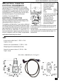
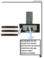
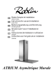
Vizio/3 Murale Verre Clean air
FR
Mode d’emploi et installation
GB
Instructions for use and installation
Hotte de Cuisine
Cooker Hood
F
SOMMAIRE
GB
CONTENTS
RACCORDEMENT ÉLECTRIQUE
ELECTRICAL WIRING
CONSEILS D’INSTALLATIONS
INS TALLATION ADVICE
POSE DE L’APPAREIL
FITTING THE APPLIANCE
FONCTIONNEMENT
OPERATION
CONSEILS D’UTILIS ATIONS
USEFUL HINTS
ENTRETIEN
MAINTENANCE
GARANTIE ET SERVICE APRÈS-VENTE
GUARANTEE AND AFTER-SALES-SERVICES
REMARQUES
REMARKS
F
Nousvousremercionsdelaconfiancequevousnousavezaccordéeenchoisissantunappareil
de la g amme ROBLIN.
Celui-ciafaitl’objetdetoutenotreattentiondanssaconceptionetsaréalisation.
Afinqu’ilvousdonneentièresatisfaction,nousvousrecommandonsdelireavecattentioncettenoticequi
vousexpliqueracommentl’installer,l’utiliseretl’entretenirdanslesmeilleuresconditions.
Laprésentenoticed’emploivautpourplusieursversionsdel’appareil.Ellepeutcontenirdesdescriptions
d’accessoiresnefigurantpasdansvotreappareil.
1
RACCORDEMENT ÉLECTRIQUE.
•
Lahotteestéquipéed’uncordond’alimentationdetypeHO5VVF3x0,75mm²comportantune
fichenormalisée10/16Aavecsystèmedemiseàlaterre.
Modedeprotection:classeI.Tensiond’alimentation:220-240Vmono-50Hz/220V-60Hz.
Vérifier que la tension du secteur est identique aux valeurs indiquées sur la plaque signalétique à
l’intérieurdelahotte
•
Silahotteestraccordéedirectementsurleréseausanssafiche,uninterrupteuromnipolaireavec
uneouverturedecontactde3mmdoitêtreinstalléavantlahotte.Lefildeterre(Jaune/vert)nedoit
pasêtreinterrompuparcetinterrupteur.
2
CONSEILS D’INSTALLATION.
•
Pourunfonctionnementidéal,nousvousconseillonsuneplagedehauteurdeposequisesituede
0,65mà0,70mau-dessusduplandecuisson.Toutefois,ilestformellement interdit d’installertoute
hotteougrouped’aspirationàunedistance inférieure à 0,65 m duplandetravail(risqued’inflammation
desfiltres).Lafuméedoitmonternaturellementverslazonedecaptation.
•
Respecterlediamètredesortiedel’appareil:la hotte ne doit en aucun cas être raccordée à un
conduitdeventilationmécaniquecontrôlée(V.M.C.).
•
Lorsqu’onévacuel’airviciédansunconduitd’évacuation,veilleràcequecelui-cinesoitpasdéjà
exploitéàvéhiculerdesgazoufuméesprovenantd’appareilsalimentésparuneénergieautrequ’électrique.
•
Positionnerleplandecuissonauplusprèsdel’évacuationetéviterlaformationdecoudessurla
gaine,afinderéduireaumaximumlespertesdecharges.
•
Danstouslescasd’installation,veilleraubonrenouvellement d’air delacuisine.Penseràeffectueruneoudesentréesd’airparunegrilledesectionégale ou supérieure au diamètre du tuyau
d’évacuation, afindenepasmettrelacuisineendépression.
•
Prévoiruneaérationsuffisantelorsqu’unappareildecuissonouautreutilisesimultanémentl’air
ambiantdelapièceoùestinstalléelahotte.
•
Ladépressionmaximumcréedanslapiècedoitêtreinférieurà0.04mbar,cequiéviteunretourde
gazdecombustion.
•
L’appareildoitêtrepositionnédetellefaçonquelafiched’alimentationsoitaccessible.
•
Cetappareilnedoitpasêtreutilisépardespersonnes(ycomprislesenfants)ayantdescapacités
psychiques, sensorielles ou mentales réduites, ni par des personnes n’ayant pas l’expérience et la
connaissancedecetyped’appareils,àmoinsd’êtresouslecontrôleetlaformationdepersonnesresponsablesdeleursécurité.
Lesenfantsdoiventêtresurveilléspours’assurerqu’ilsnejouentpasavecl’appareil.
1
F
3
POSE DE L’APPAREIL.
Montageetraccordementdoiventêtreréalisésparuninstallateur* qualifié.
(*) Le non-respect de cette condition entraîne la suppression de la garantie du constructeur et
tout recours en cas d’accident.
Attention: prendre bien soin d’employer les chevilles adaptées au support, se renseigner au près
des fabricants, effectuer un scellement si nécessaire. La société décline toute responsabilité en
cas d’accrochage défectueux dû au perçage et chevillage.
1)Tracersurlaparoiuneverticalejusqu’auplafondàl’emplacementdelahotteaucentredelazone
prévuepourlemontagedelahotte(Fig.3, rep. 1).Cettelignesertpouralignerverticalementlesdifférentesparties.
2)Positionnerlesupportdeconduit(Rep. 2),centrésurlaverticaleà40mmduplafondetmarquersur
laparoilesdeuxalésagesdusupport.EffectuersurlaparoideuxtrousavecunforetØ8mm.Fixerle
supportdeconduit(Rep. 2)etledéflecteur(R)àl’aidedesvis4.5x50etdeschevillesfournies(Fig.
4).
3)Définirlebasdelahotte(Rep 3)afindefixerlessupportsaumur(Fig 1 et 3, Rep 4).Effectuersurla
paroi4trousavecunforetØ8mm.Fixerlessupport(Rep. 4)àl’aidedesvis4.5x45etdeschevilles
fournies.
4)Montage du corps de la hotte :
Accrocherlecorps(Fig 6,Rep 5)surlessupportsmuraux(Rep. 4).
Parfaireleréglaged’alignementdel’ensemble,àl’aidedesvisTH5x25dessupports,ainsiquel’inclinaisonàl’aidedes2vis5x25mmTC.
5)Raccordement:
Raccorderélectriquementlahotte(VoirparagrapheRaccordementElectrique)etvérifierlebonfonctionnementdel’éclairage,dumoteuretduchangementdesvitessesd’aspiration.
a-Fixerlehautdeconduit(Rep. 7)ausupport(Rep. 2)par2visM4fournies.L'emplacement
delagrilledoitêtresituédevantletiroir(G)dudéflecteur(R)(Fig. 9).Puispositionnerlebasde
conduit.
b-Installeruntuyaudediamètreapproprié(Nonfourni)entrelasortiedel’appareiletàl’entréedu
déflecteur.Fixerl’ensembleàl’aidedecolliersouderubanadhésifappropriés.
c-Placerlacartouchesàcharbonactifdanssonlogementenexerçantunepressionsurleslanguettes
A(Fig. 7).
2
F
4
FONCTIONNEMENT
Tableau des commandes
Touche Fonction
A
Allume et éteint le moteur d’aspiration à la
dernière vitesse utilisée
B
Diminue la vitesse de service.
C
Augmente la vitesse de service.
D
Met en marche la vitesse intensive de
n’importe quelle vitesse, même à moteur
éteint ; cette vitesse est temporisée à 10 minutes, après quoi, le système retourne à la
vitesse réglée au préalable. Idéale pour faire
face à des émissions maximales de fumées de
cuisson.
E
Met en marche le moteur à une vitesse permettant une aspiration de 100 m3/h pendant
10 minutes toutes les heures ; après quoi le
moteur s’arrête.
F
Active l’arrêt automatique après un délai de
30’. Idéale pour éliminer complètement les
odeurs résiduelles. Peut être activée depuis
n’importe quelle position, appuyer sur la touche ou éteindre le moteur pour désactiver la
fonction.
G
Appuyer sur la touche pendant environ 2 secondes pour rétablir l’alarme signalant la
saturation des filtres à l’état initial
H
Afficheur
Affiche la vitesse réglée.
Les segments allumés diminuent.
Les segments allumés augmentent.
I clignote et les segments sur l’afficheur sont
tous allumés.
Appuyer sur la touche pour désactiver.
24 s’affiche et les segments qui sont tous allumés sur l’afficheur s’éteignent un à un de façon cyclique.
Appuyer sur la touche pour désactiver.
Le symbole d’une Horloge qui clignote
s’affiche.
Appuyer sur la touche pour désactiver.
Après 100 heures de fonctionnement, le symbole Goutte s’affiche pour signaler la saturation des filtres métalliques.
Après 200 heures de fonctionnement, C
s’affiche pour signaler la saturation des filtres
au charbon actif.
Appui court : allume et éteint l’éclairage à la dernière intensité lumineuse utilisée.
Appui long : augmente ou réduit l’intensité lumineuse.
Commande de blocage du clavier : il est possible de bloque le clavier, par exemple pour effectuer le nettoyage du verre, quand le moteur et l’éclairage de la hotte sont éteints.
Appuyer sur la touche F (Retard) pendant environ 5 secondes pour activer ou désactiver le
blocage du clavier, qui est toujours confirmé par un bip sonore et une animation sur la barre du
moteur de l’afficheur.
3
F
5
CONSEILS D’UTILISATION.
•
Pour obtenir une efficacité maximum d’absorption des fumées ou des vapeurs, faire fonctionner
l’appareil5minutesenvironavantetaprèslacuissondesaliments;Lapremièrevitesseestconseillée
pourlescuissonsàfeudouxetpourlessauces.Ladeuxièmepourlescuissonssoutenues,grilladeset
friteuses.Latroisièmeestindiquéepourlescuissonsàforteémanationdegraissesetvapeur.
•
IMPORTANT . NE JAMAIS FLAMBER DE METS AU DESSOUS DE L’APPAREIL
Nelaissezjamaisdeflammeslibressouslahotteenfonctionnement.
•
Lesfrituresnécessitentunesurveillancepermanente,l’huilesurchaufféepouvants’enflammer.
6
ENTRETIEN.
Déconnecterlecâbled’alimentationpourtouteinterventionélectrique.
L’appareilaétéconçupourfaciliteraumaximumlesopérationsd’entretien,synonymedebonfonctionnementetrendementdel’appareildansletemps.
•
Nettoyage des filtres métalliques.
IlestindispensabledeprocéderàunNETTOYAGE PÉRIODIQUE decesfiltresàlamain(avecundétergent
liquideàl’eautièdeetrinçage)ouaulave-vaisselle(touslesdeuxmoisenvironpouruneutilisationnormale).
•
Carrosserie.
Nettoyerrégulièrementcelle-cienutilisant desproduitsdétergents,nonabrasifsetuneépongelégèrement
humide.N’utilisezjamaisd’épongesoudechiffonstrempés
N’introduisezaucunobjet,nilesmainsdansl’ouvertureservantàl’évacuationdel’air
•
Filtres a charbon
Lesfiltresacharbonsnepeuventêtrenéttoyés,Ilsnécessitentunremplacementachaquetrimestreau
minimumouplussilalahotteestutiliséeplusdetroisheuresparjours.
•
Clean-air.
LeslampesUVontuneduréedevied'environ6000heuresselonl'utilisationdelahotte.
LesfiltresClean-airsuiventlecycledeviedeslampesUV.
L'échanged'unelampeUVs'accompagneautomatiquementd'unremplacementdufiltreclean-air
correspondant.
•
Éclairage.
Avanttouteinterventionsurl’appareil,mettrel’interrupteurd’allumagedeslampesenpositionéteinte.
Ne pas dépasser la puissance prescrite et ne pas changer de type de lampe.
7
GARANTIE ET SERVICE APRÈS-VENTE.
•
Encasd’anomaliedefonctionnement,prévenezvotreinstallateurquidevravérifierl’appareiletson
raccordement.
•
Danslecasoùuncomposantélectriqueviendraitàêtreendommagé,celui-cinepeutêtreremplacé
queparunatelierderéparationreconnuparlefabricant,cardesoutilsspéciauxsontnécessaires.
•
Débranchercomplètementl’appareil.
•
Exigeztoujoursl’utilisationdepiècesderechanged’origine.Lanonobservationdecetteprescription
peutcompromettrelasécuritédel’appareil.
•
Lorsdelacommandedepiècesdétachées,rappelerlenumérodel’appareilinscritsurlaplaque
signalétiquesituéeàl’intérieurdelahotte.
•
4
Seulelafactured’achatdel’appareilferafoipourl’applicationdelagarantiecontractuelle.
F
Cettegarantienecouvrepaslesconsommablescomme:
-L’éclairage:lampesincandescentes,halogènes...
-Lesfiltres.
8
REMARQUES
Cetéquipementestconformeàlanormeeuropéennesurlabassetension2006/95/CErelativeàla
sécuritéélectriqueetauxnormeseuropéennes:2004/108/CErelativeàlacompatibilitéélectromagnétiqueet93/68relativeaumarquageCE.
d’unepoubelleàrouebarréeestattachéàunproduit,celasignifiequele
Lorsquecesymbole
produitestcouvertparlaDirectiveEuropéenne2002/96/EC.Votreproduitestconçuetfabriquéavec
desmatériauxetdescomposantsdehautequalité,quipeuventêtrerecyclésetutilisésdenouveau.
Veuillezvousinformerdusystèmelocaldeséparationdesdéchetsélectriquesetélectroniques.Veuillez
agirselonlesrègleslocalesetnepasjetervosproduitsusagésaveclesdéchetsdomestiquesusuels.
Jetercorrectementvotreproduitusagéaideraàprévenirlesconséquencesnégativespotentielles
contrel’environnementetlasantéhumaine.
5
G B
ThankyouforbuyingaROBLINproductwhichhasbeenmanufacturedtothehighestqualitystandards
tomeetyourrequirements.
Werecommendyoucarefullyreadthisbookletinwhichyouwillfindinstructionsforinstallation,hintsfor
useandmaintenance.
TheInstructionsforUseapplytoseveralversionsofthisappliance.Accordingly,youmayfinddescriptionsofindividualfeaturesthatdonotapplytoyourspecificappliance.
1
ELECTRICAL
• Thiscookerhoodisfittedwitha3-coremainscablewithastandard10/16Aearthedplug.
• Alternativelythehoodcanbeconnectedtothemainssupplyviaadouble-poleswitchhaving3mm
minimumcontactgaponeachpole.
• Beforeconnectingtothemainssupplyensurethatthemainsvoltagecorrespondstothevoltageon
theratingplateinsidethecookerhood.
• TechnicalSpecification:Voltage220-240V,singlephase~50Hz/220V-60Hz.
2
INSTALLATION ADVICE
• Ensurethecookerhoodisfittedincompliancewiththerecommendedfixingheights.
• Toensurethesafeoperationofthiscookerhood,werecommendthatthehoodshouldnotbefitted
below65cm(forelectric)or(70cmforgas)themeasurementstakenfromthesurfaceofthecooking
appliancetotheundersideofthecookerhood.
• Itisapossiblefireriskifthehoodisnotsitedasrecommended.
• Toensurethebestresults,thecookingfumesshouldbeabletorisenaturallytowardstheinletgrilles
ontheundersideofthecookerhoodandthecookerhoodshouldbepositionedawayfromdoorsand
windows,whichwillcreateturbulence.
• Ducting
• Iftheroomwherethehoodistobeusedcontainsafuel-burningappliancesuchasacentralheating
boilerthenitsfluemustbeoftheroomsealedorbalancedfluetype.
• Ifothertypesofflueorappliancesarefittedensurethatthereisanadequatesupplyoffreshairto
theroom.Ensurethekitchenisfittedwithanairbrick,whichshouldhaveacross-sectionalmeasurement
equivalenttothediameteroftheductingbeingfitted,ifnotlarger.
• Theductingsystemforthiscookerhoodmustnotbeconnectedtoanyexistingventilationsystem,
whichisbeingusedforanyotherpurposesortoamechanicallycontrolledventilationducting.
• Theductingusedmustbemadefromfireretardantmaterialsandthecorrectdiametermustbeused,
asincorrectsizedductingwillaffecttheperformanceofthiscookerhood.
• Whenthecookerhoodisusedinconjunctionwithotherappliancessuppliedwithenergyotherthan
electricity, the negative pressure in the room must not exceed 0.04 mbar to prevent the fumes from
combustionbeingdrawnbackintotheroom.
• Theapplianceisfordomesticuseonlyandshouldnotbeoperatedbychildrenorpeoplewhoare
infirmwithoutsupervision.
• Thisappliancemustbepositionedsothatthewallsocketisaccessible.
• Thisapplianceisnotintendedforusebypersons(includingchildren)withreducedphysical,sensory
ormentalcapabilities,orlackofexperienceandknowledge,unlesstheyhavebeengivensupervisionor
instructionconcerninguseoftheappliancebyapersonresponsiblefortheirsafety.
Childrenshouldbesupervisedtoensurethattheydonotplaywiththeappliance.
3
FITTING
Anypermanentelectricalinstallationmustcomplywiththelatestregulationsconcerningthistypeof
installationandaqualifiedelectricianmustcarryoutthework.Non-compliancecouldcauseserious
accidentsorinjuryandwoulddeemthemanufacturersguaranteenullandvoid.
IMPORTANT - Thewiresinthismainsleadarecolouredinaccordancewiththefollowingcode:
6
G B
-green/yellow:earth-blue:neutral-brown:live
Asthecoloursofthewiresinthemainsleadofthisappliancemaynotcorrespondwiththecoloured
markingsidentifyingtheterminalsinyourplug,proceedasfollows.
-Thewirewhichiscolouredgreenandyellowmustbeconnectedtotheterminalintheplugwhichis
markedwiththeletterE orbytheearthsymbolorcolouredgreenorgreenandyellow.
-ThewirewhichiscolouredbluemustbeconnectedtotheterminalwhichismarkedwiththeletterN or
colouredblack.
-ThewirewhichiscolouredbrownmustbeconnectedtotheterminalwhichismarkedwiththeletterL or
coloured red.
ATTENTION Do not forget to use adequate plugs to the support brackets. Enquire after the manufacturers. Do an embedding if necessary. The manufacturer accepts no responsibility in case of a
faulty hanging due to the drilling and the setting up of plugs.
G B
1) Drawaverticallineontothewallfromthecentreofthecookingapplianceuptotheceilling,usinga
spiritlevelandamarkerpenasillustratedinFig. 3 - item 1.Thisistoensurethecorrectalignment
ofthechimneyhood.
2) Placethebracketsitem 2onthewallabout40mmfromtheceiling;aligningitscentreonthevertical
line.Markthetwoeyeletholesofthebracketontothewall.Drilltheholesforthefixingbracketusing
an8mmmasonrybit.Fixthechimneybracketitem 2 andtherecirculationspigot(R)usingthe4.5
x50mmscrewsandrawlplugssupplied.
3) Marktheholecentresforthecanopyfixingbracketsitem 4atitem BmmasillustratedinFig. 6.Drill
the4holesforthefixingbracketsusingan8mmmasonrybit.Fixthewallbracketsitem 4usingthe
4.5x45mmscrewsandrawlplugssupplied.
4) Hookthecanopyitem 5ontothewallbracketsitem 4asillustratedinFig. 6.Toensurethecooker
hoodisalignedcorrectlyadjustthescrewsonthetopofthecanopy.Unhookthecanopyfromthe
wallanddrilltheholeforthesecurityfixingscrew.
5)
a.FittherecirculationspigotRontotheupperchimneywallbracketusingthesamefixingscrews(Fig.
4 item 2).Thelocationofthegridmustbelocatedinfrontoftheslide(G)ofthedeflector(R).
b.Connecttheducting150mm(6INS)notprovidedbetweenmotorsitem 6andtherecirculationspigot
andsecuretheconnectionswithappropriateclampingringsoradhesivetape.
c.Beforefittingthechimneytothecanopymaketheelectricalconnectionasdescribedinthesection
titledELECTRICAL.Whentheelectricalconnectionhasbeenmade,testthelightsandthefanmotor.
d.Insertthecharcoalfilterintothebaseofthemotorhousingandsecurethefilterwithtwometalsecuringstrapsitem AasillustratedinFig. 7.
7
GB
4
OPERATION
Control panel
Button
A
B
C
D
E
F
G
H
Function
Turns the suction motor on and off at the
last speed used.
Decreases the working speed.
Increases the working speed.
Activates intensive speed from any other
speed, including motor off. This speed is
timed to run for 10 minutes, after which
the system will return to the speed that
was previously set. Suitable for dealing
with severe cooking fumes.
Starts the motor at a speed that allows a
suction of 100 m3/h for 10 minutes every
hour, after which the motor stops.
Activates automatic switch-off with a 30’
delay. Suitable to complete elimination of
residual odours. Can be activated from any
position, it is deactivated by pressing the
button of turning the motor off.
Performs a Reset of the Filter saturation
alarm when the button is pressed for approximately 2 seconds.
Short pulse : turns the Lighting System on
and off at the last intensity used
Long pulse : reduces and increases the
intensity of light.
Display
Displays the speed set.
Decreases the lighted segments.
Increases the lighted segments.
I flashes and the segments on the Display are
all lit.
It is disabled by pressing the Button.
Displays 24 and the segments on the Display,
initially all lit, turn off one at a time in cycle.
It is disabled by pressing the Button.
Displays a flashing Clock symbol.
It is disabled by pressing the Button.
After 100 hours operation the Drop symbol is
displayed to indicate saturation of the Metal
Grease Filters.
After 200 hours operation the letter C is displayed to indicate saturation of the Activated
Charcoal Filters.
Keyboard Lock Command: it is possible to lock the keyboard, for example when cleaning the
Glass, when the Hood Motor and Lights are turned off.
Press F (Delay) for approximately 5 seconds to enable or disable Keyboard Locking, which is
always confirmed by a Beep and an animated signal on the display motor bar.
8
G B
5
USEFUL HINTS
• Toobtainthebestperformancewerecommendyoutoswitch‘ON’thecookerhoodafewminutes(in
theboostsetting)beforeyoustartcookingandyoushouldleaveitrunningforapproximately15minutes
afterfinishing.
• IMPORTANT: NEVER DO FLAMBÉ COOKING UNDER THIS COOKER HOOD
• Do not leave frying pans unattended during use as over-heated fat and oil might catch fire.
• Do not leave naked flames under this cooker hood.
• Switch ‘OFF’ the electric and gas before removing pots and pans.
• Ensure heating areas on your hotplate are covered with pots and pans when using the hotplate
and cooker hood simultaneously.
6
MAINTENANCE
Beforecarryingoutanymaintenanceorcleaningisolatethecookerhoodfromthemainssupply.
Thecookerhoodmustbekeptclean;abuildupoffatorgreasemaycauseafirehazard.
Casing
• Wipethecookerhoodfrequentlywithacleancloth,whichhasbeenimmersedinwarmwatercontainingamilddetergentandwrungout.
• Neveruseexcessiveamountsofwaterwhencleaningparticularlyaroundthecontrolpanel.
• Neverusescouringpadsorabrasivecleaners.
• Alwayswearprotectivegloveswhencleaningthecookerhood.
Metal Grease Filters :Themetalgreasefiltersabsorbgreaseanddustduringcookinginordertokeep
cleanthecookerhoodinside.Thegreasefiltersshouldbecleanedonceamonthormorefrequentlyif
thehoodisusedformorethan3hoursperday.
To remove and replace the metal grease filters
• Removethemetalgreasefiltersoneatatimebyreleasingthecatchesonthefilters;thefilterscan
nowberemoved.
• Themetalgreasefiltersshouldbewashed,byhand,inmildsoapywaterorinadishwasher.
• Allowtodrybeforereplacing.
Active Charcoal Filter : Thecharcoalfiltercannotbecleaned.Thefiltershouldbereplacedatleast
everythreemonthsormorefrequentlyifthehoodisusedformorethanthreehoursperday.
To remove and replace the filter
• Removethemetalgreasefilters.
• Pressagainstthetworetainingclips,whichholdthecharcoalfilterinplaceandthiswillallowthefilter
todropdownandberemoved.
• Cleanthesurroundingareaandmetalgreasefiltersasdirectedabove.
• Insertthereplacementfilterandensurethetworetainingclipsarecorrectlylocated.
• Replacethemetalgreasefilters.
Clean air.
UVlampshavealifeofabout6000hoursdependingonusageofthehood.
Clean-airfiltersfollowingthelifecycleofUVlamps.
Changethefiltersclean-airatthesametimeastheUVlamps.
Lighting :Ifthelampfailstofunctionchecktoensureitisfittedcorrectlyintotheholder.Iflampfailure
hasoccurredthenitshouldbereplacedwithidenticalreplacement.
Do not replace with any other type of lamp and do not fit a lamp with a higher rating.
9
G B
7
GUARANTEE AND AFTER SALES SERVICE
• In the event of any malfunction or anomaly, notify your fitter who will have to check the appliance and its connection.
• Intheeventofdamagetothemainssupplycable,thiscanonlybereplacedbyatapprovedrepair
centreappointedbythemanufacturerwhowillhavetherequiredtoolsandequipmenttocarryoutany
repairsproperly.Repairscarriedoutbyotherpersonswillinvalidatetheguarantee.
• Useonlygenuinespareparts.Shouldthesewarningsfailtobeobserveditcouldaffectthesafetyof
yourcookerhood.
• Whenorderingsparepartsquotethemodelnumberandserialnumberwrittenontheratingplate,
whichisfoundonthecasingbehindthegreasefiltersinsidethehood.
• Proof of purchase will be required when requesting service. Therefore, please have your receipt
availablewhenrequestingserviceasthisconstitutesthedatefromwhichyourguaranteecommenced.
ThisGuaranteedoesnotcover:
- Damageorcallsresultingfromtransportation,improperuseorneglect,thereplacementofanylight
bulbsorfiltersorremovablepartsofglassorplastic.
Theseitemsareconsideredtobeconsumableunderthetermsofthisguarantee.
8
REMARKS
ThisappliancecomplieswithEuropeanregulationsonlowvoltagesDirective2006/95/CEonelectrical
safety,andwiththefollowingEuropeanregulations:Directive2004/108/CEonelectromagneticcompatibilityandDirective93/68onECmarking.
Whenthiscrossed-outwheeledbinsymbol
isattachedtoaproductitmeanstheproductiscoveredbytheEuropeandirective2002/96/EC.Yourproductisdesignedandmanufacturedwithhighquality
materialsandcomponents,whichcanberecycledandreused.
Pleaseinformyourselfaboutthelocalseparatecollectionsystemforelectricalandelectronicproduct.
Pleaseactaccordingtoyourlocalrulesanddonotdisposeofyouroldproductswithyournormalhouseholdwaste.Thecorrectdisposalofyouroldproductwillhelppreventpotentialnegativeconsequences
fortheenvironmentandhumanhealth.
10
SCHEMA ELECTRIQUE
ECLAIRAGE
LIGHTING
BELEUCHTUNG
2 X LEDS 5 W
Red
Purple
Black
Purple
PWM
+ -
J7
J3
J4
Pink
Blue
Brown
Black
J6
1 2 3
4 5 6
7 8 9
J1
J-Y
J13
J2
J11
PWM
Red
Blue
B
J-Y
R
MULTI-FLACHKABEL
LIMANDE COMMANDE
FLATCABLE
J-Y
ELEKTRONISCHE STEUERUNG
BOITIER COMMANDE
PUSCH BUTTON PANEL
B
J-Y
R
B
J-Y
R
6.3 µF
425 V
1 2 3
4 5 6
7 8 9
UV lamps
3 x 20 W
Brown
Yellow
Pink
White
Blue
Black
Grey
B
J-Y
R
B
J-Y
R
B
J-Y
R
Light-Blue
Brown
Green-Yellow
M
250 W
220 - 240 V
A1
A - AZUR - AZUR - AZUR BLAU
BK - BLACK - NOIR- SCHWARZ
B - BLUE - BLEU - BLAU
Br - BROWN - BRUN - BRAUN
G-Y - GREEN YELLOW - VERT JAUNE - GRÜN GELB
Gr - GREY - GRIS - GRAU
L B - LIGHT BLUE - BLEU CLAIR - HELL BLAU
P - PINK - ROSE - ROSA
V - PURPLE - MAUVE - MALVER FARBIG
R - RED - ROUGE - ROT
W - WHITE - BLANC - WEISS
W-P - WHITE PINK - BLANC ROSE - WEISS ROSA
Y - YELLOW - JAUNE - GELB
Green-Yellow
50Hz
RACCORDEMENT ELECTRIQUE
UK ELECTRICAL CONNECTION
The wires in this mains
lead are coloured in
accordance with the
following code:
ELECTRICAL REQUIREMENTS
Any permanent electrical installation must comply
with the latest I.E.E. Regulations and local Electricity
Board regulations. For your own safety this should be
undertaken by a qualified electrician e.g. your local
Electricity Board, or a contractor who is on the roll of
the National Inspection Council for Electrical
Installation Contracting (NICEIC).
ELECTRICAL CONNECTION
Before connecting to the mains supply ensure that
the mains voltage corresponds to the voltage on the
rating plate inside the cooker hood.
This appliance is fitted with a 2 core mains cable and
must be permanently connected to the electricity supply
via a double-pole switch having 3mm minimum contact
gap on each pole. A Switched Fuse Connection Unit
to BS.1363 Part 4, fitted with a 3 Amp fuse, is a
recommended mains supply connection accessory to
ensure compliance with the Safety Requirements
applicable to fixed wiring instructions.
Green & Yellow
Earth
Blue
Neutral
Brown
Live
As the colours of the wires
in the mains lead of this
appliance may not
correspond with the
coloured markings
identifying the terminals in
your connection unit,
proceed as follows:The wire which is coloured blue must be connected
to the terminal which is marked with the letter ‘N’ or
coloured black.
The wire which is coloured brown must be connected
to the terminal which is marked with the letter ‘L’ or
coloured red.
CH
Fiche de sécurité class 1, 250 V~ 10A
2 poles + terre.
Stecker der Schutzklasse 1, 250 V~ 10A
Zweipolig mit Schutzkontakt (Erde).
Spira di sicurezza classe 1, 250 V~ 10A
2 poli + terra
SEV 1011, SN416534-2, CH-Typ 12
A2
OPTION
Crédence
Splachback
Rückwand
Fondale
Panel
409
Spatscherm
A
848/
8 1048
27
405
175
8
8
175
8
898/
8 1098
12
A
A4
A3
COMPOSANTS
2
7
R
5
4
9
8
Vizio/3 Murale Verre Clean air
6
Mode d’emploi et installation
FR
Hotte de Cuisine
GB
Cooker Hood
Instructions for use and installation
45
A4
ACCESSOIRES
8
LR03 / AAA / 1,5V
1
FILTRE CHARBON
A5
FILTRE METALLIQUE
DIMENSIONS
857
35
359
150
898 / 1098
44
152
473
752
438
mini.1194 -maxi.1473
475
26
47
285
190
400
41
45°
6
40
A
MONTAGE
1
R
2
7
5
4
258.5
69.4
2
30
30
535
200
A7
MONTAGE
670
82
3
40
2
293
4
A8
MONTAGE
6
4
5
A = 1070 mm
B = 260 mm
7
A
A9
RECYCLAGE
A10
FILTRE
G
FILTRE CHARBON
A1
ECLAIRAGE
2
LEDS 2 x 7 W
1
2
2
1
1
A12
ECLAIRAGE
LEDS 2 x 7 W
A
IDENTIFICATION
Plaque Signalétique de la hotte
Rating plate of the cookerhood
Typenschild im Innen der Dunstessere
Etichetta all'interno della cappa
Etiqueta de la campana
Typeplaatje van de afzuigkap
A14
FRANKE France S.A.S.
25 Rue des Rosiers - Sainte Cécile
B. P. 60056
50800 VILLEDIEU-LES-POËLES - France
Tél. 02 33 91 26 50 - Fax 02 33 51 54 79 - e-mail : [email protected]
For outside France : Tel. +33 (0)2 33 91 26 57 - Fax. : +33 (0)2 33 51 54 79
e-mail : [email protected]
991.0324.502 - 140425