1
05-340 / 05-341
Read the complete manual before attempting installation and activating the system.
1. DESCRIPTION
This RF receiver is part of the Niko RF (Radio Frequency) system, an installation technique that does not require
any wiring between the control points (push buttons) and the consumers to be operated. This technique is known
as remote control or wireless control. Transmission occurs by means of radio waves at the 868,3MHz frequency.
This frequency is reserved for products that do not transmit continuously (max.1% per hour = 36s.), so that
there is only a minimal risk of interference. The system is therefore ideally suitable for use in specific applications
such as renovation of interiors, extensions in existing electrical installations where drilling or channeling work
is excluded, offices with movable walls… or to avoid the use of complex cabling configurations. It is a modular
system built around transmitters and receivers. The wall-mount transmitters take the form of an ordinary switch
suited for wall mounting. The hand-held transmitters take the form of a conventional remote control unit. Each
transmitter can control an unlimited number of receivers simultaneously. Each receiver can be controlled by up
to 32 transmitters. These products conform to the EU regulations and comply with the essential requirements of
the R&TTE directive: 1999/5/EC. The certificate of conformity can be obtained from the Niko support service.
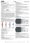
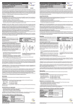
LED Programming mode
05-340:
Intermediate receiver plug with earthing pin for Easywave wall mounted transmitter
LED Programming mode
05-341:
Intermediate receiver plug with safety
earth for Easywave wall mounted transmitter
2. OPERATION AND USE
2.1. Range between Easywave transmitters and receivers
Equipment using a remote control, such as tv, video and audio, does not suffer interference from the Easywave
transmitters. The Easywave transmitters need not be pointed at the receiver. The range in buildings amounts
to ±30m. In open fields, ranges of up to 100m are possible. The transmitter range depends on the materials
used in the building.
You can use diagnosis unit 05-370 to determine the RF signal strength in a given environment. The device detects
all 868,3MHz signals. The reception quality of the transmitter signal or the strength of the interfering signals
present is indicated by 9 LEDs, allowing you to determine whether the RF transmitter’s range is sufficient.
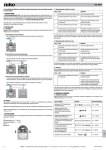
brick, concrete
loss: 20 to 40% wood, plaster walls
loss: 5 to 20%
reinforced concrete
loss: 40 to 90%
enclosure in metal
loss: 90 to 100%
2.2. Installation instructions and recommendations
NEVER install the transmitters:
- in a metal distribution box, housing or metal netting;
- in the immediate vicinity of large metal objects;
- on (or near) the floor.
Install the receivers as close to the transmitters as possible. The presence of metal or moisture in the walls can
have a negative influence on the transmitter range.
3. PROGRAMMING
3.1. Putting into service
After installing the transmitters and receivers, the transmitters must be programmed with the receivers. A receiver
only functions if the address of a transmitter has been programmed in the receiver.
Test the transmitter before installing it!
3.2. Programming
-Apply 1 brief (< 1,6s.) press to the ‘program’ button.
-LED starts blinking (light signal mode 1).
-If you want to switch to another mode, briefly (< 1,6s.) press on the program button repeatedly. A light signal
starts blinking (see mode setting).
Mode setting
Mode
Models
M1
2-keys
M2
1-key
M3
1-key
Where to
operate?
top
bottom
Operate for how
long?
>1,5s.
Function
on
off
on/off/on/off
off
on
Operating
time
no limit
no limit
no limit
no limit
7'
Light signal during
programming
-Program all transmitters that have to work with the receiver one by one. The correct reception of an address
is confirmed by a long light signal (4s.).
-Up to 32 transmitters can be programmed per receiver. When this maximum is reached the LED will keep
blinking.
-Briefly (< 1,6s.) press on the program button repeatedly to end programming (Mode1 - mode2 - mode3 - off).
The programming is not lost in the event of a prolonged power failure.
3.3. Adding transmitters
You can program additional transmitters (max. 32) on a receiver at all times. Therefore, repeat ‘4.2. Programming’.
3.4. Reset
-Press the flush key on the receiver (see '3.2. Programming') for more than 1,6s. (blinking LED).
-Press again for more than 1,6s.
-The receiver’s memory is now completely erased. This is acknowledged by a long light signal (4s.).
-End RESET by briefly pressing the flush key (< 1,6s.).
nv Niko sa
3.5. Erasing selectively
-Press the flush key on the receiver for more than 1,6s.
-A light signal starts blinking (blinking LED).
-Press 1 of the control buttons of the transmitter you want to erase.
-The transmitter is erased from the memory, which is confirmed by a long light signal (4s.).
-End RESET by briefly (<1,6s.) pressing the flush key again.
4. TROUBLESHOOTING
If, after programming, the system does not work, you can perform a number of extra checks.
4.1 New installation
-Check whether the protection between the battery and the contacts in the transmitter has been removed.
-Check whether the battery and the contacts make good permanent contact.
-Reset and (re)program the receiver.
-Press the programming key. The receiver is now in programming mode. The LED blinks and the load is activated.
If this is not the case, the receiver is defective.
-Program the transmitters with the receiver and end programming.
4.2. Existing installation
-Check the batteries of the transmitter(s).
-Check the operation of the connected receivers.
-Check for possible interference caused by changes in the system environment (moving of metal cabinets, walls
or furniture...). Restore the original condition, if possible.
4.3. Transmitter malfunction
Pick up the transmitter and walk towards the receiver.
-The system still works when holding the transmitter in your hand but not when the transmitter is mounted on
the wall: this may indicate the presence of moist or metal in the wall. In this case, move the transmitter.
-The system still works at reduced distance: the transmitter has been placed outside the transmitter range
or there is an interference problem. In this case, place the transmitter closer to the receiver or outside the
interference reach.
-The system does not work even when holding the transmitter close to the receiver: check the programming
and/or the battery of the transmitter (see above).
4.4. The system automatically switches on and off
-The system automatically switches on: this is only possible if a foreign transmitter was programmed in the receiver
within the receiver range. Reset the receiver and reprogram the relevant addresses (see ‘3.2. Programming’).
-The system automatically switches off: this situation can be similar to the situation described above or be the
result of brief current interruptions.
5. TECHNICAL DATA
-transmitter range: 100m in open air; ±30m indoors
-no wiring between control points and receivers (RF controlled), only one connection between the switch-receiver
and the device to be operated.
-receiver and transmitter form one integrated whole
-operating temperature: -5 to 45°C
-1-channel receiver: 1 relay 10A, 230V 50Hz. Only suitable for mono-phase configurations. The contact cannot
be used for SELV-circuits.
LOAD TABLE
Load type Max. load 230V 50Hz*
Resistive:
10A (40 000x)
incandescent lamps, halogen 230V~…
8A (>40 000x)2 300W
Inductive: low-voltage lighting via ferromagnetic
transformers (transformer loaded for at least 85%)
2,6A
600VA
Non- or series-compensated fluorescent lamps
with ferromagnetic ballasts
10A
2 300VA
Parallel-compensated fluorescent lamps
with ferromagnetic ballasts
2,6A
600W
Electronic control gear
(HF-fluorescence ballasts, electronic transformers…)
4A
920VA
*Max. load with integrated relay: the power can always be extended, also on different phases, with external
relays
6. LEGAL WARNINGS
-The installation has to be carried out by a qualified person and in compliance with the statutory regulations.
-This user manual has to be handed over to the user. It has to be included in the electrical installation file and
has to be passed on to any new owners. Additional copies are available on the Niko website or via the support
service.
-During installation, the following has to be taken into account (not limited to list below):
-The statutory laws, standards and regulations;
-The state of the art technique at the moment of installation;
-This user manual, which must be read within the scope of each specific installation, only states general
regulations;
-The rules of proper workmanship
-In case of questions, you can consult Niko’s support service or contact a registered control organisation.
Support Belgium:
Support UK:
+32 3 778 90 80
+44 1525877707
website : http://www.niko.be
http://www.nikouk.com
e-mail: [email protected]
[email protected]
In case of a defect, you can return your product to a registered Niko wholesaler, together with a clear description
of your complaint (Conditions of use, stated defect…).
7. GUARANTEE PROVISIONS
-Period of guarantee: 2 years from date of delivery. The delivery date is the invoice date of purchase of the
product by the consumer. If there is no invoice, the date of production applies.
-The consumer is obliged to inform Niko in writing about the defect, within two months after stating the
defect.
-In case of a failure to conform, the consumer has the right to a repair or replacement (decided by Niko) free
of charge.
-Niko cannot be held liable for a defect or damage as a result of an incorrect installation, improper or careless
use or wrong usage or transformation of the goods.
-The compulsory regulations of the national legislation concerning the sales of consumer goods and the protection
of the consumers in the countries where Niko sells, directly or via sister or daughter companies, chain stores,
distributors, agents or permanent sales representatives, take priority over the rules and regulations mentioned
above.
Industriepark West 40, BE-9100 Sint-Niklaas, Belgium — tel. +32 3 778 90 00 — fax +32 3 777 71 20 — e-mail: [email protected] — www.niko.be
PM005-34000R08152