1
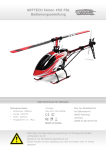
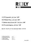
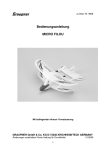
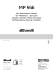
zu Best.-Nr. 9584
Anleitung
BAE HAWK
Mit Elektroimpellerantrieb,
für 5 LiPo-Zellen 4800 mAh oder
für 6 LiPo-Zellen 4800 mAh
Es wird eine Fernsteuerung mit mindestens 3 Funktionen benötigt
GRAUPNER GmbH & Co. KG D-73230 KIRCHHEIM/TECK GERMANY
Keine Haftung für Druckfehler. Technische Änderungen vorbehalten!
1
10/2008
Technische Daten
Spannweite ca.
1365 mm
Rumpflänge ca.
1465 mm
Fluggewicht je nach Akku ca.
2480 g
Impeller
Ø 92 mm
Schwerpunkt : 127 mm hinter der geraden Kante des Tragflügels (Nasenleiste) siehe
Seite 21
Das Modell ist vorgefertigt,. Impeller liegt dem Baukasten bei, es sind keine
Spezialwerkzeuge erforderlich, lediglich der Rumpf und die Tragflügel müssen verklebt
werden. Zum Betrieb wird eine Fernsteuerung mit 4 Funktionen benötigt, Empfänger ,
Motor, Flugakku und Einziehfahrwerk sind im Bausatz nicht enthalten!
Das Modell erfordert gute Flugkenntnisse voraus,
Sicherheitshinweise
Vor dem Versuch der ersten Inbetriebnahme muss die gesamte Betriebs- und
Montageanleitung sorgfältig gelesen werden. Sie alleine sind verantwortlich für den
sicheren Betrieb Ihres RC-Flugmodells. Das Modell ist geeignet für Personen ab 16
Jahre, bei Personen unter 18 Jahren muss der Bau und Betrieb von einem
Erwachsenen, der mit den Gegebenheiten und möglichen Gefahren eines RCFlugmodells vertraut ist, verantwortlich überwacht werden.
Diese Bedienungsanleitung muss sorgfältig aufbewahrt und im Falle einer
Weitergabe dem nachfolgenden Benutzer unbedingt mit ausgehändigt werden.
Fragen, bezüglich der Sicherheit beim Betrieb des RC-Flugmodells, werden Ihnen
vom Fachhandel gerne beantwortet.
Achten Sie beim Kauf einer Funkfernsteuerung darauf, dass die Sende- und
Empfangsgeräte auch für Flugmodelle geeignet und bei der Deutschen
Bundespost-Telekom zugelassen sind, sowie eine FTZ-Serienprüfnummer besitzen.
In den Frequenzbereichen für Funkfernsteuerungen werden auch andere
Funkanlagen und Hochfrequenzgeräte betrieben. Deshalb kann kein Schutz vor
Störungen durch solche Geräte gewährt werden.
Weitere Informationen zu diesem Thema bekommen Sie bei Ihrer örtlichen TelekomNiederlassung oder bei Ihrem Modellbau-Fachhändler
Fernsteuer-Flugmodelle sind sehr anspruchsvolle und gefährliche Gegenstände
und erfordern vom Betreiber einen hohen Sachverstand, Können und
Verantwortungsbewusstsein.
Rechtlich gesehen, ist ein Flugmodell ein Luftfahrzeug und unterliegt
entsprechenden Gesetzen, die unbedingt eingehalten werden müssen. Die
Broschüre »Modellflugrecht, Paragrafen und mehr«, Best.-Nr. 8034.02, stellt eine
Zusammenfassung dieser Gesetze dar; sie kann auch beim Fachhandel
eingesehen werden. Ferner müssen postalische Auflagen, die die Fernlenkanlage
betreffen, beachtet werden. Entsprechende Hinweise finden Sie in der
Bedienungsanleitung Ihrer Fernsteueranlage.
Es dürfen nur die im Bausatz enthaltenen Teile, sowie die ausdrücklich von uns
empfohlenen Original-Graupner-Zubehör- und Ersatzteile verwendet werden.
GRAUPNER GmbH & Co. KG D-73230 KIRCHHEIM/TECK GERMANY
Keine Haftung für Druckfehler. Technische Änderungen vorbehalten!
2
10/2008
Wird auch nur eine Komponente der Antriebseinheit geändert, ist ein sicherer
Betrieb nicht mehr gewährleistet und es erlischt jeglicher etwaiger
Garantieanspruch.
Verwenden Sie immer nur passende, verpolungssichere Steckverbindungen. Alle
stromführenden Leitungen, Steckverbindungen, sowie die Antriebsbatterie, bei
Selbstkonfektionierung, kurzschlusssicher isolieren. Kombinieren Sie niemals
unterschiedliche, z. B. Blech- und Goldkontakte, da hier keine sichere Funktion
gewährleistet ist.
Bei Verwendung von Schaltern bzw. Reglern mit Empfängerstromversorgung nur
Steckverbindungen mit Graupner-Gold-Kontakten verwenden.
Kurzschlüsse und Falschpolungen vermeiden.
Durch die hohe Energie der LiPo-Batterien besteht Explosions- und Brandgefahr.
Ein RC-Flugmodell kann nur funktionsfähig sein und den Erwartungen
entsprechen, wenn es im Sinne der Bauanleitung sorgfältigst gebaut wurde. Nur
ein vorsichtiger und überlegter Umgang beim Betrieb schützt vor Personen- und
Sachschäden. Niemand würde sich in ein Flugzeug setzen und - ohne
vorausgegangene Schulung - versuchen, damit zu fliegen. Auch Modellfliegen
bedarf einer fundierten Schulung.
Der Hersteller hat jedoch keine Möglichkeit, den Bau und den Betrieb eines RCFlugmodells zu beeinflussen. Deshalb wird hiermit auf die Gefahren
nachdrücklich hingewiesen und jede Haftung dafür abgelehnt.
Bitte wenden Sie sich dazu an erfahrene Modellflieger, an Vereine oder
Modellflugschulen. Ferner sei auf den Fachhandel und die einschlägige Fachpresse
verwiesen. Am besten als Club-Mitglied auf zugelassenem Modellflugplatz fliegen.
Sie alleine sind verantwortlich für den sicheren Betrieb Ihres RC-Flugmodells.
Fragen, die die Sicherheit beim Betrieb des RC-Flugmodells betreffen, werden
Ihnen vom Fachhandel gerne beantwortet.
Klebstoffe und Lacke enthalten Lösungsmittel, die unter Umständen
gesundheitsschädlich sein können. Beachten Sie daher unbedingt auch die
entsprechenden Hinweise und Warnungen der Hersteller.
Der Betreiber muss im Besitz seiner vollen körperlichen und geistigen Fähigkeiten
sein. Wie beim Autofahren, ist der Betrieb des Flugmodells unter Alkohol oder
Drogeneinwirkung nicht erlaubt.
Informieren Sie alle Passanten und Zuschauer vor der Inbetriebnahme über alle
möglichen Gefahren, die von Ihrem Modell ausgehen und ermahnen diese, sich in
ausreichendem Schutzabstand, wenigstens 5 m hinter der Luftschraubenebene,
aufzuhalten.
Stets mit dem notwendigen Sicherheitsabstand zu Personen oder Gegenständen
fliegen; nie Personen in niedriger Höhe überfliegen oder auf sie zufliegen!
Modellflug darf nur bei Außentemperaturen von - 5º C bis + 35º C betrieben werden.
Extremere Temperaturen können zu Veränderungen von z. B. Akkukapazität,
Werkstoffeigenschaften und mangelhafte Klebeverbindungen führen.
Jeder Modellflieger hat sich so zu verhalten, dass die öffentliche Sicherheit und
Ordnung, insbesondere andere Personen und Sachen, sowie die Ordnung des
GRAUPNER GmbH & Co. KG D-73230 KIRCHHEIM/TECK GERMANY
Keine Haftung für Druckfehler. Technische Änderungen vorbehalten!
3
10/2008
Modellflugbetriebs nicht gefährdet oder gestört wird.
Das Flugmodell niemals in der Nähe von Hochspannungsleitungen,
Industriegelände, in Wohngebieten, öffentlichen Straßen, Plätzen, Schulhöfen,
Parks und Spielplätzen usw. fliegen lassen.
Warnungen müssen unbedingt beachtet werden. Sie beziehen sich auf Dinge und
Vorgänge, die bei einer Nichtbeachtung zu schweren - in Extremfällen tödlichen
Verletzungen oder bleibenden Schäden führen können.
Luftschrauben und generell alle sich drehenden Teile, die durch einen Motor
angetrieben werden, stellen eine ständige Verletzungsgefahr dar. Sie dürfen mit
keinem Körperteil berührt werden! Eine schnell drehende Luftschraube kann z. B.
einen Finger abschlagen!
Sich niemals in oder vor der Drehebene von Luftschrauben aufhalten! Es könnte
sich doch einmal ein Teil davon lösen und mit hoher Geschwindigkeit und viel
Energie wegfliegen und Sie oder Dritte treffen. Darauf achten, dass kein sonstiger
Gegenstand mit einer laufenden Luftschraube in Berührung kommt!
Die Blockierung der Luftschraube, durch irgendwelche Teile, muss ausgeschlossen
sein.
Vorsicht bei losen Kleidungsstücken wie Schals, weiten Hemden usw.: sie werden
vom Propellerstrahl angesaugt und können in den Luftschraubenkreis gelangen.
Überprüfen Sie vor jeder Inbetriebnahme das Modell und alle an ihm gekoppelten
Teile (z. B. Luftschrauben, Getriebe, RC-Teile usw.) auf festen Sitz und mögliche
Beschädigungen. Das Modell darf erst nach Beseitigung aller Mängel in Betrieb
genommen werden.
Auf gute Standfestigkeit achten, wenn Sie das Modell in der Hand halten.
Passendes Schuhwerk, z. B. Sportschuhe, tragen.
Vergewissern Sie sich, dass die verwendete Frequenz frei ist. Erst dann
einschalten! Funkstörungen, verursacht durch Unbekannte, können stets ohne
Vorwarnung auftreten! Das Modell ist dann steuerlos und unberechenbar!
Fernlenkanlage nicht unbeaufsichtigt lassen, um ein Betätigen durch Dritte zu
verhindern.
Elektromotor nur einschalten, wenn nichts im Drehbereich der Luftschraube ist.
Nicht versuchen, die laufende Luftschraube anzuhalten. Elektromotor mit
Luftschraube nur im fest eingebauten Zustand laufen lassen.
Die Fluglage des Modells muss während des gesamten Fluges immer eindeutig
erkennbar sein, um immer ein sicheres Steuern und Ausweichen zu gewährleisten.
Machen sich während des Fluges Funktionsbeeinträchtigungen /Störungen
bemerkbar, muss aus Sicherheitsgründen sofort die Landung eingeleitet werden.
Sie haben anderen Luftfahrzeugen stets auszuweichen. Start- und Landeflächen
müssen frei von Personen und sonstigen Hindernissen sein.
GRAUPNER GmbH & Co. KG D-73230 KIRCHHEIM/TECK GERMANY
Keine Haftung für Druckfehler. Technische Änderungen vorbehalten!
4
10/2008
Immer auf vollgeladene Akkus achten, da sonst keine einwandfreie Funktion der
RC-Anlage gewährleistet ist.
Niemals heiß gewordene, defekte oder beschädigte Batterien verwenden. Es sind
stets die Gebrauchsvorschriften des Batterieherstellers zu beachten.
Vor jedem Flug eine Überprüfung der kompletten RC-Anlage, sowie des
Flugmodells auf volle Funktionstüchtigkeit und Reichweite durchführen.
Dabei ist zu beachten, dass bei der Inbetriebnahme die Motorsteuerfunktion am
Sender immer zuerst in AUS-Stellung gebracht wird. Danach Sender und dann erst
Empfangsanlage einschalten, um ein unkontrolliertes Anlaufen des Elektromotors
zu vermeiden. Gleichfalls gilt immer zuerst Empfangsanlage ausschalten, danach
erst den Sender.
Überprüfen Sie, dass die Ruder sich entsprechend der Steuerknüppel-Betätigung
bewegen.
Für den Betrieb des Modells wird eine gültige Haftpflichtversicherung benötigt.
Mit diesen Hinweisen soll auf die vielfältigen Gefahren hingewiesen werden, die
durch unsachgemäße und verantwortungslose Handhabung entstehen können.
Richtig und gewissenhaft betrieben ist Modellflug eine kreative, lehrreiche und
erholsame Freizeitgestaltung.
Empfohlenes Zubehör
Fernsteuerung
Ab MX – 12S, 35- MHZ- Band, Best.-Nr. 4745
6 Servo (mit Einziehfahrwerk) DS 271 Best.-Nr. 5107
Regler COMPACT CONTROL 75S Best.-Nr. 7207
Einweg-Absperrventil Best.-Nr. 5171
2 Verlängerungskabel Best.-Nr. 3935.75
2 Verlängerungskabel Best.-Nr. 3935.50
2 Verlängerungskabel Best.-Nr. 3935.32
1 Verlängerungskabel Best.-Nr. 3935.18
Empfänger
SMC- 14, Best.-Nr. 7033
es ist empfehlenswert, in jedem Fall einen SPCM-Empfänger zu verwenden!
Antriebsbatterie
Lipo 5/4800 18,5V/4800, Best.-Nr. 7659.5 oder
Lipo 6/4800 22,2V/4800, Best.-Nr. 7658.6.3
Fahrwerk
Pneumatisches Dreibein-Einziehfahrwerk Best.- Nr. 183
Klebstoff
Devcon- 5 Minuten- Epoxykleber, Best.-Nr. 961.70
oder vergleichbare Epoxydharz- Schnellklebstoffe
UHU por Best.-Nr. 959
UHU schraubensicher Best.-.Nr. 952
Erforderliches Material und Werkzeug
Messer Best.-Nr.14.2
GRAUPNER GmbH & Co. KG D-73230 KIRCHHEIM/TECK GERMANY
Keine Haftung für Druckfehler. Technische Änderungen vorbehalten!
5
10/2008
Bauanleitung
Vor dem Zusammenkleben der Teile die Servos mit Servotester oder Fernsteuerung.
auf Funktion überprüfen Der abgewinkelte Stahldraht wird mit Epoxykleber in die
vorhandene Nut bis zum Grund und die Füllstücke mit dem Leitwerk bündig eingeklebt.
Nach dem Trocknen, die Lagerböcke re. und li.(Kunststoffteile) mit Stellringe
aufschieben, entsprechend Luft geben, dass die Ruder nicht am Rumpf streifen und die
Gewindestifte mit UHU schraubensicher festdrehen.
Fahrwerksbefestigungen mit Holzleim verleimen, nach dem Trocknen mit Epoxykleber in
die Tragflächen einkleben.
Die
GRAUPNER GmbH & Co. KG D-73230 KIRCHHEIM/TECK GERMANY
Keine Haftung für Druckfehler. Technische Änderungen vorbehalten!
6
10/2008
Befestigungslaschen an den Querruderservo werden entfernt, großer Servohebel
rechtwinklig zum Servo befestigt(Servo muss auf neutral stehen), Kabelverlängerung
500 mm anstecken und gegen Lösen sichern mit Sekundenkleber oder Steckverbindung
mit Schrumpfschlauch einschrumpfen. Servo in Aussparung einlegen, anzeichnen wo
Kabel verläuft und die entsprechenden Stege mit heißem Lötkolben ausschmelzen.
Servogehäuse anschleifen und mit Epoxykleber in die dafür vorgesehene Öffnung
kleben. Tragflügelunterteil mit UHU por aufkleben. Beim Einbau des Einziehfahrwerks
wird der Druckluftschlauch in die dafür vorgesehene Nut vorher verlegt.
Die Tragflügelhälften mit Epoxykleber profilbündig verklebt.
GRAUPNER GmbH & Co. KG D-73230 KIRCHHEIM/TECK GERMANY
Keine Haftung für Druckfehler. Technische Änderungen vorbehalten!
7
10/2008
Die Flächenverbinder mit Holzleim verleimen, nach dem Trocknen werden die
Verbinder, Verstärkungen und Befestigung mit Epoxy flächenbündig eingeklebt.
Das Hauptfahrwerk nach den Bildern zusammenbauen und die Schrauben gegen Lösen
mit UHU schraubensicher sichern.
An Fahrwerkzylinder, Druckluftschlauch anbringen, Fahrwerk in Aufnahme stecken,
entsprechend vorbohren und einschrauben. Druckluftschlauch mit UHU por in Nut
kleben. Die Enden von dem Druckluftschlauch in ein Y-Steckverbinder oder TVerbindungsstück zusammenführen.
GRAUPNER GmbH & Co. KG D-73230 KIRCHHEIM/TECK GERMANY
Keine Haftung für Druckfehler. Technische Änderungen vorbehalten!
8
10/2008
Für Ruderhorn an entsprechender Stelle mit Balsamesser einen Schlitz einschneiden,
Ruderhorn einstecken, Gegenplatte von anderer Seite aufstecken, Überstand
abschneiden und mit Sekundenkleber festkleben(nur Kunststoff-Kunststoff).
Vorsicht: dass kein Kleber auf das Styropor kommt!
Gestängeanschluss auf Servohebel schrauben, Gestänge in Ruderhorn einhängen,
Gestänge durch Gestängeanschluss führen, Servo und Ruder auf Neutralstellung
stellen, Gewindestift mit UHU schraubensicher festziehen und den restlichen Stahldraht
abzwicken.
GRAUPNER GmbH & Co. KG D-73230 KIRCHHEIM/TECK GERMANY
Keine Haftung für Druckfehler. Technische Änderungen vorbehalten!
9
10/2008
Servo von Höhenleitwerk anrauen (mit Schleifpapier), auf Neutral stellen, großer
Servohebel aufschrauben, Verlängerungskabel 750 mm anschließen, gegen Lösen
sichern und in die dazugehörige Öffnung mit Epoxykleber in jede Rumpfhälfte einkleben.
In den Rumpfschalen die Kabel von den Servos anzeichnen und mit Lötkolben Kanal
herausschmelzen.
Impeller mit Motor entsprechend Foto zusammenbauen
GRAUPNER GmbH & Co. KG D-73230 KIRCHHEIM/TECK GERMANY
Keine Haftung für Druckfehler. Technische Änderungen vorbehalten!
10
10/2008
Schubrohr bis an die Kante (Richtung Impeller) mit UHU por in eine Rumpfhälfte
einkleben, darauf achten, dass die kleine Öffnung hinten Auslass und die große Einlass
(Richtung Impeller) ist.
Montageholz für Impeller mit Holzleim verleimen, nach dem Trocknen mit Epoxykleber
an entsprechender Stelle einkleben.
Hintere Rumpfteile an vordere Rumpfteile mit UHU por verkleben
GRAUPNER GmbH & Co. KG D-73230 KIRCHHEIM/TECK GERMANY
Keine Haftung für Druckfehler. Technische Änderungen vorbehalten!
11
10/2008
Impeller in die vorgesehene Öffnung legen, anzeichnen wo die Anschlüsse vom Motor
zum Regler gehen und entsprechend Schubrohr ausschneiden. An Regler Buchsen für
Inlinemotor anlöten, Kabel für Akku verlängern und entsprechender Stecker des Akkus
anbringen.
Tragflügelbefestigung mit Holzleim zusammenleimen, Einschlagmuttern setzen und
gegen ungewolltes Entfernen sichern, mit Epoxykleber über die Krallen zum Holz.
Vorgefertigte Befestigung in Rumpfhälfte legen, mit kleinem Bohrer durch die Mutter ein
Loch bohren.
Kabel vom Regler über den Rumpfrücken zum Akkufach (in Kabine) legen und beide
Rumpfschalen mit UHU por verkleben,
GRAUPNER GmbH & Co. KG D-73230 KIRCHHEIM/TECK GERMANY
Keine Haftung für Druckfehler. Technische Änderungen vorbehalten!
12
10/2008
Die vorgefertigte Tragfügelbefestigung im Rumpf mit Epoxykleber einkleben, darauf
achten: Das kein Klebstoff in das Gewinde kommt.
Nach dem Aushärten des Klebstoffes die vorgebohrten Bohrungen mit einem heißen
Lötkolben aufweiten, dass die Tragflügelbefestigungsschrauben etwas spiel haben.
Impeller einsetzen, vorbohren und anschrauben. Kabel an Regler anschließen,
überprüfen ob die Schaufel richtig (Drehrichtung) läuft. Der Spalt zwischen Schubrohr
und Impellergehäuse mit Klebefilm überkleben, dass es dicht ist.
GRAUPNER GmbH & Co. KG D-73230 KIRCHHEIM/TECK GERMANY
Keine Haftung für Druckfehler. Technische Änderungen vorbehalten!
13
10/2008
Im Rumpf über der Tragflächenaufnahme vorn wird eine Revisionsöffnung ca Ø. 60 mm
ausgeschnitten für Servokabel und Druckschlauch. Zur Stabilisierung der
Tragflügelaufnahme wird die Verstärkung in den Schlitz mit Epoxykleber eingeklebt.
Bugfahrwerk entsprechend folgender Bilder zusammenbauen und Schrauben mit UHU
schraubensicher gegen Lösen sichern. Servo für Bugradanlenkung anschrauben und
Gestänge anbringen.
GRAUPNER GmbH & Co. KG D-73230 KIRCHHEIM/TECK GERMANY
Keine Haftung für Druckfehler. Technische Änderungen vorbehalten!
14
10/2008
Am Montagespant für Bugfahrwerk Verstärkung aufkleben (auf richtige Seite achten),
Fahrwerk abbohren und Einschlagmuttern setzen.
Fahrwerk auf Spant schrauben und mit Epoxykleber in Rumpf einkleben.
GRAUPNER GmbH & Co. KG D-73230 KIRCHHEIM/TECK GERMANY
Keine Haftung für Druckfehler. Technische Änderungen vorbehalten!
15
10/2008
Druckluftschlauch auf Zylinder schieben und in Innenraum führen.
Rumpfspitze mit Klebefilm bündig an Rumpf ankleben.
Kabinenhaubenverriegelung und Befestigungsholz in Rumpf mit Epoxykleber einkleben
GRAUPNER GmbH & Co. KG D-73230 KIRCHHEIM/TECK GERMANY
Keine Haftung für Druckfehler. Technische Änderungen vorbehalten!
16
10/2008
Cockpitrahmen ausschneiden, auflegen, anzeichnen wo Verschluss einrasten muss und
durchbohren.
Instrumentenbrett vom Dekorbogen ausschneiden und in Cockpitrahmen einkleben.
Kabinenhaube ausschneiden, aufpassen und mit UHU por auf Kabinenhaubenrahmen
aufkleben.
GRAUPNER GmbH & Co. KG D-73230 KIRCHHEIM/TECK GERMANY
Keine Haftung für Druckfehler. Technische Änderungen vorbehalten!
17
10/2008
Vorne an der fertigen Kabinenhaube einen Schlitz bis Mitte Auflage einfeilen.
Kabinenhaube auf Rumpf aufsetzen und Niederhalteschraube in Montageholz
eindrehen, so dass sie sich leicht und ohne viel Spiel aufschieben lässt.
Lufthutzen ausschneiden, aufpassen und mit UHU por aufkleben.
Seitenleitwerk in Rumpf einkleben
GRAUPNER GmbH & Co. KG D-73230 KIRCHHEIM/TECK GERMANY
Keine Haftung für Druckfehler. Technische Änderungen vorbehalten!
18
10/2008
Befestigungsplatten an Höhenleitwerk mit Epoxykleber ankleben, Loch durchbohren, auf
Gewindestange Anlenklasche bündig aufschrauben, Mutter aufdrehen, U-Scheibe
aufstecken, durch Höhenleitwerk von oben durchstecken, mit U-Scheibe und Mutter
anschrauben bis Anlenklaschenmitte zum Höhenleitwerk 18 mm Abstand hat. Obere
Mutter zudrehen bis Gewindestange guten Halt hat. Muttern mit eingedicktem
Epoxykleber festkleben.
GRAUPNER GmbH & Co. KG D-73230 KIRCHHEIM/TECK GERMANY
Keine Haftung für Druckfehler. Technische Änderungen vorbehalten!
19
10/2008
Die Drehteile im Lagerbock vom Höhenleitwerk gut fetten und mit Epoxykleber in
Rumpföffnung einkleben.
Gestänge vom Höhenleitwerk so einstellen, dass 72 mm Unterkante Höhenleitwerk zur
Rumpfunterseite ist. Gestänge gegen Verdrehen mit Sekundenkleber sichern.
Vorsicht: dass kein Kleber auf das Styropor kommt!
Akkubrett, Steg für Druckluftventil in Rumpf und Drucklufttank mit Epoxykleber einkleben
GRAUPNER GmbH & Co. KG D-73230 KIRCHHEIM/TECK GERMANY
Keine Haftung für Druckfehler. Technische Änderungen vorbehalten!
20
10/2008
Druckluftventil auf Steg schrauben, Druckluftleitungen anschließen.
Empfänger einbauen und Servo anschließen (für Querruder werden 2
Verlängerungskabel Best.-Nr. 3935.50 benötigt).
Dekor ausschneiden und wie Abbildung auf Baukastenkarton Flugmodell bekleben.
Ruderausschläge:
Querruderausschlag, von 0-Linie
+ 25 mm 30% Expo
- 25 mm 30% Expo
Höhenruderausschlag, von 0-Linie:
+ 25 mm 35% Expo
- 25 mm 35% Expo
Schwerpunkt : 127 mm hinter der geraden Kante vom Tragflügel (Nasenleiste)
Erstflug:
- Nachdem Sie das Modell nach Anleitung zusammengebaut, die Fernsteuerung,
nach Angabe programmiert , alle Akkus geladen, haben steht dem Erstflug nichts
im Weg.
- Es ist auch empfehlenswert, einen Reichweitentest mit laufendem Motor
durchzuführen!
- Gute Flugerfahrung ist zum Betrieb des Modells Voraussetzung!
- Der Bau des Modells ist sehr einfach, das Fliegen anspruchsvoller.
Nun bleibt nur noch viel Spaß und Freude beim Fliegen mit Ihrer BAE HAWK zu
wünschen.
Ihr
Team !
GRAUPNER GmbH & Co. KG D-73230 KIRCHHEIM/TECK GERMANY
Keine Haftung für Druckfehler. Technische Änderungen vorbehalten!
21
10/2008
Order No. 9584
Graupner
Instructions
BAe HAWK
With electric ducted fan power unit,
for five 4800 mAh LiPo cells or
six 4800 mAh LiPo cells
This model requires at least a four-function radio control system.
Specification
Wingspan approx.
Fuselage length approx.
All-up weight according to battery approx.
Impeller diameter
Centre of Gravity, measured aft from
straight leading edge of wing
1365 mm
1465 mm
2480 g
92 mm
127 mm
The model is supplied in pre-fabricated form, and the ducted fan unit is included in the
kit. No special tools are required to complete the aircraft. The only construction you have
to carry out is to glue the wing and fuselage components together. The model requires a
four-function radio control system; please note that the receiver, motor, flight battery and
retractable undercarriage are not included in the kit.
The BAe hawk is intended for model pilots with an advanced level of flying skill.
Safety Notes
Before you start assembly, please read right through these assembly and
operating instructions You alone are responsible for the safe operation of your
radio-controlled model. Young persons under eighteen years should only be
permitted to operate this model under the instruction and supervision of an adult
who is aware of the hazards involved in this activity.
Please keep these operating instructions in a safe place. If you ever dispose of the
model, be sure to pass them on to the new owner. If you have any questions
regarding the safe operation of your RC model aeroplane, please turn to your
local model shop in the first instance, as the staff will be pleased to help you.
If you are buying a radio control system for your new model, ensure that the
transmitter and receiving system are expressly stated to be suitable for use in
model aircraft, and bear the appropriate approval stickers.
The frequency bands used for the radio control of models are also employed by
other radio transmitting and RF equipment. For this reason it is not possible to be
completely sure that no interference will occur when you are flying your model.
For more information on this subject please contact your local
telecommunications centre, or ask at your nearest model shop.
Radio-controlled model aircraft are extremely demanding and potentially
GRAUPNER GmbH & Co. KG D-73230 KIRCHHEIM/TECK GERMANY
Keine Haftung für Druckfehler. Technische Änderungen vorbehalten!
22
10/2008
dangerous objects, and require a high level of expertise, skill and responsibility
from the operator.
In legal terms our models are classed as aircraft, and as such are subject to legal
regulations and restrictions which must be observed at all times. Our brochure
“Modellflugrecht, Paragrafen und mehr” (Model Aviation Law, Legal Requirements
and more) is available under Order No. 8034.02, and contains a summary of all
these rules. Your local model shop should have a copy which you can read. There
are also Post Office regulations concerning your radio control system, and these
must be observed. Refer to your RC system instructions for more details.
Be sure to use only those parts included in the kit, together with other genuine
Graupner accessories and replacement parts as recommended expressly by us.
Even if you change a single component you can no longer be sure that the system
will work reliably, and such changes also invalidate your guarantee.
Be sure to use matching polarised electrical connectors. All high-current cables,
connectors and the drive battery terminals must be insulated to prevent shortcircuits, especially if you attach the connectors yourself. Never combine different
types of connector, e.g. tin-plated and gold-plated contacts, as they cannot be
expected to work reliably in the long-term.
If you are using a BEC speed controller or switch (integral receiver power supply),
it must be fitted with Graupner gold-contact connectors.
Avoid short-circuits and reversed polarity.
The high energy density of Li-Po batteries involves a risk of fire and even
explosion.
A radio-controlled model aircraft can only work properly and fulfil your
expectations if it is built very carefully and in accordance with the building
instructions. If you wish to avoid injuring people and damaging property it is
essential to be careful and painstaking at all stages of building and operating your
model. Nobody would consider climbing into a light aircraft and - without training
- try to fly it. Model flying is just such a skill, and needs to be learned.
As manufacturers we are not in a position to influence the way you build and
operate your RC model aircraft, and for this reason we deny all liability. All we can
do is expressly point out the hazards involved in this activity.
We suggest that you ask an experienced model flyer for help, or join a model club
or flight training school. Your local model shop and the specialist magazines are
excellent sources of information. If at all possible, it is always best to join a club
and fly at the approved model flying site.
You alone are responsible for the safe operation of your radio-controlled model.
If you have any questions regarding the safe operation of your RC model
aeroplane, please turn to your local model shop in the first instance, as the staff
will be pleased to help you.
Adhesives and paints contain solvents which may be hazardous to health under
certain circumstances. Read and observe the notes and warnings supplied by the
manufacturer of these materials.
The operator of the model must be in full possession of his or her bodily and
mental faculties. As with car driving, operating a model aircraft under the
GRAUPNER GmbH & Co. KG D-73230 KIRCHHEIM/TECK GERMANY
Keine Haftung für Druckfehler. Technische Änderungen vorbehalten!
23
10/2008
influence of alcohol or drugs is not permissible under any circumstances.
If there are passers-by or spectators at your flying site, make sure that they are
aware of the dangers inherent in your activity before you start the motor, and
insist that they keep a safe distance away (at least 5 m behind the rotational plane
of the impeller).
Always keep a safe distance away from people and objects when flying; never fly
low over people’s heads, and never fly directly towards them.
Radio-controlled models should only be flown in “normal” weather conditions, i.e.
a temperature range of -5° to +35° C. More extreme temperatures can lead to
changes in battery capacity and material characteristics, weakened glued joints
and other unwanted effects.
All model flyers should behave in a way that minimises the danger to people and
property. Never act in any manner which will disturb other flyers and jeopardise
safe, orderly flying at the site.
Never operate your model aircraft close to high-tension overhead cables,
industrial sites, residential areas, public roads, squares, school playgrounds,
public parks or sports grounds etc.
Don’t ignore our warnings. They refer to materials and situations which, if
ignored, can result in fatal injury or permanent damage.
Propellers and other rotating parts which are powered by a motor constitute a
permanent hazard and represent a real risk of injury. Don’t touch them with any
part of your body. For example, a propeller spinning at high speed can easily cut
your finger badly.
Keep well clear of the rotational plane of the propeller. You never know when
some part may come loose and fly off at high speed, hitting you or anybody else
in the vicinity. Never touch the revolving propeller with any object.
Ensure that it is impossible for any object to stall or block the impeller.
Take care with loose clothing such as scarves, loose shirts etc. Flapping cloth
can easily be sucked into the area of the propeller and then get tangled in the
blades; this is extremely dangerous.
Every time you intend to operate your model check carefully that it and everything
attached to it (e.g. propeller, gearbox, RC components etc.) is in good condition
and undamaged. If you find a fault, do not fly the model until you have corrected
it.
Whenever you are holding the model make sure that you are standing on a stable
surface and cannot slip. Wear shoes with high-grip soles, such as trainers.
Satisfy yourself that your frequency is vacant before you switch on. Radio
interference caused by unknown sources can occur at any time without warning.
If this should happen, your model will be uncontrollable and completely
GRAUPNER GmbH & Co. KG D-73230 KIRCHHEIM/TECK GERMANY
Keine Haftung für Druckfehler. Technische Änderungen vorbehalten!
24
10/2008
unpredictable. Never leave your radio control system unguarded, as another
person might pick it up and try to use it.
Do not switch on the electric motor unless you are sure that there is nothing in
the rotational plane of the propeller. Never attempt to stop the spinning propeller.
Electric motors with the propeller attached should only be run when firmly
mounted.
If you are to fly your model safely and avoid problems, it is essential that you are
aware of its position and attitude throughout each flight - so don’t let it fly too far
away! If you detect a control problem or interference during a flight, immediately
land the model to prevent a potential accident. Models must always give way to
full-size aircraft. Take-off and landing strips should be kept free of people and
other obstacles.
Your RC system can only work reliably if the batteries are kept fully charged.
Never use batteries which are hot, faulty or damaged. At all times heed the
instructions provided by the battery manufacturer.
Before each flight check that all functions on the model aircraft are working
correctly, and that the radio control system is in good order and operating at full
range.
Note that the motor control (throttle) function on the transmitter must always be
moved to the OFF position as the first stage in preparing for a flight. To avoid the
danger of the electric motor bursting into life unexpectedly, always switch on the
transmitter first, and only then the receiving system. The opposite applies at the
end of a flight: always switch off the receiving system first, and finally the
transmitter.
Check that the control surfaces follow the movement of the transmitter sticks
correctly.
It is essential to take out valid third-party insurance before you fly this model.
Please don’t misunderstand the purpose of these notes. We only want to make
you aware of the many dangers and hazards which can arise if you work
carelessly or irresponsibly. If you take reasonable care, model flying is a highly
creative, instructive, enjoyable and relaxing pastime.
Recommended accessories
Radio control system
Min. MX-12S, 35 MHz band, Order No. 4745
6 x DS 271 servos (incl. retracts), Order No. 5107
COMPACT CONTROL 75S speed controller, Order No. 7207
One-way cut-off valve, Order No. 5171
2 x Extension lead, Order No. 3935.75
2 x Extension lead, Order No. 3935.50
2 x Extension lead, Order No. 3935.32
1 x Extension lead, Order No. 3935.18
Receiver
GRAUPNER GmbH & Co. KG D-73230 KIRCHHEIM/TECK GERMANY
Keine Haftung für Druckfehler. Technische Änderungen vorbehalten!
25
10/2008
SMC-14, Order No. 7033
We strongly recommend that you use a PCM receiver in this aircraft.
Flight battery
LiPo 5/4800, 18.5 V / 4800 mAh, Order No. 7659.5, or
LiPo 6/4800, 22.1 V / 4800 mAh, Order No. 7658.6.3
Undercarriage
Pneumatic tricycle retractable undercarriage, Order No. 183
Adhesives
Devcon 5-minute epoxy, Order No. 961.70
Alternatively any comparable epoxy resin glue can be used.
UHU-por, Order No. 959
UHU thread-lock fluid, Order No. 952
Essential materials and tools
Balsa knife
Order No. 14.2
Building instructions
Before you start gluing parts together, we recommend that you use a servo tester or the
radio control system to check that the servos are working properly. Locate the angled
pieces of steel wire and epoxy them in the matching channels in the tailplane panels.
They should rest flat at the bottom of the channels, with the in-fill pieces fitted on top,
flush with the surface.
When the adhesive has set hard, fit the right and left pivot brackets (plastic parts) and
collets on the projecting ends. Make sure there is sufficient clearance, so that the tail
panels do not foul the fuselage sides when they deflect. Tighten the grubscrews after
applying a drop of UHU thread-lock fluid to each one.
Glue the undercarriage mounts together using wood glue. Allow the joints to harden
fully, then glue the blocks in the wing panels using epoxy.
Remove the mounting lugs from the aileron servos, and attach the large output arms to
them as shown, setting the levers at right-angles to the long side of the servos (servos
must be at centre). Connect 500 mm extension leads to the aileron servos and apply a
drop of cyano to the connectors to prevent them working loose; an alternative is to
shrink a heat-shrink sleeve round each plug and socket. Place the aileron servos in the
recesses in the wings, mark where the servo leads run through the structure, and melt
channels for them using the tip of a hot soldering iron.
Sand the servo cases before epoxying them in the servo wells in the wings. The bottom
wing shells can now be attached using UHU por. Install the retract units after deploying
the compressed air lines in the appropriate channels.
GRAUPNER GmbH & Co. KG D-73230 KIRCHHEIM/TECK GERMANY
Keine Haftung für Druckfehler. Technische Änderungen vorbehalten!
26
10/2008
Glue the wing panels together using epoxy, taking care to line up the top and bottom
surfaces accurately.
Glue the wing joint braces together using wood glue. Allow the joints to set hard, then
glue them in the wing together with the ply reinforcements and the wing screw plate.
Assemble the main undercarriage units as shown in the photos; apply a drop of UHU
thread-lock fluid to all the screws to prevent them working loose.
Attach the air lines to the retract cylinder. Place the retract units in the mountings, drill
pilot-holes through the support lugs, and fit the retaining screws to secure the units. Glue
the compressed air lines in the channel using UHU por. Run the ends of the compressed
air lines to a Y-connector or T-piece.
Cut a slot at the appropriate point in each aileron to accept the horns, and push the
horns into the slots. Fit the spreader plates on the horn spigots from the other side, cut
off the excess spigot material and glue the plastic parts together (plastic-to-plastic only).
Caution: don’t allow glue to contact the styrofoam.
Screw the swivel pushrod connectors to the aileron servo output arms and check that
they rotate smoothly. Connect the pre-formed pushrod ends to the aileron horns, then
run the plain pushrod ends through the swivel connectors. Set the servos and ailerons to
centre (neutral), apply a drop of UHU thread-lock fluid to the grubscrews and tighten
them fully. Snip off the excess pushrod material.
Roughen the elevator servo cases using glasspaper, and set them to neutral from the
transmitter. Screw a large servo output arm on each output shaft, connect 750 mm
extension leads to the servos, and secure the connections as described earlier. The
elevator servos can now be epoxied in the appropriate recess in each fuselage shell.
Mark the position of the servo leads on the inside of the fuselage, and melt channels for
them using the soldering iron, as described earlier.
Assemble the ducted fan unit and motor as shown in the photograph and drawing.
Position the tail pipe in one fuselage shell; it should butt up against the end-stop at the
impeller end. Note that the small opening (efflux) must be at the tail end, and the large
opening (intake) at the impeller end. When you are satisfied, glue the pipe in place using
UHU por.
Glue together the hardwood mounting plates for the ducted fan unit, and allow the joints
to harden fully. Epoxy the mounting blocks in the fuselage shells at the points indicated.
The rear fuselage shells can now be glued to the front fuselage shells using UHU por.
GRAUPNER GmbH & Co. KG D-73230 KIRCHHEIM/TECK GERMANY
Keine Haftung für Druckfehler. Technische Änderungen vorbehalten!
27
10/2008
Place the fan unit in the appropriate recess in one fuselage shell, mark the position of
the connectors between motor and speed controller on the tail pipe, and cut a notch in
the plastic sleeve for clearance. Solder sockets to the speed controller wires to match
those attached to the Inline motor, extend the battery wires, and solder the appropriate
battery connectors in place.
Glue together the wing retainer plate components, place the captive nuts in the holes
and press the teeth into the wood. Apply epoxy across the nut flanges and the wood to
prevent the nuts working loose.
Place the prepared wing retainer plate in each fuselage shell in turn, and mark the screw
positions on the outside of the fuselage by drilling small holes through the nuts as shown
in the picture.
Run the wires from the speed controller along the fuselage turtle deck and into the cabin
area (battery compartment). The two fuselage shells can now be joined permanently
using UHU por.
Epoxy the prepared wing retainer plate in the fuselage, taking care not to allow any
glue to get onto the internal threaded section of the nuts.
Allow the epoxy to cure fully, then open up the previously drilled holes using the tip of a
hot soldering iron as shown in the photo, so that the wing retainer screws are not a tight
fit.
Place the impeller unit in the fuselage, mark and drill pilot-holes in the mounting blocks
through the duct lugs, and fit the retaining screws to secure the unit. Connect the motor
wires to the speed controller, and check that the impeller blades rotate in the correct
direction. Apply adhesive tape over the gap between the tail pipe and the fan housing to
prevent air leaks.
Cut out an access hole about 60 mm in diameter in the fuselage at the front of the wing
saddle area, through which the servo leads and compressed air lines can be routed.
Epoxy the hardwood reinforcement in the slot to strengthen the wing saddle area.
approx. 60 mm
Assemble the nosewheel retract unit as shown in the photographs, and apply a drop of
UHU thread-lock fluid to the screws to prevent them working loose. Screw the
nosewheel steering servo to the retract unit and connect the pushrod to the servo and
the steering arm as shown in the picture.
GRAUPNER GmbH & Co. KG D-73230 KIRCHHEIM/TECK GERMANY
Keine Haftung für Druckfehler. Technische Änderungen vorbehalten!
28
10/2008
Glue the hardwood reinforcements to the noseleg support former (note that the parts are
different lengths).
Screw the nosewheel retract unit to the former before epoxying the former in the
fuselage.
Push the end of the compressed air line onto the air cylinder and run it into the interior of
the fuselage.
Join the fuselage nose shells using epoxy, then attach this assembly to the main
fuselage using UHU por, taking care to line up the parts accurately.
Epoxy the canopy latch and the hardwood screw block in the fuselage.
Cut out the canopy frame, place it on the fuselage and mark where the canopy latch pin
meets the frame by pushing the latch against it; drill a hole at the marked point.
Cut out the instrument panels from the decal sheet and stick them to the cockpit frame
as shown. Cut out the clear canopy moulding, trim it carefully to fit, and glue it to the
canopy frame using UHU por.
File an open-ended slot at the front end of the completed canopy assembly; its depth
should be half the width of the canopy support flange. Place the canopy on the fuselage
and fit the retainer screw in the hardwood screw block: tighten the screw to the point
where the canopy is retained reliably, but leave sufficient clearance under the screw
head to allow the canopy to be fitted and removed without difficulty.
Cut out the air intake fairings as shown, trim them to fit on the fuselage and glue them in
place using UHU por.
Glue the fin in the slot in the tail end of the fuselage.
Epoxy the mounting plates in the recesses in the top and bottom of the tailplane panels.
When the glue has set hard, drill holes for the M3 screws through both plates. Fit an M3
x 30 mm screw through each panel from the underside, slip a washer on the top end,
and tighten the M3 nut to the point where it rests squarely on the washer; don’t overtighten it. Screw the plastic linkage lug onto the end of the M3 screw until it ends flush
with the screw. Glue the nut and the screw-head to the screw shank using thickened
epoxy.
GRAUPNER GmbH & Co. KG D-73230 KIRCHHEIM/TECK GERMANY
Keine Haftung für Druckfehler. Technische Änderungen vorbehalten!
29
10/2008
Thoroughly grease the bearing areas of the tailplane pivot brackets before epoxying
them in the openings in the fuselage.
Connect the elevator linkages, and adjust the pushrods to the point where the distance
between the bottom edge of each tailplane panel and the underside of the fuselage is 72
mm. Apply a drop of cyano to the pushrods to prevent them slipping out of adjustment.
Caution: don’t allow glue to contact the styrofoam!
Glue the battery support plate, the plywood plate for the compressed air valve and the
compressed air tank in the fuselage using epoxy.
The retract system can be operated using either the mechanical valve supplied in the kit
or an electronic valve. Screw the compressed air valve to the plywood plate, and
connect the air lines.
Install the receiver and connect the servos to it; you will need to use two extension
leads, Order No. 3935.50, to connect the aileron servos.
Cut out the decals and apply them to the model in the arrangement shown in the kit box
illustration.
Control surface travels
Aileron travel relative to centre:
+ 25 mm, 30% Expo
- 25 mm, 30% Expo
Elevator travel relative to centre:
+ 25 mm, 35% Expo
- 25 mm, 35% Expo
Centre of Gravity: 127 mm measured aft from the straight portion of the wing leading
edge (see sketch).
First flight:
- Assemble the model as described in these instructions, program the radio control
system as explained above, and give all the batteries a full charge. There is now no
excuse for not flying the model!
- We recommend that you carry out a range check with the motor running before you fly
your new BAe HAWK.
- Do not attempt to fly this aeroplane unless you are a pilot with good flying skills
and plenty of experience.
- Although the aircraft is extremely simple to build, it is fairly demanding to fly.
All of us in the Graupner Team hope you thoroughly enjoy building and flying your BAe
HAWK.
Yours - the Graupner team
GRAUPNER GmbH & Co. KG D-73230 KIRCHHEIM/TECK GERMANY
Keine Haftung für Druckfehler. Technische Änderungen vorbehalten!
30
10/2008
Réf. N° 9584
BAE HAWK
Instructions de montage
Avec propulsion par turbine électrique alimentée par
5 éléments LiPo de 4800 mAh
ou 6 éléments LiPo de 4800 mAh
Un ensemble R/C avec au moins 4 voies est nécessaire
Caractéristiques techniques
Envergure, env.
1335mm
Longueur du fuselage, env.
1465mm
Poids en ordre de vol, selon
l’accu, env.
2480 g.
Ø 92 mm
Turbine
Centre de gravité : à 127mm derrière le bord d’attaque rectiligne de l’aile (Voir en page
21).
Ce modèle est entièrement préfabriqué, la turbine est fournie dans le kit de montage,
aucun outillage spécial n’est nécessaire, il restera simplement à coller l’aile et le
fuselage ; Un en semble R/C à 4 voies est nécessaire pour son équipement ; le
récepteur, le moteur, l’accu de propulsion et le train d’atterrissage escamotable ne sont
pas fournis dans le kit de montage.
Le pilotage de ce modèle exige une bonne expérience du vol.
Conseils de sécurité
Avant de tenter la première mise en service, les instructions de montage et
d’utilisation devront être attentivement lus. Vous être seul responsable de la
sécurité d’utilisation de votre modèle R/C. Les jeunes gens en dessous de 18 ans
devront effectuer les assemblages et utiliser le modèle sous la surveillance d’un
adulte familiarisé avec les particularités et les dangers possibles que peut
présenter un modèle R/C.
Ces instructions d’utilisation devront être conservées avec soin afin de pouvoir
les remettre à l’utilisateur suivant en cas de vente du modèle. Demandez à votre
revendeur les mesures de sécurité à prendre avec l’utilisation d’un modèle R/C, il
vous renseignera volontiers.
Les modèles d'avions R/C sont des appareils pouvant être dangereux et qui
exigent de leur utilisateur une grande compétence et la conscience de sa
responsabilité.
Un modèle réduit volant est comparable à un véritable aéronef pour lequel toutes
les dispositions légales doivent être prises; la possession d'une assurance est
obligatoire.
GRAUPNER GmbH & Co. KG D-73230 KIRCHHEIM/TECK GERMANY
Keine Haftung für Druckfehler. Technische Änderungen vorbehalten!
31
10/2008
Il conviendra d'utiliser exclusivement les éléments fournis dans la boite de
construction ainsi que les accessoires d'origine Graupner et les pièces détachées
conseillées. Si un seul composant de la propulsion est remplacé, une parfaite
sécurité de fonctionnement de peut plus être assurée et peut entraîner la perte du
bénéfice de la garantie.
Utilisez toujours des connecteurs adaptés entre-eux avec sécurité contre les
inversions de polarité. Tous les conducteurs de courant, les connexions ainsi
que les batteries de confection personnelle devront être isolés contre les courts
circuits.
Ne combinez jamais des connecteurs différents, par ex. des contacts en tôle avec
des contacts dorés, car ici aucune sécurité de fonction ne pourra être garantie.
Avec l’utilisation des commutateurs et des régulateurs assurant l’alimentation de
la réception, utilisez uniquement des connecteurs Graupner à contacts dorés.
Evitez les courts circuits et les inversions de polarité.
Par la forte énergie emmagasinée par les batteries LiPo, il existe un danger
d’explosion et d’incendie.
Un modèle volant R/C ne peut évoluer correctement que s'il a été construit et
réglé conformément aux instructions de montage et seule une utilisation prudente
et responsable évitera de provoquer des dommages matériels ou corporels. Le
pilotage sûr d’un modèle réduit n’est possible qu’après un entraînement ou un
écolage appropriés.
Le fabricant n'a cependant aucune possibilité d'influencer la construction et
l'utilisation d'un modèle de sa production. C'est pourquoi nous attirons ici
l'attention sur les dangers représentés en dégageant toute responsabilité.
Faites-vous assister par un modéliste expérimenté, ou inscrivez-vous dans une
association ou dans une école de pilotage. Consultez en outre votre revendeur et
la Presse spécialisée. Le mieux est de faire partie d'un club d'aéromodélisme pour
pouvoir voler sur un terrain autorisé.
Les colles et les peintures contiennent des solvants qui dans certaines conditions
peuvent être nocifs pour la santé. Pour cette raison, observez impérativement le
mode d'emploi et les avertissements indiqués par le fabricant correspondant.
L'utilisateur doit être en pleine possession de ses facultés physiques et mentales.
Comme pour la conduite des automobiles, le pilotage des modèles volants sous
l'effet de l'alcool ou de la drogue n'est pas autorisé.
Avant de faire voler votre modèle, informez tous les passants et les spectateurs
sur les dangers qu'il peut présenter et demandez-leur de se tenir à une distance
de sécurité d’au moins 5 m derrière le champ de rotation de l’hélice.
Tenez-vous à une distance de sécurité suffisante de personnes ou d'objets; ne
survolez jamais de personnes à basse altitude et ne volez jamais dans leur
direction.
Un modèle volant R/C ne doit voler que par des températures extérieures
comprises entre – 5° à + 35°C. Des températures extrêmes peuvent conduire par
ex. à une modification de la capacité des accus, des propriétés des matériaux et
GRAUPNER GmbH & Co. KG D-73230 KIRCHHEIM/TECK GERMANY
Keine Haftung für Druckfehler. Technische Änderungen vorbehalten!
32
10/2008
de la résistance des collages.
Chaque modéliste doit se comporter de façon à ce que l'ordre et la sécurité
publique, vis-à-vis des autres personnes et des biens, ainsi que l'activité des
autres modélistes ne soient pas mis en danger, ni perturbés.
Ne faites jamais voler votre modèle à proximité des lignes à haute tension, dans
les zones industrielles, les agglomérations, sur les voies publiques, les places,
dans les cours d'école, les parcs et les aires de jeux, etc…
Les avertissements donnés devront être impérativement respectés. Leur non
observation peut conduire à de sérieux dommages et dans les cas extrêmes à des
blessures graves.
Les hélices et en général toutes les pièces mécaniques entraînées par un moteur
présentent un danger de blessures permanent et ne doivent être touchées par
aucune partie du corps! Une hélice tournant à haut régime peut par ex. couper un
doigt!
Ne vous tenez jamais dans le champ de rotation d'une hélice! Une pièce peut se
détacher et être éjectée à haute vitesse avec une forte inertie et vous toucher, ou
une tierce personne. Veillez également à ce qu'aucun objet quelconque vienne en
contact avec l'hélice en rotation.
Le blocage de l’hélice par un objet quelconque doit absolument être exclu.
Veillez également aux vêtements flottants tels qu'écharpe ou cravate, etc…qui
peuvent être aspirés et s'enrouler sur l'hélice.
Avant chaque utilisation, vérifiez le modèle et toutes les pièces qui y sont
rattachées (par ex. hélice, réducteur, éléments R/C, etc…) pour détecter une
possible détérioration. Ce n'est qu'après avoir remédié à tous les défauts
éventuels que le modèle pourra être mis en vol.
Assurez-vous que la fréquence que vous utilisez est libre avant de mettre votre
émetteur en contact! Une perturbation peut toujours se produire pour une cause
inconnue, sans prévenir! Le modèle devient alors incontrôlable et livré à luimême! Ne laissez pas votre émetteur sans surveillance pour éviter une
manipulation par un tiers.
Ne mettez le moteur électrique en contact que lorsque rien ne se trouve dans le
champ de rotation de l’hélice. Faites tourner le moteur électrique avec l’hélice
montée uniquement lorsqu’il est solidement fixé dans le modèle.
La position du modèle doit être nettement identifiable durant tout le vol pour
garantir un pilotage sûr. Si vous remarquez l'influence d'une perturbation durant
le vol, préparez-vous immédiatement à atterrir pour des raisons de sécurité.
Durant le départ et le processus d'atterrissage, le terrain doit être libre de toute
personne et d'obstacle.
Veillez toujours au bon état de charge des accus, car autrement le parfait
GRAUPNER GmbH & Co. KG D-73230 KIRCHHEIM/TECK GERMANY
Keine Haftung für Druckfehler. Technische Änderungen vorbehalten!
33
10/2008
fonctionnement de l'ensemble R/C ne peut être garanti.
N’utilisez jamais de batteries échauffées, défectueuses ou détériorées. Observez
les prescriptions d’utilisation indiquées par le fabricant des batteries
Avant chaque vol, effectuez une vérification complète du bon fonctionnement de
l’installation R/C ainsi que du modèle et faites un essai de portée.
Pour faire un essai de fonctionnement du moteur, assurez-vous d’abord que
l’organe de commande soit sur la position COUPE sur l’émetteur. Mettez ensuite
d’abord l’émetteur en contact, ensuite la réception pour éviter un démarrage
involontaire du moteur. Procédez inversement pour couper le contact ; d’abord
celui de la réception, ensuite celui de l’émetteur.
Vérifiez si les gouvernes se déplacent dans le sens correspondant des manches
de commande.
Ces conseils mettent en évidence la diversité des dangers pouvant résulter d'une
manipulation incorrecte et irresponsable. Leur observation permettra de pratiquer
en toute sécurité ce loisir créatif et éducatif que représente l'aéromodélisme.
Accessoires conseillés
Ensemble R/C
A partir de mx-12 S dans la bande des 41 MHz.
6 servos (avec le train escamotable) DS 271, Réf. N°5107
Régulateur COMPACT CONTROL 75S, Réf. 7207
Valve de fermeture à un sens, Réf. N°5171
2 Cordons de rallonge, Réf. N°3935.75
2 Cordons de rallonge, Réf. N°3935.50
2 Cordons de rallonge, Réf. N°3935.32
1 Cordon de rallonge, Réf. N°3935.18
Récepteur
SMC-14, Réf. N°7933.41
Il est conseillé d’utiliser dans chaque cas un récepteur SPCM.
Batterie de propulsion
Lipo 5/4800 18,5V/4800, Réf. N°7659.5 ou
Lipo 6/4800 22,2V/4800, Réf. N°7658.6.3
Train d’atterrissage
Train escamotable tricycle pneumatique, Réf. N°183
Colles
Colle epoxy 5 minutes Devcon, Réf. N°961.70
ou résine epoxy a prise rapide comparable.
UHU-Por
Réf. N°959
Freine filet UHU
Réf. N°952
Outil nécessaire
Scalpel
Réf. N°13.2
Instructions de montage
GRAUPNER GmbH & Co. KG D-73230 KIRCHHEIM/TECK GERMANY
Keine Haftung für Druckfehler. Technische Änderungen vorbehalten!
34
10/2008
Avant l’assemblage des pièces par collages, vérifier la fonction des servos avec un
Testeur de servos ou avec l’ensemble R/C. Le fil d’acier contre coudé sera collé avec de
l’epoxy jusqu’au fond dans la rainure existante et la pièce de remplissage sera collée de
niveau avec l’empennage.
Après la prise de la colle, placer les portes paliers droit et gauche (Pièces en plastique)
avec les bagues d’arrêt, en laissant un espace correspondant de façon à ce que la
gouverne ne frotte pas sur le fuselage, puis bloquer les vis pointeau avec du freine filet
UHU.
Assembler les fixations du train d’atterrissage avec de la colle à bois et après la prise de
la colle, les coller dans l’aile avec de l’epoxy.
Les pattes de fixation seront supprimées sur les servos d’ailerons et les grands
palonniers seront fixés perpendiculairement sur ces derniers (Les servos devront être au
neutre), connecter les cordons de rallonge de 500mm et fixer les connecteurs avec de la
colle seconde ou avec de la gaine thermo rétractable. Placer les servos dans les
ouvertures, marquer où passe le cordon et détacher la traverse correspondante avec la
panne d’un fer à souder chaud.
Dépolir le boîtier des servos et les coller dans les ouvertures prévues avec de l’epoxy.
Coller la partie inférieure de l’aile avec de la UHU por. Avec le montage d’un train
escamotable, les durits d’air comprimé devront être préalablement disposées dans les
rainures prévues à cet effet.
Les panneaux d’aile seront collés bien jointifs avec de l’epoxy.
Assembler la clé d’aile avec de la colle à bois, après séchage la clé, les renforts et les
fixations seront collés de niveau avec de l’epoxy.
Assembler le train d’atterrissage principal conformément aux illustrations et bloquer les
vis avec du freine filet UHU.
Connecter les durits d’air comprimé sur le cylindre du train, introduire celui-ci dans les
supports, percer les trous en correspondance et visser le train en place. Coller les durits
d’air comprimé dans les rainures avec de la UHU por. Réunir l’extrémité des durits avec
un raccord en Y ou en T.
Pratiquer une fente aux emplacements correspondants avec un couteau à balsa pour
les guignols de gouverne. Insérer les guignols et la contre plaque de l’autre côté, couper
leur longueur excédentaire et les coller avec de la colle seconde (Seulement plastique
sur plastique).
Précaution: La colle seconde ne doit pas venir en contact avec le Styropor!
Monter les raccords de tringlerie sur le palonnier des servos, connecter les tringleries
sur les guignols de gouverne et les introduire dans les raccords de tringlerie. Placer les
servos et les gouvernes en position neutre, bloquer les vis pointeau avec du freine filet
UHU et couper la longueur excédentaire des fils d’acier.
Dépolir le boîtier des servos et les coller dans les ouvertures prévues avec de l’epoxy.
Coller la partie inférieure de l’aile avec de la UHU por. Avec le montage d’un train
escamotable, les durits d’air comprimé devront être préalablement disposées dans les
GRAUPNER GmbH & Co. KG D-73230 KIRCHHEIM/TECK GERMANY
Keine Haftung für Druckfehler. Technische Änderungen vorbehalten!
35
10/2008
rainures prévues à cet effet.
Dépolir le boîtier des servos de profondeur (avec du papier abrasif), les placer au
neutre, connecter les cordons de rallonge de 750mm, fixer les connecteurs et les coller
dans les ouvertures correspondantes dans chaque moitié du fuselage avec de l’epoxy.
Marquer le passage des cordons dans les coquilles du fuselage et pratiquer les
canalisations avec la panne d’un fer à souder chaud.
Assembler la turbine avec le moteur conformément à la photo.
Coller la turbine jusque sur le bord dans une moitié du fuselage avec de la UHU por;
veiller à ménager la petite ouverture de sortie arrière et la grande entrée (en direction
de la turbine).
Assembler le support en bois pour le montage pour la turbine avec de la colle à bois et
après séchage, le coller à l’emplacement correspondant avec de l’epoxy.
Coller la partie arrière du fuselage sur la partie avant avec de la UHU por.
Placer la turbine dans l’ouverture prévue, marquer où va le raccordement du moteur
vers le régulateur et découper la tuyère en correspondance. Souder les fiches pour le
raccordement du moteur sur le régulateur, rallonger le cordon pour l’accu et poser le
connecteur correspondant de l’accu.
Coller ensemble les fixations d’aile avec de la colle à bois, insérer les écrous spéciaux
et les fixer avec de l’epoxy.
Placer la fixation préparée dans une moitié du fuselage et percer un trou au travers des
écrous avec une petite perceuse.
Placer le cordon du régulateur sur le dos du fuselage vers le logement de l’accu (dans le
cockpit) et coller les deux coquilles du fuselage avec de la UHU por.
Coller la fixation d’aile préparée dans le fuselage avec de l’epoxy, veiller à ce que la
colle ne pénètre pas dans les taraudages.
Après la prise de la colle, élargir les trous pré percés avec la panne d’un fer à souder
chaud de façon à ce que les vis de fixation de l’aile aient un peu de jeu.
Mettre en place la turbine, la percer, pus la visser. Relier le cordon au régulateur et
vérifier si le rotor tourne dans le bon sens. Recouvrir l’espace entre la tuyère et le
conduit de la turbine de façon à ce qu’il soit étanche.
Découper une ouverture d’env. Ø. 60 à l’avant dans le fuselage, au dessus du support
de l’aile, pour l’accès au cordon des servos et aux durits d’air comprimé. Coller le renfort
dans la fente avec de l’epoxy pour stabiliser la fixation de l’aile. Visser en place le servo
de commande et installer la tringlerie.
Assembler la jambe du train avant conformément aux illustrations et bloquer les vis avec
du freine filet UHU.
GRAUPNER GmbH & Co. KG D-73230 KIRCHHEIM/TECK GERMANY
Keine Haftung für Druckfehler. Technische Änderungen vorbehalten!
36
10/2008
Coller le renfort sur le couple de montage de la jambe du train avant (Veillez au côté
correct).
Visser la jambe sur le couple et coller celui-ci dans le fuselage avec de l’epoxy.
Connecter la durit d’air comprimé sur le cylindre et la faire passer à l’intérieur.
Assembler la pointe du fuselage avec de l’epoxy et après la prise de la colle, la coller
sur le fuselage avec de la UHU por.
Coller le verrouillage de la verrière et le bois de fixation dans le fuselage avec de
l’epoxy.
Découper l’encadrement du cockpit, le mettre en place, marquer où le verrouillage doit
se cranter et percer le trou correspondant.
Découper le tableau de bord sur la planche de décoration et le coller dans
l’encadrement du cockpit. Découper la verrière du cockpit, l’ajuster et la coller sur
l’encadrement du cockpit avec de la UHU por.
Limer une fente à l’avant sur la verrière du cockpit finie, jusqu’au milieu de l’appui.
Placer la verrière sur le fuselage et visser la vis de maintient dans le bois de montage de
façon à ce que la verrière puisse être facilement glissée et sans trop de jeu.
Découper les entrées d’air, les ajuster et les coller en place avec de la UHU por.
Coller la dérive dans le fuselage.
Coller les pattes de fixation dans les dépressions sur le dessus et le dessous des
panneaux du stabilisateur avec de l’epoxy. Percer les trous pour les vis M3. Introduire
les vis M3x30mm par le dessous, enfiler les rondelles plates et visser les écrous M3
jusqu’en appui. Serrer les vis de niveau avec les écrous. Collez ensuite les écrous et la
tête des vis avec de l’epoxy.
Bien lubrifier la pièce pivotante dans le porte palier du stabilisateur et coller celui-ci dans
l’ouverture du fuselage avec de l’epoxy.
Régler la tringlerie de commande du stabilisateur de façon à ce qu’elle dépasse sur
72mm en dessous du fuselage. Bloquer la tringlerie avec de la colle seconde.
Précaution: La colle seconde ne doit pas venir en contact avec le Styropor !
Coller la planchette support d’accu, la traverse pour la valve d’air comprimé et le
réservoir d’air comprimé dans le fuselage avec de l’epoxy.
Le train escamotable pourra être commandé au moyen de valve fournie (mécanique), ou
par une valve électronique. Visser la valve d’air comprimé sur la traverse et connecter
les durits.
Installer le récepteur et connecter les servos sur celui-ci (Deux cordons de rallonge, Réf.
N°3935.50 seront nécessaires pour les servos d’ailerons).
Découper les motifs de décoration et les poser sur le modèle conformément à
GRAUPNER GmbH & Co. KG D-73230 KIRCHHEIM/TECK GERMANY
Keine Haftung für Druckfehler. Technische Änderungen vorbehalten!
37
10/2008
l’illustration sur le cartonnage.
Débattements des gouvernes
Débattements des ailerons, de la ligne 0
+25mm 30% d’exponentiel
- 25mm 30% d’exponentiel
Débattements de la profondeur, de la ligne 0 +25mm 35% d’exponentiel
- 25mm 35% d’exponentiel
Centre de gravité: à 127mm derrière le bord d’attaque rectiligne de l’aile.
Le premier vol
- Après avoir assemblé le modèle conformément aux instructions, programmé
l’ensemble R/C comme indiqué et chargé tous les accus, le premier vol pourra être
effectué sans tarder.
- Il est conseillé de faire un essai de protée avec le moteur en marche.
- Une bonne expérience du vol est supposée pour le pilotage de ce modèle !
- La construction du modèle est très simple, le vol est exigeant.
Il nous reste à vous souhaiter beaucoup de plaisir avec les vols de votre BAE HAWK!
Votre équipe Graupner
!
GRAUPNER GmbH & Co. KG D-73230 KIRCHHEIM/TECK GERMANY
Keine Haftung für Druckfehler. Technische Änderungen vorbehalten!
38
10/2008