1
zu Best.-Nr. 9373
ANLEITUNG
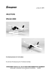
B-25 MITCHELL
Für Elektroantrieb mit 3 LiPo-Zellen
Es wird eine Fernsteuerung mit 4 Funktionen benötigt
GRAUPNER GmbH & Co. KG D-73230 KIRCHHEIM/TECK GERMANY
Änderungen vorbehalten! Keine Haftung für Druckfehler
1
01/2008
Technische Daten
Spannweite ca.
1590 mm
Länge ü.a. ca.
1200 mm
Flächeninhalt ca.
44,5 dm²
Leergewicht ca.
1700 g
Fluggewicht je nach
Ausrüstung
2600 g
EWD
ca. 0,5°
Schwerpunktbereich gemessen
80-85 ca. mm
Vorderkante Nasenleiste
Vorwort
Es wurde besonders Wert auf ein geringes Abfluggewicht gelegt, was sich in den
Flugleistungen und Flugeigenschaften wiederspiegelt. Die Flugeigenschaften der
B-25 MITCHELL sind sehr ausgewogen. Einfacher Kunstflug ist möglich. Der Aufbau
des Modells ist überwiegend aus Balsaholz gefertigt. An besonders beanspruchten
Stellen sind Verstärkungen aus Sperrholz eingeleimt.
Rumpf, Tragflügel, Seiten- und Höhenleitwerk sind zweifarbig mit Bügelfolie
bespannt. Für die Fertigstellung sind nur wenige Arbeitsgänge notwendig, wie z.B.
das Ankleben der Seitenleitwerke, der Einbau von Motorträgern mit Motoren, des
Fahrwerks sowie die Fernlenkanlage mit ihren Anlenkungen.
Zum Fliegen des Modells reicht eine RC-Anlage mit 4 Funktionen.
Achtung: Dieses Modell ist kein Spielzeug!
Sollten Sie mit solch motorisiertem Modell keine Erfahrung haben, wenden Sie sich
bitte an erfahrene Modellflieger, die Sie unterstützen können. Es könnte zu
Verletzungen kommen, wenn das Modell ohne Vorkenntnisse in Betrieb genommen
wird. Denken Sie an die Sicherheit und Ihre Gesundheit.
Wichtige Sicherheitshinweise
Sie haben einen Bausatz erworben, aus dem – zusammen mit entsprechendem
geeignetem Zubehör – ein funktionsfähiges RC-Modell fertiggestellt werden kann.
Die Einhaltung der Montage- und Betriebsanleitung im Zusammenhang mit dem
Modell sowie die Installation, der Betrieb, die Verwendung und Wartung der mit dem
Modell zusammenhängenden Komponenten können von GRAUPNER nicht
überwacht werden. Daher übernimmt GRAUPNER keinerlei Haftung für Verluste,
Schäden oder Kosten, die sich aus dem fehlerhaften Betrieb, aus fehlerhaftem
Verhalten bzw. in irgendeiner Weise mit dem vorgenannten zusammenhängend
ergeben. Soweit vom Gesetzgeber nicht zwingend vorgeschrieben, ist die
Verpflichtung der Firma GRAUPNER zur Leistung von Schadensersatz, aus welchem
Grund auch immer ausgeschlossen (inkl. Personenschäden, Tod, Beschädigung von
Gebäuden sowie auch Schäden durch Umsatz- oder Geschäftsverlust, durch
Geschäftsunterbrechung oder andere indirekte oder direkte Folgeschäden), die von
dem Einsatz des Modells herrühren.
Die Gesamthaftung ist unter allen Umständen und in jedem Fall beschränkt auf den
Betrag, den Sie tatsächlich für dieses Modell gezahlt haben.
GRAUPNER GmbH & Co. KG D-73230 KIRCHHEIM/TECK GERMANY
Änderungen vorbehalten! Keine Haftung für Druckfehler
2
01/2008
Die Inbetriebnahme und der Betrieb des Modells erfolgt einzig und allein auf
Gefahr des Betreibers. Nur ein vorsichtiger und überlegter Umgang beim
Betrieb schützt vor Personen- und Sachschäden.
Nach der neuen Regelung des §103 Abs. 3 LuftVZO müssen alle Flugmodelle, egal
ob Slowflyer, Parkflyer, Segelflugzeuge, Flugmodelle mit Antrieben jeglicher Art vor
Aufnahme des Flugbetriebs versichert sein. Schließen Sie daher eine spezielle RCModell-Haftplichtversicherung ab. Fragen hierzu, werden Ihnen vom Fachhandel
gerne beantwortet.
Diese Sicherheitshinweise müssen unbedingt aufbewahrt werden und müssen bei
einem Weiterverkauf des Modells an den Käufer weitergegeben werden.
Garantiebedingungen
Die Garantie besteht aus der kostenlosen Reparatur bzw. dem Umtausch von
solchen Teilen, die während der Garantiezeit von 24 Monaten, ab dem Datum des
Kaufes nachgewiesene Fabrikations- oder Materialfehler aufweisen. Weitergehende
Ansprüche sind ausgeschlossen. Transport-, Verpackungs- und Fahrtkosten gehen
zu Lasten des Käufers. Für Transportschäden wird keine Haftung übernommen. Bei
der Einsendung an GRAUPNER bzw. an die für das jeweilige Land zuständige
Servicestelle sind eine sachdienliche Fehlerbeschreibung und die Rechnung mit dem
Kaufdatum beizufügen. Die Garantie ist hinfällig, wenn der Ausfall des Teils oder des
Modells von einem Unfall, unsachgemäßer Behandlung oder falscher Verwendung
herrührt.
Wichtig! Bevor Sie mit dem Bau beginnen!
Auch wenn Sie schon viele RC-Modelle gebaut haben, lesen Sie diese Anleitung
genauestens durch und kontrollieren Sie die Teile dieses Bausatzes auf
Vollständigkeit. Es wurde viel Mühe darauf verwandt, den Aufwand möglichst
einfach zu halten, ohne die Sicherheit zu beeinträchtigen.
Das weitgehend vorgefertigte Modell benötigt nur noch wenig Bauzeit. Aber die
verbleibenden Arbeiten sind wichtig und müssen sorgfältig ausgeführt werden. Von
deren einwandfreier Ausführung hängt es ab, ob das Modell letztlich die
vorgesehene Festigkeit und Flugeigenschaften haben wird; deshalb langsam und
präzise arbeiten!
Hinweise zur Folienbespannung
Auf Grund von starken Wetterveränderungen (Temperatur, Feuchtigkeit etc.) können
in der Bespannfolie kleine Falten auftreten. In seltenen Fällen auch ein Verzug der
Bauteile. Dies liegt in der Natur der Holzbauweise mit Folienbespannung. Es kann,
wie folgt, mit einem Heißluftgebläse (Fön) oder Folienbügeleisen, wie sie für den
Modellbauer angeboten werden, wieder korrigiert werden.
Falten:
Glattbügeln oder mit Warmluft anblasen und mit weichem Tuch
anreiben.
Verzogener Flügel: Flügel dem Verzug entgegen leicht verdreht aufspannen und mit
Bügeleisen oder Warmluft die Bespannung wieder glätten.
Vorsicht! Nicht mehr Wärme zuführen, als unbedingt notwendig. Bei zu heißem
Bügeleisen schmilzt die Folie und es entstehen Löcher.
GRAUPNER GmbH & Co. KG D-73230 KIRCHHEIM/TECK GERMANY
Änderungen vorbehalten! Keine Haftung für Druckfehler
3
01/2008
Wenn Blechschrauben in Holz eingeschraubt werden, diese durch Weißleim
gegen Lösen sichern: Weißleim in Bohrung einspritzen und Schraube
eindrehen.
Hinweis zur Benutzung von der B-25 Mitchell
Vor dem Versuch der ersten Inbetriebnahme muss die gesamte Betriebs- und
Montageanleitung sorgfältig gelesen werden. Sie alleine sind verantwortlich
für den sicheren Betrieb Ihres RC-Flugmodells. Bei Jugendlichen unter 14
Jahren muss der Bau und Betrieb von einem Erwachsenen, der mit den
Gegebenheiten und möglichen Gefahren eines RC-Flugmodells vertraut ist,
verantwortlich überwacht werden.
Diese Bedienungsanleitung muss sorgfältig aufbewahrt und im Falle einer
Weitergabe dem nachfolgenden Benutzer unbedingt mit ausgehändigt werden.
Fragen, die die Sicherheit beim Betrieb des RC-Flugmodells betreffen, werden
Ihnen vom Fachhandel gerne beantwortet.
Fernsteuer-Flugmodelle sind sehr anspruchsvolle und gefährliche
Gegenstände und erfordern vom Betreiber einen hohen Sachverstand, Können
und Verantwortungsbewusstsein.
Rechtlich gesehen, ist ein Flugmodell ein Luftfahrzeug und unterliegt
entsprechenden Gesetzen, die unbedingt eingehalten werden müssen. Die
Broschüre »Modellflugrecht, Paragrafen und mehr«, Best.-Nr. 8034.02, stellt
eine Zusammenfassung dieser Gesetze dar; sie kann auch beim Fachhandel
eingesehen werden. Ferner müssen postalische Auflagen, die die
Fernlenkanlage betreffen, beachtet werden. Entsprechende Hinweise finden
Sie in der Bedienungsanleitung Ihrer Fernsteueranlage.
Es dürfen nur die im Bausatz enthaltenen Teile, sowie die ausdrücklich von
uns empfohlenen Original-Graupner-Zubehör- und Ersatzteile verwendet
werden. Wird auch nur eine Komponente der Antriebseinheit geändert, ist ein
sicherer Betrieb nicht mehr gewährleistet und es erlischt jeglicher etwaiger
Garantieanspruch.
Verwenden Sie immer nur passende, verpolungssichere Steckverbindungen.
Alle
stromführenden
Leitungen,
Steckverbindungen,
sowie
die
Antriebsbatterie, bei Selbstkonfektionierung, kurzschlusssicher isolieren.
Kombinieren Sie niemals unterschiedliche, z. B. Blech- und Goldkontakte, da
hier keine sichere Funktion gewährleistet ist.
Bei Verwendung von Schaltern bzw. Reglern mit Empfängerstromversorgung
nur Steckverbindungen mit Graupner-Gold-Kontakten verwenden.
Kurzschlüsse und Falschpolungen vermeiden.
Durch die hohe Energie der LiPo-Batterien besteht Explosions- und
Brandgefahr.
Ein RC- Flugmodell kann nur funktionsfähig sein und den Erwartungen
entsprechen, wenn es im Sinne der Bauanleitung sorgfältigst gebaut wurde.
Nur ein vorsichtiger und überlegter Umgang beim Betrieb schützt vor
Personen- und Sachschäden. Niemand würde sich in ein Flugzeug setzen und
GRAUPNER GmbH & Co. KG D-73230 KIRCHHEIM/TECK GERMANY
Änderungen vorbehalten! Keine Haftung für Druckfehler
4
01/2008
ohne vorausgegangene Schulung - versuchen, damit zu fliegen. Auch
Modellfliegen will gelernt sein.
Der Hersteller hat jedoch keine Möglichkeit, den Bau und den Betrieb eines
RC- Flugmodells zu beeinflussen. Deshalb wird hiermit auf die Gefahren
nachdrücklich hingewiesen und jede Haftung dafür abgelehnt.
Bitte wenden Sie sich dazu an erfahrene Modellflieger, an Vereine oder
Modellflugschulen. Ferner sei auf den Fachhandel und die einschlägige
Fachpresse verwiesen. Am besten als Club-Mitglied auf zugelassenem
Modellflugplatz fliegen.
Sie alleine sind verantwortlich für den sicheren Betrieb Ihres RC- Flugmodells.
Fragen, die die Sicherheit beim Betrieb des RC- Flugmodells betreffen, werden
Ihnen vom Fachhandel gerne beantwortet.
Klebstoffe und Lacke enthalten Lösungsmittel, die unter Umständen
gesundheitsschädlich sein können. Beachten Sie daher unbedingt auch die
entsprechenden Hinweise und Warnungen der Hersteller.
Der Betreiber muss im Besitz seiner vollen körperlichen und geistigen
Fähigkeiten sein. Wie beim Autofahren, ist der Betrieb des Flugmodells unter
Alkohol oder Drogeneinwirkung nicht erlaubt.
Informieren Sie alle Passanten und Zuschauer vor der Inbetriebnahme über alle
möglichen Gefahren, die von Ihrem Modell ausgehen und ermahnen diese, sich
in ausreichendem Schutzabstand, wenigstens 5 m hinter der
Luftschraubenebene, aufzuhalten.
Stets mit dem notwendigen Sicherheitsabstand zu Personen oder
Gegenständen fliegen; nie Personen in niedriger Höhe überfliegen oder auf sie
zufliegen!
Modellflug darf nur bei Außentemperaturen von - 5º C bis + 35º C betrieben
werden. Extremere Temperaturen können zu Veränderungen von z. B.
Akkukapazität, Werkstoffeigenschaften und mangelhafte Klebeverbindungen
führen.
Jeder Modellflieger hat sich so zu verhalten, dass die öffentliche Sicherheit
und Ordnung, insbesondere andere Personen und Sachen, sowie die Ordnung
des Modellflugbetriebs nicht gefährdet oder gestört wird.
Das Flugmodell niemals in der Nähe von Hochspannungsleitungen,
Industriegelände, in Wohngebieten, öffentlichen Straßen, Plätzen, Schulhöfen,
Parks und Spielplätzen usw. fliegen lassen.
Warnungen müssen unbedingt beachtet werden. Sie beziehen sich auf Dinge
und Vorgänge, die bei einer Nichtbeachtung zu schweren - in Extremfällen
tödlichen Verletzungen oder bleibenden Schäden führen können.
Luftschrauben und generell alle sich drehenden Teile, die durch einen Motor
GRAUPNER GmbH & Co. KG D-73230 KIRCHHEIM/TECK GERMANY
Änderungen vorbehalten! Keine Haftung für Druckfehler
5
01/2008
angetrieben werden, stellen eine ständige Verletzungsgefahr dar. Sie dürfen
mit keinem Körperteil berührt werden! Eine schnell drehende Luftschraube
kann z. B. einen Finger abschlagen!
Sich niemals in oder vor der Drehebene von Luftschrauben aufhalten! Es
könnte sich doch einmal ein Teil davon lösen und mit hoher Geschwindigkeit
und viel Energie wegfliegen und Sie oder Dritte treffen. Darauf achten, dass
kein sonstiger Gegenstand mit einer laufenden Luftschraube in Berührung
kommt!
Die Blockierung der Luftschraube, durch irgendwelche Teile, muss
ausgeschlossen sein.
Vorsicht bei losen Kleidungsstücken wie Schals, weiten Hemden usw.: sie
werden vom Propellerstrahl angesaugt und können in den Luftschraubenkreis
gelangen.
Überprüfen Sie vor jeder Inbetriebnahme das Modell und alle an ihm
gekoppelten Teile (z. B. Luftschrauben, Getriebe, RC- Teile usw.) auf festen Sitz
und mögliche Beschädigungen. Das Modell darf erst nach Beseitigung aller
Mängel in Betrieb genommen werden.
Auf gute Standfestigkeit achten, wenn Sie das Modell in der Hand halten.
Passendes Schuhwerk, z. B. Sportschuhe tragen.
Vergewissern Sie sich, dass die verwendete Frequenz frei ist. Erst dann
einschalten! Funkstörungen, verursacht durch Unbekannte, können stets ohne
Vorwarnung auftreten! Das Modell ist dann steuerlos und unberechenbar!
Fernlenkanlage nicht unbeaufsichtigt lassen, um ein Betätigen durch Dritte zu
verhindern.
Elektromotor nur einschalten, wenn nichts im Drehbereich der Luftschraube
ist. Nicht versuchen, die laufende Luftschraube anzuhalten. Elektromotor mit
Luftschraube nur im fest eingebauten Zustand laufen lassen.
Die Fluglage des Modells muss während des gesamten Fluges immer eindeutig
erkennbar sein, um immer ein sicheres Steuern und Ausweichen zu
gewährleisten. Machen sich während des Fluges
Funktionsbeeinträchtigungen/Störungen bemerkbar, muss aus
Sicherheitsgründen sofort die Landung eingeleitet werden. Sie haben anderen
Luftfahrzeugen stets auszuweichen. Start- und Landeflächen müssen frei von
Personen und sonstigen Hindernissen sein.
Immer auf vollgeladene Akkus achten, da sonst keine einwandfreie Funktion
der RC-Anlage gewährleistet ist.
Niemals heiß gewordene, defekte oder beschädigte Batterien verwenden. Es
sind stets die Gebrauchsvorschriften des Batterieherstellers zu beachten.
Vor jedem Flug eine Überprüfung der kompletten RC-Anlage, sowie des
GRAUPNER GmbH & Co. KG D-73230 KIRCHHEIM/TECK GERMANY
Änderungen vorbehalten! Keine Haftung für Druckfehler
6
01/2008
Flugmodells auf volle Funktionstüchtigkeit und Reichweite durchführen.
Dabei ist zu beachten, dass bei der Inbetriebnahme die Motorsteuerfunktion am
Sender immer zuerst in AUS-Stellung gebracht wird. Danach Sender und dann
erst Empfangsanlage einschalten, um ein unkontrolliertes Anlaufen des
Elektromotors zu vermeiden. Gleichfalls gilt immer zuerst Empfangsanlage
ausschalten, danach erst den Sender.
Überprüfen Sie, dass die Ruder sich entsprechend der Steuerknüppelbetätigung bewegen.
Beim Bewegen des Querruder-Steuerknüppels nach rechts, muss das rechte
Querruder nach Oben und das linke Querruder nach unten ausschlagen.
Beim Bewegen des Höhen-/Tiefenruder-Knüppels nach hinten, zum Bauch,
muß das Ruder nach oben ausschlagen.
Beim Fliegen keine abrupten Steuerknüppelbewegungen durchführen.
Mit diesen Hinweisen soll auf die vielfältigen Gefahren hingewiesen werden,
die durch unsachgemäße und verantwortungslose Handhabung entstehen
können. Richtig und gewissenhaft betrieben ist Modellflug eine kreative,
lehrreiche und erholsame Freizeitgestaltung.
Hinweise zum Bau und Flugbetrieb von B-25 MITCHELL
Bevor mit dem Bau begonnen wird:
Achten Sie beim Kauf einer Funkfernsteuerung darauf, dass die Sende- und
Empfangsgeräte auch für Flugmodelle geeignet und bei der Deutschen
Bundespost-Telekom zugelassen sind, sowie eine FTZ-Serienprüfnummer besitzen.
In den Frequenzbereichen für Funkfernsteuerung werden auch andere Funkanlagen
und Hochfrequenzgeräte betrieben. Deshalb kann kein Schutz vor Störungen durch
solche Geräte gewährt werden.
Der Betrieb einer Funkfernsteuerung für Flugmodelle auf den freigegebenen
Kanälen im 35 MHz-Band sind gebührenfrei
Weitere Informationen zu diesem Thema bekommen Sie bei Ihrer örtlichen TelekomNiederlassung oder bei Ihrem Modellbau-Fachhändler.
Anleitung und Warnhinweise zur Benutzung von LiPo – Akkus
Den allgemeinen Hinweis für die Benutzung von LiPo- Akkus entnehmen
Sie bitte die dem Akkupack beiliegenden Beipackzettel.
Allgemeine Warnhinweise
Die Akkus dürfen nicht in Feuer gelangen oder eingeäschert werden.
GRAUPNER GmbH & Co. KG D-73230 KIRCHHEIM/TECK GERMANY
Änderungen vorbehalten! Keine Haftung für Druckfehler
7
01/2008
Ebenso dürfen die Zellen nicht in Flüssigkeiten wie Wasser, Meerwasser oder
Getränke eingetaucht werden. Jeder Kontakt mit Flüssigkeit gleich welcher Art ist zu
vermeiden.
Einzelne Zellen und Akkus sind kein Spielzeug und dürfen deshalb nicht in die
Hände von Kindern gelangen. Akkus/Zellen außerhalb der Reichweite von Kindern
aufbewahren.
Akkus dürfen nicht in die Nähe von Babys oder Kleinkinder gelangen. Sollten Akkus
verschluckt worden sein, so ist sofort ein Arzt oder Notarzt aufzusuchen.
Akkus dürfen nicht in eine Mikrowelle oder unter Druck geraten. Rauch und Feuer
und noch mehr können die Folgen sein.
Zerlegen Sie niemals einen LiPo-Akku. Das Zerlegen eines Akkus kann interne
Kurzschlüsse verursachen. Gasentwicklung, Feuer und Explosionen oder andere
Probleme können die Folge sein.
Die in den LiPo-Akkus enthaltenen Elektrolyte und Elektrolytdämpfe sind
gesundheitsschädlich. Vermeiden Sie in jedem Fall direkten Kontakt mit Elektrolyte.
Bei Kontakt von Elektrolyte mit Haut, Augen oder anderen Körperteilen muss ein
sofortiges Aus- oder Abspülen mit ausreichend frischem Wasser vorgenommen
werden, anschließend muss ein Arzt konsultiert werden.
Im Gerät eingebaute Akkus immer aus den Geräten entnehmen, wenn das Gerät
gerade nicht verwendet wird. Geräte nach dem Gebrauch immer ausschalten um
Tiefentladungen zu vermeiden. Akkus immer rechtzeitig aufladen. Akkus auf einer
nicht brennbaren, hitzebeständigen und nicht leitenden Unterlage lagern!
Tiefentladene Li-Po Akkus sind defekt und dürfen nicht mehr verwendet werden!
• WICHTIG: Der im Modell eingebaute Akku darf nicht im Hausmüll entsorgt
werden. Der Akku muss in Altbatterierücknahmebehältern entsorgt werden.
• WICHTIG: Das Modell und der Sender dürfen nicht im Hausmüll entsorgt werden
und müssen auf einem Wertstoffhof als Elektroschrott abgegeben werden.
Erkundigen Sie sich hierzu bei Ihrer Gemeinde.
Während der Bauphase
RC-Teile, sowie Rudergestänge werden während des Zusammenbaus nach den
entsprechenden Baustufen eingebaut. Ein späterer Einbau ist gar nicht oder nur
sehr schwierig möglich.
Die Bauanleitung
ist größtenteils in Reihenfolge gehalten. Die nachfolgenden Hinweise sollen noch
zusätzlich einige Erläuterungen geben.
Abweichungen von der aufgeführten Reihenfolge beim Bau des Modells sind nach
eigenem Ermessen vorzunehmen.
Achten Sie darauf, dass Balsamesser, Stecknadeln, dünne Drahtenden usw. spitz
bzw. scharf sind und somit leicht zu Verletzungen führen können.
Achten Sie darauf, dass Kinder keinen Zugang zu Werkzeugen, Klebstoffen oder
Lacken haben.
Sorgen Sie bei Klebstoffen mit Lösungsmitteln für einen gut belüfteten Raum.
Geben Sie Klebstoff- und Farbreste bei Sondermüllsammelstellen ab.
GRAUPNER GmbH & Co. KG D-73230 KIRCHHEIM/TECK GERMANY
Änderungen vorbehalten! Keine Haftung für Druckfehler
8
01/2008
Eine großzügig bemessene freie Arbeitsfläche ist bei allen Bastelarbeiten von
besonderem Vorteil.
Lassen Sie sich schwierige Arbeitsgänge von erfahrenen Modellbauern zeigen,
wenn Sie noch wenig Erfahrung im Modellbau haben.
Verhaltensregeln
Betreiben Sie Ihr Modell niemals auf öffentlichen Straßen, Wegen und Plätzen,
Gebäuden oder in der Nähe von Hochspannungsleitungen.
Lassen Sie die B 25 MITCHELL niemals in Naturschutz- oder
Landschaftsschutzgebieten fliegen. Nehmen Sie Rücksicht auf die dort lebenden
Tiere und Pflanzen.
Bäume und Sträucher dienen als Kinderstube, Nist- und Lebensraum von Vögeln.
Gefährden Sie niemals Tiere, Zuschauer oder andere Piloten.
Funkfernsteuerung für B 25 MITCHELL
Als Funkfernsteuerung schlagen wir folgende minimale Ausrüstung vor:
1 Computer System mx 12 im 35 MHz-Band, z. B. Best.-Nr. 4722
4 Servo C 271
Best.-Nr. 5107
1 Micro-Empfänger R 700
Best.-Nr. 3551
2 Verlängerungskabel
Best.-Nr. 3935.11
2 Verlängerungskabel
Best.-Nr. 3935.18
2 Verlängerungskabel
Best.-Nr. 3935.32
3 Verlängerungskabel
Best.-Nr. 3935.50
1 V-Kabel
Best.-Nr. 3936.11
1 Hochflexible Kupferlitze
Best.-Nr. 3389
2 Gold-Buchsen G3,5
Best.-Nr. 2969
2 Gold-Stecker G3,5
Best.-Nr. 2970
1 G3,5 verpolungssicheres Kunststoffteil
Best.-Nr. 2969.K
entsprechenden Ladegeräte dazu siehe GRAUPNER Hauptkatalog FS.
Elektroantrieb und Zubehör
2 COMPACT 350 8,4V
2 Drehzahlregler GENIUS 40
1.LiPo-Akku-Pack
2 GRAUPNER SLOWFLY PROP
2 Luftschraubenaufnahme
2 Motorträger
2 Spinner
1 Klett-Kabelbinder
Best.-Nr. 7713
Best.-Nr. 2896.G35
Best.-Nr. 7662.3
Best.-Nr. 2945.25.15
Best.-Nr. 6053.40
Best.-Nr. 7690.9
Best.-Nr. 253
Best.-Nr. 1587
Das Modell ist sehr weit und hervorragend vorgefertigt, Motorhaube und
Motorgondeln in GFK liegen dem Bausatz bei. Falls erforderlich, bügeln Sie zuerst
sämtliche bespannten Holzteile nach, insbesondere an Kanten und im Bereich von
Scharnieren bzw. Folienstößen. Es ist empfehlenswert, Anschlagseiten, an denen die
Ruderscharniere eingeklebt werden, komplett mit Tesafilm kristallklar zu überkleben,
weil unter Umständen Feuchtigkeit die Folie an solchen Stellen abheben bzw.
anlösen können.
GRAUPNER GmbH & Co. KG D-73230 KIRCHHEIM/TECK GERMANY
Änderungen vorbehalten! Keine Haftung für Druckfehler
9
01/2008
Erforderliches Material und Werkzeug
Spiralbohrer Ø 1,5 mm
Spiralbohrer Ø 2,0 mm
Schraubendreher Kreuzschlitz und Langschlitz
Sechskant- Schraubendreher
Flachzange
z.B. Best.-Nr. 574.1,5
z.B. Best.-Nr.574.2
z.B. Best.-Nr. 810
z.B. Best.– Nr.5735.1,5
Klebstoffe
Holzleim, z. B. UHU coll, Best.-Nr. 958.60
UHU hart, z. B. Best.-Nr. 534
Sekundenkleber dünnflüssig, z. B. Best.-Nr. 5822
Der Zusammenbau der B- 15 MITCHELL
Beginnen Sie erst mit dem Zusammenbau, wenn Sie sich mit den Bauteilen und
einzelnen Baustadien vertraut gemacht haben. Sollte ein Bauteil Grund zur
Beanstandung geben, so ist die vor Baubeginn Ihrem Fachhändler mitzuteilen.
Der Tragflügel
Mit einem heißen Lötkolben die Aussparungen für die Servos und
Fahrwerksaufnahmen freischmelzen.
Wie auf dem Foto zu sehen, die Gummitüllen und Hohlnieten in die Servoflansche
einsetzen.
GRAUPNER GmbH & Co. KG D-73230 KIRCHHEIM/TECK GERMANY
Änderungen vorbehalten! Keine Haftung für Druckfehler
10
01/2008
Die Servoanschlusskabel mit den entsprechenden Verlängerungskabel verlängern
und mit einem Tropfen Sekundenkleber oder Schrumpfschlauch gegen Lösen
sichern.
Servoanschlusskabel in die Tragflächenhälften einziehen, so dass die sie aus der
entsprechenden Öffnung in der Wurzelrippe herauskommt.
Wie auf dem nachfolgenden Foto zu sehen die Querruderservos in die
Tragflügelhälften einsetzen, Ø 1,5 mm bohren und anschrauben.
In die Bohrung des Servohebels wie auf dem Foto zu sehen den Gestängeanschluss
montieren.
GRAUPNER GmbH & Co. KG D-73230 KIRCHHEIM/TECK GERMANY
Änderungen vorbehalten! Keine Haftung für Druckfehler
11
01/2008
Dabei ist unbedingt darauf zu achten, dass sich dieser ohne merkliches Spiel noch
bewegen lässt.
Zum Befestigen der Querruder und Landeklappen an den Tragflügelhälften, werden
in dies die Scharniere bis zur Hälfte eingeklebt. Am besten zeichnet man die Mitte
der Scharniere mit einem Bleistift, auf den Scharnieren an. Jetzt auf Ober- und
Unterseite jedes Scharniers ein paar Tropfen dünnflüssigen Sekundenkleber geben
und Scharniere bis zur angezeichneten Mitte in die Aufnahmeschlitze schieben.
Beim Einkleben der Scharniere in die Landeklappen wird gleichzeitig der
Stahlverbinder in die Aufnahmebohrungen in den Landeklappen geklebt. Als
Klebstoff wird hierfür EPOXYD-HARZ verwendet. Zuerst in die Aufnahmebohrungen
Harz streichen, dann auf die Scharniere Sekundenkleber geben und die Ruder bis
auf einen Spalt von ca. 0,5 mm an die Endkante schieben. Bis zum Aushärten des
Klebstoffes die Ruder mittels zweier Wäscheklammern in Neutrallage fixieren.
GRAUPNER GmbH & Co. KG D-73230 KIRCHHEIM/TECK GERMANY
Änderungen vorbehalten! Keine Haftung für Druckfehler
12
01/2008
Nach dem Aushärten des Klebstoffes werden die Querruder an die Tragflächen
geklebt. Scharniere ca. 2 mm in die Aufnahmeschlitze stecken. Jetzt auf jedes
Scharnier oben und unten ein paar Tropfen dünnflüssigen Sekundenkleber geben
und Ruder an die Endkante der Tragfläche schieben, so dass noch ein Spalt von ca.
0,5 mm bleibt .
Bis zum Aushärten des Klebstoffes die beiden Elektromotoren zum Einbau
vorbereiten.
Mittels Schrauben und Einschlagmuttern die beiden Elektromotoren an die
Kopfspanten der Motorgondeln schrauben. Schrauben mit UHU schraubensicher
gegen Lösen sichern.
Bevor die Motorgondelverkleidungen angeschraubt werden, müssen die
Drehzahlregler angesteckt sein. Durch kurze Inbetriebnahme der Motoren die
Drehrichtung kontrollieren.
GRAUPNER GmbH & Co. KG D-73230 KIRCHHEIM/TECK GERMANY
Änderungen vorbehalten! Keine Haftung für Druckfehler
13
01/2008
Die Regler können mit Doppelklebeband an die Seitenwand der Träger geklebt
werden.
Die Anschlusskabel vom Regler zum Akku müssen um ca. 250 mm verlängert
werden.
Bevor die Motorgondelverkleidungen angeschraubt werden kann, müssen die
Hauptfahrwerksbeine, wie auf dem Foto zu sehen, montiert werden.
Von der zweiteiligen Motorgondelverkleidungen wird zuerst die obere und dann die
untere an den Tragflügel geschraubt.
Die obere Abdeckung von vorne auf den Tragflügel schieben, so dass die Motorwelle
mittig in die Öffnung kommt und die Abdeckung hinten mittels einer
Zylinderblechschraube befestigt werden kann.
Die untere Abdeckung so aufschieben, dass zum Einen die seitlichen
Kunststoffnasen in die Schlitze in der Tragflächenunterseite tauchen, zum Anderen
GRAUPNER GmbH & Co. KG D-73230 KIRCHHEIM/TECK GERMANY
Änderungen vorbehalten! Keine Haftung für Druckfehler
14
01/2008
die Bohrung deckungsgleich mit der Befestigungsmutter kommt. In dieser Position
die Abdeckung mittels der M4 Kunststoffschraube befestigen. Jetzt können die
beiden Luftschrauben mittels dem Aluminiumspinner befestigt werden.
Jetzt die Ruderhörner für die Querruder und Landeklappen einkleben, Gestänge
einhängen und mittels Gestängeanschluss an den Servohebeln befestigen.
Dabei unbedingt darauf achten, dass sich der Gestängeanschluss noch ohne
merkliches Spiel drehen lässt. Die Sechskantmutter gegen Lösen sichern (UHU
schraubensicher)
Zum Einstellen der Ruder in Neutralstellung muss die RC-Anlage kurz in
Betriebgenommen werden. Die Landeklappen können mittels einem Schieber oder
Mehrstufenschalter betätigt werden. Bei Position Landeklappen eingefahren befindet
sich das Servo, wie auch auf dem Foto zu sehen, nicht in Mittelstellung.
Das Höhenleitwerk mit den Seitenleitwerken
Wie schon bei den Querrudern beschrieben die Höhenruder an die Höhenflosse
kleben
GRAUPNER GmbH & Co. KG D-73230 KIRCHHEIM/TECK GERMANY
Änderungen vorbehalten! Keine Haftung für Druckfehler
15
01/2008
Unter Zugabe von Klebstoff die Ruderhörner in die beiden Höhen- und Seitenruder
kleben. Dabei darauf achten, dass der Einhängepunkt der Gestänge und der
Drehpunkt der Ruder übereinstimmt.
Wie auf dem Foto zu sehen an der Höhenflosse und den Seitenleitwerken die
Bespannfolie ablösen.
Unter Zugabe von Klebstoff (UHU hart oder UHU holzleim) die beiden
Seitenleitwerke an die Höhenflosse kleben. Dabei darauf achten, dass die
Seitenleitwerke senkrecht zu der Höhenflosse und parallel zueinander stehen
GRAUPNER GmbH & Co. KG D-73230 KIRCHHEIM/TECK GERMANY
Änderungen vorbehalten! Keine Haftung für Druckfehler
16
01/2008
Die vormontierten Umlenkhebel für die beiden Seitenruder durch Herausdrehen der
Befestigungsschraube abnehmen. Die Einhängebohrungen der Gestänge und des
Gestängeanschlusses mit entsprechendem Bohrer aufbohren. Gestängeanschluss
montieren, so dass er sich noch ohne merkliches Spiel drehen lässt. Das Gestänge
vom Betätigungsservo aus in den Umlenkhebel einhängen. Das Gestänge vom
Ruderhorn zum Umlenkhebel in Ruderhorn einhängen. Den Umlenkhebel wieder
befestigen. Durch Einspritzen von einem Tropfen Klebstoff die Befestigungsschraube
gegen Lösen sichern. Dabei darauf achten, dass das Gestänge vom Ruderhorn
durch die Querbohrung des Gestängeanschlusses geht.
Das überstehende Gestänge mit einem Seitenschneider kürzen.
Die beiden Gestänge der Seitenruder werden in der Mitte mittels einem
Gestängeanschluss ( mit Ø 2mm Querbohrung) zusammengefasst.
Klemmschraube mit UHU schraubensicher gegen Lösen sichern.
GRAUPNER GmbH & Co. KG D-73230 KIRCHHEIM/TECK GERMANY
Änderungen vorbehalten! Keine Haftung für Druckfehler
17
01/2008
Das Höhenleitwerk wird durch die Zunge vorne und hinten durch eine M4
Kunststoffschraube auf dem Rumpf befestigt
Das Fahrwerk
Zur Montage des Bugfahrwerks muss die vordere Cockpitverglasung abgenommen
werden. Den Bugfahrwerksdraht von unten zusammen mit dem Anlenkhebel in die
Aufnahmebohrungen des Lagerbocks schieben.
Hierbei muss das Anlenkgestänge bereits in der äußeren Bohrung des Anlenkhebels
eingehängt sein. Die Befestigungsschraube mit UHU schraubensicher gegen Lösen
sichern. Jetzt kann die Cockpitverglasung wieder (mit transparentem Klebfilm)
aufgeklebt werden.
Die Räder vom Bug.,- und Hauptfahrwerk jeweils mittels zwei Stellringen auf den
Achsen befestigen. Schrauben mit UHU schraubensicher gegen Lösen sichern.
Die Räder sollten sich ohne merkliches Spiel drehen lassen.
GRAUPNER GmbH & Co. KG D-73230 KIRCHHEIM/TECK GERMANY
Änderungen vorbehalten! Keine Haftung für Druckfehler
18
01/2008
Höhen- und Bugfahrwerkservo
Wie schon bei dem Servoeinbau in den Tragflächen beschrieben die beiden Servos
mit Gummitüllen und Hohlnieten versehen, in das Servobrettchen im Rumpf
einsetzen, für die Befestigungsschrauben mit Ø 1,5 mm bohren und die Servos
befestigen.
Zum Befestigen der Gestänge an den Servohebeln werden auch hier
Gestängeanschlüsse in den Servohebeln montiert. Darauf achten, dass sich die
Gestängeanschlüsse noch ohne merkliches Spiel drehen lassen. Dies ist ganz
wichtig bei dem Höhenruderservo. Die überstehenden Gestänge mit einem
Seitenschneider abschneiden.
Der Antriebsakku wird wie auf dem Foto zu sehen von der Servoseite aus in den
Akkuschacht eingeschoben bis er vorne ansteht. Mit einem Stück Schaumstoff
einklemmen und mittels eines Gummirings sichern.
Zusammenbau des Modells
Seitenruderservo am Verlängerungskabel anschließen. Steckverbindung gegen
Lösen, mit einem Klebeband oder Sicherungsclip Best.-Nr. 3503 sichern. Höhenruder
mit der Holzzunge in den Schlitz des Spantes stecken und hinten mit der M4
Kunststoffschraube befestigen.
Die beiden Tragflächenhälften mittels dem Aluminiumrohr an den Rumpf stecken und
mit jeweils zwei M4 Kunststoffschrauben befestigen . Die Kunststoffschrauben nur so
fest anziehen bis die Tragflügel unverrückbar am Rumpf anliegen.
Antriebsakku wie beschrieben in den Akkuschacht einschieben und sichern.
Rumpfabdeckung so in die Aussparung legen, dass sie vorne mit den beiden
Holzzungen in den Aussparungen des Spantes steckt und hinten mittels zweier M4
Kunststoffschrauben befestigt werden kann. Schrauben nur so fest anziehen bis die
Abdeckung unverrückbar auf dem Rumpf aufliegt.
GRAUPNER GmbH & Co. KG D-73230 KIRCHHEIM/TECK GERMANY
Änderungen vorbehalten! Keine Haftung für Druckfehler
19
01/2008
Die Abschlussarbeiten am Modell sind das Aufkleben des Dekors. Die einzelnen
Aufkleber aus dem Dekorbogen, mit leichtem transparentem Überstand,
ausschneiden und nach den Abbildungen auf dem Verpackungskarton und Titelbild
der Anleitung aufkleben.
Auswiegen der B 25 MITCHELL
Das flugfertig ausgerüstete und zusammengebaute Modell rechts und links neben
dem Rumpf, ca. 80-85 mm hinter der Tragflächennasenleiste unterstützen. Bei
korrekter Schwerpunktlage sollte das Modell sich waagerecht auspendeln, bzw. die
Rumpfnase leicht nach unten zeigen. Falls erforderlich, muss der Schwerpunkt durch
Verschieben des Antriebsakkus oder Ankleben von Blei erreicht werden. Vor dem
Erstflug müssen sämtliche Ruder, bei Sendertrimmung in Mitte, genau auf
Mittelstellung (Nullstellung) gebracht werden.
Ruderausschläge für Normalflug
Querruder
nach oben und unten 12 mm
Höhenruder
nach oben und unten 18 mm
Seitenruder
nach rechts und links 20 mm
Klappen
Start nach unten 7 mm
Klappen
Landung nach unten 23 mm
Die angegebenen Ruderausschläge werden immer an der größten Tiefe der Ruder
gemessen.
Es empfiehlt sich, senderseitig Exponentialwerte von 20 % einzustellen.
Wichtig:
Bei der Montage der Gestänge grundsätzlich sorgfältig darauf achten, dass diese
leicht laufen, ihren vollen steuerbaren Weg - einschließlich Trimmung - ausführen
können und keinesfalls mechanisch begrenzt werden.
Beim Bewegen des Steuerknüppels nach rechts, muss das Seitenruder nach rechts
ausschlagen (links/links). Beim Bewegen des Höhen-/Tiefenruder-Knüppels nach
hinten, sprich zum Bauch, müssen die Ruder nach oben ausschlagen (vorne = nach
unten). Beim Bewegen des Querruder-Steuerknüppels nach rechts, muss das rechte
Querruder nach oben, das linke nach unten ausschlagen. Beim Bewegen des
Gasknüppels nach vorne, müssen die Motoren in Vollgasstellung laufen. Bei
Gasknüppel ganz hinten müssen die Motoren stehen bleiben.
Nun bleibt nur noch viel Spaß und Freude beim Fliegen mit Ihrer B 25 MITCHELL zu
wünschen.
Ihr
Team !
GRAUPNER GmbH & Co. KG D-73230 KIRCHHEIM/TECK GERMANY
Änderungen vorbehalten! Keine Haftung für Druckfehler
20
01/2008
Réf. N° 9373
B-25 MITCHELL
Instructions de montage
Pour propulsions électriques alimentées par 3 éléments LiPo
Un ensemble R/C à 4 voies est nécessaire
Caractéristiques techniques
Envergure, env.
Longueur hors tout, env.
Surface alaire, env.
Poids à vide, env.
Poids en ordre de vol,
selon équipement
Différence de calage d’incidence
Plage de centrage mesurée derrière
le bord d’attaque de l’aile
1590mm
1200mm
44,5 dm²
1700 g.
2600 g.
env. 0,5°
env. 80-85mm
Avant-propos
Une attention particulière a été apportée pour l’obtention d’un faible poids au
décollage, lequel se reflète dans les caractéristiques et les performances de vol. Les
caractéristiques de vol du B-25 MITCHELL sont remarquables. La voltige simple est
possible. La structure du modèle est fabriquée principalement en balsa avec des
renforts en contre plaqué collés aux emplacements nécessaires.
Le fuselage, l’aile, le stabilisateur et les dérives sont recouverts en film plastique de
deux couleurs. Quelques travaux sont seulement nécessaires pour la finition du
modèle, comme par ex. le collage de l’empennage, le montage des supports avec les
moteurs, du train d’atterrissage ainsi que des éléments R/C avec leurs connexions.
Un ensemble R/C à 4 voies suffit pour le pilotage du modèle.
Attention: Ce modèle n'est pas un jouet!
Si vous n'avez encore aucune expérience avec ce genre de modèle motorisé, faitesvous assister par un modéliste expérimenté. Ce modèle peut provoquer des
blessures s'il est utilisé sans connaissances préalables. Pensez à la sécurité et à
votre santé!
Conseils de sécurité importants
Vous avez fait l'acquisition d'une boite de construction avec les accessoires
correspondants qui vont vous permettre la réalisation d'un modèle radiocommandé.
Le respect des instructions de montage et d'utilisation relatives au modèle ainsi que
GRAUPNER GmbH & Co. KG D-73230 KIRCHHEIM/TECK GERMANY
Änderungen vorbehalten! Keine Haftung für Druckfehler
21
01/2008
l'installation, l'utilisation et l'entretien des éléments de son équipement ne peuvent
pas être surveillés par la Firme GRAUPNER. C'est pourquoi nous déclinons toute
responsabilité concernent les pertes, les dommages ou les coûts résultants d'une
mauvaise utilisation ou d'un fonctionnement défectueux. Tant qu'elle n'y a pas été
contrainte par le législateur, la responsabilité de la Firme GRAUPNER n'est
aucunement engagée pour les dédommagements (incluant les dégâts personnels,
les cas de décès, la détérioration de bâtiments ainsi que le remboursement des
pertes commerciales dues à une interruption d'activité ou à la suite d'autres
conséquences directes ou indirectes) provenant de l'utilisation du modèle.
L'ensemble de sa responsabilité est en toutes circonstances et dans chaque cas
strictement limitée au montant que vous avez réellement payé pour ce modèle.
L'utilisation du modèle se fait uniquement aux risques et périls de son
utilisateur. Seule une utilisation prudente et responsable évitera de causer des
dégâts personnels et matériels.
Les modèles motorisés de tous genres doivent être assurés avant leur utilisation.
Contractez pour cela une assurance spéciale pour les modèles radiocommandés.
Demandez à votre revendeur qui vous renseignera volontiers.
Ces conseils de sécurité devront être soigneusement conservés et remis à l’acheteur
en cas de revente du modèle.
Conditions de garantie:
La garantie comprend la réparation gratuite ou l'échange des pièces présentant un
défaut de fabrication ou de matière pendant une durée de 24 mois, à compter de la
date de l'achat. Toutes autres réclamations sont exclues. Les frais de transport et
d'emballage sont à la charge de l'acheteur. Nous déclinons toute responsabilité pour
les détériorations survenues au cours du transport. Le retour au Service après Vente
GRAUPNER, ou du Pays concerné doit être accompagné d'une description du
défaut constaté et de la facture correspondante avec la date de l'achat. Le bénéfice
de la garantie sera perdu lorsque le défaut de la pièce ou du modèle sera dû à un
accident, à une manipulation incorrecte ou à une mauvaise utilisation
Important! A lire avant de commencer la construction!
Même si vous avez déjà construit de nombreux modèles R/C, veuillez lire
attentivement ces instructions et vérifier si les pièces contenues dans cette boite de
construction sont complètes. Beaucoup d'efforts ont été faits pour rendre la
construction la plus simple possible, sans pour autant nuire à la sécurité
Ce modèle largement préfabriqué ne nécessite encore que peu de temps pour sa
finition. Mais les travaux restants sont importants et devront être effectués avec soin.
De leur parfaite exécution dépendront la solidité finale prévue pour le modèle et ses
performances de vol; c'est pourquoi il conviendra de travailler avec patience et
précision!
Conseils pour le film de recouvrement:
En raison des fortes variations climatiques (Température, humidité, etc…) le
recouvrement en film plastique peut présenter des petits plis. Ceci est du à la nature
de la construction en bois avec ce genre de recouvrement. Il pourra être retendu à
GRAUPNER GmbH & Co. KG D-73230 KIRCHHEIM/TECK GERMANY
Änderungen vorbehalten! Keine Haftung für Druckfehler
22
01/2008
l'aide d'un séchoir électrique comme ceux utilisés en modélisme, en procédant
comme suit:
Plis :
Chauffer le film et le frotter avec un chiffon doux.
Aile déformée: Tordre légèrement l'aile dans le sens contraire à la déformation pour
détendre le recouvrement et le retendre en appliquant l'air chaud.
Précaution! Ne pas appliquer plus de chaleur que nécessaire. Un fer à repasser
trop chaud fera fondre le film et il en résultera un trou!
Lorsque des vis parker devront être filetées dans du bois, elles seront
bloquées contre tout risque de desserrage avec de la colle blanche: injecter la
colle dans le perçage et fileter la vis.
Conseils pour l’utilisation du B-25 Mitchell
Avant de tenter la première mise en service, les instructions de montage et
d’utilisation devront être attentivement lus. Vous être seul responsable de la
sécurité d’utilisation de votre modèle R/C. Les jeunes gens en dessous de 14
ans devront effectuer les assemblages et utiliser le modèle sous la surveillance
d’un adulte familiarisé avec les particularités et les dangers possibles que peut
présenter un modèle R/C.
Ces instructions d’utilisation devront être conservées avec soin afin de
pouvoir les remettre à l’utilisateur suivant en cas de vente du modèle.
Demandez à votre revendeur les mesures de sécurité à prendre avec
l’utilisation d’un modèle R/C, il vous renseignera volontiers.
Les modèles d'avions R/C sont des appareils pouvant être dangereux et qui
exigent de leur utilisateur une grande compétence et la conscience de sa
responsabilité.
Un modèle réduit volant est comparable à un véritable aéronef pour lequel
toutes les dispositions légales doivent être prises; la possession d'une
assurance est obligatoire.
Il conviendra d'utiliser exclusivement les éléments fournis dans la boite de
construction ainsi que les accessoires d'origine Graupner et les pièces
détachées conseillées. Si un seul composant de la propulsion est remplacé,
une parfaite sécurité de fonctionnement de peut plus être assurée et peut
entraîner la perte du bénéfice de la garantie.
Utilisez toujours des connecteurs adaptés entre eux avec sécurité contre les
inversions de polarité. Tous les conducteurs de courant, les connexions ainsi
que les batteries de confection personnelle devront être isolés contre les
courts circuits.
Ne combinez jamais des connecteurs différents, par ex. des contacts en tôle
avec des contacts dorés, car ici aucune sécurité de fonction ne pourra être
garantie.
Avec l’utilisation des commutateurs et des régulateurs assurant l’alimentation
de la réception, utilisez uniquement des connecteurs Graupner à contacts
dorés.
GRAUPNER GmbH & Co. KG D-73230 KIRCHHEIM/TECK GERMANY
Änderungen vorbehalten! Keine Haftung für Druckfehler
23
01/2008
Evitez les courts circuits et les inversions de polarité.
Par la forte énergie emmagasinée par les batteries LiPo, il existe un danger
d’explosion et d’incendie.
Un modèle volant R/C ne peut évoluer correctement que s'il a été construit et
réglé conformément aux instructions de montage et seule une utilisation
prudente et responsable évitera de provoquer des dommages matériels ou
corporels. Le pilotage sûr d’un modèle réduit n’est possible qu’après un
entraînement ou un écolage appropriés.
Le fabricant n'a cependant aucune possibilité d'influencer la construction et
l'utilisation d'un modèle de sa production. C'est pourquoi nous attirons ici
l'attention sur les dangers représentés en dégageant toute responsabilité.
Faites-vous assister par un modéliste expérimenté, ou inscrivez-vous dans une
association ou dans une école de pilotage. Consultez en outre votre revendeur
et la Presse spécialisée. Le mieux est de faire partie d'un club d'aéromodélisme
pour pouvoir voler sur un terrain autorisé.
Les colles et les peintures contiennent des solvants qui dans certaines
conditions peuvent être nocifs pour la santé. Pour cette raison, observez
impérativement le mode d'emploi et les avertissements indiqués par le
fabricant correspondant.
L'utilisateur doit être en pleine possession de ses facultés physiques et
mentales. Comme pour la conduite des automobiles, le pilotage des modèles
volants sous l'effet de l'alcool ou de la drogue n'est pas autorisé.
Avant de faire voler votre modèle, informez tous les passants et les
spectateurs sur les dangers qu'il peut présenter et demandez-leur de se tenir à
une distance de sécurité d’au moins 5 m derrière le champ de rotation de
l’hélice.
Tenez-vous à une distance de sécurité suffisante de personnes ou d'objets; ne
survolez jamais de personnes à basse altitude et ne volez jamais dans leur
direction.
Un modèle volant R/C ne doit voler que par des températures extérieures
comprises entre – 5° à + 35°C. Des températures extrêmes peuvent conduire
par ex. à une modification de la capacité des accus, des propriétés des
matériaux et de la résistance des collages.
Chaque modéliste doit se comporter de façon à ce que l'ordre et la sécurité
publique, vis-à-vis des autres personnes et des biens, ainsi que l'activité des
autres modélistes ne soient pas mis en danger, ni perturbés.
Ne faites jamais voler votre modèle à proximité des lignes à haute tension,
dans les zones industrielles, les agglomérations, sur les voies publiques, les
places, dans les cours d'école, les parcs et les aires de jeux, etc…
GRAUPNER GmbH & Co. KG D-73230 KIRCHHEIM/TECK GERMANY
Änderungen vorbehalten! Keine Haftung für Druckfehler
24
01/2008
Les avertissements donnés devront être impérativement respectés. Leur non
observation peut conduire à de sérieux dommages et dans les cas extrêmes à
des blessures graves.
Les hélices et en général toutes les pièces mécaniques entraînées par un
moteur présentent un danger de blessures permanent et ne doivent être
touchées par aucune partie du corps! Une hélice tournant à haut régime peut
par ex. couper un doigt!
Ne vous tenez jamais dans le champ de rotation d'une hélice! Une pièce peut
se détacher et être éjectée à haute vitesse avec une forte inertie et vous
toucher, ou une tierce personne. Veillez également à ce qu'aucun objet
quelconque vienne en contact avec l'hélice en rotation.
Le blocage d’une l’hélice par un objet quelconque doit absolument être exclu.
Veillez également aux vêtements flottants tels qu'écharpe ou cravate, etc…qui
peuvent être aspirés et s'enrouler sur l'hélice.
Avant chaque utilisation, vérifiez le modèle et toutes les pièces qui y sont
rattachées (par ex. hélice, réducteur, éléments R/C, etc…) pour détecter une
possible détérioration. Ce n'est qu'après avoir remédié à tous les défauts
éventuels que le modèle pourra être mis en vol.
Assurez-vous que la fréquence que vous utilisez est libre avant de mettre
votre émetteur en contact! Une perturbation peut toujours se produire pour
une cause inconnue, sans prévenir! Le modèle devient alors incontrôlable et
livré à lui-même! Ne laissez pas votre émetteur sans surveillance pour éviter
une manipulation par un tiers.
Ne mettez les moteurs électriques en contact que lorsque rien ne se trouve
dans le champ de rotation des hélices. Faites tourner les moteurs électriques
avec l’hélice montée uniquement lorsqu’ils sont solidement fixés dans le
modèle.
La position du modèle doit être nettement identifiable durant tout le vol pour
garantir un pilotage sûr. Si vous remarquez l'influence d'une perturbation
durant le vol, préparez-vous immédiatement à atterrir pour des raisons de
sécurité. Durant le départ et le processus d'atterrissage, le terrain doit être
libre de toute personne et d'obstacle.
Veillez toujours au bon état de charge des accus, car autrement le parfait
fonctionnement de l'ensemble R/C ne peut être garanti.
N’utilisez jamais de batteries échauffées, défectueuses ou détériorées.
Observez les prescriptions d’utilisation indiquées par le fabricant des
batteries
Avant chaque vol, effectuez une vérification complète du bon fonctionnement
de l’installation R/C ainsi que du modèle et faites un essai de portée.
GRAUPNER GmbH & Co. KG D-73230 KIRCHHEIM/TECK GERMANY
Änderungen vorbehalten! Keine Haftung für Druckfehler
25
01/2008
Pour faire un essai de fonctionnement des moteurs, assurez-vous d’abord que
l’organe de commande soit sur la position COUPE sur l’émetteur. Mettez
ensuite d’abord l’émetteur en contact, ensuite la réception pour éviter un
démarrage involontaire des moteurs. Procédez inversement pour couper le
contact ; d’abord celui de la réception, ensuite celui de l’émetteur.
Vérifiez si les gouvernes se déplacent dans le sens correspondant des
manches de commande.
Ne donnez aucun ordre de commande brutal en vol.
Ces conseils mettent en évidence la diversité des dangers pouvant résulter
d'une manipulation incorrecte et irresponsable. Leur observation permettra de
pratiquer en toute sécurité ce loisir créatif et éducatif que représente
l'aéromodélisme.
Instructions et avertissements pour l’utilisation des accus LiPo
Pour l’utilisation des accus LiPo, relevez les conseils généraux donnés sur
l’étiquette jointe aux packs d’accus.
Avertissements généraux
Les accus ne devront pas être jetés au feu ni être incinérés. Les éléments ne
devront pas non plus être trempés dans des liquides, comme l’eau, l’eau de mer,
etc... Tout contact avec des liquides du même genre doit être évité.
Les éléments seuls et les packs d’accus ne sont pas des jouets et pour cette raison,
ils devront être conservés hors de la portée des enfants.
Ne jamais démonter un accu LiPo sous peine de provoquer un court-circuit interne.
Un dégagement de gaz, une mise à feu, une explosion ou un autre problème
peuvent s’ensuivre.
L’électrolyse et ses vapeurs contenues dans les accus LiPo sont nocives pour la
santé. Eviter tout contact direct avec l’électrolyse. En cas de contact avec la peau,
les yeux ou toute autre partie du corps, se rincer abondamment à l’eau fraîche et
consulter ensuite un médecin.
Les accus incorporés dans un appareil devront être retirés de celui-ci lorsqu’il n’est
pas utilisé. Couper toujours l’appareil après son utilisation pour éviter une décharge
profonde. Charger toujours régulièrement les accus. Charger les accus sur une base
non inflammable, résistante à la chaleur et non conductrice !
Les accus LiPo profondément déchargés sont défectueux et ne devront plus être
utilisés !
Important : Les accus et les appareils électroniques usagés ne devront pas être
jetés dans une poubelle domestique, mais dans un container spécialement réservé
à leur récupération pour le recyclage. Renseignez-vous auprès de l’administration
de votre commune.
Durant les assemblages
Les éléments R/C ainsi que les transmissions de gouverne devront être installés au
cours des stades de montage correspondants. Un montage ultérieur ne serait que
très difficile, voire impossible !
GRAUPNER GmbH & Co. KG D-73230 KIRCHHEIM/TECK GERMANY
Änderungen vorbehalten! Keine Haftung für Druckfehler
26
01/2008
Les instructions de montage
Elle sont- rédigées en grande partie dans l’ordre des assemblages à effectuer. Les
conseils qui vont suivre donnent encore quelques explications supplémentaires.
Quelques déviations dans l’ordre indiqué pour les assemblages pourront être
décidées sur initiative personnelle.
Notez qu’un couteau à balsa, les épingles, les fils métalliques fins, etc… sont
coupants et pointus et peuvent facilement provoquer des blessures.
Veillez à ce que les jeunes enfants n’aient pas accès aux outils, aux colles ou aux
peintures.
Utilisez les colles contenant un solvant dans un local bien aéré.
Jetez les restes de colle et de peinture dans un container spécial réservé à cet
usage.
Une surface de travail largement dimensionnée est toujours avantageuse pour tous
les travaux de bricolage.
Si vous n’avez encore que peu d’expérience en modélisme, faites-vous montrer les
travaux difficiles à exécuter par un modéliste expérimenté.
Règles du comportement
Ne faites jamais voler votre modèle sur les voies publiques, les routes et les places,
ou à proximité des habitations et des lignes à haute tension.
Ne faites pas voler le B-25 Mitchell dans une nature protégée. Prenez en
considération les lieux où vivent les animaux et les plantes.
Les arbres et les buissons servent de nids et d’habitats aux oiseaux.
Ne mettez jamais en danger les animaux, les spectateurs ou les autres pilotes.
Equipement R/C pour le B-25 Mitchell
L’équipement minimum suivant est conseillé :
1 Ensemble R/C à micro-ordinateur mx-12, 41 MHz, par ex. Réf. N°4723.41
4 Servos C 271
Réf. N°5107
1 Micro récepteur R 700
Réf. N°7051.41
2 Cordons de rallonge
Réf. N°3935.11
2 Cordons de rallonge
Réf. N°3935.18
2 Cordons de rallonge
Réf. N°3935.32
2 Cordons de rallonge
Réf. N°3935.50
1 Cordon en V
Réf. N°3936.11
1 Fil de cuivre ultra souple
Réf. N°3389
GRAUPNER GmbH & Co. KG D-73230 KIRCHHEIM/TECK GERMANY
Änderungen vorbehalten! Keine Haftung für Druckfehler
27
01/2008
2 Fiches mâles G3,5
Réf. N°2969
2 Fiches femelles G3,5
Réf. N°2970
1 Sécurité contre les inversions de polarités
Réf. N°2969.K
Pour le chargeur correspondant, voir dans le catalogue général FS.
Propulsions électriques et accessoires
2 COMPACT 350 8,4V
2 Régulateurs de vitesse GENIUS 40
1 Pack d’accus LiPo
2 Hélices GRAUPNER SLOWFLY PROP
2 Accouplements d’hélice
2 Supports moteur
2 Cônes d’hélice
1 Collier d’attache à crampons
Réf. N°7713
Réf. N°2896.G3,5
Réf. N°7662.3
Réf. N°2945.25.15
Réf. N°6053.40
Réf. N°7690.9
Réf. N°253
Réf. N°1587
Ce modèle est très largement et remarquablement préfabriqué. Les capots et les
nacelles moteur en fibre de verre sont livrés dans le kit de montage. Si nécessaire,
repassez d’abord au fer les raccordements du film de recouvrement sur l’ensemble
des pièces en bois, particulièrement sur les bords et au niveau des charnières. Il est
conseillé de recoller complètement toutes les faces sur lesquelles seront collées les
charnières des gouvernes avec du ruban Tesafilm cristal, parce que dans certaines
conditions d’humidité, le film de recouvrement peut se soulever et se décoller sur de
tels endroits
Matériel et outils nécessaires
Foret de Ø 1,5 mm
Foret de Ø 2,0 mm
Tournevis cruciforme et à lame
Tournevis six pans
Pinces plates
Par ex. Réf. N°574.1,5
Par ex. Réf. N°574.2
Par ex. Réf. N°810
Par ex. Réf. N°5735.1,5
Colles
Colle blanche, par ex. UHU coll, Réf. N°958.60
UHU hart, par ex. Réf. N°534
Colle seconde fluide, par ex. Réf. N°5822
Les assemblages du B- 25 MITCHELL
Commencez les assemblages lorsque vous serez familiarisé avec les pièces et les
différents stades de montage. Si l’une des pièces fait l’objet d’une réclamation,
consultez votre revendeur également avant de commencer les assemblages.
L’aile
Dégager les ouvertures pour les servos et les supports du train d’atterrissage avec la
panne d’un fer à souder chaud.
Insérer les passe fils an caoutchouc et les oeillets dans les pattes des servos,
comme montré sur la photo.
GRAUPNER GmbH & Co. KG D-73230 KIRCHHEIM/TECK GERMANY
Änderungen vorbehalten! Keine Haftung für Druckfehler
28
01/2008
Rallonger le cordon des servos avec les cordons de rallonge correspondants et fixer
les connecteurs avec quelques gouttes de colle seconde ou un morceau de gaine
thermo rétractable.
Enfiler les cordons de servo dans les panneaux d’aile de façon à ce qu’ils sortent par
l’ouverture correspondante dans la nervure d’emplanture.
Mettre en place les servos d’aileron dans les panneaux d’aile, comme montré sur les
photos suivantes, percer les avant trous de Ø 1,5 mm et les fixer.
Monter un raccord de tringlerie sur le palonnier des servos, comme montré sur la
photo.; veiller à ce qu’ils puissent pivoter librement, sans jeu notable.
Pour monter les volets d’ailerons et d’atterrissage sur les panneaux d’aile, les
charnières seront collées jusqu’à leur moitié dans ces derniers. Le mieux sera de
tracer le milieu de chaque charnière avec un crayon, appliquer maintenant un peu de
colle seconde sur le dessus et le dessous de chacune et les insérer dans les
encastrements jusqu’au milieu tracé.
Pour le collage des charnières dans les volets d’atterrissage, la pièce de liaison en fil
d’acier sera collée en même temps dans le perçage des volets. de la RESINE
EPOXY sera utilisée ici pour les collages. Appliquer d’abord la résine dans le
perçage des volets, ensuite de la colle seconde sur les charnières et insérer celles-ci
dans les encastrements jusqu’à ce qu’il subsiste un espace d’env. 0,5mm entre le
volet et le bord de fuite de l’aile. Fixer les volets en position neutre au moyen de deux
pinces à linge jusqu’au durcissement de la colle. .
Après la prise de la colle, les volets d’aileron seront montés sur l’aile. Introduire les
charnières dans les encastrements sur env. 2mm. Appliquer maintenant un peu de
colle seconde sur le dessus et le dessous de chaque charnière et les pousser dans
les encastrements jusqu’à ce qu’il subsiste un espace d’env. 0,5mm entre le volet et
le bord de fuite de l’aile.
Durant la prise de la colle, les deus moteurs électriques seront préparés pour leur
montage.
Fixer les deux moteurs électrique sur le couple avant des nacelles avec les vis et les
écrous spéciaux ; bloquer les vis avec du freine filet UHU.
Avant de fixer les carénages des nacelles moteur, les régulateurs de vitesse devront
être connectés ; contrôler le sens de rotation de moteurs par une courte mise en
service.
Les régulateurs pourront être fixés sur le côté des supports avec de la bande
adhésive double face.
Le cordon de raccordement des régulateurs à l’accu devra être rallongé sur env.
250mm.
GRAUPNER GmbH & Co. KG D-73230 KIRCHHEIM/TECK GERMANY
Änderungen vorbehalten! Keine Haftung für Druckfehler
29
01/2008
Avant de pouvoir fixer les carénages des nacelles moteur, les jambes du train
principal devront être montées, comme montré sur la photo.
Pour le montage des carénages des nacelles en deux pièces, fixer d’abord celle
supérieure et ensuite celle inférieure sur l’aile.
Pousser le recouvrement supérieur par l’avant sur l’aile de façon à ce que l’arbre du
moteur vienne au milieu de l’ouverture et que le recouvrement puisse être fixé à
l’arrière avec une vis parker à tête cylindrique.
Pousser le recouvrement inférieur de façon à ce que l’une des pattes latérales en
plastique pénètre dans la fente à l’intrados de l’aile et que l’autre vienne en
superposition du perçage avec l’écrou de fixation. Dans cette position, fixer le
recouvrement avec la vis en plastique M4. Les deux hélices pourront maintenant être
fixées au moyen des cônes en aluminium.
Coller maintenant les guignols de gouverne sur les volets d’ailerons et d’atterrissage,
connecter les tringleries et les fixer dans le raccord de tringlerie sur le palonnier des
servos.
Veiller absolument à ce que les raccords de tringlerie puissent encore pivoter
librement sans jeu notable ; bloquer l’écrou six pan avec du freine filet UHU.
L’ensemble R/C devra être mis provisoirement en service pour le réglage de la
position neutre des gouvernes Les volets d’atterrissage pourront être commandés
par un curseur linéaire pour par un commutateur à trois positions. Dans la position
rentrée des volets d’atterrissage, le servo ne se trouve pas en position neutre,
comme montré sur la photo.
Le stabilisateur avec les dérives
Monter la gouverne de profondeur sur le plan fixe du stabilisateur avec les
charnières, comme il a déjà été décrit pour les volets d’ailerons.
Coller les guignols sur les gouvernes de profondeur et de direction. Veiller à ce que
le point de connexion de la tringlerie et le point d’articulation de la gouverne
correspondent.
Retirer le film de recouvrement sur les gouvernes de profondeur et de direction
comme montré sur la photo.
Coller les deux dérives sur le plan fixe du stabilisateur (UHU hart ou UHU coll).
Veiller à ce que les dérives soient perpendiculaires au plan fixe du stabilisateur et
parallèles entre elles.
Retirer le palonnier de renvoi prémonté pour les deux gouvernes de direction en
desserrant la vis de fixation. Repercer les trous de fixation et les raccords de
tringlerie avec un foret d’un diamètre correspondant .Monter les raccords de tringlerie
de façon à ce qu’ils puissent pivoter sans jeu notable. Connecter la tringlerie venant
du servo de direction sur le palonnier de renvoi. Connecter la tringlerie venant du
palonnier de renvoi sur les guignols de gouverne. Remonter maintenant le palonnier
de renvoi. Bloquer la vis de fixation en appliquant une goutte de colle. Veiller à ce
GRAUPNER GmbH & Co. KG D-73230 KIRCHHEIM/TECK GERMANY
Änderungen vorbehalten! Keine Haftung für Druckfehler
30
01/2008
que la tringlerie venant du guignol passe au travers du perçage du raccord de
tringlerie.
Bloquer la vis de serrage avec du freine filet UHU.
Le stabilisateur sera fixé sur le fuselage par la languette à l’avant et par une vis en
plastique M4 à l’arrière.
Le train d’atterrissage
Le vitrage du cockpit avant devra être retiré pour le montage de la jambe avant du
train d’atterrissage. Introduire la jambe en fil d’acier avec le levier de commande par
le dessous dans le palier.
Pour cela, la tringlerie de commande devra déjà être connectée sur le trou extérieur
du levier. Bloquer la vis de fixation avec du freine filet UHU. Le vitrage du cockpit
avant pourra maintenant être remis en place et collé avec du film adhésif transparent.
Les roues de la jambe avant et du train principal seront retenues sur leur axe entre
deux bagues d’arrêt. Bloquer la vis pointeau des bagues d’arrêt avec du freine filet
UHU ; les roues doivent pouvoir tourner sans jeu notable.
Servos de profondeur et de commande de la jambe avant
Munir les deux servos des passe fils en caoutchouc et des œillets comme il a déjà
été décrit, les mettre en place dans le fuselage, percer les avant trous de Ø 1,5 mm
et les fixer.
Un raccord de tringlerie sera aussi monté ici sur le palonnier des deux servos. Veiller
à nouveau à ce qu’ils puissent pivoter librement, sans jeu notable ; ceci est très
important pour le servo de profondeur. Coupez la longueur excédentaire des
tringleries avec des pinces coupantes.
L’accu de propulsion sera introduit dans le logement devant les servos et poussé
jusqu’en avant ; le bloquer avec de la mousse collée et le fixer avec une bande
élastique.
Assemblage du modèle
Relier le servo de direction au cordon de rallonge et fixer les connecteurs avec du
ruban adhésif ou un clip de sécurité, Réf. N°3503. Introduire la languette en bois du
stabilisateur dans la fente du fuselage et le fixer à l’arrière avec la vis en plastique
M4.
Monter les deux panneaux d’aile sur le fuselage au moyen du tube d’aluminium et les
fixer chacun avec deux vis en plastique M4. Serrer juste suffisamment les vis en
plastique jusqu’à ce que les panneaux soient bien immobilisés contre le fuselage.
Introduire l’accu de propulsion dans son logement et le fixer comme déjà décrit.
Placer le recouvrement du fuselage dans l’ouverture de façon à ce que les deux
languettes en bois à l’avant s’engagent des les fentes du couple et qu’il puisse être
fixé à l’arrière avec deux vis en plastique M4. Serrer juste suffisamment les vis en
plastique jusqu’à ce que le recouvrement soit bien immobilisé sur le fuselage.
GRAUPNER GmbH & Co. KG D-73230 KIRCHHEIM/TECK GERMANY
Änderungen vorbehalten! Keine Haftung für Druckfehler
31
01/2008
Le travail final sur le modèle consistera à la pose des décorations. Découper les
différents motifs sur la planche de décoration en laissant un léger bord transparent et
les coller sur le modèle conformément aux illustrations sur le carton d’emballage et
sur celle en en-tête de ces instructions.
Centrage du B 25 MITCHELL
Soutenir le modèle entièrement équipé et en ordre de vol sous l’aile, à droite et à
gauche de chaque côté du fuselage, sur un point situé à env. 80-85mm derrière le
bord d’attaque de l’aile. Avec un centrage correct, le modèle doit se tenir en équilibre
sur ce point, avec le nez du fuselage penchant légèrement vers le bas. Le centrage
correct sera obtenu, si nécessaire, par le déplacement en correspondance de l’accu
de propulsion ou par l’ajout d’un lest en plomb.
Avant le premier vol, toutes les gouvernes devront être réglées exactement en
position neutre avec les leviers de trim sur l’émetteur.
Débattements des gouvernes pour le vol normal
Ailerons
12mm vers le haut et vers le bas
Profondeur
18mm vers le haut et vers le bas
Direction
20mm vers la droite et vers la gauche
Volets d’atterrissage
Décollage, 7mm vers le bas
Atterrissage, 23mm vers le bas
Les débattements indiqués sont toujours mesurés sur la plus grande largeur des
gouvernes
Il est conseillé de régler une valeur de 20% d’exponentiel dans l’émetteur.
Important :
Lors du montage des tringleries, veillez à ce qu’elles puissent se mouvoir librement
sur toute la course du servo, incluant le trim, sans être limitées mécaniquement.
En déplaçant le manche de commande de direction vers la droite, la gouverne de
direction doit se braquer vers la droite (et vers la gauche, à gauche). En tirant le
manche de commande de profondeur vers l’arrière (à soi), la gouverne de profondeur
soit se soulever (et en la poussant vers l’avant, s’abaisser). En déplaçant le manche
de commande des ailerons vers la droite, le volet droit doit se soulever et le gauche
s’abaisser. En poussant le manche de commande des gaz en avant, les moteurs
doivent tourner à pleine puissance et être coupés en le tirant vers l’arrière.
Il nous reste à vous souhaiter beaucoup de plaisir avec les vols de votre B 25
MITCHELL !
Votre équipe Graupner !
GRAUPNER GmbH & Co. KG D-73230 KIRCHHEIM/TECK GERMANY
Änderungen vorbehalten! Keine Haftung für Druckfehler
32
01/2008
Order No. 9373
INSTRUCTIONS
B-25 MITCHELL
For electric power system and 3 LiPo cells
This model requires a four-function radio control system
Specification
Wingspan approx.
Overall length approx.
Wing area approx.
Empty weight approx.
All-up weight according to fittings
Longitudinal dihedral approx.
Centre of Gravity range, measured
from the root leading edge, approx.
1590 mm
1200 mm
44.5 dm²
1700 g
2600 g
0.5°
80 - 85 mm
Introduction
At the design stage we placed particular emphasis on low take-off weight, and this is
reflected in the model’s excellent performance and flight handling. The B-25
MITCHELL’s flying characteristics are nicely balanced, and the aeroplane is also
capable of simple aerobatic manoeuvres. The model is primarily of balsa
construction, with plywood reinforcements at highly stressed areas.
The fuselage, wing panels, fins and tailplane are supplied ready-built, and covered in
two-colour iron-on film. To complete the model the builder is required to carry out
very little work, which includes fitting the tail panels, installing the motor mounts and
motors, undercarriage, receiving system and control surface linkages.
A five-function radio control system is sufficient to fly the model.
Caution: this model is not a toy!
If you are a beginner to this type of powered model, please ask an experienced
model flyer for help and support. If you attempt to operate the model without knowing
what you are doing, you could easily injure yourself or somebody else. Please keep
your safety and well-being in mind at all times.
Important Safety Notes
You have acquired a kit which can be assembled into a fully working RC model when
fitted out with suitable accessories. However, we as manufacturers have no control
over the way you build and operate your RC model aircraft, nor how you install,
operate and maintain the associated components, and for this reason we are obliged
to deny all liability for loss, damage or costs which are incurred due to the incorrect
GRAUPNER GmbH & Co. KG D-73230 KIRCHHEIM/TECK GERMANY
Änderungen vorbehalten! Keine Haftung für Druckfehler
33
01/2008
use of our products or due to incompetent behaviour on the part of the user, or which
are connected with such operation in any way. Unless otherwise prescribed by
binding law, the obligation of the GRAUPNER company to pay compensation,
regardless of the legal argument employed, is excluded. This includes personal
injury, death, damage to buildings, damages due to loss of business or turnover,
interruption of business or other direct or indirect consequent damage whose root
cause was the operation of the model.
The total liability in all cases and under all circumstances is limited to the amount of
money which you actually paid for the model.
This model is built and flown at the sole and express responsibility of the
operator. The only way to avoid injury to persons and damage to property is to
handle and operate the model with the greatest care and consideration at all
times.
According to the new regulation of §103 Paragraph 3 of the LuftVZO (German
Aviation Approvals Office), all model aircraft - whether slow-flyer, park-flyer, glider, or
model aircraft propelled by any form of power plant - must be insured before the
model is operated. If you are not sure about this, please ask at your local model shop
where the staff will be glad to advise you.
These safety notes must be kept in a safe place. If you ever dispose of the model, be
sure to pass them on to the new owner.
Guarantee terms
The guarantee covers replacement of any parts which can be shown to exhibit
manufacturing faults or material defects within the guarantee period of 24 months
from the initial date of purchase. No other claims will be considered. Cost of
transport, packing and freight are payable by the purchaser. We accept no liability for
damage in transit. When you send the product to GRAUPNER, or to the approved
Service Centre for your country, you must include a clear and concise description of
the fault together with the invoice showing the date of purchase. The guarantee is
invalid if the component or model fails due to an accident, incompetent handling or
incorrect usage.
Important: before you start construction
Even if you have already built a large number of RC models please read right through
these instructions and check all the kit components against the parts list. We have
taken great trouble to keep construction as simple as possible, without making any
compromises in the area of safety.
This model is highly pre-fabricated and can be built in a very short time.
However, the work which you have to carry out is important and must be done
carefully. The model will only be strong and fly well if you complete your tasks
competently - so please work slowly and accurately.
Note regarding the film covering
Minor creases or bubbles may develop in the film covering due to major fluctuations
in weather conditions (temperature, humidity etc.); in rare cases you may even find a
slight warp in a component. These minor faults are in the nature of film-covered built-
GRAUPNER GmbH & Co. KG D-73230 KIRCHHEIM/TECK GERMANY
Änderungen vorbehalten! Keine Haftung für Druckfehler
34
01/2008
up wooden structures, and can easily be corrected using a heat gun, as commonly
used for modelling.
Creases:
Wing warp:
Blow warm air over the area and rub down with a soft cloth.
Hold the panel twisted gently in the opposite direction to the warp,
and apply warm air to remove the creases from the covering.
Caution! do not heat the film more than is absolutely necessary. If the air or the
iron is too hot, the film may melt and holes may be formed.
When self-tapping screws have to be screwed into wood, apply a little white
glue to prevent them shaking loose: just squirt a little glue into the hole and fit
the screw.
Operating the B-25 MITCHELL
Be sure to read right through the assembly and operating instructions before
you attempt to fly this model for the first time. You alone are responsible for
the safe operation of your radio-controlled model. Young persons under
fourteen years should only be permitted to operate this model under the
instruction and supervision of an adult who is aware of the hazards involved in
this activity.
Please keep these operating instructions in a safe place. If you ever dispose of
the model, be sure to pass them on to the new owner.
If you have any questions regarding the safe operation of your RC model
aeroplane, please turn to your local model shop in the first instance, as the
staff will be pleased to help you.
Radio-controlled model aircraft are extremely demanding and potentially
dangerous objects, and require a high level of expertise, skill and
responsibility from the operator.
In legal terms our models are classed as aircraft, and as such are subject to
legal regulations and restrictions which must be observed at all times. Our
brochure “Modellflugrecht, Paragrafen und mehr” (Model Aviation Law, Legal
Requirements and more) is available under Order No. 8034.02, and contains a
summary of all these rules. Your local model shop should have a copy which
you can read. There are also Post Office regulations concerning your radio
control system, and these must be observed. Refer to your RC system
instructions for more details.
Be sure to use only those parts included in the kit, together with other genuine
Graupner accessories and replacement parts as recommended expressly by
us. Even if you change a single component you can no longer be sure that the
system will work reliably, and such changes also invalidate your guarantee.
It is important to use matching polarised electrical connectors. All high-current
cables, connectors and the drive battery terminals must be insulated to prevent
GRAUPNER GmbH & Co. KG D-73230 KIRCHHEIM/TECK GERMANY
Änderungen vorbehalten! Keine Haftung für Druckfehler
35
01/2008
short-circuits, especially if you attach the connectors yourself. Never combine
different types of connector, e.g. tin-plated and gold-plated contacts, as they
cannot be expected to work reliably in the long-term.
If you are using a BEC speed controller or switch (integral receiver power
supply), it must be fitted with Graupner gold-contact connectors.
Avoid short-circuits and reversed polarity.
The high energy density of Li-Po batteries involves a risk of fire and even
explosion.
A radio-controlled model aircraft can only work properly and fulfil your
expectations if it is built very carefully and in accordance with the building
instructions. If you wish to avoid injuring people and damaging property it is
essential to be careful and painstaking at all stages of building and operating
your model. Successful model flying is only possible with suitable training and
plenty of practice.
As manufacturers we are not in a position to influence the way you build and
operate your RC model aircraft, and for this reason we deny all liability. All we
can do is expressly point out the hazards involved in this activity.
We suggest that you ask an experienced model flyer for help, or join a model
club or flight training school. Your local model shop and the specialist
magazines are excellent sources of information. If at all possible, it is always
best to join a club and fly at the approved model flying site.
You alone are responsible for the safe operation of your radio-controlled
model.
If you have any questions regarding the safe operation of your RC model
aeroplane, please turn to your local model shop in the first instance, as the
staff will be pleased to help you.
Adhesives and paints contain solvents which may be hazardous to health
under certain circumstances. Read and observe the notes and warnings
supplied by the manufacturer of these materials.
The operator of the model must be in full possession of his or her bodily and
mental faculties. As with car driving, operating a model aircraft under the
influence of alcohol or drugs is not permissible under any circumstances.
If there are passers-by or spectators at your flying site, make sure that they are
aware of the dangers inherent in your activity before you start the motor, and
insist that they keep a safe distance away (at least 5 m behind the rotational
plane of the propeller).
Always keep a safe distance away from people and objects when flying; never
fly low over people’s heads, and never fly directly towards them.
Radio-controlled models should only be flown in “normal” weather conditions,
i.e. a temperature range of -5° to +35° C. More extreme temperatures can lead
GRAUPNER GmbH & Co. KG D-73230 KIRCHHEIM/TECK GERMANY
Änderungen vorbehalten! Keine Haftung für Druckfehler
36
01/2008
to changes in battery capacity and material characteristics, weakened glued
joints and other unwanted effects.
All model flyers should behave in a way that minimises the danger to people
and property. Never act in any manner which will disturb other flyers and
jeopardise safe, orderly flying at the site.
Never operate your model aircraft close to high-tension overhead cables,
industrial sites, residential areas, public roads, squares, school playgrounds,
public parks or sports grounds etc.
Don’t ignore our warnings. They refer to materials and situations which, if
ignored, can result in fatal injury or permanent damage.
Propellers and other rotating parts which are powered by a motor constitute a
permanent hazard and represent a real risk of injury. Don’t touch them with any
part of your body. For example, a propeller spinning at high speed can easily
cut your finger badly.
Keep well clear of the rotational plane of the propeller. You never know when
some part may come loose and fly off at high speed, hitting you or anybody
else in the vicinity. Never touch the revolving propeller with any object.
Ensure that it is impossible for any object to stall or block the propeller.
Take care with loose clothing such as scarves, loose shirts etc. Flapping cloth
can easily be sucked into the area of the propeller and then get tangled in the
blades; this is extremely dangerous.
Every time you intend to operate your model check carefully that it and
everything attached to it (e.g. propeller, gearbox, RC components etc.) is in
good condition and undamaged. If you find a fault, do not fly the model until
you have corrected it.
Whenever you are holding the model make sure that you are standing on a
stable surface and cannot slip. Wear shoes with high-grip soles, such as
trainers.
Satisfy yourself that your frequency is vacant before you switch on. Radio
interference caused by unknown sources can occur at any time without
warning. If this should happen, your model will be uncontrollable and
completely unpredictable. Never leave your radio control system unguarded,
as another person might pick it up and try to use it.
Do not switch the electric motors on unless you are sure that there is nothing
in the rotational plane of the propeller. Never attempt to stop the spinning
propellers. Electric motors with the propeller attached should only be run when
firmly mounted.
GRAUPNER GmbH & Co. KG D-73230 KIRCHHEIM/TECK GERMANY
Änderungen vorbehalten! Keine Haftung für Druckfehler
37
01/2008
If you are to fly your model safely and avoid problems, it is essential that you
are aware of its position and attitude throughout each flight - so don’t let it fly
too far away! If you detect a control problem or interference during a flight,
immediately land the model to prevent a potential accident. Models must
always give way to full-size aircraft. Take-off and landing strips should be kept
free of people and other obstacles.
Your RC system can only work reliably if the batteries are kept fully charged.
Never use batteries which are hot, faulty or damaged. At all times heed the
instructions provided by the battery manufacturer.
Before each flight check that all functions on the model aircraft are working
correctly, and that the radio control system is in good order and operating at
full range.
Note that the motor control (throttle) function on the transmitter must always
be moved to the OFF position as the first stage in preparing for a flight. To
avoid the danger of the electric motor bursting into life unexpectedly, always
switch on the transmitter first, and only then the receiving system. The
opposite applies at the end of a flight: always switch off the receiving system
first, and finally the transmitter.
Check that the control surfaces follow the movement of the transmitter sticks:
Move the aileron stick to the right, and the right-hand aileron should deflect up,
the left-hand aileron down.
Pull the elevator stick back towards you, and both elevators must deflect up.
Move the transmitter controls smoothly at all times; don’t jerk the sticks about
abruptly when the model is in the air.
Please don’t misunderstand the purpose of these notes. We only want to make
you aware of the many dangers and hazards which can arise if you work
carelessly or irresponsibly. If you take reasonable care, model flying is a highly
creative, instructive, enjoyable and relaxing pastime.
Building and flying the B-25 MITCHELL
Before you start construction:
If you are buying a radio control system for your new model, ensure that the
transmitter and receiving system are expressly stated to be suitable for use in model
aircraft, and bear the appropriate approval stickers.
The frequency bands used for the radio control of models are also employed by other
radio transmitting and RF equipment. For this reason it is not possible to be
completely sure that no interference will occur when you are flying your model.
No licence fee is payable for using approved RC equipment to control a model
aircraft on the appropriate channels in the 35 MHz band.
GRAUPNER GmbH & Co. KG D-73230 KIRCHHEIM/TECK GERMANY
Änderungen vorbehalten! Keine Haftung für Druckfehler
38
01/2008
For more information on this subject please contact your local telecommunications
centre, or ask at your nearest model shop.
Instructions and warnings relating to the use of LiPo batteries
Please read the instruction sheet included with every battery pack for general
information about the use of LiPo batteries.
General warnings
These batteries must not come into contact with fire or ashes.
Do not let the cells contact fluids such as fresh water, salt water or drinks. Avoid
contact with liquids of all types.
Individual cells and batteries are by no means toys, and must never be allowed to get
into the hands of children. Store cells and batteries well out of the reach of children.
Batteries must not be left within reach or in the vicinity of babies or toddlers. If a child
should swallow a battery, call for a doctor or emergency medical assistance without
delay.
Batteries must not be placed in a microwave oven, nor subjected to pressure: the
results may be smoke and fire or worse.
Never attempt to dismantle Li-Po cells. Taking a battery apart can cause internal
short-circuits, which could result in gassing, fire, explosion and other problems.
The electrolyte and electrolytic fumes contained in LiPo batteries are injurious to
health. Avoid direct contact with the electrolyte at all costs. If the material gets in your
eyes, on your skin or other part of your body, it is essential to wash the affected area
immediately with copious amounts of clean water. Consult a doctor as soon as
possible thereafter.
Batteries installed in a device should always be removed from the apparatus if it is
not to be used again in the immediate future. Always switch off such devices after
use to avoid discharging the cells to a dangerous level. Recharge the batteries in
good time. Store batteries on a non-flammable, heat-resistant and non-conductive
surface. If you allow a Li-Po battery to become deep-discharged, it will inevitably be
ruined, and must not be used again.
• IMPORTANT: when the flight battery is exhausted, you must not dispose of it in
the household waste. Take the pack to your local battery reclamation centre.
• IMPORTANT: when the useful life of the model and the transmitter are over, do
not discard them in the domestic rubbish. The electric and electronic components
in particular must be taken to your nearest electrical recycling centre. Ask your
local authority if you are not sure of its location.
During construction
The receiving system components and control surface linkages should be installed at
the appropriate stage of assembly, as described in these instructions, as it may be
very difficult or even impossible to fit them later.
The building instructions
GRAUPNER GmbH & Co. KG D-73230 KIRCHHEIM/TECK GERMANY
Änderungen vorbehalten! Keine Haftung für Druckfehler
39
01/2008
In general terms the instructions reflect the sequence of assembly. The notes below
are intended to explain certain additional points of construction.
You may wish to alter the order of assembly; this should not cause problems, but
please think carefully about the consequences of any change you make.
Bear in mind that tools such as balsa knives, modelling pins, the ends of thin wire etc.
are sharp or pointed, and can cause injury if not handled with due care.
Ensure that children do not have access to tools, adhesives and paints.
When using solvent-based glue be sure to work in a well-ventilated room.
Take waste adhesives and paints to your nearest toxic waste collection point.
An unobstructed work area of generous size is very helpful for all types of modelling
activity.
If you are a beginner to modelling and are not sure about any of the more difficult
processes, ask an experienced modeller for advice and help.
Rules of behaviour
Never fly your model from a public road, path or square, or in the vicinity of buildings
or high-tension overhead cables.
Don’t fly your B-25 MITCHELL in nature reserves, protected areas or SSSIs (Sites of
Special Scientific Interest). Please have respect for the animals and plants which live
in and around your flying site.
Bear in mind that trees and bushes are the living space and nesting sites of birds,
and should not be disturbed unnecessarily.
Never endanger animals, spectators or other pilots.
Radio control system for the B-25 MITCHELL
The following items represent the minimum equipment for this model:
1
7
1
2
2
2
3
1
1
2
2
1
mx-12 computer RC system, 35 MHz band, e.g.
C 271 servo
R 700 micro-receiver
Servo extension lead
Servo extension lead
Servo extension lead
Servo extension lead
Y-lead
High-flex copper cable
G3.5 gold-contact socket
G3.5 gold-contact plug
G3.5 polarised plastic housing
Order No. 4722
Order No. 5107
Order No. 3551
Order No. 3935.11
Order No. 3935.18
Order No. 3935.32
Order No. 3935.50
Order No. 3936.11
Order No. 3389
Order No. 2969
Order No. 2970
Order No. 2969.K
Please see the main GRAUPNER FS catalogue for details of suitable battery
chargers.
Electric power system and accessories
GRAUPNER GmbH & Co. KG D-73230 KIRCHHEIM/TECK GERMANY
Änderungen vorbehalten! Keine Haftung für Druckfehler
40
01/2008
2
2
1
2
2
2
2
1
COMPACT 350 8.4 V
GENIUS 40 speed controller
LiPo flight battery
GRAUPNER SLOWFLY PROP
Propeller coupling
Motor mount
Spinner
Velcro cable tie
Order No. 7713
Order No. 2896.G35
Order No. 7662.3
Order No. 2945.25.15
Order No. 6053.40
Order No. 7690.9
Order No. 253
Order No. 1587
The model is extremely highly pre-fabricated, and is built to a superb standard of
quality. The kit includes GRP cowls and engine nacelles as standard. Please check
first that the covering film is stuck down all round, and run a film iron along the seams
if you are not sure. This applies in particular to hinge slots and film overlaps. We
recommend that you apply clear adhesive tape over the faces into which the control
surface hinges are to be fitted, because moisture tends to creep under the film at
such areas, causing it to lift.
Materials and tools required
Twist drill, 1.5 mm Ø
Twist drill, 2.0 mm Ø
Screwdriver, cross-point / slot-head
Allen-tip screwdriver
Flat-nose pliers
e.g. Order No. 574.1,5
e.g. Order No. 574.2
e.g. Order No. 810
e.g. Order No. 5735.1,5
Adhesives
White glue, e.g. UHU coll, Order No. 958.60
UHU hart, e.g. Order No. 534
Low-viscosity cyano-acrylate (“thin cyano”), e.g. Order No. 5822
Assembling the B-25 MITCHELL
Please don’t start building the model until you have examined the components and
studied the individual stages of construction, so that you have a clear understanding
how it goes together. If you are not satisfied with any component, take it back to your
supplier (model shop) before carrying out any work on it.
The wing
Use the tip of a hot soldering iron to melt away the covering film over the servo
openings and the undercarriage slots in the wing panels.
Press the rubber grommets and metal spacers into the mounting lugs of the servos,
as shown in the photo.
Connect the servo leads to the appropriate extension leads, and secure each
connection with a drop of cyano or a heat-shrink sleeve.
GRAUPNER GmbH & Co. KG D-73230 KIRCHHEIM/TECK GERMANY
Änderungen vorbehalten! Keine Haftung für Druckfehler
41
01/2008
Draw the leads through the wing panels, so that the connectors exit the holes in the
root ribs.
Place the aileron servos in the wing panels as shown in the following photo. Drill 1.5
mm Ø pilot-holes, working through the metal spacers, and fit the retaining screws to
secure the servos.
Fit the swivel pushrod connectors in the holes in the servo output arms, as shown in
the photo.
Check that the connector barrels rotate smoothly, but without noticeable slop.
The ailerons and landing flaps are attached to the wings using hinges, which should
first be glued in the control surfaces to half their depth. We recommend that you draw
a centreline on the hinges using a pencil. Apply a few drops of thin cyano to the top
and bottom of each hinge, and push them into the slots as far as the marked
centreline.
The steel rod joiners have to be glued in the holes and slots in the flaps at the same
time as you install the hinges. We recommend EPOXY GLUE for this. First apply
epoxy to the slots and holes for the flap joiners, then apply cyano to the hinges and
push the flaps fully into position, leaving a gap about 0.5 mm wide along the hinge
axis. While the epoxy is hardening, fix the flaps at the neutral position using two
clothes pegs on each side.
The ailerons can be attached permanently to the wings once the glue has set hard:
push the ailerons onto the projecting hinges to a depth of about 2 mm. Apply a few
drops of thin cyano to the top and bottom of each hinge, then push the ailerons fully
onto the hinges, leaving a gap about 0.5 mm wide along the pivot axis.
The two electric motors can be prepared for installation while the glue is hardening:
Attach the electric motors to the nose bulkheads of the engine nacelles using the
screws and captive nuts supplied. Apply a drop of UHU schraubensicher (thread-lock
fluid) to the screws to prevent them working loose.
Note that the speed controllers must be connected to the motors before the nacelle
fairings are screwed in place; run the motors briefly to ensure that they are rotating in
the correct direction.
The speed controllers can be fixed to the side of the motor mounts using doublesided foam tape.
The leads between the speed controllers and the battery need to be extended by
about 250 mm.
GRAUPNER GmbH & Co. KG D-73230 KIRCHHEIM/TECK GERMANY
Änderungen vorbehalten! Keine Haftung für Druckfehler
42
01/2008
The main undercarriage units should also be installed, as shown in the photo, before
the engine nacelle fairings are attached.
The engine nacelle fairings are two-part mouldings; the upper section is screwed to
the wing first, followed by the lower section.
Slide the upper nacelle fairing onto the wing from the front, and position it with the
motor shaft in the centre of the front opening. It should now be possible to fit a panhead self-tapping screw at the rear to hold the fairing in place.
Fit the lower nacelle fairing in such a way that the lateral plastic lugs engage in the
slots in the underside of the wing, and the hole lines up correctly with the retaining
nut. In this position fit the M4 plastic screw to secure the fairing. The propeller can
now be fitted on the motor shaft using the aluminium spinner. Repeat the procedure
with the second engine nacelle.
The next step is to glue the horns in the ailerons and landing flaps. Connect the preformed pushrods to the horns, then connect the plain ends to the swivel pushrod
connectors mounted on the servo output arms.
Ensure that the swivel pushrod connectors are free to rotate smoothly, but without
significant slop. Apply a drop of thread-lock fluid to the hexagon nuts to prevent them
working loose.
To adjust the ailerons and flaps you will need to connect the RC system and switch
the transmitter and receiver on briefly. The landing flaps can be operated either by a
slider or a multi-position switch. Note that the flap servos should be offset from centre
when the landing flaps are at the “retracted” (neutral) position, as shown in the photo.
Tailplane and fins
Attach the elevators to the tailplane using the method described for the ailerons.
Glue the horns in the pairs of elevators and rudders, taking care to line up the linkage
holes in the horns with the hinge pivot axis.
Peel off the covering film from the joint areas of the tailplane and fins, as shown in
the photo.
Apply glue (UHU hart or UHU white glue) to the tips of the tailplane, and glue the fins
in place. Ensure that both fins are at right-angles to the tailplane, and parallel to each
other.
GRAUPNER GmbH & Co. KG D-73230 KIRCHHEIM/TECK GERMANY
Änderungen vorbehalten! Keine Haftung für Druckfehler
43
01/2008
The two rudders are actuated by a factory-fitted bellcrank; remove the bellcrank by
undoing the retaining screw. Drill out the holes for the pushrods and the swivel
pushrod connector using the appropriate sizes of drill. Fit the swivel connector,
ensuring that it rotates smoothly, but without noticeable slop. Connect the pushrod
from the rudder servo to the bellcrank, then connect the pushrods from the horns to
the bellcrank before re-installing the bellcrank. A drop of glue injected into the hole
for the retaining screw will prevent it working loose. Ensure that the pushrods from
the horns run through the cross-hole in the swivel pushrod connector.
Snip off excess pushrod material using side-cutters.
The two rudder pushrods are joined in the centre using the swivel pushrod connector
(with 2 mm Ø cross-hole).
Apply UHU schraubensicher to the clamping screw to prevent it working loose.
Locate the hardwood tongue at the leading edge of the tailplane, slide it into the slot
in the fuselage, and fit the M4 plastic screw to secure it.
The undercarriage
The forward cockpit glazing must be removed before the noseleg can be installed.
Slip the noseleg through the holes in the bracket from the underside, fitting the
steering lever at the same time.
Note that the steering pushrod has to be connected to the outermost hole in the
steering lever before you install the noseleg. Apply a drop of UHU schraubensicher to
the retaining screw to prevent it working loose. The cockpit glazing can now be fixed
to the fuselage using clear adhesive tape.
The main and nose wheels can now be fitted to the wheel axles; each is retained
using a collet on each side. Apply a drop of UHU schraubensicher to the collet
screws to prevent them working loose. Check that the wheels rotate freely, but
without excessive slop.
Elevator and nosewheel servos
Press the rubber grommets and tubular metal spacers into the servo mounting lugs,
as described for the aileron servos in the wing. Place the servos in the servo plate in
the fuselage, drill 1.5 mm Ø pilot-holes for the retaining screws, and fit the screws to
secure the servos.
Swivel pushrod connectors are again fitted to the servo output arms in order to
connect the pushrods to the servos. Ensure that the swivel connectors rotate freely,
without significant slop; this is particularly important for the elevator servo. Snip off
excess pushrod material using side-cutters.
GRAUPNER GmbH & Co. KG D-73230 KIRCHHEIM/TECK GERMANY
Änderungen vorbehalten! Keine Haftung für Druckfehler
44
01/2008
The flight battery should be fitted in the battery compartment from the servo end, as
shown in the photo, and slid forward as far as it will go. Push a block of foam behind
the battery to prevent it shifting, and secure it with a rubber band.
Assembling the model
Connect the rudder servo to the extension lead, and secure the connection by
wrapping it with adhesive tape; alternatively use a retainer clip, Order No. 3503. Fit
the hardwood tongue on the tailplane into the slot in the fuselage former, and fit the
M4 plastic retaining screw at the rear.
Fit the aluminium joiner tube through the fuselage and slide both wing panels onto it;
each panel is secured using two M4 plastic screws. Don’t over-tighten the screws;
tighten them just to the point where the wings are held securely against the fuselage.
Slide the flight battery into its compartment, and secure it as described earlier.
Place the fuselage hatch in the recess, and engage the two hardwood lugs in the
slots in the former. The hatch can now be secured by fitting two M4 plastic screws at
the rear. Tighten the screws just to the point where the hatch is firmly fixed to the
fuselage.
The final task is to apply the decals to the finished model. Cut out the individual
emblems from the decal sheet, leaving a narrow excess of clear material around
each one. Apply the decals to the model in the arrangement shown in the kit box
illustration and the title picture.
Balancing the B-25 MITCHELL
Install all the airborne equipment in the model, assemble it fully, ready for flight, and
support it on both sides of the fuselage at a point about 80 - 85 mm aft of the wing
root leading edge. When the CG position is correct, the model will balance level, with
the nose inclined slightly down. If necessary you can correct the CG by adjusting the
position of the flight battery (preferable) or by adding nose or tail ballast. Before the
first flight check that all the control surfaces are exactly at centre (neutral setting) with
the transmitter trims central.
Control surface travels for normal flying
Ailerons
12 mm up, 12 mm down
Elevator
18 mm up, 18 mm down
Rudder
20 mm right, 20 mm left
Flaps
take-off: 7 mm down
Flaps
landing: 23 mm down
All stated travels are measured at the widest point of the control surfaces.
We recommend that you set 20% exponential travel (Expo) on all the flying controls
at the transmitter.
Important:
When fitting and adjusting the various linkages you should ensure that they move
freely, without binding, are able to move to their full extent - including trim travel - and
are not obstructed mechanically at any point.
GRAUPNER GmbH & Co. KG D-73230 KIRCHHEIM/TECK GERMANY
Änderungen vorbehalten! Keine Haftung für Druckfehler
45
01/2008
When you move the rudder stick to the right, the rudders should also deflect to the
right (left stick: left rudder). Pull the elevator stick back towards you, and the
elevators must deflect up (stick forward: elevator down). If you move the aileron stick
to the right, the right aileron should rise, the left aileron fall. When you move the
throttle stick forward, the motor should run to the full-throttle position, i.e. full power.
Now it only remains for us to wish you every success and many enjoyable flights with
your B-25 MITCHELL.
Yours - the Graupner team
GRAUPNER GmbH & Co. KG D-73230 KIRCHHEIM/TECK GERMANY
Änderungen vorbehalten! Keine Haftung für Druckfehler
46
01/2008