1
Français
English
Overview
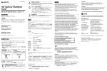
The HFBK-HD1 is an optional board designed to be
installed in the following apparatuses:
• HFU-X310 HD Camera Interface Unit
• BRC-H700 HD 3CCD Color Video Camera
• BRU-H700 HD Optical Multiplex Unit
The board supplies images from the color video camera
connected to the apparatus that accommodates the board
as HD SDI signals. It also has a 15-pin connector for
analog output (Y/Pb/Pr or RGB).
Locations and Functions of Parts
MONITOR
HD-SDI
HD-SDI
3HD-SDI connectors (BNC type)
For digital video output. The two connectors output the same
signal.
Specifications
General
Power requirements
+12 V DC, 400 mA (supplied from the
apparatus that accommodates the board)
Operating temperature
5°C to 40°C (41°F to 104°F)
Storage temperature
–20°C to +60°C (–4°F to +140°F)
Storage humidity 20% to 90% (relative, no condensation)
Dimensions
134 × 26.2 × 112.8 mm (w/h/d)
(53/8 × 11/16 × 41/2 inches)
not including projecting parts
Mass
Approx. 0.16 kg (6 oz)
Description générale
La HFBK-HD1 est une carte en option conçue pour être
installée dans les appareils suivants :
• Interface caméra HD HFU-X310
• Camera vidéo couleur HD 3CCD BRC-H700
• Module multiplex optique HD BRU-H700
La carte fournit des images provenant d’une caméra vidéo
couleur connectée à l’appareil qui contient la carte comme
signaux HD SDI. Elle comporte aussi un connecteur à 15
broches pour une sortie analogique (Y/Pb/Pr ou RVB).
Emplacement et fonction des pièces
MONITOR
HD-SDI
HD-SDI
HFBK-HD1
HFBK-HD1
3 HD-SDI connectors
Outputs
HD-SDI
2 DIP switches (behind the cover)
1 MONITOR connector
MONITOR
Output level
1MONITOR connector (D-sub 15-pin)
For analog video output. The configuration of the output
signal can be specified by setting the DIP switches.
Pin assignment
2DIP switches
To configure the type of output from the MONITOR
connector.
Note
Turn the apparatus that accommodates the board off
before changing the DIP switch settings.
Switch 1 (VD/Sync)
Selects the signal to be supplied from pin 14 of the
MONITOR connector:
Upper (Sync): To output composite sync (3-level sync)
(factory setting)
Lower (VD): To output vertical sync
Switch 2 (Sync)
Specifies whether to add a sync signal to each of the R, G,
and B signals when the RGB output is selected:
Upper (Add Sync): To output each of the R, G, and B
signals with a sync signal (factory setting)
Lower (No Sync): Not to add any sync
Switch 3 (RGB/YPbPr)
Selects the type of component output from the
MONITOR connector:
Upper (YPbPr): To output component signals (factory
setting)
Lower (RGB): To output RGB signals
BNC type (2)
Conforms to SMPTE292M, 75 Ω
D-sub 15-pin (1)
Component:
Y: 1.0 Vp-p
Pb, Pr: 0.7 Vp-p, 75 Ω
R/G/B: 1.0 Vp-p, 75 Ω
HD/VD: TTL level
Sync: 0.6 Vp-p, 75 Ω (3-level sync)
5
6
15
2 Commutateurs DIP (derrière le cache)
1 Connecteur MONITOR
1Connecteur MONITOR (D-sub 15 broches)
Pour une sortie vidéo analogique. La configuration du signal
de sortie peut être spécifiée en réglant les commutateurs DIP.
2Commutateurs DIP
Pour configurer le type de sortie du connecteur MONITOR.
1
10
3 Connecteurs HD-SDI
11
Remarque
Pin
Signal
Pin
Signal
Pin
Signal
1
R/Pr (X)
6
R/Pr (G)
11
NC
2
G/Y (X)
7
G/Y (G)
12
NC
3
B/Pb (X)
8
B/Pb (G)
13
HD
4
NC
9
NC
14
VD/SYNC
5
GND
10
GND
15
NC
Supplied accessory
Operation Manual (1)
Design and specifications are subject to change without
notice.
Mettez l’appareil contenant la carte hors tension avant de
changer les réglages des commutateurs DIP.
Commutateur 1 (VD/Synchro)
Permet de sélectionner le signal fourni par la broche 14 du
connecteur MONITOR.
Position supérieure (Synchro) : Sortie d’un signal de
synchro composite (synchro 3 niveaux) (réglage d’usine)
Position inférieure (VD) : Sortie d’un signal de synchro
verticale
Commutateur 2 (Synchro)
Permet de spécifier si un signal de synchro sera ajouté à
chacun des signaux R, V et B lorsque la sortie RVB est
sélectionnée.
Position supérieure (Ajout de synchro) : Sortie de chacun
des signaux R, V et B avec un signal de synchro (réglage
d’usine)
Position inférieure (Pas de synchro) : Pas d’ajout de signal
de synchro
Commutateur 3 (RVB/YPbPr)
Permet de sélectionner le type de signaux composantes sortis
par le connecteur MONITOR.
Position supérieure (YPbPr) : Sortie de signaux
composantes (réglage d’usine)
Position inférieure (RVB) : Sortie de signaux RVB
3Connecteurs HD-SDI (type BNC)
Pour une sortie vidéo numérique. Les deux connecteurs
sortent le même signal.
Spécifications
Généralités
Alimentation
+12 V CC, 400 mA (fourni par
l’appareil contenant la carte)
Température de fonctionnement
5 °C à 40 °C (41 °F à 104 °F)
Température de rangement
–20 °C à +60 °C (–4 °F à +140 °F)
Humidité de rangement
20 % à 90 % (relatif, sans
condensation)
Dimensions
134 × 26,2 × 112,8 mm (l/h/p)
(53/8 × 11/16 × 41/2 pouces)
pièces saillantes non comprises
Poids
Environ 0,16 kg (6 oz)
Sorties
HD-SDI
Type BNC (2)
Conforme à SMPTE292M, 75 Ω
MONITOR
D-sub 15 broches (1)
Niveau de sortie
Composantes :
Y : 1,0 Vc-c
Pb, Pr : 0,7 Vc-c, 75 Ω
R/V/B : 1,0 Vc-c, 75 Ω
HD/VD : Niveau TTL
Synchro : 0,6 Vc-c, 75 Ω (synchro 3
niveaux)
Affectation des broches
5
1
15
11
6
10
Broche Signal
Broche Signal
Broche Signal
1
R/Pr (X)
6
R/Pr (G)
11
NC
2
V/Y (X)
7
V/Y (G)
12
NC
3
B/Pb (X)
8
B/Pb (G)
13
HD
4
NC
9
NC
14
VD/SYNC
5
GND
10
GND
15
NC
Accessoires fournis
Mode d’emploi (1)
La conception et les spécifications sont susceptibles d’être
modifiées sans préavis.