1
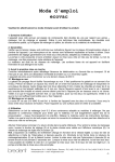
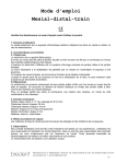
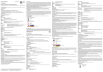
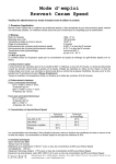
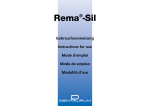
Gebrauchsanweisung
Muffel-System thermopress 400
D
Bitte diese Gebrauchsanweisung vor dem Produkteinsatz ausführlich lesen!
Für Schäden, die durch Nichtbeachtung dieser Gebrauchsanweisung entstehen, lehnt der Hersteller jede Haftung
ab.
1. Produktbeschreibung
Das thermopress 400 Muffel-System (REF 110 0040 4) ist eine Übertragungshilfe aus rostfreiem Stahl, welche aus insgesamt
5 Bestandteilen besteht, um Einbettmassenmuffeln in thermopress 400 Spritzgussgeräten einsetzen und verarbeiten zu
können. Dadurch kann der Anwender Wachsmodellationen nach zahntechnisch bekannten Verfahren modellieren, anstiften
und einbetten. In dem Lieferumfang ist zusätzlich noch ein Umbausatz (Druckplatte mit Gewindestange) beigelegt. Dadurch
ist dem Anwender möglich, auch bei älteren thermopress 400 Geräten das Muffelsystem verarbeiten zu können.
Im Lieferumfang sind folgende Systemkomponenten enthalten:
- thermopress 400 Metallrahmen
(REF 360 0128 7)
- thermopress 400 Bodenplatte
(REF 360 0128 6)
- thermopress 400 Sockelformer
(REF 360 0128 5)
- thermopress 400 Silikonmanschette mit O-Ring (REF 360 0128 0)
- thermopress 400 Umbausatz für ältere Geräte (REF 360 0128 8)
2. Indikationen/Einsatzbereich
Das thermopress 400 Muffel-System dient der Verarbeitung der thermoplastischen Werkstoffe Bio XS und bre.dentan HP.
Durch die individuelle Expansionssteuerung der zu verwendeten Einbettmasse (Brevest Rapid 1) ist es möglich, mit den
biokompatiblen Kunststoffen (Bio XS und bre.dentan HP) des thermopress-Systems, festsitzenden Zahnersatz (Kronen und
Brücken) schnell und einfach herzustellen.
3. Kontraindikationen
Das thermopress 400 Muffel-System ist nicht für die Verarbeitung anderer thermoplastischer Werkstoffe, wie z.B. bre.
crystal HP, Bio Dentaplast, bre.flex, bre.flex 2nd edition geeignet. Auch für die Verarbeitung von thermoplastischen Mitbewerberwerkstoffen kann die Fa. bredent keine Verarbeitungsangaben geben. Die Verwendung des Muffel-Systems in
anderen Kunststoffspritzgussgeräten beruht auf eigene Gefahr.
4. Gefahren- und Sicherheitshinweise
Achtung:
Vor dem Spritzvorgang muss die Muffel auf 150° C für 45 Minuten lang vorgewärmt werden. Dadurch besteht Verbrennungsgefahr beim Übersetzen der Muffel vom Vorwärmofen in das thermopress 400 Gerät. Bitte dafür nur geeignete
Schutzhandschuhe oder eine Muffelzange verwenden.
Bitte beachten Sie auch die Sicherheitshinweise bei der Verarbeitung von phosphatgebundenen Einbettmassen (siehe
Gebrauchsanleitung von Brevest Rapid 1).
5. Lagerungs- und Haltbarkeitshinweise
Keine besonderen Hinweise zu beachten!
6. Verarbeitung/Anwendung
6.1 Modellation
Die Wachsmodellation wird wie gewohnt modelliert. Dabei darf eine Mindestwandstärke von 0,5 mm nicht unterschritten werden. Voraussetzung von Seiten des
Zahnarztes ist eine Hohlkehlpräparation (siehe Abb. 1).
Abb. 1: Hohlkehlpräparation
6.2 Anstiften
Erforderliche Hilfsteile:
a) Sockelformer, Silikonmanschette
b) Wachsprofile auf Rollen, 2,0 mm (REF 430 0116 0)
c) Wachsprofile auf Rollen, 5,0 mm (REF 430 0118 5)
d) thermopress Spritzkanalwachs 10 mm (REF 430 0741 0)
Abb. 7: Umbetten mit ExpandoRock
Ist das zu verwendende Material aufgeschmolzen, angezeigt durch ein akustisches Signal, wird die Metallmuffel aus dem
Vorwärmofen in das thermopress 400 Gerät platziert und zuerst die vordere Spannschraube ohne Klemmwirkung und
anschließend die seitliche Spannschraube handfest angezogen. Danach werden beide Spannschrauben fester angezogen.
Der Spritzvorgang kann nun ausgelöst werden.
Wichtig:
Bei älteren Geräten besitzt die vordere Spannvorrichtung einen dickeren Druckteller (siehe Abb. 8). Dieser Druckteller muss mit dem im Muffel-Set beiliegenden
Umbausatz ausgetauscht werden. Bei neuen Geräten ist diese Maßnahme nicht
erforderlich, da diese bereits einen schmalen Druckteller besitzen.
Die Bedienung des Gerätes erfolgt gemäß der Gebrauchsanweisung.
Abb. 8: Austausch des Drucktellers (Umbausatz)
6.5 Ausbettvorgang
Nachdem der Pressstempel des thermopress 400 Gerätes in seine Ausgangsposition wieder zurückgefahren ist, können die
beiden Spannschrauben gelöst und der seitliche Spannbügel muss hochgeklappt werden, da ansonsten beim Auswerfvorgang
der Kartusche das Gerät beschädigt werden kann.
Nach dem Kartuschenauswurf kann die Muffel aus dem thermopress 400 Gerät entnommen werden. Mit einem Kunststoffhammer wird an der Unterseite der Metallrahmen leicht auf die Bodenplatte geschlagen und die gesamte EBM-Muffel mit
Expando-Rock-Ummantelung aus dem Metallrahmen herausgeholt. Unter Verwendung eines pneumatischen
Ausbettmeißels oder mit leichten Hammerschlägen wird das Spritzobjekt vorsichtig ausgebettet. Das gesamte Spritzobjekt
wird mit 125 µ Al2O3 und 3 bar Strahldruck von EBM-Resten befreit und kann anschließend mit rotierenden Instrumenten
aufgepasst werden. Die Spritzkanäle können mit einer Diamantscheibe entfernt werden.
The resin injection channel (sprue - 10 mm) is placed in the opening of the base
former and cut off to obtain a length of 10 mm. A wax channel (sprue - 2 mm) is
attached to each bridge unit (vertical to the occlusion surface). This 2 mm wax
sprue is affixed directly to the incisal edge of anterior teeth. A 5 mm injection bar
is fastened horizontally to each 2 mm wax sprue at a distance of 3 mm. One end is
attached to the main sprue and the other end is bent upwards to serve as a pressure
compensation sprue. A hot wax knife is used to reduce the diameter of this pressure
compensation sprue (half of its original size) (see fig. 2). The excess material can
escape during the injection process and the object will not be damaged by excessive
pressure. The bottom plate features a recess to take up the excess material.
Observe instructions for use
Fig. 1: Chamfer preparation
Fig. 2: Attaching the injection
sprues
Fig. 3: Distance to the silicone
sleeve: 5 mm
Once the wax model has been attached to the base former, Isosil is sprayed onto the inner side of the silicone sleeve
and the base former. Then the silicone sleeve is placed on the base former. Make sure to keep a minimum distance of 5
mm between the wax model and the silicone sleeve (see fig. 3). 160 g of Brevest Rapid investment material need to be
mixed with a 82 ° concentration of Brevest R in a vacuum mixing unit for 60 sec and the formation of bubbles must be
avoided. Then the investment material is filled into the muffle (use a dental vibrator). After a hardening time of 20 min.,
the muffle (without the silicone sleeve and the base former) is preheated in the preheating furnace for 60 min. at 900°C
and the wax is eliminated. Then the muffle needs to cool down to room temperature.
Afterwards the base plate is placed into the metal frame and this way the bottom is sealed tightly (see fig. 4).
7. Technische Daten
Gewicht (Metallrahmen) = 2 kg
Gewicht Muffel-System insgesamt = 3 kg
Maße des Metallrahmens B x H x T in mm= 67 x 127 x 84
9. Sonstige Hinweise
Die Angaben dieser Gebrauchsanweisung werden stets den aktuellsten Ergebnissen und Erfahrungen angepasst. Wir
empfehlen daher, vor Benutzung, die Gebrauchsanweisung zu lesen. Diese unverbindlichen Anwenderempfehlungen beruhen auf eigenen Erfahrungen. Der Benutzer ist für die Anwendung des Produktes selbst verantwortlich. Für fehlerhafte
Ergebnisse wird nicht gehaftet, da bredent keinen Einfluss auf die Weiterverarbeitung hat.
Eventuell dennoch auftretende Schadenersatzansprüche beziehen sich ausschließlich auf den Warenwert unserer
Produkte.
Das Produkt darf nur von Zahnärzten, Zahntechnikern und entsprechend geschultem Fachpersonal verwendet werden.
Für die Verarbeitung sind nur Originalwerkzeuge und -teile zu verwenden.
Nachdem die Wachsmodellation auf den Sockelformer angestiftet wurde, wird die Innenseite der Silikonmanschette und
der Sockelformer mit Isosil eingesprüht. Dann wird die Silikonmanschette auf den Sockelformer aufgesetzt. Dabei darf
ein Mindestabstand von 5 mm zwischen Wachsmodellation und Silikonmanschette nicht unterschritten werden (siehe
Abb. 3). Insgesamt müssen 160 g Einbettmasse Brevest Rapid 1 mit einer 82 %-igen Konzentration Brevest R in einem
Vakuumanmischgerät 60 Sek. lang blasenfrei angemischt werden. Anschließend wird die Einbettmasse mit Hilfe eines
Dentalvibrators in die Muffel überführt. Nach einer 20 Min. Aushärtezeit wird die Muffel ohne die Silikonmanschette und
den Sockelformer im Vorwärmofen bei 900° C für 60 Min. vorgeheizt und das Wachs ausgetrieben. Anschließend muss
die Muffel auf Raumtemperatur abkühlen.
Nun wird die Bodenplatte in den Metallrahmen gelegt und somit die Unterseite dicht
verschlossen (siehe Abb. 4).
Abb. 4: Metallrahmen mit eingesetzter Bodenplatte
Die auf Raumtemperatur abgekühlte EBM-Muffel wird in diesem Metallrahmen
mittig auf der Bodenplatte ausgerichtet (siehe Abb. 5).
Der Sockelformer dient auch als Druckplatte und wird mit Hilfe des Führungsstifts
auf die EBM-Muffel aufgesetzt.
Abb. 5: Platzierung der Einbettmassen-Muffel in Metallrahmen
Abb. 4: Metal frame with
inserted base plate
Instructions for use
thermopress 400 muffle system
The scope of delivery includes the following components:
- thermopress 400 metal frame
(REF 360 0128 7)
- thermopress 400 base plate
(REF 360 0128 6)
- thermopress 400 base former
(REF 360 0128 5)
- thermopress 400 silicone sleeve with O-ring
(REF 360 0128 0)
- thermopress 400 conversion kit for older units (REF 360 0128 8)
2. Indication range
The thermopress 400 muffle system is used for processing the thermoplastic materials Bio XS and bre.dentan HP. Thanks
to individual expansion control of the investment material (Brevest Rapid 1) fast and simple fabrication of fixed dental
restorations (crowns and bridges) with the biocompatible resins (Bio XS and bre.dentan HP) of the thermopress system
is enabled.
3. Contraindications
The thermopress 400 muffle system is not suitable for processing other thermoplastic materials, such as bre.crystal HP,
Bio Dentaplast, bre.flex and bre.flex 2nd edition. bredent is not able to provide any processing information on processing
other thermoplastic materials from competitors either. Usage of the muffle system in other resin injection systems is at
the user‘s own risk.
4. Safety recommendations and hazard warning
Note:
The muffle needs to be preheated to 150°C for 45 minutes before the injection process. As a result, there is a risk of getting
burned when taking the muffle out of the preheating furnace and placing it into the thermopress 400 unit.
Please use only suitable protective gloves or muffle (furnace) tongs.
Please observe also the relevant safety recommendations when processing phosphate-bonded investment materials (see
instructions for use for Brevest Rapid 1).
Système de moufle thermopress 400
Veuillez lire attentivement ce mode d’emploi avant d’utiliser ce produit.
Le fabricant décline toute responsabilité pour tout dommage qui résulterait de la non observation de ce mode
d’emploi.
1. Description du produit
Le système de moufles thermopress 400 (REF 110 0040 4) est un soutien de transfert en acier inoxydable comprenant 5
pièces au total et permettant l’utilisation et la mise en œuvre de moufles à revêtement dans les appareils thermopress
400. Ainsi l’utilisateur peut réaliser des maquettes en cire selon les procédés connus en prothèse, les mettre en place
avec les tiges de coulée et les mettre en revêtement. La livraison comprend également un kit de modification (rondelle
de mise sous pression avec tige filetée). Ceci permet à l’utilisateur d’utiliser le système de moufles avec les anciens
appareils thermopress 400.
La fourniture comprend les composants suivants du système:
- Cadre en métal thermopress 400
(REF 360 0128 7)
- Plaque de base thermopress 400
(REF 360 0128 6)
- Moule pour socle thermopress 400
(REF 360 0128 5)
- Manchette en silicone avec bague en O thermopress 400 (REF 360 0128 0)
- Kit de modification thermopress 400 pour les anciens appareils (REF 360 0128 8)
Fig. 5: Placement of the investment material muffle in the
metal frame
Important:
The base former features an arrow marker. This marker must be aligned with
the groove of the metal frame (see fig. 6) to ensure the correct distance of the
injection sprue to the opening of the aluminium cartridge; the liquid material
can be properly injected into the muffle.
Fig. 6: Aligning the base plate
towards the metal frame
The empty space between the investment material muffle and the metal frame is
filled with Expando-Rock (26 ml concentrate : 100 g powder) up to the upper edge
of the metal frame (see fig. 7).
Please make sure to cover the injection opening for a short time.
6.4 Injection process
After filling the investment material muffle in the metal frame, the plaster needs to
harden approx. 30 min. Then the entire muffle is preheated at 150°C for 45 min. At the
same time, the program of the injection moulding system thermopress 400 for processing Fig. 7: Filling with Expando-Rock
Bio XS or bre.dentan HP can already be selected and started. The heating process starts.
Once the material to be used has melted, which is indicated by an acoustic signal, the
metal muffle is removed from the furnace and placed in the thermopress 400 unit; first the front clamping screw (without
clamping effect) and then the lateral clamping screw are hand-tightened. Then both clamping screws are tightened further.
Afterwards the injection process can be started.
3. Contre-indications
Le système de moufles thermopress 400 n’est pas approprié à la mise en œuvre d’autres matériaux thermoplastiques comme
par ex. le bre.crystal HP, Bio Dentaplast, bre.flex, bre.flex 2ème édition. Egalement pour la mise en œuvre de matériaux
thermoplastiques de nos concurrents, la société bredent ne peut pas donner d’indications. L’utilisation du système de
moufles dans d’autres appareils d’injection se fait sous votre responsabilité.
4. Dangers et consignes de sécurité
Mise en garde:
Avant le processus d’injection il faut préchauffer le moufle à 150°C durant 45 minutes. De ce fait on risque de se brûler
en transférant le moufle du four de préchauffage à l’appareil thermopress 400. A cet effet, veuillez utiliser des gants de
protection appropriés ou une pince à moufles.
Veuillez également observer les recommandations de sécurité pour les matériaux de revêtement liés aux phosphates (voir
mode d’emploi de Brevest Rapid 1).
Important:
The front clamping device of older units features a thicker pressure plate (see fig.
8).This pressure plate needs to be exchanged using the conversion kit enclosed
to the muffle set. New units already have a thin pressure plate which does not
need to be exchanged.
The unit is operated in accordance with the operating instructions.
6.5 Devesting
Once the press plunger of the thermopress 400 unit has returned to the initial position, Fig. 8: Exchanging the pressure
both clamping screws can be loosened and the lateral bracket needs to be lifted up plate (conversion kit)
to avoid damaging the unit when ejecting the cartridge.
After ejecting the cartridge, the muffle can be removed from the thermopress 400 unit. Use a plastic hammer to tap
lightly onto the base plate at the bottom of the metal frame to remove the entire investment material muffle with the
surrounding Expando-Rock material from the metal frame. The injected object is carefully removed using a pneumatic
deflasking chisel or light hammer taps. Investment material residues are removed from the injected object using 125 µm
Al2O3 and a pressure of 3 bar. The injection sprues can be removed with a diamond disc.
Fig. 1: Préparation en congé
6.2 Fixation des canaux d’injection
Pièces auxiliaires nécessaires:
a) Moule pour socle, manchon en silicone
b) Profilés en cire sur rouleaux, 2,0 mm (REF 430 0116 0)
c) Profilés en cire sur rouleaux, 5,0 mm (REF 430 0118 5)
d) Cire pour canaux d’injection thermopress 10 mm (REF 430 0741 0)
Important:
Le moule pour socle est muni d’un marquage à flèche. Il faut que cette marque
soit alignée sur l’encoche dans le cadre métallique (cf. Fig. 6). Ce n’est qu’ainsi
que l’intervalle du canal de coulée coincide avec l’ouverture de la cartouche en
aluminium ; le matériau liquide peut ainsi être injecté dans le moufle sans que
le courant d’injection ne soit gêné.
Fig. 5: Mise en place du moufle
à revêtement dans le cadre en
métal.
Fig. 6: Alignement de la plaque
de base avec le cadre métallique
6.4 Processus d’injection
Après la mise en revêtement secondaire du moufle à revêtement, laisser le plâtre
durcir env. 30 min. Ensuite on procède au préchauffage du moufle entier à 150°C durant
45 min. Simultanément on peut déjà présélectionner et mettre en marche le programme pour la mise en œuvre de Bio XS ou de bre.dentan HP sur l’appareil d’injection
thermopress 400. Le processus de chauffage se met en marche.
Abb. 7: Mise en revêtement
secondaire avec Thixo-Rock
Un signal acoustique retentit dès que le matériau à utiliser est fondu, transférer alors la moufle en métal du four de
préchauffage à l’appareil thermopress 400 et serrer tout d’abord la vis de serrage à l’avant sans effet de blocage et ensuite la vis de serrage latérale selon la force manuelle. Puis serrer les deux vis de serrage plus fort. Maintenant on peut
déclencher le processus d’injection.
Important:
Le dispositif de serrage à l’avant des appareils plus anciens est muni d’une
rondelle à pression plus épaisse (cf. Fig. 8). Remplacer cette rondelle à pression en se servant du kit de modification joint aux moufles. Pour les appareils
neufs cette mesure n’est pas nécessaire car ils sont déjà munis d’une rondelle
à pression plus mince.
Pour une bonne utilisation de l’appareil, veuillez respecter le mode d’emploi.
Fig. 8: Remplacement de la
rondelle à pression (kit de
modification).
6.5 Processus de démouflage
Quand le fouloir de l’appareil thermopress 400 est revenu à sa position de départ,
on peut desserrer les deux vis
de serrage et relever la bride de tension latérale pour empêcher que l’appareil ne soit endommagé durant le processus
d’éjection de la cartouche.
Après l’éjection de la cartouche on peut retirer le moufle de l’appareil thermopress 400. Frapper légèrement avec un
marteau en plastique sur la partie inférieure du cadre métallique et sortir tout le moufle EBM avec son enveloppe
d’Expando-Rock du cadre métallique. En utilisant un burin de démouflage pneumatique ou à l’aide de légers coups de
marteau procéder prudemment au démouflage de l’objet injecté. Sabler l’objet injecté avec du Al2O3 de 125 µm à 3
bars de pression pour le libérer des résidus de EBM et l’adapter ensuite avec des instruments rotatifs. Enlever les canaux
d’injection avec un disque diamanté.
7. Caractéristiques techniques
Poids (cadre métallique) = 2 kg
Poids du système de moufle complet = 3 kg
Dimensions du cadre métallique l x H x P en mm = 67 x 127 x 84
Placer le canal d’injection pour résine dans l’ouverture du moule pour socle et le
couper vers le haut sur une longueur d’env. 5 mm. Doter chaque élément de bridge
à la verticale de la surface d’occlusion d’un canal en cire de 2 mm d’épaisseur. Pour
la zone incisive on fixe ce canal directement sur l’arête de la dent. En observant un
Fig. 2: Fixation des canaux
intervalle de 3 mm, on fixe horizontalement un râteau d’injection de 5 mm à chaque
d’injection
canal en cire de 2 mm d’épaisseur. L’un des bouts est ramené au canal d’alimentation
principal et l’autre bout recourbé vers le haut servira de canal de compensation de
pression. A l’aide d’un couteau à cire réduire de 50% le diamètre de ce canal de compensation de pression (cf. Fig. 2).
Ainsi le matériau en superflu peut s’échapper pendant le processus d’injection sans endommager l’ouvrage du fait d’une
pression trop élevée. La plaque de base est munie d’une cavité pour recueillir le matériau superflu.
Important:
Veiller à un intervalle suffisant (au moins 5 mm) entre la maquette de cire et le canal de compensation de pression
de la paroi intérieure de la manchette en silicone (cf. Fig. 3).
6.3 Préparation du moufle
Auxiliaires et appareils nécessaires:
a) Moule pour socle, cadre en métal, plaque de base
b) Manchette en silicone
c) Isosil (REF 520 IS12 5)
d) Brevest Rapid 1 (REF 570 160R 4)
e) Appareil de malaxage sous vide ecovac (REF 140 0093 0)
f) Vibrateur dentaire
g) Four de préchauffage
h) Expando-Rock (REF 570 0ERS 5)
Le moufle EBM refroidi à la température ambiante est placé au milieu de la plaque
de base (cf. Fig. 5).
Le moule pour socle sert aussi de plaque de pression et à l’aide de la tige de guidage
on l’aligne sur le moufle EBM.
Remplir l’espace libre entre le moufle EBM et le cadre métallique d’ExpandoRock (26 ml de concentré sur 100 g de poudre) jusqu’au bord supérieur du cadre
métallique (cf. Fig. 7).
Veillez à recouvrir l’ouverture d’injection pour un court instant.
2. Indications / Domaine d’application
Le système de moufles thermopress 400 sert à la mise en œuvre des matériaux thermoplastiques Bio XS et bre.dentan HP.
Grâce au contrôle de l’expansion au cas par cas du matériau de revêtement à utiliser (Brevest Rapid 1), il est possible de
réaliser de façon rapide et simple des restaurations conjointes (couronnes et bridges) à l’aide des résines biocompatibles
(Bio XS und bre.dentan HP) du système thermopress.
6.1 Sculpture
Sculpter la maquette de cire comme d’habitude en veillant à avoir une épaisseur de
paroi minimum de 0,5 mm. Une condition nécessaire est que le chirurgien-dentiste
ait réalisé une préparation en congé (cf. Fig. 1).
Fig. 4: Cadre en métal avec
plaque de base mise en place.
F
6. Mise en œuvre / Utilisation
GB
1. Product description
The thermopress 400 muffle system (REF 110 0040 4) is a transfer tool made of stainless steel and consists of 5 components.
It is used to be able to insert investment material muffles (rings) into thermopress 400 injection moulding units and to
process them. The user is enabled to model, sprue and invest wax models in accordance with familiar dental procedures.
The scope of delivery includes an additional conversion kit (pressure plate with threaded bar), which enables the user to
process the muffle system with older thermopress 400 units.
Mode d’emploi
5. Consignes de stockage et date de péremption
Il n’y a rien de particulier à observer.
Bei Fragen zum Handling melden Sie sich direkt unter der Rufnummer 0 73 09 / 8 72-22!
Before using the product, please read these instructions for use carefully!
The manufacturer will not accept any liability for damage.
Abb. 3: Abstand zur Silikonmanschette 5 mm
The investment material muffle that has cooled down to room temperature is centered
on the base plate in this metal frame (see fig. 5). The base former also serves as a pressure plate and is placed on the investment material muffle using the guide pin.
9. Additional information
The information contained in these instructions for use is always updated according to the latest knowledge and experience. Therefore we recommend to read the instructions for use again before using a new package. These non-binding user
recommendations are based on our own experience. The user himself is responsible for processing the product. Liability
for incorrect results shall be excluded since bredent does not have any influence on further processing. Any occurring
claims for damages may only be made up to the value of our products.
The product may only be used by dentists, dental technicians and adequately trained dental staff. Only original tools and
components may be used for processing.
If you have questions concerning handling, please call +49 - 73 09 / 8 72-22!
Important:
Sufficient distance (at least 5 mm) between the wax model and the pressure compensation sprues towards the
inner wall of the silicone sleeve must be ensured (see fig. 3).
6.3 Preparation of the muffle
Parts/components/devices required:
a) Base former, metal frame, base plate
b) Silicone sleeve
c) Isosil (REF 520 IS12 5)
d) Brevest Rapid 1 (REF 570 160R 4)
e) ecovac vacuum mixing unit (REF 140 0093 0)
f) Dental vibrator
g) Preheating furnace
h) Expando-Rock (REF 570 0ERS 5)
Maintenant on place la plaque de base dans le cadre métallique et ainsi la partie
inférieure est fermée avec une grande étanchéité (cf. Fig. 4).
8. Symbols
Gebrauchsanweisung beachten
Wichtig:
Bitte auf ausreichenden Abstand (min. 5 mm) zwischen Wachsmodellation und Druckausgleichskanal zur Silikon
Manschetteninnenwandung achten (siehe Abb. 3).
GmbH & Co.KG · Weissenhorner Str. 2 · 89250 Senden · Germany
Tel. (+49) 0 73 09 / 8 72-22 · Fax (+49) 0 73 09 / 8 72-24
www.bredent.com · e-mail [email protected]
Der freie Raum zwischen EBM-Muffel und Metallrahmen wird mit Expando-Rock
(26 ml Konzentrat auf 100 g Pulver) bis zur Oberkante des Metallrahmens aufgefüllt
(siehe Abb. 7).
Bitte darauf achten, dass die Injektionsöffnung kurzfristig abgedeckt wird.
6.1 Modelling
The wax model is fabricted in the usual way. A minimum wall thickness of 0.5 mm
must be ensured. Chamber preparation by the dentist is required (see fig. 1).
6.2 Spruing
Parts/components required:
a) Base former, silicone sleeve
b) Reels of wax pattern, 2.0 mm (REF 430 0116 0)
c) Reels of wax pattern, 5.0 mm (REF 430 0118 5)
d) thermopress acrylic sprue wax, 10 mm (REF 430 0741 0)
8. Verwendete Symbole
Der 10 mm Kunststoffspritzkanal wird in der Öffnung des Sockelformers platziert und
nach ca. 5 mm Länge nach oben abgeschnitten. Jedes Brückenglied wird mit einem
2 mm Wachskanal senkrecht zur Okklusionsfläche bestückt. Bei Frontzähnen wird
dieser 2 mm Wachskanal direkt auf die Schneidekante fixiert. In einem Abstand von Abb. 2: Anbringen der Spritz3 mm wird ein 5 mm Spritzbalken an jeden 2 mm Wachskanal horizontal be- kanäle
festigt. Das eine Ende wird auf den Hauptzuführungskanal angeschwemmt
und das andere Ende nach oben gebogen, welches als Druckausgleichskanal dienen wird. Der Durchmesser
dieses Druckausgleichskanals wird mit einem heißen Wachsmesser auf die Hälfte reduziert (siehe Abb. 2).
Somit kann das überschüssige Material während des Injektionsprozesses entweichen und nicht das Objekt durch zu hohen
Druck schädigen. Die Bodenplatte besitzt eine Vertiefung, welche das überschüssige Material aufnimmt.
6.3 Vorbereitung der Muffel
Erforderliche Hilfsteile und Geräte:
a) Sockelformer, Metallrahmen, Bodenplatte
b) Silikonmanschette
c) Isosil (REF 520 IS12 5)
d) Brevest Rapid 1 (REF 570 160R 4)
e) ecovac Vakuumanmischgerät (REF 140 0093 0)
f) Dentalvibrator
g) Vorwärmofen
h) Expando-Rock (REF 570 0ERS 5)
6. Processing/Use
Abb. 6: Ausrichtung der Bodenplatte zum Metallrahmen
6.4 Spritzvorgang
Nach dem Umbetten der Einbettmassenmuffel im Metallrahmen muss der Gips
ca. 30 Min. aushärten. Anschließend wird die gesamte Muffel bei 150° C für
45 Min. vorgewärmt. Gleichzeitig kann schon das Programm für die Verarbeitung von
Bio XS oder für bre.dentan HP am Spritzgussgerät thermopress 400 ausgewählt und
gestartet werden. Der Aufheizprozess beginnt.
7. Technical data
Weight (metal frame) = 2 kg
Total weight of muffle system = 3 kg
Dimensions of the metal frame - w x h x d in mm = 67 x 127 x 84
5. Durability and storage
No special recommendations need to be observed!
Wichtig:
Der Sockelformer besitzt eine Pfeilmarkierung. Diese Markierung muss auf die
Einkerbung des Metallrahmens ausgerichtet sein (siehe Abb. 6). Nur so stimmt
der Abstand des Spritzkanals mit der Öffnung der Aluminiumkartusche überein
und das flüssige Material kann strömungsgerecht in die Muffel eingespritzt
werden.
8. Symboles utilisés
Veuillez observer le mode d’emploi.
9. Divers
Ce mode d’emploi est basé sur les connaissances techniques actuelles et sur nos propres expériences remises à jour.
Avant toute utilisation, nous vous recommandons de lire le mode d’emploi. Ces recommandations sans engagement de
notre part sont basées sur nos propres expériences. L’utilisateur est lui-même responsable de l’utilisation du produit. Le
fabricant ne saurait être tenu responsable de résultats défectueux ou non satisfaisants, bredent n’ayant aucune influence
sur la mise en œuvre.
Toute indemnisation éventuelle se limitera à la valeur du produit.
Le produit doit uniquement être utilisé par des chirurgiens-dentistes, des prothésistes ou du personnel ayant subi une
formation adéquate.
Pour la mise en œuvre utiliser uniquement des instruments et pièces originales.
Pour toutes questions relatives à la mise en œuvre, veuillez nous contacter directement sous le numéro de téléphone 0
73 09 / 8 72-22 !
Fig. 3: Intervalle de 5 mm vers la
manchette en silicone
Après avoir fixé les tiges de la maquette en cire sur le moule pour socle, on vaporise l’intérieur de la manchette en silicone
et le moule pour socle avec de l’Isosil. Ensuite on place la manchette en silicone sur le moule pour socle. Ne pas aller au
delà d’un intervalle minimum de 5 mm entre la maquette de cire et la manchette en silicone (cf. Fig. 3). Mélanger durant
60 sec. 160 g de matériau de revêtement Brevest Rapid 1 avec Brevest R en concentration de 82% dans un appareil de
malaxage sous vide sans qu’il n’y ait de formation de bulles. Puis on transfert le matériau de revêtement dans le moufle
à l’aide du vibrateur dentaire. Après une durée de durcissement de 20 min., préchauffer le moufle à 900°C durant 60 min.
dans le four de préchauffage sans la manchette en silicone et le moule pour socle et éliminer la cire. Laisser ensuire le
moufle refroidir pour atteindre la température ambiante.
Istruzioni d‘uso
Cilindro per sistema ad iniezione thermopress 400
I
Leggere attentamente le istruzioni d’uso prima dell’utilizzo del prodotto!
Il produttore non si assume alcuna responsabilità per danni, dovuti all’inosservanza delle presenti istruzioni d’uso.
1. Descrizione del prodotto
Il cilindro per il sistema ad iniezione thermopress 400 (REF 110 0040 4) è uno strumento ausiliario in acciaio inossidabile,
composto da 5 pezzi, indicato per l‘inserimento e la lavorazione dei cilindri in rivestimento nell‘apparecchio ad iniezione
thermopress 400. Grazie a ciò l‘utente può eseguire la modellazione in cera, l‘imperneatura e la messa in rivestimento
in base alle consuete tecniche, utilizzate in laboratorio. Nella confezione è accluso anche un set di conversione (piastra
di pressione con vite filettata). In questo modo l‘utente può utilizzare il cilindro anche con apparecchi thermopress 400
più datati.
Nella confezione sono contenuti i seguenti componenti:
- thermopress 400 Telaio in metallo
- thermopress 400 Piattaforma
- thermopress 400 Base per cilindro
- thermopress 400 Cilindro in silicone con O-Ring
- thermopress 400 Set di conversione per apparecchi più datati
(REF 360 0128 7)
(REF 360 0128 6)
(REF 360 0128 5)
(REF 360 0128 0)
(REF 360 0128 8)
2. Indicazioni/campi d‘applicazione
Il cilindro thermopress 400 è indicato per la lavorazione dei materiali termoplastici Bio XS e bre.dentan HP. Grazie al controllo
individuale dell’espansione della massa di rivestimento utilizzata (Brevest Rapid 1), è possibile realizzare, in modo facile e
veloce, protesi fisse (ponti e corone) con le resine biocompatibili (Bio XS e bre.dentan HP) del sistema thermopress.
3. Controindicazioni
Il cilindro thermopress 400 non è indicato per la lavorazione di altri materiali termoplastici, come p.es. bre.crystal HP, Bio
Dentaplast, bre.flex, bre.flex 2nd edition. Anche nel caso di materiali termoplastici concorrenti, la ditta bredent non può
fornire dati di lavorazione. L‘utilizzo del cilindro su altri apparecchi ad iniezione rimane a proprio rischio e pericolo.
4. Avvertenze sui pericoli e per la sicurezza
Attenzione:
Prima della fase d‘iniezione, il cilindro deve essere preriscaldato a 150° C per 45 minuti. Perciò durante il trasferimento
del cilindro dal forno di preriscaldo all‘apparecchio thermopress 400 può verificarsi il pericolo di ustioni. A tale scopo
indossare solo appositi guanti protettivi od utilizzare una pinza per cilindri.
Leggere anche le avvertenze sulla sicurezza durante la lavorazione delle masse da rivestimento a legante fosfatico (vedere
le istruzioni d‘uso di Brevest Rapid 1).
5. Avvertenze per la conservazione e la durata
Non ci sono particolari avvertenze da osservare!
6. Lavorazione/Applicazione
6.1 Modellazione
Eseguire la modellazione in cera come di consueto. Non superare uno spessore
delle pareti di 0,5 mm. Premessa da parte dell‘odontoiatra è la preparazione della
spalla cervicale (fig. 1).
6.2 Imperneatura
Componenti necessari:
a) Base per cilindro, cilindro in silicone con O-ring
b) Filo in cera a rotoli, 2,0 mm (REF 430 0116 0)
c) Filo in cera a rotoli, 5,0 mm (REF 430 0118 5)
d) Canale d‘iniezione in cera thermopress 10 mm (REF 430 0741 0)
Fig. 1: preparazione della spalla
cervicale
Inserire il canale d‘iniezione da 10 mm nell‘apposita apertura sulla base del cilindro e
tagliare in alto a ca. 5 mm di lunghezza. Ogni elemento del ponte viene dotato di un
canale in cera con un diametro da 2 mm, posizionato in senso verticale rispetto alla
superficie d‘occlusione. Per gli incisivi il canale in cera da 2 mm viene fissato direttamente sui bordi incisali. Su ogni canale in cera da 2 mm viene fissata in senso oriz- Fig. 2: applicazione dei canali
zontale una barra d‘iniezione da 5 mm lasciando una distanza di 3 mm. Un‘estremità d‘iniezione
viene portata sul canale d‘alimentazione principale e l‘altra piegata verso l‘alto, in
modo da essere utilizzata come canale di compensazione della pressione. Il diametro
di questo canale di compensazione della pressione viene ridotto della metà utilizzando una spatola elettrica (vedere fig. 2).
In tal modo, durante il processo d‘iniezione, il materiale in eccesso può fuoriuscire, evitando di danneggiare il manufatto
a causa della pressione troppo alta. La piattaforma del cilindro è dotata di un incavo che provvede a raccogliere il
materiale in eccesso.
Importante:
Si deve fare attenzione a lasciare una distanza sufficiente (min. 5 mm) tra la modellazione in cera, il canale di
compensazione della pressione e la parete interna del cilindro in silicone (vedere fig. 3).
6.3 Preparazione del cilindro
Componenti ed apparecchi necessari:
a) Base per cilindro, telaio in metallo, piattaforma
b) Cilindro in silicone
c) Isosil (REF 520 IS12 5)
d) Brevest Rapid 1 (REF 570 160R 4)
e) Ecovac apparecchio per miscelazione sottovuoto (REF 140 0093 0)
f) Vibratore dentale
g) Forno di preriscaldo
h) Expando-Rock (REF 570 0ERS 5)
Fig. 3: distanza 5 mm fino alla
parete del cilindro in silicone
Dopo l‘imperneatura del modellato in cera sulla base per il cilindro, spruzzare l‘isolante Isosil sulla parete interna del cilindro
in silicone e sulla base. Successivamente applicare il cilindro in silicone sulla base. La distanza minima tra il modellato in
cera ed il cilindro in silicone non deve essere inferiore a 5 mm. (vedi fig. 3). Nell‘apparecchio per miscelazione sottovuoto
devono essere miscelati in totale 160 gr di massa da rivestimento Brevest Rapid 1 e Brevest R con una concentrazione
dell‘82 %, per 60 secondi, evitando la formazione di bolle. Successivamente con l‘ausilio di un vibratore dentale riempire
il cilindro con la massa di rivestimento. Dopo 20 min. dalla miscelazione il cilindro viene messo nel forno di preriscaldo
a 900° C per 60 min., senza il cilindro in silicone e la base, e durante il preriscaldo la cera viene sciolta ed eliminata. Al
termine lasciare raffreddare il cilindro a temperatura ambiente.
Folleto de instrucciones
Importante:
La base del cilindro è dotata di una demarcazione a forma di freccia, che deve
essere allineata con l‘incisione posta sul telaio in metallo (vedere fig. 6). Solo
in questo modo la distanza del canale d‘iniezione è conforme all‘apertura della
cartuccia d‘alluminio ed il materiale può essere iniettato nel cilindro con un
flusso corretto.
Sistema de cilindro thermopress 400
E
Rogamos lean detenidamente la información de producto ante de su uso.
Importante:
El formador de base tiene una flecha como marca. Esta marca se deberá posicionar
hacia la hendidura del marco metálico (ver imagen 6). Solo así será correcto la
distancia de bebedero de inyección con la apertura del cartucho de aluminio y
así podrá entrar correctamente el material líquido hacia el cilindro.
Por daños producidos por no tener en cuenta esta hoja de instrucción, no se hace responsable el fabricante.
Fig. 6: Allineamento della base con
il telaio in metallo
Lo spazio libero tra il cilindro in rivestimento ed il telaio in metallo viene riempito
con il gesso Expando-Rock (26 ml di concentrato su 100 gr di polvere) fino all‘angolo
superiore del telaio in metallo (vedere fig. 7).
Fare attenzione, che il foro d‘apertura per il processo d‘iniezione venga liberato dal
gesso rapidamente.
6.4 Processo d‘iniezione
Dopo aver riempito lo spazio intorno al cilindro in rivestimento con Fig. 7: Lo spazio intorno al cilindro
il gesso, nel telaio in metallo, è necessario lasciare indurire il gesso per in rivestimento viene riempito con
ca. 30 minuti. Successivamente tutto il cilindro viene preriscaldato a 150°C per Expando-Rock
45 minuti.
Contemporaneamente è già possibile selezionare, sull‘apparecchio per iniezione thermopress 400, il programma per la lavorazione di
Bio XS o di bre.dentan HP ed avviarlo. Ha inizio la fase di riscaldamento.
1. Descripción de producto
El sistema de cilindro thermopress 400 (REF 110 0040 4) es una ayuda de transmisión de acero inoxidable, que consta
de 5 piezas, un cilindro para revestimiento para poder usarlo en la máquina del sistema de inyección thermopress 400 y
así poder trabajar con ella. Así podrá el técnico modelar como las normas dentales convencionales, colocar bebederos y
revestir. En el envío de cilindro se ha adjuntado un soporte (placa de presión con Tornillo de rosca) para acoplarla en la
máquina. Se podrá utilizar con otras máquinas del sistema de inyección thermopress 400, el sistema de cilindro.
En el Surtido de envió están los siguientes componentes incluidos:
- thermopress 400 marco metálico
(REF 360 0128 7)
- thermopress 400 Placa base
(REF 360 0128 6)
- thermopress 400 Formador base
(REF 360 0128 5)
- thermopress 400 Cilindro de silicona con O-Ring
(REF 360 0128 0)
- thermopress 400 Soporte para maquinas antiguas
(REF 360 0128 8)
2. Indicaciones/Uso
El sistema de cilindro thermopress 400 sirve para trabajar con materiales termoplásticos Bio XS y bre.dentan HP. Al poder
individualmente la expansión del revestimiento (Brevest Rapid 1) es posible crear un trabajo fijo (coronas y puentes) con
resinas biocompatibles (Bio XS y bre.dentan HP) del sistema thermopress, de manera rápida y sencillo.
Non appena il materiale utilizzato si è sciolto, si avverte un segnale acustico, ed il telaio in metallo può essere tolto dal
forno di preriscaldo, posizionato nell‘apparecchio thermopress 400 e fissato, avvitando
inizialmente la vite di bloccaggio anteriore senza bloccarla completamente e successivamente quella laterale. Dopodichè si provvede ad avvitare saldamente entrambi
le viti. Ora è possibile attivare il processo d‘iniezione.
3. Contraindicaciones
El sistema de cilindro thermopress 400 no está indicado para otros materiales termoplásticos, como por ejemplo, bre.
crystal HP, Bio Dentaplast, bre.flex, bre.flex 2nd edition. Para otros materiales termoplásticos de la competencia, la casa
bredent no se hace responsable ni dar indicaciones de trabajo. La utilización del sistema de cilindro en otros sistema de
inyección (maquina) se realizará sin garantía de la casa bredent y con responsabilidad propia.
Importante:
nel caso di apparecchi più datati il dispositivo di serraggio anteriore è dotato di
una piastra di pressione molto spessa (vedere fig. 8). Questa piastra di pressione
deve essere sostituita con il set di conversione accluso nella confezione del
cilindro. Per i nuovi apparecchi questo provvedimento non è necessario, poichè
sono già dotati di una piastra di pressione sottile.
Per la messa in funzione dell‘apparecchio leggere le relative istruzioni d‘uso.
4. Consejos de peligrosidad y seguridad
Atención:
Antes del proceso de inyección deberá estar el cilindro a temperatura de 150°C durante 45 min precalentando. Existe la
posibilidad de quemaduras al transmitir el cilindro del horno de precalentamiento a la maquina thermopress 400. Rogamos
lleven guantes de protección adecuados o una pinza para cilindros.
Tengan en cuenta también los consejos de seguridad durante la manipulación del revestimiento de fosfato (ver hoja de
instrucciones Brevest Rapid 1).
Fig. 8: Sostituzione della piastra di
pressione (set di conversione)
6.5 Fase di smuffolatura
Dopo che il cilindro dell’apparecchio thermopress 400 è arretrato fino a ritornare alla posizione di partenza, è possibile
svitare entrambe le viti e sollevare la leva di bloccaggio laterale, poichè altrimenti nella fase di espulsione della cartuccia,
l’apparecchio potrebbe subire dei danni.
Dopo l’espulsione della cartuccia, il cilindro può essere rimosso dall’apparecchio thermopress 400. Con un martello in
plastica dare un leggero colpetto alla base del cilindro sulla parte inferiore del telaio in metallo ed estrarre tutto il cilindro in rivestimento con la guaina di Expando-Rock. Utilizzando uno scalpello pneumatico per smuffolatura o dando dei
leggeri colpetti di martello, estrarre il manufatto iniettato dal cilindro. Liberare il manufatto dai residui di rivestimento,
sabbiandolo con 125 µm di Al2O3 e a 3 bar di pressione e successivamente rifinirlo con apposite frese. I canali d’iniezione
possono essere rimossi con un disco diamantato.
7. Dati tecnici
Peso (telaio in metallo) = 2 kg
Peso dell‘intero sistema del cilindro = 3 kg
Dimensioni del telaio in metallo L x H x P in mm= 67 x 127 x 84
8. Simboli utilizzati
Leggere attentamente le istruzioni d‘uso
9. Ulteriori avvertenze
I dati, riportati nelle presenti istruzioni per l’uso, vengono costantemente adeguati ai più recenti risultati ed esperienze.
Raccomandiamo pertanto di leggere sempre le istruzioni prima dell’utilizzo. Questi consigli all’utente non sono vincolanti
e si basano sulle esperienze aziendali. L’utente è personalmente responsabile dell’utilizzo del prodotto. La bredent non
si assume alcuna responsabilità per risultati non conformi, poiché non ha alcuna influenza sulle lavorazioni successive.
Nel caso in cui, tuttavia, fosse richiesto un risarcimento dei danni, questo sarà commisurato esclusivamente al valore
commerciale dei nostri prodotti.
Il prodotto deve essere utilizzato esclusivamente da odontoiatri, odontotecnici o personale opportunamente formato
ed addestrato.
Per la lavorazione devono essere utilizzati solo strumenti e componenti originali.
Per ulteriori domande sulle modalità d‘utilizzo, potete telefonare al numero 0 73 09 / 8 72-22 !
5. Consejos de almacenamiento y durabilidad
No hace falta tener en cuenta ningún consejo especial.
6. Modo de uso / Manipulación
6.1 Modelado
Modelar como de costumbre. Tener en cuenta de tener un grosor mínimo de 0,5 mm
(no dejarlo más fino). Por parte de la clínica se habrá realizado una preparación de
biselado (ver imagen 1).
Imagen 1: Preparación en bisel
6.2 Colocación de bebederos
Piezas auxiliares necesarias:
a) Formador base, Cilindro de silicona
b) Bebederos de cera en rollo, 2,0 mm (REF 430 0116 0)
c) Bebederos de cera en rollo, 5,0 mm (REF 430 0118 5)
d) thermopress Bebedero de cera especial 10 mm (REF 430 0741 0)
El bebedero especial de 10 mm se coloca en la apertura del formador de base y
después de aprox. 5mm longitud se corta hacia arriba. Cada pieza del puente se fija
con un bebedero de cera de 2 mm verticalmente a la superficie oclusal. Si fuesen
dientes anteriores se posicionará el bebedero de 2 mm en el borde incisal con una
distancia de 3mm se fijará un bebedero de 5 mm en el bebedero de 2 mm horizontalmente. Una de las terminaciones se sellará en el cana principal y el otro extremo Imagen 2: Colocación de los
se doblará hacia arriba, que servirá como canal de compensación, reduciéndolo a canales de inyección
la mitad (ver imagen 2).
Así se podrá salir durante el proceso de inyección el sobrante de material., evitando que se dañe el trabajo inyectado. La
Placa base tiene una hendidura, donde se recogerá el sobrante del material.
Importante:
Tener en cuenta la distancia (min.5mm) entre el modelado de cera y el canal de compensación de presión hacia el
cilindro de silicona (ver imagen 3).
6.3 Preparación del cilindro
Piezas necesarias y maquinaria:
a) Formador de base, marco metálico, placa base
b) Cilindro de silicona
c) Isasi (REF 520 IS12 5)
d) Brevest Rapid 1 (REF 570 160R 4)
e) ecovac Mezclador al vacío (REF 140 0093 0)
f) Vibrador dental
g) Horno de precalentamiento
Imagen 3: La distancia al cilindro
h) Expando-Rock (REF 570 0ERS 5)
de silicona es de 5 mm
Una se haya realizado el modelado y se haya fijado en formado de base, se vaporizará el
interior de cilindro de silicona y formado de base con Isosil. Se colocará el cilindro de silicona sobre el formado de base. No
se podrá rebasar la distancia mínima de 5mm del modelado con la pared interna del cilindro de silicona (ver imagen 3). Se
deberá mezclar 160 g de revestimiento Brevest Rapid 1 con una concentración del 82 %-Brevest R al vacío durante 60 seg.
Sin crear burbujas. A continuación se introducirá el revestimiento mediante un vibrador dental en el cilindro. Después de
20min. de endurecimiento se colocará el cilindro sin la anilla de silicona y el formador base en el horno de precalentamiento
a 900° C durante 60 min. para retirar la cera. A continuación se deberá enfriar a temperatura ambiental.
Se posicionará la placa base en el marco metálico, sellando así la parte de abajo (ver imagen 4).
Imagen. 6: Colocación correcta
de la placa base hacia el marco
El espacio vacío entre el cilindro de revestimiento y el marco metálico se rellenará
con Expando-Rock (26 ml concentrado a 100 g polvo) hasta llegar al canto superior
del marco metálico (ver imagen 7).
Rogamos tenga en cuenta, que la apertura de la inyección estará brevemente
tapada.
6.4 Proceso de inyección
Una vez se haya rellanado el espacio del cilindro de revestimiento y el marco metálico,
deberá endurecer la escayola durante aprox. 30 min. A continuación se calentará Imagen 7: Envolver con
el cilindro completo durante 45 min a 150° C. Al mismo tiempo se podrá elegir el Expando-Rock
programa para el material sea BioXS o bre.dentan HP de la máquina de inyección
thermopress 400 y comenzar a funcionar. El proceso de calentamiento ha comenzado.
Una vez se haya derretido el material, puntualizado por el signal acústico, se saca el cilindro metálico del horno de
precalentamiento y se coloca en la maquina thermopress 400, cerrando el tornillo delantero de anillo sin que presione y
a continuación el tornillo lateral. Una vez estén los dos cerrados se cerrarán un poco más los dos. El proceso se inyección
puede comenzar.
Importante:
En maquina más antiguas el tronillo delantero tiene un plato ancho (ver imagen
8). Este plato de presión se deberá cambiar por el soporte que viene con el sistema
de cilindro. En maquina nuevas no se deberá realizar este cambio, ya que tiene un
plato de presión más estrecho.
La manipulación de la maquina se realizará como descrito en la hoja de instrucciones.
6.5 Proceso para sacar de cilindro
Imagen 8: Intercambio de la
Una vez que haya retrocedido el embolo de la máquina de inyección de la maquina placa de presión (Soporte)
thermopress 400 en su posición inicial, se podrá comenzar a aflojar el tronillo de
fijación y levantar el tronillo de fijación posterior, ya que sino no se podrá expulsar el cartucho de la máquina.
Una vez se haya expulsado el cartucho se podrá retirar el cilindro de la maquina thermopress 400. Con un martillo de
goma se golpeará en la parte posterior del marco metálico sobre la placa base y se sacará el cilindro de revestimiento
con la escayola Expando Rock del marco metálico. Por medio de un martillo de presión se retirará el revestimiento. La
estructura con revestimiento se arenará con 125 µ Al2O3 y 3 bares de presión. A continuación se ajustará la estructura
sobre el modelo. Los bebederos se podrán cortar con un disco de diamante.
7. Datos técnicos
Peso (Marco metálico) = 2 kg
Peso del sistema de cilindro completo = 3 kg
Medidas del marco metálico An x Al x P en mm= 67 x 127 x 84
8. Símbolos utilizados
Tener en cuenta la hoja de instrucciones
9. Consejos adicionales
Los datos de la hoja de instrucción se basan en los últimos resultados y experiencias. Aconsejamos lean la hoja de instrucción antes de utilizar el nuevo producto. Estas recomendaciones sin compromiso para el usuario se basan en propias
experiencias y solo se podrán tomar como valores orientativos. Nuestros productos están constantemente en continua
evolución. Nos reservamos el derecho de cambio en su construcción composición.
El usuario es responsable de la utilización del producto. Si hubiese alguna reclamación solo se referirá sobre el valor
del producto.
El producto solo podrá ser utilizado por odontólogos y protésicos y el personal facultativo con conocimiento.
Si hubiese alguna pregunta con respecto a la manipulación rogamos se pongan en contacto con el número de teléfono
0 73 09 / 8 72-22 !
Ora posizionare la piattaforma nel telaio in metallo, chiudendo ermeticamente la
parte sottostante (vedi fig. 4).
Imagen 4: Marco metálico conla
placa base
Fig. 4: Telaio in metallo con
piattarforma inserita
El cilindro de revestimiento enfriado, se colocará en el marco metálica centrado en
la placa base (ver imagen 5).
El formador de base sirve también como placa de presión y sirve como ayuda de la
guía de bebederos sobre el cilindro de revestimiento.
Imagen 5: Posicionamiento del
cilindro de revestimiento en el
marco metálico
Fig. 5: Cilindro in rivestimento
posizionato nel telaio in metallo
GmbH & Co. KG · Weissenhorner Str. 2 · 89250 Senden · Germany
Tel. (+49) 0 73 09 / 8 72-22 · Fax (+49) 0 73 09 / 8 72-24
www.bredent.com · e-mail [email protected]
009267EX-20111006
Il cilindro in rivestimento, precedentemente raffreddato a temperatura ambiente,
viene posizionato nel telaio in metallo al centro della piattaforma (vedi fig. 5).
La base del cilindro serve anche da piastra di pressione e viene applicata sul cilindro
in rivestimento per mezzo della vite filettata.