1
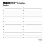
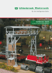
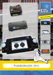
"\
l2JARNDIID-N
Steuergerät 6385
Mit dem Steuergerät 6385 kann die ARNOLD-Drehscheibe 6381
automatisch betätigt werden.
Dieses Gerät ist zum Einbau in Gleisbild-Stellpulte vorgesehen
und ist auf 24 Scheibenstellungen abgestimmt.
Ober einen drehbaren Einstellring kann eine Gleisvorwahl
getroffen werden. Die Drehscheibe fährt dann automatisch
und ohne Unterbrechung zu dem gewünschten Gleisanschluß
und verriegelt sich. Die Stellung der Drehscheibenbühne wird
gleichzeitig in das' Steuergerät zurückgemeldet. Das im Einstell ring vorgesehene Drehscheibensymbol dreht sich mit der
eigentlichen Drehscheibe mit. Es ist also auf dem Automatikschalter die jeweilige Stellung der Drehscheibe zu erkennen.
Für eine Lok-Wendung ist der Einstellring um 1800 zu drehen.
Einbau
a Mit Stichsäge oder Kreisschneider Aussparung mit 80 mm C/J
in Stellpultplatte schneiden.
b Drehscheibenzeichnung von der Karton-Inneneinlage für
Gleisbildstellpult ausschneiden und auf eine Zeichnung nach
eigener Wahl kleben.
c Befestigung mit Holzschrauben 1920 (Markierung 5 oben).
2
3
4
5
6
Bild 1: Aufsicht auf das Steuergerät mit allen wesentlichen
Merkmalen.
1 Drehbarer Einstellring
zur manuellen Betätigung.
2 Anzeigescheibe mit drehbarem Symbol für vollautomatische
Rückstellung.
3 Einstellanzeiger,
4 Einstellpunkt
weiß markiert.
im Anzeigesymbol.
5 Einbaumarke, soll immer oben sein, besonders bei Einbau
in Schräglage.
~
6 Befestigungslöcher für Holzschraube Nr. 1920.
7 Gleismarkierung auf feststehendem
eine Markierung.
Skalenrand;
alle 7,50
8 Einstellschlitz zum erstmaligen Einjustieren der Anzeigenscheibe für eine lagerichtige Stellung des Drehbühnensymbols.
9 Zeiger für Gleismarkierung.
I
8
9
7
i
Einstellen (ohne Strom!)
dEinsteilzeiger 3 in dieselbe Stellung
bühne in der Drehscheibe.
e Mit Schraubenzieher Anieigescheibe
solange drehen, bis sich Einstellpunkt
deckt.
bringen
wie
Drehrot
2 am Einstellschlitz
4 mit Einstellzeiger
8
3
schwarz
Inbetriebnahme
f Elektr. Anschluß gemäß Bild 3 herstellen. Anschluß erfolgt
an die 16 V Wechselstrombuchsen des Regeltrafos 7090.
9 Gewünschtes Gleissegment durch Verdrehen des Einstellringes 1 ansteuern, bis Einstellzeiger 3 an der gewünschten
Gleismarkierung 7 steht.
h Drehbühne setzt sich nun sofort in Bewegung, gleichzeitig
läuft die Anzeigescheibe gleichsinnig und schrittweise mit.
Wenn das gewünschte Gleissegment erreicht ist, stoppt automatisch die Drehscheibe, ebenso die Anzeigescheibe im Automatikschalter.
Die Drehscheibe ist jetzt verriegelt und kann nun mit einer
Lokomotive befahren werden.
Die Symbolscheibe hat nunmehr dieselbe Lage wie die eigentliche Drehscheibenbühne eingenommen.
Bei richtiger Justierung läuft der weiße Einstellpunkt 4 immer
dem weißmarkierten Einstellzeiger automatisch nach. Sollte
dieses Folgespiel einmal aus dem Takt kommen genügt es,
wie unter e beschrieben zu verfahren.
n1 :!!
5 4
3 2 1
Trafo 7090
b,"un
9'"u
Elektrischer Anschluß nur an 16 V Wechselstrom!
Das Steuergerät funktioniert am besten, wenn es an die volle
Spannung von 16 V Wechselstrom angeschlossen wird. Hierzu eignet sich vorzugsweise ein Trafo nach der VDE-Norm,
wie z. B. unser Großtransformator 7090.
Wenn trotzdem Störungen, z. B. unregelmäßiger Lauf, auftreten, so ist zu überprüfen, ob der Trafo durch Einschalten
zu vieler Stromverbraucher, etwa durch Beleuchtung, überlastet ist.
Bei einer eventuellen Rücksendung ins Werk zwecks Durchsicht oder Reparatur empfiehlt es sich, immer die Drehbühne
mit einzusenden. Durch Wegschieben der Klemmfeder kann
die Drehbühne vom Teller leicht abgehoben werden.
Service 6381/6385
Steuergerät 6385 und Drehscheibe 6381 sind aufeinander abgestimmt. Sollte das Steuergerät Fehlschaltungen durchführen, dann zunächst wie unter Punkt "einstellen" erklärt, eine
neue Einstellung vornehmen.
Bei einer eventuellen notwendigen Reparatur ist das Steuergerät mit der zugehörigen Drehbühne einzusenden. Die Drehbühne läßt sich aus dem Drehscheibenteller gemäß Anweisung "Drehscheibe 6381" leicht ausbauen.
~
-
-
2
"I
Selector 6385
3
Bild 3 Einbaubeispiel in ein Gleisbildstellpult
Die gewünschten Gleisabgänge sind leicht anhand der auf
dem Schalterrand erkennbaren Gleismarkierungen nach eigener Vorstellung einzuführen.
I
One can operate automatically the Arnold rapido turntable 6381 by
means of the selector 6385.
This control panel is intended for installation in a schematic track
diagram, and has 24 selector positions.
By turning a movable selector ring the desired track can be selected.
The turntable then movels automatically to that track and locks itself
in piace. At the same time the current position of the turntable is
reported back and' indicated on the control panel. The turntable symbol on the control panel automatically turns as the turntable does.
To turn a locomotive by 180' simply turn the selector 180'.
Fig.1 View of the selector with important features.
1. Movable selector ring for manual operation.
2. Report disc with movable symbol for fully automatic report.
3. Adjusting pointer marked white.
4. Adjusting point in the recording symbol.
5. Installation point, should always be at the top, especially if disc
is built into a slant diagram.
6. Holes for wood screws 1920.
7. Track markings on the fixed edge of the instrument. A marking
every 7'/z'.
: .
8. Adjusting slot for the inital adjusting of the report disc to correspond with the stage position.
9. Pointer for marking tracks.
Installation
a) Use a saw and cut a circle 3'/, inch diameter in the base plate.
b) Cut the drawing of the turntable from the inner carton of the
selector panel and paste it on the appropriate place on your
control panel.
c) Attach control panel using wood screws 1920 (marking 5 at the
top).
Adjustment (wilhout Power)
d) Adjustment pointer 3 should be brought into the same position
as the stage of the turntable.
e) Use a screw driver to turn report disc 2 on the adjusting disc
8 until adjusting point 4 covers the adjustment point 3.
Operation
f) Connect as per diagram 3. Attach to the 16 Volt outlet of the
power pack.
.
g) Turn the selector ring 1 unlil adjustment pointer 3 is at the
desired track marking 7.
h) Turntable stage will now move; at the same time the indicator
disc moves at the same speed and in the same direction. When
the preselected track segment is reached the turntable as weil
as the indicator disc stop automatically. The turntable stage is
now locked and a locomotive may move over it.
I!
The symbol disc has now reached the same position as the turntable
stage. I1 properly adjusted the white adjustment 4 automatically
lollows the adjustment pointer which is marked white. I1 during operation it should occasionally happen that it lalls out 01 line, it is
sufficient to proceed as per discription e above.
Fig. 2 Example 01 Installation Int03 Track Diagram.
The desired parking tracks are easily noticable Irom the track
markings at the edge 01 the instrument.
Fig. 3 Electrical Installation
The instrument operates best il it receives a lull 16 Volts A.C. Irom
the power pack recommended, the large rapide power pack 7080.
Service 6381/6385
The automatic pre-selector 6385 and the turntable 6381 are accorded
on each other. 11the automatic pre-selector should carry out laulty
connections, one must, lirst of all, try a new adjustment as explained
under "adiustment"
If arepair' is possib'ly necessa'ry, the automatic pre-selector with the
corresponding revolving bridge shouid be sent to our factory. The
bridge can easily be removed from the turntable-plate according to
the directions "Turntable 6381".
Appareil
automatique
6385
On peut operer automatiquement la plaque tournante Arnold rapido
6381 a I'aide de I'appareil automatique 6385.
Celui-ci est prevu pour etre incorpore dans un poste de commande
figuratif et il permet de. positionner le pont a 24 emplacements
differents.
Un disque rotatif sert a choisir la voie desiree. Le po nt tourne alors
sans arrets intermediaires jusqu'a la voie en question et se bloque
a cet endroit. Au fur et a mesure du deplacement du pont, un repetiteur se trouvant sur I'appareil automatique indique le cheminement
du pont: le symbole du po nt tourne reellement en meme temps que
lui. De cette la<;:on, il ne pose aucun probleme de savoir a lout
moment comment le po nt se trouve place. Pour virer une locomotive,
jl suffit donc de prevoir une rotation de 180'.
Fig.1
Vue de I'appareil automatique avec tous ses accessoires.
1. Disque rotatif pour commande manuelle.
2. Disque repetiteur donnant a chaque moment le positionnement
du pont.
3, Indicateur de positionnement, colon§ en blanc.
4. Point de positionnement sur le symbole du pont.
5. Repere de montage devant toujours se trouver sur le haut, surtout
dans les montages obliques.
6. Trous de fixation pour clous nO 1920.
7. Indication des voies de sortie sur le rebord fixe: un repere tous
les 7,5'.
8. Dispositif pour le premier reglage afin que I'emplacement du po nt
corresponde exactement avec celui du symbole.
9. Repere des voies.
l\IJontage
si Decouper un cercle de C/J80 mm dans la base du poste de
commande.
b) Decouper le dessin de la plaque tournante hors de I'emballage
du poste de commande et le coller sur un dessin de son propre
choix.
c) Fixer I'appareil de commande au moyen de vis 1920
(index 5 ci-dessus).
Mise en route (sans courant!)
d) Amener I'indicateur de positionnement 3 dans la meme position
que le po nt sur la plaque tournante.
s) Au moyen d'un tournevis, tourner le disque repetiteur 2 jusqu'a
ce que le point de positionnement 4 corresponde avec I'indicateu r 3.
Mise en service
I)
Effectuer le raccordement electrique d'apres la fig. 3. Prendre
le courant aux bornes de courant alternatif 16 V. du transformateur 7090.
9) Choisir la voie desiree en tournant le disque rotatif 1, jusqu'a ce
que I'indicateur 3 se trouve sur le repere 7 de la voie choisie.
h) Le po nt se met immediatement en route et ledisque repetiteur
suit pas a pas son deplacement. Lorsque la voie choisie est
atteinte, le po nt s'arrete automatiquement, de meme que le repetiteur de l'appareil automatique.
Le po nt est ainsi bloque et on peut y engager une locomotive. Le
symbole figuratif du po nt a pris la meme position que celui-ci. Lorsque le reglage a ete bien, fait, le point de positionnement 4 suit
toujpurs I'indicateur 3. 8'il devait se faire qu'a un moment donne
cere soit plus le cas, il suffiralt de refaire le reglage comme il est
indique sous la lettre e.
Fig.2 Exemple de montage dans le poste liguratif.
Les' differentes voies de sorties peuvenl eire aisemenl mises en
plac~ en se basanl sur les reperes de voies places au bord de
l'apP?reil.
Fig. 3 Exemple de raccordement electrique.
L'appareil fonctionne le mieux lorsqu'il est raccorde a des bornes
de 16 V courant alternatif. A cet effet, il est recommande d'utiliser
un transformateur construit d'apres les normes VDE, par exemple
notre gros transformateur 7090.
Service 6381/6385
Le poste de commande automatique 6385 et la plaque tournante 6381
sont accordes I'un sur I'autre. Si le poste de commande automatique
etablissait de fausses connections, I1 faut, tout d'abord, proceder a
un nouveau reglage comme explique sous le point "reglage».
Dans le cas d'une reparation eventuelle necessaire, iI faut retourner
a nos usines le poste de commande automatique avec le plateau
correspondant. Le plateau tournant se laisse facilement enlever de
la plaque tournante conformement au mode d'emploi "Plaque tournante 6381».
Made in Western Germany 1,7378
K. Arnold & Co. KG, 85 Nürnberg 1
--~
-