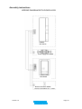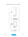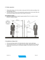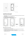
1
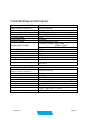
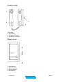
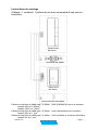
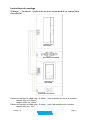
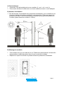
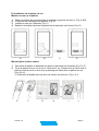
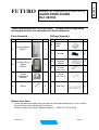
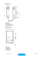
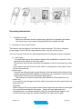
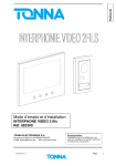
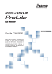
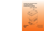
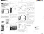
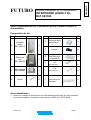
FRANCAIS
FUTURO
Mode d’emploi et d’installation
INTERPHONE AUDIO 2 fils
Réf. 683100
Avant l’installation du kit, il est ipératif de lire le mode d’emploi et
d’installation.
Composition du kit :
Ref
A
B
Description
Illustration
Combiné
audio
Réf. 683110
Platine de
rue
Réf. 683120
Qté
Ref
Description
Illustration
Qté
E
Protection pour
alimentation
1
F
Loquet
2
G
Rail DIN pour
alimentation
1
1
1
H
Vis
(Dia 4x20mm)
2
Vis
C
Alimentation
Réf. 684885
1
I
D
Screw
4
J
(Dia 3x20mm)
4
6
Cheville pour
mur plein
Avant Installation :
•
Vérifier le contenu du kit ainsi que les informations techniques. Si vous recontrez
le moindre problème, contacter notre hotline au 0033 (0) 3 26 05 28 94.
Version 1.0
Page 1
Caractéristiques techniques :
Combiné audio Réf. 683110
Dimensions
(largeur x hauteur x épaisseur)
Poids
Tension d’alimentation
Consommation
Type de câblage
Transmission voix
Sonnerie d’appel
Distance Max. & câble
Vidéo S/N Ratio
Audio S/N Ratio
Extension
Aspect Matériel
Réglage
Température de fonctionnement
Spécifications
80 ×220 ×45 mm
0.4Kg
DC18V(alimentation externe au combiné)
En veille : 1W
En fonctionnement : MAX 3W
2 fils
Full duplex
Son électronique 2 tons
Combiné / Platine 50M : 1mm2
100M : 1.5mm2
Serrure électrique / Platine 20M : 1.0mm2
50dB
40dB
Aucune
ABS
Volume sonnerie
0 ~ 40 ℃
Température de stockage
-20 ~ 60 ℃
Platine de rue
Dimensions
Spécifications
Réf. 683120
(largeur x hauteur x épaisseur)
Poids
Tension d’alimentation
Consommation
Aspect Material
Câblage
Serrure électrique compatible
Installation
Température de fonctionnement
Température de stockage
Version 1.0
90 x150 x 20 mm
0.4Kg
DC12V provenant du moniteur
Max 2W
Aluminium
Combiné : 2 fils Serrure électrique : 2 fils
Max 12VCC 0.5A
En saillie
-1 0˚C ~ 50˚C(14°F ~ 122°F)
-20˚C ~ 60˚C
Page 2
Combiné audio
4
1.Ecouteur
2. Microphone
3. Ouverture de porte
4. Volume de sonnerie
Platine de rue
1. Haut parleur
2. Porte-étiquette
3. Bouton d’appel
4. Microphone
Version 1.0
Page 3
Instructions de sécurité
1. Ne pas installer à proximité d’une source de radiation comme TV, Alimentation...
2. Ne pas démonter les modules.
3. Ne pas projeter de l’eau sur le combiné. Ne pas installer la platine de rue dans un
lieu contenant des moisissures importantes.
4. Ne pas obturer les orifices de ventilation du combiné.
5. Ne pas faire tomber ou choquer les modules.
6. Il est recommandé de déconnecter les fils du combine si le système n’est pas utilise
pendant une très longue période.
7. Ne pas placer à proximité d’une source de chaleur.
8. Ne pas placer à proximité de liquide ou d’objet contenant du liquide.
9. Ne pas couvrir.
10. Ce produit est développé pour des climats modérés. Ne pas utiliser dans des lieux
à fort taux d’humidité, très poussiéreux ou sales.
11. Pour démonter le combine du mur, éteindre l’appareil (bouton raccroché), couper
l’alimentation électrique puis déconnecter les fils.
Précautions
1. Ne pas installer la platine de rue face au soleil ou en direction d’une source
lumineuse importante.
2. Ne pas installer la platine de rue dans un endroit d’extrême salissure ou de
moisissure.
3. Ne pas installer à proximité d’élément oxydant, acide , ammoniaque ou gaz nocif
et dangereux
4. L’objectif de la camera doit rester propre.
5. Avant la mise en service de l’installation, vérifier que les câbles sont correctement
connectés.
Version 1.0
Page 4
Instructions de montage
Câblage : 1 combiné / 1 platine de rue avec commande d’une serrure
électrique
Combiné audio
Réf. 683110
Alimentation Réf. 684885
Platine de rue
Réf. 683120
Serrure électrique 12Vcc 500mA
Distance et section de câble maxi. À utiliser entre la platine de rue et le moniteur :
- Jusqu’à 25m en 0,65mm2
- Jusqu’à 100m en 1,5mm2
Distance et section de câble maxi. À utiliser entre l’alimentation et le moniteur :
Jusqu’à 20m en 1 mm2
Distance et section de câble maxi. À utiliser entre la platine et la serrure électrique :
Jusqu’à 5m en 1 mm2
Version 1.0
Page 5
Instructions de montage
Câblage : 1 combiné / 1 platine de rue avec commande d’un contact libre
de potentiel
Combiné audio
Réf. 683110
Alimentation Réf. 684885
Platine de rue
Réf. 683120
Dry Contact
Contact libre de potentiel
Distance et section de câble maxi. À utiliser entre la platine de rue et le moniteur :
- Jusqu’à 25m en 0,65mm2
- Jusqu’à 100m en 1,5mm2
Distance et section de câble maxi. À utiliser entre l’alimentation et le moniteur :
Jusqu’à 20m en 1 mm2
Version 1.0
Page 6
A) Raccordement
1. Connecter 2 fils de la platine de rue au moniteur (L- sur L- et L+ sur L+)
2. Prenez soin d’insérer le câble avec une force modérée et avec un outil adéquat.
B) Hauteur d’installation
1. Afin de favoriser l’accessibilité aux personnes handicapées, nous conseillons que
le bouton d’appel de la platine soit situé à une hauteur de 130cm par rapport au
niveau du sol. Nous vous recommandons la même hauteur pour les boutons du
Combiné (partie basse du moniteur à 128cm).
B) Montage du combiné
1.
2.
Fixer la base sur le mur à l’aide des 4 vis. Positionner judicieusement la base afin
de permettre au câble de passer dans le trou au centre de la base.
Replacer le capot sur la base en prenant toutes les précautions nécessaire.
Version 1.0
Page 7
D) Installation de la platine de rue
Mettre un nom sur la platine.
1)
2)
3)
4)
Retirer la fenêtre du porte-étiquette en pressant à gauche de celui-ci. (Fig. A & B)
L’étiquette est maintenant accessible. (Fig. C)
Indiquer le nom sur l’étiquette (Fig. C)
Replacer la fenêtre dans sont logement en la ramenant vers l’avant (Fig. D)
A
B
C
D
Mounting the outdoor station
1) Démonter la façade en dévissant les deux vis situées sous la platine (Fig. E & F)
2) Fixer la platine de rue sur le mur à l’aide des 2 vis. Prenez soin de faire venir le
câble à l’endroit exact où se trouve le passage de câble dans la platine de rue
(Fig. G & H)
3) Refermer la façade avec les deux vis situées en dessous. (Fig. I et J)
E
Version 1.0
F
G
H
I
J
Page 8
Fonctionnement
1.
Lors d’un appel :
Quand le bouton d’appel de la platine est pressé, le moniteur sonne. Si vous
désirez parler, prenez le combiné et parlez.
2. Ouverture de porte
Pour ouvrir la porte, il suffit d’appuyer sur le bouton d’ouverture de porte lors de la
communication.
La platine de rue est équipée de deux sorties de commande activées en même
temps.
- Sortie 12V 500mA pour commander une serrure électrique
- Sortie contact libre de potentiel pour commander un portail motorisé
Vous pouvez ainsi commander un portail motorisé ou une serrure électrique sans
ajouter de matériel.
Lors de l’appuie sur bouton d’ouverture de porte, les 2 sorties sont actives en
même temps mais nous vous conseillons de n’utiliser qu’une sortie à la fois afin
d’être garantie d’un fonctionnement optimal.
Précaution et Maintenance
Ne pas installer près de source de chaleur ou de froid. Les températures
importantes ou très basses peuvent endommager les composants et peut altérer
certains plastiques ou causer des mal fonction.
Les court-circuit peuvent provoquer des dommages irréversible sur le circuit
électronique.
Ne pas stocker ou utiliser dans des lieux poussiéreux ou insalubres. Les
composants peuvent s’altérer plus rapidement.
Ne pas utiliser de produits chimiques, de solvants ou de détergents. Pour
nettoyer, passer uniquement un chiffon très peu humide.
Recherche de pannes
No
Problème
Point à vérifier
1
Pas d’alimentation
Vérifier la connexion de l’alimentation.
2
L’alimentation est bonne Vérifier la polarité des 2 fils entre la platine et le
mais il n’y a pas de son.
combiné.
Vérifier la continuité des câbles.
4
La sonnerie est trop
faible ou inexistante
Version 1.0
Vérifier le réglage de sonnerie du combiné
Page 9
Protection de l’environnement
•
Ne pas jeter dans une poubelle domestique. Utiliser la filière du
recyclage.
Version 1.0
Page 10
Safety & Operating Instructions
AUDIO DOOR PHONE
Réf. 683100
These instructions are for your safety. Please read through them
thoroughly before use and retain for future reference.
Parts Supplied
Ref
Description
Fittings Supplied
Illustration
Qty
Ref Description
E
A
B
Indoor Monitor
683110
Outdoor Entry
Panel
683120
Illustration
Power
cover
Qty
1
1
F
Locker
2
G
Bracket
Holder
1
1
H
Screw
(Dia 4x20mm)
2
C
Power
Transformer
684885
1
I
(Dia 3x20mm)
4
D
Screw
4
J
Wall Plug
6
Screw
Before You Start
•
Check the pack and make sure you have all of the part listed above. If not, contact
your local store who will be able to help you.
Please, contact us hotline Telephon Number : 0033 (0) 3 26 05 28 94.
Version 1.0
Page 11
ENGLISH
FUTURO
Technical Characteristics
Indoor Unit(683110)
Dimensions
Weight
Input Power
Power Consumption
Connecting System
Voice transmition
Call sound
Max. Distance & wiring
Video S/N Ratio
Audio S/N Ratio
Function
Aspect Material
Users Control
Operating Temperature
Specifications
80[W] ×220[H] ×45[D] mm
0.4Kg
DC18V(external Power Supply)
Idle mode:1W
Operating: MAX 3W
2 wires
Full duplex two way communication
Chime sound 2stroke(When call button
pushed)
Indoor Unit to Entry Panel
50M:1.0mm2 wire 100M:1.5mm2 wire
Door Lock to Entry Panel
20M:1.0mm2
50dB
40dB
1.Door open
ABS
Volume
0 ~ 40 ℃
Storage Temperature
-20 ~ 60 ℃
Outdoor Unit(683120)
Dimensions
Weight
Input Power
Power Consumption
Aspect Material
Wiring
Specifications
90[W] x150[H] x 20 [D] mm
0.4Kg
DC12V from monitor
Max 2W
Aluminium
Handset:2wires Door lock:2Wires
2 terminals with DC power output max
12V 0.5A
Surface mount
Door lock
Mounting type
Operating Temperature
Storage Temperature
Version 1.0
-1 0˚C ~ 50˚C(14°F ~ 122°F)
-20˚C ~ 60˚C
Page 12
Indoor unit
4
1.Speaker
2. Microphone
3. Door Open button
4. Volume control
Outdoor unit
1. Speaker
2. Name Plate
3. Call Button
4. Microphone
Version 1.0
Page 13
Safety Instructions
2. Do not install near other electronic equipment such as computers, TV, video
recorder as this may cause radiated interference to the unit.
2. Do not disassemble the unit.
3. Do not spray water on the indoor unit. Do not keep the outdoor unit where it will be
exposed to extreme moisture.
4. Do not overload mains wall outlets or extension cords.
5. Do not drop or shock the unit.
6. Remove the power cord from the wall socket when unit is not used for long periods.
7. Do not place any naked flames (e.g. lighted candles) on the apparatus.
8. Do not place objects filled with water (e.g. vases) on the apparatus.
9. Do not cover the ventilation holes with clothing, paper, curtains etc.
10. This apparatus is designed for moderate climates. Do not use in high humidity,
dusty or dirty areas.
11. To disconnect or isolate the unit, switch off at the socket or remove plug from wall
socket. Please ensure the plug and socket is easily accessible.
Warnings
1. Do not install the outdoor unit where it will be exposed to direct sunlight or any
strong reflected light.
2. Do not install the outdoor unit where it will be subjected to extremes of dust or
moisture.
3. Do not install the outdoor unit where it will be exposed to rain.
4. Do not install near acid oxides, ammonia, or any harmful gas (it might cause
malfunction).
5. Check cables are connected correctly and outdoor entry panel unit is firmly
installed.
Version 1.0
Page 14
Assembly instructions
WIRING DIAGRAM WITH DOOR LOCK
Handset
Ref. 683110
Power supply Ref. 684885
Outdoor station
Ref. 683120
Electric lock 12Vcc 500mA
Version 1.0
Page 15
WIRING DIAGRAM WITH GATE DRY CONTACT
Handset
Ref. 683110
Power supply Ref. 684885
Outdoor station
Ref. 683120
Dry Contact
Dry contact for open gate
Version 1.0
Page 16
C) Cable connection
3.
4.
Connect the indoor unit to the outdoor entry panel with the cable according to the
wiring diagram below.
Carefully insert the wires to the terminal by pressing down the terminal flap with
any small tool taking care that the 2 bare wires do not touch.
B) Installation height
2. Recommended installation height is approximately 140cm for monitor unit and
150cm for outdoor camera.
C) Installation of indoor Unit
3.
4.
Fix the indoor base plastic in the best place by using 4 screws and plugs.
Carefully place the door cover against the base plastic and gently push down the
indoor unit so that the pins on the bracket engage in the slots on the rear of the
indoor unit.
Version 1.0
Page 17
D) Installation of outdoor station
Add the name to the nameplate
1) Remove the cover of the name plate by pressing the left hand side of the block.
(Fig. A & B)
2) The name plate is now accessible (Fig. C)
3) Mark your name on the plate (Fig. C)
4) Place the button block back to the panel (Fig. D)
A
B
C
D
Mounting the outdoor station
1) Remove the front cover (Fig. E & F)
2) Mount the outdoor unit on the wall by using 2 mounting screws and wall plugs.
(Adjust the camera angle if necessary.)(Fig. G & H)
3) Replace the front cover and security it by replacing the 2 screws at the bottom of
the camera. (Fig. I & J)
Version 1.0
Page 18
E
F
G
H
I
J
Operating Instructions
1.
Activation of units
When the call button on the outdoor entry panel unit is pressed, the indoor
unit chime rings .If you want to talk,please lift the handset and talk.
3. Activation of “door open” button
This feature can be utilized in two kinds of output terminals. The first is using the
power supply 12volt 500mA output and the other is by dry contact output.
You can use one of the two for optimal performance for selected output connection.
a) Door open:
If an electrical lock or door strike is added to the installation, connect it to the
terminals at the bottom of the entry panel.
This function can only be used when the handset is off the hook from the indoor
unit.
If you want to open the door to let the caller in, just press the “door open” button
on the indoor monitor.
b) Gate open:
Connect the automatic gate opener directly to the terminals at the bottom of the
outdoor entry panel which supplies a current-free “dry” contact to connect to the
“push button” control of your automatic gate opener.
This function can only be used when the handset is off the hook from the
indoor unit.
If you want to open the gate to let the caller in,just press the door open button on
the indoor unit.
Reminder:
When using the Door open button when both connections open door or open gate
are connected touching the Door open button will open gate and door
simultaneously. It is recommended to follow the provided wiring diagram and
connect only one output for optimal connection for open door or gate.
Version 1.0
Page 19
Care and Maintenance
Do not store in hot or cold areas. Extreme hot or cold temperatures can shorten
the life of electronic devices and can distort/melt certain plastics or may cause
malfunction.
Dropping can result in failure to operate. Circuit boards can crack and may not
survive the impact.
Do not use or store in areas of high levels of dirt or dust. The electronics may be
contaminated. Any moving parts will wear prematurely.
Do not use harsh chemicals, cleaning solvents or strong detergents. To clean,
wipe with a damp cloth from time to time.
Troubleshooting
No
Problem
Check point
1
No power
Is the power supply connected correctly?
2
Power is on, but no
sound from outdoor
entry panel
Is the cable firmly connected between the
indoor unit and the entry panel?
Is the polarity of wires correct between the
outdoor entry panel unit and indoor unit?
4
Chime sound is too low
Adjust the volume control
Environmental Protection
•
Waste electrical products should not be disposed of with household
waste. Please recycle where facilities exist. Check with your Local
Authority or retailer for recycling advice.
Version 1.0
Page 20