1
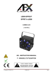
SAMOURAÏ 200
LYRE LASER VERT DMX
DMX GREEN LASER MOVING HEAD
MODE D’EMPLOI
USER MANUAL
FRANÇAIS
L’appareil SAMOURAÏ 200 est spécialement conçu pour une utilisation sur scène, en discothèque. Il produit un laser vert qui affiche 2 logos en
même temps ( angle, rotation et déplacement réglable séparément ) soit au rythme de la musique ( par un micro intégré ) ou soit en utilisant un
contrôleur DMX.
DESCRIPTION
1. SORTIE LASER
Ce trou est la sortie du laser. N’obstruez jamais ce trou sinon le laser ne sera pas affiché.
2. PANNEAU DE CONTROLE DMX
Ces 4 boutons vous permettent de modifier l’adresse DMX correspondant au canaux PAN et TILT, d’effectuez une test de rotation PAN et
TILT et enfin d’effectuez un reset.
Les DIP contrôle l’adresse DMX de l’appareil et le panneau de contrôle permet de choisir les adresses DMX des canaux PAN, TILT. Si
vous entrez deux adresses différentes ( par exemple adresse DIP =2 et adresse panneau de contrôle = 1 ), certains canaux ne
fonctionneront plus normalement. C’est pour cela que vous nous conseillons d’utiliser les mêmes adresses pour les DIP et le panneau de
contrôle. Par exemple, si vous entrez l’adresse DMX DIP = 42, il est préférable d’entrer l’adresse DMX panneau de contrôle = 42
FUNC :
Appuyez sur cette touche une ou plusieurs fois pour entrer dans le menu du SAMOURAI 200.
Une pression : l’afficheur des adresses clignote ( utilisez les touches UP / DOWN pour sélectionner l’adresse DMX )
Deux pressions : L’afficheur vous indique Pan ( rotation horizontale ). Appuyez sur enter pour faire une rotation PAN
( test de bon fonctionnement ).
Trois pressions : L’afficheur vous indique Tilt ( rotation verticale ). Appuyez sur enter pour faire une rotation Tilt
( test de bon fonctionnement ).
Quatre pressions : : L’afficheur vous indique Colo ( couleur ).
Cinq pressions : L’afficheur vous indique Reset. Appuyez sur enter pour effectuer un repositionnement des moteurs
Note : Le logiciel interne gérant le est commun à plusieurs lyres. C’est pour cela que vous avez accès au mode Colo mais que ce
dernier ne fonctionnent pas.
UP / DOWN : Utilisez ces touches pour modifier la valeur de l’adresse DMX
ENTER : Appuyez sur cette touche pour valider une valeur
3. DIP SWITCH
Ce bornier de DIP vous permet de sélectionner l’adresse DMX du NIPPON 120 ( DIP 1 à 9 ) et le mode de fonctionnement du NIPPON 120
( DIP 10 (sound) sur OFF = mode DMX, DIP 10(sound) sur ON = mode musical )
La sélection de l’adresse DMX se fait à partir du tableau suivant :
ADRESSE
01
02
03
04
05
06
07
08
---509
510
511
1 = ON, 0 = OFF
SWITCH DIP
987654321
000000001
000000010
000000011
000000100
000000101
000000110
000000111
000001000
-------------------111111101
111111110
111111111
4. SORTIE DMX
Connectez cette sortie sur l’entrée DMX d’un autre SAMOURAÏ 200 afin de contrôler plusieurs SAMOURAÏ 200 avec un seul contrôleur
DMX ( l’adressage DMX permettra de choisir si tout les SAMOURAÏ 200 travaillent ensemble ou séparément )
5. ENTREE DMX
Après avoir connecté la câble XLR sur votre console DMX, connectez l’autre extrémité du câble sur cette prise
Note: le branchement des entrées et sorties DMX est le suivant : Patte 1 = masse, Patte 2 = point froid (-) et Patte 3 = Point chaud (+)
6. CONNECTEUR SECTEUR + FUSIBLE
Connectez votre câble secteur dans cette prise. Avant la mise en marche de la table, branchez le cordon d’alimentation dans toute prise
secteur. Avant cela, toujours s’assurer que le voltage est correct.
Le fusible est intégré à la prise. Il permet d’éviter à votre amplificateur tout problème d’alimentation. Si l’ampli est en marche et que rien ne
s’allume, il faut vérifier le compartiment à fusibles. Si le fusible est défectueux, il faut le remplacer par un nouveau de même taille et de
même valeur
7. INTERRUPTEUR ON/OFF
Positionnez cet interrupteur sur ON pour allumez l’appareil. Positionnez le sur OFF pour l’éteindre.
8. REGLAGE PROPORTION HORIZONTALE
Ce petit potentiomètre permet d’ajuster la proportion horizontale ( la largeur ) du logo affiché
9. REGLAGE PROPORTION VERTICALE
Ce petit potentiomètre permet d’ajuster la proportion verticale ( la hauteur) du logo affiché
INSTALLATION
-
Avant de connecter l’appareil au secteur, vérifiez bien que la tension du secteur et la tension d’alimentation de l’appareil soient
compatibles ( 230V )
Attention de ne pas surchargez les multiprises auxquelles vous allez brancher les appareils
Pour l’installation demandez l’aide d’un professionnel
Positionnez le faisceau de tel sorte qu’il ne soit pas dirigé directement dans le yeux d’une personne.
-
La chaleur dégagée par l’appareil doit pouvoir être évacuée par une circulation d’air adaptée. En aucun cas, les parties de ventilation
ne doivent être obstruées par quelque objet que ce soit.
-
En dessous de l’appareil se trouve des trous afin de faire passer les fil de sécurité. Pour être en accord avec la loi, ces fils doivent
pouvoir supporter 10 fois le poids de l’appareil
CONSEIL D’UTILISATION :
-
-
Cet appareil n’est conçu que pour une utilisation en intérieur; protégez-le de l’humidité et de la chaleur (température ambiante
autorisée 10–35°C).
Pendant le fonctionnement, l’appareil chauffe. Pour éviter toute brûlure, ne touchez jamais l’appareil pendant son fonctionnement. De
même, une fois éteint, laissez-le refroidir quelques minutes avant de le toucher.
La chaleur dégagée par l’appareil doit pouvoir être évacuée par une circulation d’air adaptée. En aucun cas, les parties de ventilation
ne doivent être obstruées par quelque objet que ce soit.
Ne faites rien tomber dans les parties de ventilation et n’y introduisez rien, vous pourriez vous électrocuter!
Ne faites pas fonctionner l’appareil ou débranchez le immédiatement lorsque:
o
des dommages apparaissent sur l’appareil ou sur le cordon secteur.
o
après une chute ou un cas similaire, vous avez un doute sur l’état de l’appareil.
o
des dysfonctionnements apparaissent.
L’appareil est alimenté par une tension très dangereuse en 220V~240V. En cas de mauvaise manipulation, vous pourriez subir une
décharge électrique mortelle. Faites toujours appel à un technicien spécialisé pour effectuer les réparations.
Seul le constructeur ou un technicien habilité peut remplacer le cordon secteur.
Ne le débranchez jamais en tirant directement sur le cordon secteur.
Nous déclinons toute responsabilité en cas de dommage si l’appareil est utilisé dans un but autre que celui pour lequel il a été conçu,
s’il n’est pas correctement monté, utilisé ou réparé par un technicien habilité.
Pour le nettoyer, utilisez un chiffon sec et doux, en aucun cas, de produits chimiques ou d’eau.
Ne dirigez pas le rayon laser directement sur une personne et ne regardez pas le laser directement sinon vous risquez de vous
abîmez les yeux.
FONCTIONNEMENT MODE MUSICALE:
Reliez le SAMOURAÏ 200 au secteur (220V~240V/ 50Hz-60Hz) puis positionnez l’interrupteur on/off sur la position ON
Sélectionnez le mode musical sur le bornier DIP ( DIP 10(sound) = ON )
Réglez le volume souhaité sur le système audio.
Si l’appareil ne réagit pas, augmentez légèrement le volume du système audio
Pour éteindre l’appareil, positionnez l’interrupteur on/off sur la position OFF et débranchez la câble secteur pour éteindre l’appareil.
NOTE : En mode musicale, les moteurs PAN et TILT ne varient pas en fonction de la musique. Si vous voulez modifier la position PAN et
TILT, vous devez utiliser une console DMX ( canaux 9, 10 et 11 si l’adresse DMX (DIP) est 1 et si l’adresse DMX ( panneau de contrôle )
est 1 ).
FONCTIONNEMENT DMX :
-
Reliez le SAMOURAÏ 200 au secteur (220V~/ 50Hz).
Connectez l’entrée DMX du SAMOURAÏ 200 à la sortie DMX de la console ( utilisez un câble XLR-XLR )
Si vous voulez utilisez plusieurs SAMOURAÏ 200 ( ou appareil DMX ) en utilisant une seule console DMX, connectez vos appareil
comme indiqué sur le dessin ci-dessous
-
Sélectionnez le mode DMX en positionnant le DIP 10(sound) sur OFF ( bonier DIP )
Utilisez votre console DMX pour contrôler les différents canaux du SAMOURAÏ 200
Le mode DMX a été inventé pour simplifier la commande des jeux de lumière
Vos différents appareils DMX sont constitués en canaux DMX. Vous devez ajuster l’adresse DMX en fonction du nombre de canaux de
l’appareil. Le nombre de potentiomètre de commande dépend du nombre de canaux de l’appareil ( Ex : si votre appareil à 4 canaux, 4
potentiomètres de la console contrôleront les canaux DMX de l’appareil. )
Pour simplifier votre compréhension, je vais vous donner plusieurs exemples :
er
1 exemple :
Vous voulez contrôler un seul appareil à partir de votre console DMX. Vous devez alors régler l’adresse 1 sur votre appareil de lumière DMX.
Le nombre de potentiomètre de commande dépend du nombre de canaux de l’appareil. Dans le cas du SAMOURAÏ 200, ce sont les 20
premiers potentiomètres de la console qui contrôleront le SAMOURAÏ 200.
2eme exemple :
Vous voulez contrôler deux appareils DMX, les deux appareils ont 20 canaux DMX chacun ( comme le SAMOURAÏ 200 ).
Vous devez alors régler le premier appareil DMX à l’adresse 1 et le deuxième à l’adresse 21.
Les 20 premiers potentiomètres de votre console contrôleront les canaux du premier appareil et les 20 potentiomètres suivants contrôleront les
canaux du deuxième appareil.
3eme exemple :
Vous voulez contrôler deux appareils DMX, un appareil a 6 canaux et le deuxième a 8 canaux .
Vous devez alors régler le premier appareil DMX à l’adresse 1 et le deuxième à l’adresse 7.
Les 6 premiers potentiomètres de votre console contrôleront les canaux du premier appareil et les 8 potentiomètres suivants contrôleront les
canaux du deuxième appareil.
4eme exemple :
Vous voulez contrôler trois appareils DMX, un appareil a 6 canaux, le deuxième a 8 canaux et le troisième a 10 canaux.
Vous devez alors régler le premier appareil DMX à l’adresse 1, le deuxième à l’adresse 7 et le troisième appareil a l’adresse 15.
Les 6 premiers potentiomètres de votre console contrôleront les canaux du premier appareil, les 8 potentiomètres suivants contrôleront les
canaux du deuxième appareil et enfin les 10 potentiomètres suivants contrôleront les canaux du troisième appareil.
RAPPEL : En sortie du dernier SAMOURAÏ 200 ( ou dernier appareil DMX de la chaîne ), reliez la patte 2 et la patte 3 de la prise XLR en
utilisant une résistance de 120 Ohms. Cela peut éviter un phénomène de clignotement du signal DMX pendant la transmission.
Le SAMOURAÏ 200 possède 20 canaux DMX et peut affiché deux logos entièrement indépendant l’un de l’autre. En mode DMX, chaque canal
sera contrôlé par un potentiomètre de votre console de lumière. Les 8 premiers canaux sont utilisés pour le logo 1, les trois canaux suivants
sont utilisés pour les rotations PAN et TILT et les 9 canaux restants servent au logo 2.
Si votre SAMOURAÏ 200 est réglé sur l’adresse 1, la configuration des potentiomètres sera la suivante :
Potentiomètre 1 → Canal 1 ( logo 1 )
Potentiomètre 2 → Canal 2 ( logo 1 )
Potentiomètre 3 → Canal 3 ( logo 1 )
Potentiomètre 4 → Canal 4 ( logo 1 )
Potentiomètre 5 → Canal 5 ( logo 1 )
Potentiomètre 6 → Canal 6 ( logo 1 )
Potentiomètre 7 → Canal 7 ( logo 1 )
Potentiomètre 8 → Canal 8 ( logo 1 )
Potentiomètre 9 → Canal 9 ( Rotation PAN )
Potentiomètre 10 → Canal 10 ( Rotation TILT )
Potentiomètre 11 → Canal 11 ( réglage fin PAN et TILT )
Potentiomètre 12 → Canal 12 ( logo 2 )
Potentiomètre 13 → Canal 13 ( logo 2 )
Potentiomètre 14 → Canal 14 ( logo 2 )
Potentiomètre 15 → Canal 15 ( logo 2 )
Potentiomètre 16 → Canal 16 ( logo 2 )
Potentiomètre 17 → Canal 17 ( logo 2 )
Potentiomètre 18 → Canal 18 ( logo 2 )
Potentiomètre 19 → Canal 19 ( logo 2 )
Potentiomètre 20 → Canal 20 ( logo 2 )
Le canal 1 ( logo 1 ) :
Le canal 1 a 3 fonctions :
Arrêt ( stop ) : Sur la position la plus basse du potentiomètre, le SAMOURAÏ 200 est en mode arrêt. C’est à dire que le SAMOURAÏ
200ne projette aucun motif et le laser est éteint.
Départ 1 ( start ) : Le cran suivant, le SAMOURAÏ 200 allume le laser et affiche un motif.
Mode point 1 ( dotting ) : le logo sera affiché sous forme de point.
Départ 2 ( start ) : Le cran suivant, le SAMOURAI 200 allume le laser et affiche un motif. Le logiciel interne étant commun à plusieurs
appareils ( ex : Nippon 120 ), ce mode ne fonctionne pas dans le SAMOURAI 200
Mode point 2 ( dotting ) : le logo sera affiché sous forme de point. Le logiciel interne étant commun à plusieurs appareils ( ex : Nippon
120 ), ce mode ne fonctionne pas dans le SAMOURAI 200.
Le canal 2 ( logo 1 ) :
Le canal 2 n’a qu’une seule fonction : Il vous permet de sélectionner le motif que vous voulez afficher. Vous avez le chois entre 256 motifs.
Note : certains motifs qui se suivent peuvent former le mouvement d’un personnage comme un oiseau qui vole ou une personne qui
court, d’autres motifs sont des textes comme 0, 1, 2, 3...
Le canal 3 ( logo 1 ) :
Le canal 3 a 2 fonctions :
Angle d’affichage ( gobo angle ) : Vous pouvez déterminer l’angle d’affichage du gobo. L’angle dépend de la position du
potentiomètre.
Rotation anti-horaire ( unclockwise rotate ) : vous pouvez lancer la rotation du gobo ( sur lui-même ) dans le sens anti-horaire. La
vitesse de rotation dépend de la position du potentiomètre.
Le canal 4 ( logo 1 ) :
Le canal 4 a 2 fonctions :
Modification proportion X ( left-right zoom ) : Vous pouvez ajuster la proportion X du motif ( ajustement de 1 à –1 ). C’est à dire que le
motif va s’aplatir verticalement jusqu’à ce que le motif soit un trait ( ajustement 0 ) et pouvez rétablir le motif mais inversé
verticalement ( ajustement –1 ). L’ajustement dépend de la position du potentiomètre
Modification automatique proportion X ( left-right roll ) : Vous pouvez lancer une séquence qui modifiera la proportion X du motif
progressivement. Cette séquence peut faire penser à une rotation suivant l’axe verticale du motif. La vitesse de rotation dépend de la
position du potentiomètre.
Le canal 5 ( logo 1 ) :
Le canal 5 a 2 fonctions :
Modification proportion Y ( up-down zoom ) : Vous pouvez ajuster la proportion Y du motif ( ajustement de 1 à –1 ). C’est à dire que le
motif va s’aplatir horizontalement jusqu’à ce que le motif soit un trait ( ajustement 0 ) et pouvez rétablir le motif mais inversé
horizontalement ( ajustement –1 ). L’ajustement dépend de la position du potentiomètre
Modification automatique proportion Y ( up-Down roll ) : Vous pouvez lancer une séquence qui modifiera la proportion Y du motif
progressivement. Cette séquence peut faire penser à une rotation suivant l’axe horizontale du motif. La vitesse de rotation dépend de
la position du potentiomètre.
Le canal 6 ( logo 1 ) :
Le canal 6 a 2 fonctions :
Déplacement horizontale : Vous pouvez effectuer une translation horizontale du motif. Au départ, le logo se déplace vers la droite
puis rebondit pour revenir vers la gauche ( mais inversé ). Lorsqu’il arrive complètement à gauche, il repart vers la droite . La vitesse
de déplacement dépend de la position du potentiomètre.
Déplacement vertical : Vous pouvez effectuer une translation verticale du motif. Au départ, le logo se déplace vers le haut puis
rebondit pour revenir vers le bas ( mais inversé ). Lorsqu’il arrive complètement en bas, il repart vers le haut . La vitesse de
déplacement dépend de la position du potentiomètre.
Le canal 7 ( logo 1 ) :
Le canal 7 a 1 fonction1 :
Ecriture humaine automatique ( speed drax ) : le SAMOURAÏ 200 simule l’écriture humaine ( le motif s’affiche progressivement ).
vous pouvez lancer une séquence automatique simulant l’écriture humaine du motif. Le logo sera affiché puis effacé
progressivement. La vitesse d’écriture dépend de la position du potentiomètre.
Le canal 8 ( logo 1 ) :
Le canal 8 a 2 fonctions :
Strobe : le logo va clignoter. La vitesse de clignotement dépend de la position du potentiomètre ( plus le logo clignote vite, plus les
points formant le logo ressorte )
Mode pointillé : Le logo est affiché en pointillé. La taille des pointillés dépend de la position du potentiomètre.
Note : Pour le visualiser le mode pointillé, vous devez positionner le canal 1 sur le mode point 1
Le canal 9 :
Le canal 9 est utilisé pour la rotation PAN. L’angle de rotation dépend de la position du potentiomètre.
Le canal 10 :
Le canal 9 est utilisé pour la rotation TILT. L’angle de rotation dépend de la position du potentiomètre.
Le canal 11 :
Le canal 11 est utilisé pour ajuster la précision des mouvements PAN et TILT. Plus la valeur du potentiomètre est grande, plus le réglage des
mouvements PAN et TILT seront précis.
Le canal 12 ( logo 2 ) :
Le canal 12 a 3 fonctions :
Arrêt ( stop ) : Sur la position la plus basse du potentiomètre, le SAMOURAÏ 200 est en mode arrêt. C’est à dire que le SAMOURAÏ
200ne projette aucun motif et le laser est éteint.
Départ 1 ( start ) : Le cran suivant, le SAMOURAÏ 200 allume le laser et affiche un motif.
Mode point 1 ( dotting ) : le logo sera affiché sous forme de point.
Départ 2 ( start ) : Le cran suivant, le SAMOURAI 200 allume le laser et affiche un motif. Le logiciel interne étant commun à plusieurs
appareils ( ex : Nippon 120 ), ce mode ne fonctionne pas dans le SAMOURAI 200
Mode point 2 ( dotting ) : le logo sera affiché sous forme de point. Le logiciel interne étant commun à plusieurs appareils ( ex : Nippon
120 ), ce mode ne fonctionne pas dans le SAMOURAI 200.
Le canal 13 ( logo 2 ) :
Le canal 13 n’a qu’une seule fonction : Il vous permet de sélectionner le motif que vous voulez afficher. Vous avez le chois entre 256 motifs.
Note : certains motifs qui se suivent peuvent former le mouvement d’un personnage comme un oiseau qui vole ou une personne qui
court, d’autres motifs sont des textes comme 0, 1, 2, 3...
Le canal 14 ( logo 2 ) :
Le canal 14 a 2 fonctions :
Angle d’affichage ( gobo angle ) : Vous pouvez déterminer l’angle d’affichage du gobo. L’angle dépend de la position du
potentiomètre.
Rotation anti-horaire ( unclockwise rotate ) : vous pouvez lancer la rotation du gobo ( sur lui-même ) dans le sens anti-horaire. La
vitesse de rotation dépend de la position du potentiomètre.
Le canal 15 ( logo 2 ) :
Le canal 15 a 2 fonctions :
Modification proportion X ( left-right zoom ) : Vous pouvez ajuster la proportion X du motif ( ajustement de 1 à –1 ). C’est à dire que le
motif va s’aplatir verticalement jusqu’à ce que le motif soit un trait ( ajustement 0 ) et pouvez rétablir le motif mais inversé
verticalement ( ajustement –1 ). L’ajustement dépend de la position du potentiomètre
Modification automatique proportion X ( left-right roll ) : Vous pouvez lancer une séquence qui modifiera la proportion X du motif
progressivement. Cette séquence peut faire penser à une rotation suivant l’axe verticale du motif. La vitesse de rotation dépend de la
position du potentiomètre.
Le canal 16 ( logo 2 ) :
Le canal 16 a 2 fonctions :
Modification proportion Y ( up-down zoom ) : Vous pouvez ajuster la proportion Y du motif ( ajustement de 1 à –1 ). C’est à dire que le
motif va s’aplatir horizontalement jusqu’à ce que le motif soit un trait ( ajustement 0 ) et pouvez rétablir le motif mais inversé
horizontalement ( ajustement –1 ). L’ajustement dépend de la position du potentiomètre
Modification automatique proportion Y ( up-Down roll ) : Vous pouvez lancer une séquence qui modifiera la proportion Y du motif
progressivement. Cette séquence peut faire penser à une rotation suivant l’axe horizontale du motif. La vitesse de rotation dépend de
la position du potentiomètre.
Le canal 17 ( logo 2 ) :
Le canal 17 a 2 fonctions :
Déplacement horizontale : Vous pouvez effectuer une translation horizontale du motif. Au départ, le logo se déplace vers la droite
puis rebondit pour revenir vers la gauche ( mais inversé ). Lorsqu’il arrive complètement à gauche, il repart vers la droite . La vitesse
de déplacement dépend de la position du potentiomètre.
Déplacement verticale : Vous pouvez effectuer une translation verticale du motif. Au départ, le logo se déplace vers le haut puis
rebondit pour revenir vers le bas ( mais inversé ). Lorsqu’il arrive complètement en bas, il repart vers le haut . La vitesse de
déplacement dépend de la position du potentiomètre.
Le canal 18 ( logo 2 ) :
Le canal 18 a 1 fonction1 :
Ecriture humaine automatique ( speed drax ) : le SAMOURAÏ 200 simule l’écriture humaine ( le motif s’affiche progressivement ).
vous pouvez lancer une séquence automatique simulant l’écriture humaine du motif. Le logo sera affiché puis effacé
progressivement. La vitesse d’écriture dépend de la position du potentiomètre.
Le canal 19 ( logo 2 ) :
Le canal 19 a 2 fonctions :
Strobe : le logo va clignoter. La vitesse de clignotement dépend de la position du potentiomètre ( plus le logo clignote vite, plus les
points formant le logo ressorte )
Mode pointillé : Le logo est affiché en pointillé. La taille des pointillés dépend de la position du potentiomètre.
Note : Pour le visualiser le mode pointillé, vous devez positionner le canal 12 sur le mode point 1
Canal 20 ( logo 2 ) :
Le canal 20 est utilisé pour ajuster la taille du logo 2. La taille du logo dépend de la position du potentiomètre.
CARACTERISTIQUES TECHNIQUES :
Alimentation :
Laser :
Puissance laser :
220V~240 / 50Hz-60Hz
2 x Vert
200mW
CONDITIONS DE GARANTIE :
Les équipements LYT-OR sont couverts par une garantie d’1 an pièces et main d’œuvre.
Les principes suivants s’appliquent à partir du moment où l’appareil quitte nos usines.
La facture de mise à la consommation fera foi de date de départ de la garantie, dans la mesure ou celle-ci n’excède pas 12 mois par rapport à
la date de fabrication.
Seules les compagnies agréées par LYT-OR sont autorisées à opérer sur ces équipements.
La garantie devient nulle si l’intervenant appartient à un autre groupe.
Durant la période sous garantie, tout matériel défectueux doit nous être retourné dans son emballage d’origine sous colis pré-payé.
LYT-OR vous retournera vos biens par colis pré-payé au cours de l’année de garantie. Au-delà, les frais d’expédition seront à la charge du
client.
Les potentiomètres ont une durée de vie limitée et ne sont pas garantis par le fabricant en cas d’utilisation très intensive.
Pour toute demande relative à ces services, adressez-vous à votre distributeur habituel, qui sera le plus apte à vous renseigner
ENGLISH
The SAMOURAÏ 200 are especially conceived for an utilization on stage, in disco. it produces a green laser that displays 2 logos in the same
time (angle, rotation and displacement separately ajustable ) either to the rhythm of music (by a built-in microphone) or either while using a DMX
keyboard.
DESCRIPTION :
1. LASER OUTPUT
This hole is the laser output. Please, don’t obstruct this hole or the drawing will not be displayed.
2. DMX PANEL
These 4 buttons permit you to modify the DMX address corresponding to the channels PAN and TILT. It permit also to do one test of
rotation PAN and TILT and to do a reset.
The DIP control the DMX address of the device and the DMX panel permits to choose the DMX addresses of the channels PAN & TILT. If
you bring in two different addresses (for example address DIP =2 and address DMX panel = 1), some channels won't normally function. It is
for that we prefer counsel you to use the same addresses for the DIP and the DMX panel. For example, if you bring in the address DMX DIP
= 42, it is preferable to bring in the address DMX panel = 42
FUNC :
Push on this key one or several times to enter in the menu of the SAMOURAI 200.
One press: the display of DMX address flashes (use the UP / DOWN keys to select the DMX address)
Two press: The display indicates you PAN (horizontal rotation). Push on ENTER key to make a rotation PAN
Three press: The display indicates you TILT (vertical rotation). Push on ENTER key to make a Tilt rotation
Four press: : The display indicates you Colo (color)
Five press : The display indicates you Reset. Push on ENTER key to do a movement of motors to it original place
Note: The internal software is the same for several items. It is for you have access to the Colo mode but this function don't working.
UP / DOWN : Use these keys to modify the value of the DMX address
ENTER : Push on this key to validate a value
3. DIP SWITCH
These DIPs are used to select the DMX address of the SAMOURAI 200 (DIP 1 to 9) and the operating mode of the SAMOURAI 200 (DIP 10
(sound) on OFF = DMX mode, DIP 10(sound) on ONE = music mode)
Use the floowing table to do your self DMX address of your laser device :
ADRESSE
01
02
03
04
05
06
07
08
---509
510
511
1 = ON, 0 = OFF
SWITCH DIP
987654321
000000001
000000010
000000011
000000100
000000101
000000110
000000111
000001000
-------------------111111101
111111110
111111111
4. DMX OUTPUT
Connect this output to the DMX input of another SAMOURAÏ 200 if you want to control the two SAMOURAÏ 200 ( or more ) with only one
DMX keyboard. ( the DMX address is used to choose if you want the SAMOURAÏ 200 devices in the same time or separatly )
5. DMX INPUT
After you connect the XLR cable on the output of the DMX keyboard, connect the other XLR socket of the cable to this DMX input
connector.
Note : the connecting of DMX input & output is : Pin 1 = GND, Pin 2 = Cold (-) & Pin 3 = Hot (+)
6. AC SOCKET + FUSE
Plug the AC power cord into any standard AC outlet. Before plugging this cord in, be sure the voltage of AC outlet is correct.
To protect your device from different kinds of ac problems. If the device is “on” and nothing lights, please verify fuse compartment. If fuse is
broken, please read it and change with a new one of same size and values
7. POWER SWITCH
Use to switch your SAMOURAÏ 200 on or off.
8. HORIZONTAL PROPORTION CONTROL
This small potentiometer permits to adjust the horizontal proportion (the width) of the displayed logo
9. VERTICAL PROPORTION CONTROL
This small potentiometer permits to adjust the vertical proportion (the height) of the displayed logo
INSTALLATION
-
Before connecting the device to the sector, verify that the tension of the sector and the tension of the device are compatible (230V)
For the installation, ask a professional's help
Position the device of such way that it is not directed directly in a person's eyes.
-
The heat cleared by the device must can be evacuated by a circulation of air adapted. On no account, parts of ventilation must not be
obstructed by some object that it is
-
Below the device is of holes in order to make pass the cable of security. To be in agreement with the law, these sons must be able to
support 10 times the weight of the device
SAFETY NOTES :
-
-
The unit is suitable for indoor use only. Protect the unit against humidity and heat (admissible ambient temperature range 10-35°C).
The unit heats up during operation. To avoid burnings, do not touch the unit during operation, and after switching off let it cool down
for some minutes before touching it.
The heat being generated in the unit has to be carried off via air circulation. Therefore, the vents of the housing must not be covered
with any objects.
Do not insert or drop anything into the vents! This could result in electric shock.
Do not set the unit into operation, or immediately disconnect the mains plug from the mains socket if:
o
damage can be seen at the power supply unit or mains cable,
o
a defect might have occurred after a drop or simi lar accident,
o
there are malfunctions.
The unit uses lethal mains voltage (230V~). In case of improper action a shock hazard may occur. The unit must in any case be
repaired by authorized, skilled personnel.
Adamaged mains cable must only be replaced by the manufacturer or authorized, skilled personnel.
Never pull the mains plug out of the mains socket by means of the mains cable.
If the unit is used for purposes other than originally intended, if it is mounted or operated in the wrong way or not repaired by
authorized, skilled personnel, there is no liability for possible damage.
For cleaning only use a dry, soft cloth. Do not use any chemicals or water.
Don’t project the laser beam directly to a person because the beam can cause high damages to eyes.
MUSIC OPERATING :
Connect the laser unit with the mains plug to a mains socket (220V~240V/50Hz-60Hz) and press power switch to ON position.
Select the music mode ( AUTO ) DIP switches ( DIP 10(sound) = ON )
Adjust the desired volume at the music system.
If the SAMOURAÏ 200 don’t move, please increase a little bit the level of the music.
For switching off , press the power switch to OFF position and disconnect the ac cord from the ac main plug.
Note : In music mode, the motors PAN and TILT don't vary according to music. If you want to modify the position PAN and TILT, you must
use a DMX keyboard (channels 9, 10 and 11 if the DMX address (DIP) is 1 and if the DMX address (DMX panel) is 1).
DMX OPERATING :
-
Connect the SAMOURAÏ 200 device to the main power supply (220V~240V/ 50Hz-60Hz).
Connect the DMX input of SAMOURAÏ 200 device to the DMX output of the DMX keyboard ( use a XLR-XLR cable )
If you want to connect several SAMOURAÏ 200 devices ( or DMX devices ) in using only one DMX keyboard, connect all the devices
as show in the next drawing
-
select the DMX operating mode in using the DIP switches ( DIP 10(sound) = OFF )
Use your DMX keyboard to control the different channels of the SAMOURAÏ 200 device(s).
The DMX mode has been invented to simplify the control of light games
Your different DMX devices are constituted in DMX channels. You must adjust the DMX address according to the number of channels of the
device. The number of control potentiometer depends on the number of channels of the device (Ex: if your device have 4 channels, 4
potentiometers of the DMX keyboard will control the DMX channels of the device.)
To simplify your understanding, I am going to give you several examples :
st
1 example :
You want to control only one device from your DMX Keyboard. You must adjust the DMX address 1 on your device of DMX light.
The number of control potentiometer depends on the number of channels of the device. In the case of the SAMOURAÏ 200, it is the first 20
potentiometers of the DMX keyboard that will control the SAMOURAÏ 200.
2nd example :
You want to control two DMX devices, the two devices have 20 DMX channels each (as the SAMOURAÏ 200).
You must adjust the first DMX device then to the DMX address 1 and the second to the DMX address 21.
The first 20 potentiometers of your DMX keyboard will control channels of the first device and the 20 following potentiometers will control
channels of the second device.
3rd example:
You want to control two DMX devices, a device has 6 channels and the second has 8 channels.
You must adjust the first DMX device then to the DMX address 1 and the second to the DMX address 7.
The first 6 potentiometers of your DMX keyboard will control channels of the first device and the 8 following potentiometers will control channels
of the second device.
4th example:
You want to control three DMX devices, a device has 6 channels, the second has 8 channels and the third has 10 channels.
You must adjust the first DMX device then to the DMX address 1, the second to the DMX address 7 and the third device has the address 15.
The first 6 potentiometers of your DMX keyboard will control channels of the first device, the 8 following potentiometers will control channels of
the second device and in short the 10 following potentiometers will control channels of the third device.
NOTE : On the output of the last SAMOURAÏ 200 ( or DMX device ), join pin 2 and pin 3 of the XLR socket in using a 120 Ohm resistor. It avoid
a flash effect of the DMX signal during the DMX transmision.
The SAMOURAÏ 200 have 20 DMX channels and it can display to independant logo. In DMX mode, every channel will be controled by a
potentiometer of your DMX keyboard. The first 8 potentiometers are used to control the logo 1, the next 3 potentiometers are used to control
PAN and TILT movement and the next 9 potentiometers are used to control the logo 2
If your SAMOURAÏ 200 is adjusted on the address 1, the configuration of potentiometers will be the following:
Potentiometer 1 → Channel 1 ( logo 1 )
Potentiometer 2 → Channel 2 ( logo 1 )
Potentiometer 3 → Channel 3 ( logo 1 )
Potentiometer 4 → Channel 4 ( logo 1 )
Potentiometer 5 → Channel 5 ( logo 1 )
Potentiometer 6 → Channel 6 ( logo 1 )
Potentiometer 7 → Channel 7 ( logo 1 )
Potentiometer 8 → Channel 8 ( logo 1 )
Potentiometer 9 → Channel 9 ( PAN )
Potentiometer 10 → Channel 10 ( TILT )
Potentiometer 11 → Channel 11 ( speed of PAN and TILT )
Potentiometer 12 → Channel 12 ( logo 2 )
Potentiometer 13 → Channel 13 ( logo 2 )
Potentiometer 14 → Channel 14 ( logo 2 )
Potentiometer 15 → Channel 15 ( logo 2 )
Potentiometer 16 → Channel 16 ( logo 2 )
Potentiometer 17 → Channel 17 ( logo 2 )
Potentiometer 18 → Channel 18 ( logo 2 )
Potentiometer 19 → Channel 19 ( logo 2 )
Potentiometer 20 → Channel 20 ( logo 2 )
Channel 1 ( logo 1 ):
The channel 1 has 5 functions :
Stop : On the lowest position of the potentiometer, the SAMOURAÏ 200 is in blackout. It means that the SAMOURAÏ 200 projects no
logo and the laser beam is off.
Start 1 : The following step, SAMOURAÏ 200 lights the laser beam and display a logo.
Dotting mode 1 : The logo cill displayed in point.
Start 2 : The following step, SAMOURAÏ 200 lights the laser beam and display a logo. The internal software being common to several
devices (ex: Nippon 120), this mode don't work in the SAMOURAI 200
Dotting mode 2 : The logo cill displayed in point. The internal software being common to several devices (ex: Nippon 120), this mode
don't work in the SAMOURAI 200
Channel 2 ( logo 1 ) :
The channel 2 has only one function : it permits you to select the logo that you want to display. You have the choise between 256 logos.
Note: some logos that follow can form themselves a character's movement like a bird fly or running man, other logos are texts like 0, 1, 2, 3...
Channel 3 ( logo 1 ):
The channel 4 has 2 functions:
Gobo angle : You can determine the angle of display of the logo. The angle depends on the position of the potentiometer.
Unclockwise rotate : you can launch the rotation of the gobo (on itself) unclockwise. The speed of rotation depends on the position of
the potentiometer.
Channel 4 ( logo 1 ):
The channel 4 has 2 functions:
Left-right zoom : You can adjust the X proportion of the logo (adjustment of 1 to -1). It means that the logo is going to flatten vertically
until the motive is a line (adjustment 0) and can re-establish the logo but reversed vertically (adjustment -1). The adjustment depends
on the position of the potentiometer
Left-right roll : You can launch a sequence that will modify the X proportion of the motive progressively. This sequence can make a
rotation according to the vertical axis of the logo. The speed of rotation depends on the position of the potentiometer.
Channel 5 ( logo 1 ):
The channel 5 has 2 functions :
Up-down zoom : You can adjust the proportion of the logo (adjustment of 1 to -1). It means that the logo is going to flatten horizontally
until the logo is a line (adjustment 0) and can re-establish the logo but reversed horizontally (adjustment -1). The adjustment depends
on the position of the potentiometer
Up-Down roll : You can launch a sequence that will modify the proportion progressively of the logo. This sequence can make a
rotation according to the horizontal axis of the logo. The speed of rotation depends on the position of the potentiometer
Channel 6 ( logo 1 ):
The channel 6 has 2 functions:
Horizontal transfer: You can make a horizontal transfer of the logo. At the start, the logo moves to the right then rebounds to come
back to the left (but reversed). When it arrives completely on the left, it leaves to the right. The speed of transfer depends on the
position of the potentiometer
Vertical transfer : You can make a vertical transfer of the logo. At the start, the logo moves to the up then rebounds to come back to
the down (but reversed). When it arrives completely on the left, it leaves to the upt . The speed of transfer depends on the position of
the potentiometer.
Channel 7 ( logo 1 ) :
The channel 7 has 1 function:
Automatic human writing (speed drax): you can launch an automatic sequence simulating the writing human of the logo. The speed of
writing depends on the position of the potentiometer.
Channel 8 ( logo 1 ) :
The channel 8 has 2 functions:
Strobe: the logo will flash. The speed of flash depends on the position of the potentiometer (more the logo flash quickly, more points
forming the logo are showed).
Dotted line mode: The logo is displayed in dotted line. The size of dotted lines depends on the position of the potentiometer.
Note: To visualize it the dotted linemode, you must position the channel 1 on the dotting mode 1
Channel 9 :
The channel 9 is used for the rotation PAN. The angle of rotation depends on the position of the potentiometer.
Channel 10 :
The channel 10 is used for the rotation TILT. The angle of rotation depends on the position of the potentiometer.
Channel 11 :
The channel 11 is used to adjust the precision of the movements PAN and TILT. More the value of the potentiometer is high, more the
regulating of the movements PAN and TILT will be precise.
Channel 12 ( logo 2 ) :
The channel 9 has 5 functions :
Stop : On the lowest position of the potentiometer, the SAMOURAÏ 200 is in blackout. It means that the SAMOURAÏ 200 projects no
logo and the laser beam is off.
Start 1 : The following step, SAMOURAÏ 200 lights the laser beam and display a logo.
Dotting mode 1 : The logo cill displayed in point.
Start 2 : The following step, SAMOURAÏ 200 lights the laser beam and display a logo. The internal software being common to several
devices (ex: Nippon 120), this mode don't work in the SAMOURAI 200
Dotting mode 2 : The logo cill displayed in point. The internal software being common to several devices (ex: Nippon 120), this mode
don't work in the SAMOURAI 200
Channel 13 ( logo 2 ) :
The channel 13 has only one function : it permits you to select the logo that you want to display. You have the choise between 256 logos.
Note: some logos that follow can form themselves a character's movement like a bird fly or running man, other logos are texts like 0, 1, 2, 3...
Channel 14 ( logo 2 ):
The channel 14 has 2 functions:
Gobo angle : You can determine the angle of display of the logo. The angle depends on the position of the potentiometer.
Unclockwise rotate : you can launch the rotation of the gobo (on itself) unclockwise. The speed of rotation depends on the position of
the potentiometer.
Channel 15 ( logo 2 ):
The channel 15 has 2 functions:
Left-right zoom : You can adjust the X proportion of the logo (adjustment of 1 to -1). It means that the logo is going to flatten vertically
until the motive is a line (adjustment 0) and can re-establish the logo but reversed vertically (adjustment -1). The adjustment depends
on the position of the potentiometer
Left-right roll : You can launch a sequence that will modify the X proportion of the motive progressively. This sequence can make a
rotation according to the vertical axis of the logo. The speed of rotation depends on the position of the potentiometer.
Channel 16 ( logo 2 ):
The channel 16 has 2 functions :
Up-down zoom : You can adjust the proportion of the logo (adjustment of 1 to -1). It means that the logo is going to flatten horizontally
until the logo is a line (adjustment 0) and can re-establish the logo but reversed horizontally (adjustment -1). The adjustment depends
on the position of the potentiometer
Up-Down roll : You can launch a sequence that will modify the proportion progressively of the logo. This sequence can make a
rotation according to the horizontal axis of the logo. The speed of rotation depends on the position of the potentiometer
Channel 17 ( logo 2 ):
The channel 17 has 2 functions:
Horizontal transfer: You can make a horizontal transfer of the logo. At the start, the logo moves to the right then rebounds to come
back to the left (but reversed). When it arrives completely on the left, it leaves to the right. The speed of transfer depends on the
position of the potentiometer
Vertical transfer : You can make a vertical transfer of the logo. At the start, the logo moves to the up then rebounds to come back to
the down (but reversed). When it arrives completely on the left, it leaves to the upt . The speed of transfer depends on the position of
the potentiometer.
Channel 18 ( logo 2 ) :
The channel 18 has 1 function:
Automatic human writing (speed drax): you can launch an automatic sequence simulating the writing human of the logo. The speed of
writing depends on the position of the potentiometer.
Channel 19 ( logo 2 ) :
The channel 19 has 2 functions:
Strobe: the logo will flash. The speed of flash depends on the position of the potentiometer (more the logo flash quickly, more points
forming the logo are showed).
Dotted line mode: The logo is displayed in dotted line. The size of dotted lines depends on the position of the potentiometer.
Note: To visualize it the dotted linemode, you must position the channel 12 on the dotting mode 1
Channel 20 ( logo 2 ) :
The channel 20 is used to adjust the size of the logo 2. The size of the logo depends on the position of the potentiometer.
SPECIFICATIONS :
Power supply :
Laser :
Laser power :
220V~240 / 50Hz-60Hz
2 x green
200mW
WARRANTY CONDITIONS
LYT-OR equipment is covered by a 1-year warranty on parts and labour.
The following rules apply from the day the equipment leaves the factory:
The date on the invoice is considered to be the date the warranty begins.
Only companies approved by LYT-OR are allowed to work on the equipment.
Warranty becomes void when other service technicians open the equipment.
During warranty period, defective equipment must be sent by pre-paid mail in the original box.
LYT-OR will return the goods by pre-paid mail during the first year of warranty; thereafter the mailing cost is to be paid by the recipient
Potentiometers have a limited lifetime and are not covered by the manufacturer for more than normal use.
For all service enquiries, refer to your local distributor, as he is best able to help you.