1
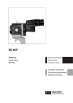
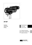
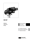
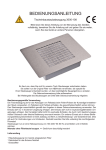
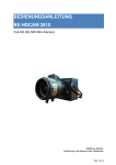
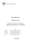
Camera Module CM 900®
Zubehör zu HAAG-STREIT Spaltlampen
Accessoire pour lampes à fente HAAG-STREIT
Accessory to HAAG-STREIT slit lamps
1500.7220044.04020
CM04020.indd 1
Gebrauchsanweisung
Mode d'emploi
Instruction manual
© HAAG-STREIT AG, CH-3098 Koeniz, Switzerland
31.05.10 14:56:42
Vorwort
Avant-propos
Wir danken Ihnen, dass Sie sich für ein HAAG-STREIT Gerät
entschieden haben.
Nous vous remercions d’avoir choisi un produit HAAGSTREIT.
Bei sorgfältiger Einhaltung der Vorschriften in dieser Gebrauchsanweisung können wir Ihnen eine zuverlässige und problemlose
Anwendung unseres Produktes gewährleisten.
Si les instructions dans le présent mode d’emploi sont strictement observées, nous pouvons vous assurer que l’utilisation
de cet instrument ne vous causera aucun problème.
Zweckbestimmung
Das Camera Module CM 900® ist ein Zubehör zu HAAGSTREIT Spaltlampen mit dem digitale Fotografien und Videos
zur Dokumentation des menschlichen Auges hergestellt werden
können. Es wird hauptsächlich in Arztpraxen, Krankenhäusern
und Universitäten bei normalen Umgebungsbedingungen
eingesetzt. Zu den Anwendern gehören Ophthalmologen,
Optometristen und Optiker.
Inhaltsverzeichnis
1
Sicherheit . . . . . . . . . . . . . . . . . . . . . . 4
2
2.1
2.2
2.3
2.4
2.5
Übersicht
Camera Module CMX02
auf BMV 900, BD 900 . . . . . . . . . . . . 8
Camera Module CM 900
auf BP 900 . . . . . . . . . . . . . . . . . . . . 8
Release Module RMX01 . . . . . . . . . . . . 8
Camera Module CMX02
auf BQ 900 . . . . . . . . . . . . . . . . . . . 10
Release Module RMX01 . . . . . . . . . . . 10
3
3.1
3.2
3.3
3.4
3.5
3.6
Installation
Das ���������������
CMX02 montieren . . . . . . . . . . . . 12
Kabel montieren . . . . . . . . . . . . . . . . . 12
Bildschärfe und Position . . . . . . . . . . . 12
. . . . . . . . .
Gewichtsausgleich . . . . . . . . . . . . . . . 14
. . . .
Montage . .
des . . . . . . . . . Aufklebers für die
autom. Links/Rechts Erkennung . . . 14
. . . . . .
Verkabelung
des CMX02 und des RMX01 . . . . . . 14
4
Software / System
������
in Betrieb nehmen . . . . . . . . . . . . . 16
5
Systemkomponenten . . . . . . . . . . . . 18
6
Zubehör . . . . . . . . . . . . . . . . . . . . . . 19
7
Technische Daten . . . . . . . . . . . . . . 20
© HAAG-STREIT AG, CH-3098 Koeniz, Switzerland
CM04020.indd 2
Objectif d'usage
Le Camera Module CM 900® est un accessoire pour lampes à
fente HAAG-STREIT permettant de réaliser des photographies
et vidéos numériques de l'œil humain pour les documenter.
Il est utilisé essentiellement dans les cabinets de médecin,
dans les hôpitaux et dans les universités sous des conditions
normales. Il est utilisé par des ophtalmologues, des optométristes et des opticiens.
Table des matières
1
Sécurité . . . . . . . . . . . . . . . . . . . . . . . . . . . 4
2
2.1
2.2
2.3
2.4
2.5
Nomenclature
Camera Module CMX02
sur BMV 900, BD 900 . . . . . . . . . . . . . . . 8
Camera Module CM 900
sur BP 900 . . . . . . . . . . . . . . . . . . . . . . . 8
Release Module RMX01 . . . . . . . . . . . . . . . 8
Camera Module CMX02
sur BQ 900 . . . . . . . . . . . . . . . . . . . . . . 10
Release Module RMX01 . . . . . . . . . . . . . . 10
3
3.1
3.2
3.3
3.4
3.5
3.6
Installation
Installer le CMX02 . . . . . . . . . . . . . . . . . . 12
Installer les câbles . . . . . . . . . . . . . . . . . . 12
Netteté de l'image et position . . . . . . . . . . 12
Compensation de poids . . . . . . . . . . . . . . . 14
Montage de l’autocollant pour la
�����������������������������������
détection automatique gauche/droite . . . 14
Câblage
. . . .
du CMX02 et du RMX01 . . . . . . . . . . . . 14
4
Logiciel / �������
système
mise en service . . . . . . . . . . . . . . . . . . 16
5
Composants de système . . . . . . . . . . . . 18
6
Accessoires . . . . . . . . . . . . . . . . . . . . . . . 19
7
Caractéristiques techniques . . . . . . . . . 20
1500.7220044.04020
31.05.10 14:56:43
Introduction
We would like to thank you for your decision to purchase this
HAAG-STREIT product.
If the instructions in this manual are carefully followed we are
confident that this product will give you reliable and troublefree usage.
Purpose of use
The Camera Module CM 900® is an accessory to HAAGSTREIT slit lamps and allows digital photography and video for
documentation of the human eye. It is used at room temperature,
usually by Ophthalmologists, Optometrists or Opticians in their
consulting rooms, clinics, hospitals or teaching facilities.
Komponenten / Composantes / Components
Camera Module CMX02
Contents
+ Release Module
1
Safety . . . . . . . . . . . . . . . . . . . . . . . . . 5
2
2.1
2.2
2.3
2.4
2.5
Overview
Camera Module CMX02
on BMV 900, BD 900 . . . . . . . . . . . . 8
Camera Module CM 900
on BP 900 . . . . . . . . . . . . . . . . . . . . . 8
Release Module RMX01 . . . . . . . . . . . . 8
Camera Module CMX02
on BQ 900 . . . . . . . . . . . . . . . . . . . . 10
Release Module RMX01 . . . . . . . . . . . 10
3
3.1
3.2
3.3
3.4
3.5
3.6
Installation
Install������
CMX02 . . . . . . . . . . . . . . . . . . . 13
Install cables . . . . . . . . . . . . . . . . . . . . 13
Image focus and position . . . . . . . . . . 13
Load compensation . . . . . . . . . . . . . . 15
Attaching the sticker for
automatic left/right detection . . . . . . 15
. . . . . Connecting
the CMX02 and RMX01 . . . . . . . . . . 15
4
. . . . . . . . .
Software / system
starting up . . . . . . . . . . . . . . . . . . . 17
5
System components . . . . . . . . . . . . . 18
6
Accessories . . . . . . . . . . . . . . . . . . . . 19
7
Technical specifications . . . . . . . . . 21
HS Footswitch oder RMX01
ou
or
auf Spaltlampe / sur Lampe à fente / on Slit lamp
BMV 900
BD 900
BP 900
BQ 900
CM04020.indd 3
1)
BQ 900
+ Software EyeCap™ / EyeSuite™
= Camera Module CM 900®
1)
1500.7220044.04020
RMX01
BMV seit / dés / since 08.2003
© HAAG-STREIT AG, CH-3098 Koeniz, Switzerland
31.05.10 14:56:43
1
Sicherheit
Umweltbedingungen
• Transport Temperatur
Luftdruck
Relative Feuchte
• Lagerung Temperatur
Luftdruck
Relative Feuchte
• Gebrauch Temperatur
Luftdruck
Relative Feuchte
CM04020.indd 4
1
-40 °C bis
500 hPa bis
10%
bis
-10 °C bis
700 hPa bis
10%
bis
+10 °C bis
800 hPa bis
30%
bis
+70 °C
1060 hPa
95%
+55 °C
1060 hPa
95%
+35 °C
1060 hPa
75%
Sécurité
Conditions de l'environnement
• Transport Température
Pression atmosph.
Humidité relative
• Stockage Température
Pression atmosph.
Humidité relative
• Travail
Température
Pression atmosph.
Humidité relative
-40 °C
500 hPa
10%
-10 °C
700 hPa
10%
+10 °C
800 hPa
30%
à
à
à
à
à
à
à
à
à
+70 °C
1060 hPa
95%
+55 °C
1060 hPa
95%
+35 °C
1060 hPa
75%
Montage
• Instrument vor dem Auspacken einige Stunden in der Verpackung belassen (Kondensation).
• Prüfen, ob die Verbindungsteile des Zubehörs festsitzen
(Schraubverbindungen, Schnellverschluss).
• Installation nur durch geschultes Fachpersonal.
Installation
• Afin d'éviter toute condensation, veillez à laisser l'instrument
dans l'emballage pendant plusieurs heures.
• Rassurez-vous que les raccords pour les accessoires sont
serrés (assemblages par vis, fermeture rapide).
• Toute installation doit être effectuée par un spécialiste avec
une formation adéquate.
Bedienung, Umgebung
• Bedienung nur durch qualifiziertes und geschultes Personal,
dessen Ausbildung ist Aufgabe des Betreibers.
• Für die Diagnose eines Patienten ist das Bild im Okular
massgebend.
• Nur HAAG-STREIT Zubehör verwenden.
• Nach jedem Betrieb Instrument ausschalten. Bei Verwendung
der Staubschutzhülle: Gefahr durch Überhitzung.
• Instrument nicht in explosionsgefährdeten Bereichen benutzen, keine flüchtigen Lösungsmittel (Alkohol, Benzin usw.) und
brennbare Narkosemittel in der Nähe verwenden.
• Feuchtigkeit vermeiden.
• Vor jeder Untersuchung prüfen, ob das RMX01 korrekt arbeitet.
• Voreinstellungen nicht über den Bildschirm vornehmen, sondern durch das Okular. So werden Kollisionen der Spaltlampe
mit dem Patientenkopf vermieden.
Opération et environnement
• Seul un personnel qualifié et formé a le droit d'utiliser cet instrument, la formation des opérateurs incombe au propriétaire.
• Pour le diagnostic d’un patient, l’image dans l’oculaire est
déterminante.
• Utilisez seulement les accessoires HAAG-STREIT.
• Eteindre après chaque utilisation. Avec l'utilisation de la housse
en plastique: risque de surchauffer.
• N’utilisez jamais l’instrument dans des zones où il y a des
gaz explosifs, des vapeurs combustibles (alcool, benzol) ou
des agents anesthésiques inflammables.
• Evitez toute source d'humidité.
• Avant chaque examen il faut s'assurer que le RMX01 fonctionne correctement.
• Les préréglages ne doivent pas être effectués par le biais
de l’écran mais à l’aide de l’oculaire. Cela permet d’éviter les
collisions entre la lampe à fente et la tête du patient.
Elektrisches
• Nur typengeprüfte 3-polige Netzkabel verwenden.
Für USA und Kanada Netzkabelset, nach UL-Liste, Typ SJE,
SJT oder SJO, 3-polig, nicht kleiner als 18 AWG.
• Stecker, Kabel und Schutzleiteranschluss der Steckdose
müssen einwandfrei funktionieren.
• Das Release Module RMX01 wird mit starken Magneten befestigt. Magnetempfindliche Speichermedien fern halten.
• Nur PC’s verwenden, welche die Norm EN/IEC60601-1 erfüllen, oder über einen Trenntransformator betreiben. Die EMV
Fachgrundnorm (Elektromagnetische Verträglichkeit )nach EN
61000 ist einzuhalten.
• Zusatzgeräte am PC (z.B. Drucker, Monitor, Scanner) müssen über einen Trenntransformator betrieben werden. Auf diese
Massnahme kann verzichtet werden, wenn mit einer drahtlosen Verbindung (z.B. Bluetooth) gearbeitet wird.
• Ethernet darf nur über eine galvanische Trennung nach EN/
IEC60601-1 verwendet werden.
• Nur mitgelieferte USB-Kabel als Verbindung zum PC verwenden.
Installation électrique
• N'utilisez que des câbles d'alimentation secteur à trois conducteurs homologués. Pour USA et Canada: Câble d'alimentation
électrique, selon UL, type SJE, SJT ou SJO, tripolaire, plus
grand que 18 AWG.
• Toutes les fiches, les câbles et le conducteur de protection
de la prise doivent être en état parfait.
• Le Release Module RM01 est fixé à l’aide d’aimants puissants. Il
convient de tenir à l’écart les supports de mémoire sensibles.
• Utiliser uniquement des PC qui satisfont à la norme EN/
IEC60601-1, ou un transformateur de séparation. La norme
générique CEM (compatibilité électromagnétique) selon EN
61000 doit être respectée.
• Les appareils périphériques du PC (p.ex. imprimante, moniteur, scanner) doivent être utilisés avec un transformateur
de séparation. Cette mesure n’est pas nécessaire si on utilise
une connexion sans fil (p.ex. Bluetooth).
• Ethernet ne doit être utilisé que par le biais d’une séparation
galvanique selon EN/IEC60601-1.
• Utiliser uniquement les câbles USB fourni pour la connexion avec le PC.
© HAAG-STREIT AG, CH-3098 Koeniz, Switzerland
1500.7220044.04020
31.05.10 14:56:43
1
Safety
Ambient conditions
• Transportation Temperature
Air pressure
Relative humidity
• Storage
Temperature
Air pressure
Relative humidity
• Working
Temperature
Air pressure
Relative humidity
-40 °C to
500 hPa to
10%
to
-10 °C to
700 hPa to
10%
to
+10 °C to
800 hPa to
30%
to
+70 °C
1060 hPa
95%
+55 °C
1060 hPa
95%
+35 °C
1060 hPa
75%
Installation
• To avoid condensation, allow the instrument to adjust to room
temperature for several hours before unpacking.
• Check that all components are fitted correctly (screwed
connections, quick fit).
• All installations must be carried out by suitably trained personnel.
Operation and surrounding
• Only qualified and trained personnel should operate the
equipment, the training is at the owner’s responsibility.
• The image obtained via the eyepiece takes precedence when
examining a patient.
• Use only HAAG-STREIT accessories.
• Shut down after every use. In case the dust cover is used:
risk of overheating.
• Never operate the instrument in the same room with combustible gases, volatile solvents (alcohol, benzol) or flammable
anesthetic agents.
• Avoid humidity.
• Check that the RMX01 is operating correctly before each
examination.
• Make preliminary adjustments via the eyepiece rather than
on-screen. This helps prevent the slit lamp from knocking
against the patient’s head.
Electrical
• Only hospital grade 3-conductor electrical power supply cables
must be used. For USA and Canada: Detachable Power Supply
Cord Set, UL listed, type SJE, SJT or SJO, 3-conductor, not
smaller than 18 AWG.
• Plug, cable and ground lead connection of the socket have
to be in perfect condition.
• The RM01 Release Module is secured with powerful magnets.
Keep away from sensitive data-storage items.
• Use only PCs that conform to EN/IEC60601-1 standards, or
operate them via a transformer that isolates them from the power supply. Generic EMC (electromagnetic compatibility) standards must be observed in accordance with EN 61000.
• PC peripherals (printers, monitors, scanners, etc.) must be
operated via a transformer that isolates them from the power
supply. These stipulations do not apply if a wireless connection (e.g. Bluetooth) is used.
• Ethernet connections must be configured with galvanic isolation in accordance with EN/IEC60601-1.
• Connect to the PC only with the USB-cables supplied.
1500.7220044.04020
CM04020.indd 5
Umwelt
• Elektro- und Elektronikgeräte müssen getrennt
vom Hausabfall entsorgt werden! Dieses Gerät wurde nach dem 13.08.2005 in den Handel gebracht.
• Entsorgung über die lokale Sammelstelle oder
über Ihren HAAG-STREIT Vertreter.
• Damit ist gewährleistet, dass keine schädlichen
Stoffe in die Umwelt gelangen und wertvolle Rohstoffe wieder Verwendung finden.
Environnement
• Les appareils électriques et électroniques ne
doivent pas être jetés avec les déchets de ménage! Cet appareil a été introduit sur le marché
après le 13.08.2005.
• L‘enlèvement des déchets s‘effectue au point
de ramassage local ou chez votre distributeur
HAAG-STREIT.
• Ainsi il est garanti qu‘aucune matière nuisible
n‘arrive dans l‘environnement mais que les matières premières précieuses soient reutilisées.
Environment
• Electric and electronic equipment must be separated from house waste! This equipment has
been introduced into the market after the 13th
of August 2005.
• Disposal via your local collecting point or your
HAAG-STREIT distributor.
• Thus it is ensured, that no harmful materials
get into the environment and that valuable raw
materials can be used again.
© HAAG-STREIT AG, CH-3098 Koeniz, Switzerland
31.05.10 14:56:43
Reinigung
• Gehäuse nur mit leicht angefeuchtetem Tuch reinigen.
• Keine Flüssigkeiten, keinen Alkohol, keine ätzenden Mittel.
• Nur die Aussenflächen der Optikteile säubern.
Garantie / Produktehaftpflicht
• Das Produkt ist entsprechend dem Kapitel 'Sicherheit' zu
behandeln. Unsachgemässe Behandlung kann zu Schäden
am Produkt führen. Dadurch erlöschen sämtliche Garantieansprüche.
• Wird ein durch unsachgemässe Behandlung beschädigtes
Produkt weiterhin eingesetzt, kann dies zu Personenschäden
führen. Der Hersteller haftet in diesem Fall nicht.
• Instandsetzungen und Änderungen am Produkt dürfen nur
von HAAG-STREIT Servicetechnikern oder von autorisierten
Personen durchgeführt werden.
CM04020.indd 6
Nettoyage
• Nettoyez le boîtier seulement avec un linge légèrement
humide.
• N’utilisez aucun liquide, pas d'alcohol, ni de produits abrasifs.
• Nettoyez uniquement l’extérieur des pièces de l’optique.
Garantie / responsabilité de produit
• Cet instrument doit être manipulé conformément aux consignes
énoncées au chapitre 'Sécurité'. Une utilisation non conforme
à ces consignes est susceptible d’entraîner des dommages sur
l’instrument. Ainsi le client perd tout bénéfice de la garantie.
• Si un produit endommagé par une utilisation non conforme
continue à être utilisé, il est susceptible de causer des dommages aux personnes. Dans ce cas, le fabricant décline toute
responsabilité.
• Seuls les techniciens HAAG-STREIT ou des personnes autorisées ont le droit de réparer ou de modifier l'instrument.
Gesetzliche Vorschriften
• Das Camera Module CM 900® wurde unter Berücksichtigung der
Normen IEC / EN 60 601-1 und ISO 10939 konstruiert. Unter der
Beachtung schweizerischer und internationaler Auflagen erfolgen
Fertigung, Prüfung, Aufstellung, Wartung und Reparatur.
• Beim Kombinieren verschiedener medizinisch und/oder
nichtmedizinisch elektrischer Geräte ist die Norm IEC / EN
60 601-1 zu berücksichtigen.
• Das Camera Module CM 900® darf nur in einem Umfeld
betrieben werden, in welchem die Normwerte nach EN/IEC
60601-1 eingehalten werden, sonst können Funktionsstörungen auftreten.
• Durch die CE-Kennzeichnung wird die Übereinstimmung des
Camera Module CM 900® mit den Richtlinien 93/42/EWG und
89/336/EWG und dem Konformitätsmodul A bestätigt.
• Eine Kopie der Konformitätserklärung und der EMV Hinweise
(Elektromagnetische Verträglichkeit) zum vorliegenden Instrument kann jederzeit bei HAAG-STREIT angefordert werden.
• Die gesetzlichen Unfallverhütungsvorschriften sind zu
beachten.
• Klassierung
Norm IEC / EN 60 601-1 Spaltlampenzubehör nach
Schutzklasse I
Anwendungsteil Typ B
Betriebsart: Dauerbetrieb
CE-Richtlinie 93/42 EWG Klasse I
FDA
Klasse I
Dispositions légales
• Le Camera Module CM 900® a été conçu conformément aux
normes IEC / EN 60 601-1 et ISO 10939. La fabrication,
le test, le montage, l’entretien et la réparation doivent être
effectués en respectant les dispositions légales suisses et
internationales.
• Lors de combinaison de différents instruments médicaux
et/ou non-médicaux électriques, la norme IEC / EN 60 601-1
doit être observée.
• Le Camera Module CM 900® doit être utilisé uniquement dans
un environnement dans lequel les valeurs selon la norme EN/
IEC 60601-1 sont respectées, sinon des dysfonctionnements
peuvent apparaître.
• L’insigne CE indique que le Camera Module CM 900® est
conforme aux prescriptions 93/42/CEE et 89/336/CEE et au
module de conformité A.
• Une copie de la déclaration de conformité et des remarques concernant la CEM (Compatibilité électromagnétique) de cet instrument
peut être demandée à tout instant à l'entreprise HAAG-STREIT.
• Les dispositions légales de prévention des accidents doivent
être observées.
• Classification
Norme IEC / EN 60 601-1Accessoire pour lampe à fente
classe de protection I
Partie d’application type B
Mode d’exploitation: a longue durée
Directive CE 93/42 CEE Classe I
FDA
Classe I
Piktogramme
a Gebrauchsanweisung mit Aufmerksamkeit lesen!
b Netzstecker ziehen!
c Magnetempfindliche Speichermedien fern halten!
Nur für RMX01:
d Steckbuchse am RMX01 für Gerätenetzteil
e Steckbuchse am RMX01 für CMX02
f Steckbuchse am RMX01 für Computer
g Hersteller
h HS Bestellnummer
i Produkteklassifikation Typ B
k Seriennummer
l Herstellungsdatum
Pictogrammes
a Lire avec attention le mode d'emploi!
b Retirez la prise électrique!
c Tenir à l’écart les supports de mémoire sensibles aux aimants
Seulement pour RMX01:
d Fiche femelle du RMX01 pour alimentation secteur
e Fiche femelle du RMX01 pour CMX02
f Fiche femelle du RMX01 pour ordinateur
g Fabricant
h HS numéro de commande
i Classification de produit type B
k Numéro de série
l Date de fabrication
© HAAG-STREIT AG, CH-3098 Koeniz, Switzerland
1500.7220044.04020
31.05.10 14:56:43
Cleaning
• Clean the housing only with a slightly water dampened
cloth.
• No liquids, no alcohol or corrosive agents.
• Clean only the exterior surfaces of the optical parts.
Warranty / product liability
• The instrument should be operated in accordance with the
chapter 'Safety'. Incorrect operation can damage the instrument.
Thus no warranty claims can be accepted.
• Continued use of an instrument that has been damaged by
incorrect operation can lead to personal injury. The manufacturer
cannot accept liability in this case.
• Repairs and alterations on this equipment should only be
carried out by HAAG-STREIT service technicians or by authorized persons.
Statutory requirements
• The Camera Module CM 900® has been designed to conform
with the IEC / EN 60 601-1 and ISO 10939 standards. Manufacturing procedures, testing, commissioning, maintenance
and repair are conducted under the observance of Swiss and
international regulations.
• When combining different medical and/or nonmedical electrical
equipment standard IEC / EN 60 601-1 applies.
• The Camera Module CM 900® must only be operated in situations where EN/IEC 60601-1 standards can be maintained,
otherwise malfunctions may occur.
• The 'CE' marking confirms compliance of the Camera Module
CM 900® with the directives 93/42/EEC and 89/336/EEC and
the conformity module A.
• A copy of the declaration of conformity and information concerning EMC (Electromagnetic compatibility) of the present
instru-ment can be requested at any time at HAAG-STREIT
company.
• All statutory accident prevention regulations are to be observed.
• Classification
IEC / EN Standard 60 601-1 Slit lamp accessory
safety class I
Application part Type B
Operation mode: continuous
operation
CE-Regulation 93/42 EEC Class I
FDA
Class I
Pictograms
a Read very carefully the instruction manual!
b Disconnect the electrical supply plug!
c Keep magnetic data-storage items away
RMX01 only:
d Tip jack on RMX01 for power supply
e Tip jack on RMX01 for CMX02
f Tip jack on RMX01 for computer
g Manufacturer
h HS-Part Number
i Type B equipment
k Serial number
l Date of manufacture
b
c
Input
5V DC±1%/1.2A
d
e
g h
Product: Release Module
Type:
RM01
HAAG-STREIT AG
Gartenstadtstrasse 10
3098 Koeniz, Switzerland
1500.7220044.04020
CM04020.indd 7
a
f
i
Swiss made
Caution: Federal law restricts this
device to sale by or on the order
of a Physician or Practitioner
1234 1234567 12345
k
l
HAAG-STREIT AG
2006
© HAAG-STREIT AG, CH-3098 Koeniz, Switzerland
31.05.10 14:56:43
BMV 900
BD 900
BP 900
2
Übersicht
2
Nomenclature
2
Overview
2.1
Camera Module CMX02
auf BMV 900® oder BD 900®
2.1
Camera Module CMX02
sur BMV 900® ou BD 900®
2.1
Camera Module CMX02
on BMV 900® or BD 900®
3
4
5
6
7
8
9
10
11
Feststellschraube
Feststellring
Camera Module CMX02 mit
Logo (Kamera richtige Position:
weg vom Mikroskop)
Kabel Umfeldbeleuchtung
Kabelhalter
Kamerakabel
Anschlusskabel Computer (USB)
Release Module RMX01
Fussschalter
3
4
5
6
7
8
9
10
11
Vis de fixation
Bague de fixation
Camera Module CMX02 avec
logo (position correcte de la
caméra: loin du microscope)
Câble éclairage d'ambiance
Porte-câbles
Câble de caméra
Câble raccordement ordinateur (USB)
Release Module RMX01
Commutateur de pied
3
4
5
6
7
8
9
10
11
Fixation screw
Fixation ring
Camera Module CMX02 with
logo (correct position of camera:
opposite of microscope)
Background illumination cable
Cable holder
Camera cable
Connection cable computer (USB)
Release Module RMX01
Footswitch
HAAG-STREIT empfiehlt die Verwendung folgender Komponenten
1 Integrierte Umfeldbeleuchtung
(Lichtleiter)
2 Okular
mit Doppelfadenkreuz
14 Kaltlichtquelle
HAAG-STREIT recommande l'utilisation
des composants suivantes
1 Eclairage d'ambiance intégré
(conducteur en fibre optique)
2 Oculaire
avec double réticule croisée
14 Source de lumière froide
HAAG-STREIT recommends the use of
following components
1 Integrated background illumination
(optical light lead)
2 Eyepiece
with double crosshair reticule
14 Cold light source
2.2
Camera Module CMX02
auf BP 900®
2.2
2.2
13
15
16
22
23
24
25
27
28
Feststellschraube
Kamerakabel (USB)
Anschlusskabel Computer (USB)
Stecker Kamerakopf des
Camera Module CMX02
Leuchtdiode (LED) Statusanzeige
rot =Initialisierung / Fehler
grün=Betriebsbereit
Hebel Strahlenteiler (70 / 30)
Feststellring
Kabelhalter
Release Module RMX01
13
15
16
22
23
24
25
27
28
Vis de fixation
Câble de caméra (USB)
Câble raccordement ordinateur (USB)
Prise tête de caméra du
Camera Module CMX02
Diode (LED) indicateur
rouge = initialisation / erreur
vert = prêt à démarrer
Levier diviseur optique (70 / 30)
Bague de fixation
Serre-câble
Release Module RMX01
13
15
16
22
23
24
25
27
28
Camera Module CMX02
on BP 900®
Fixation screw
Camera cable (USB)
Connection cable computer (USB)
Plug on camera head of
Camera Module CMX02
Light diode (LED) indicator
red = initialisation / error
green = ready for use
Control lever beam splitter (70 / 30)
Fixation ring
Cable holder
Release Module RMX01
HAAG-STREIT empfiehlt die Verwendung folgender Komponenten
12 Umfeldbeleuchtung
Schwenkspiegel
26 Okular
mit Doppelfadenkreuz
14 Kaltlichtquelle
HAAG-STREIT recommande l'utilisation
des composants suivantes
12 Eclairage d'ambiance
miroir pivotant
26 Oculaire
avec double réticule croisée
14 Source de lumière froide
HAAG-STREIT recommends the use of
following components
12 Background illumination
pivoting mirror
26 Eyepiece
with double crosshair reticule
14 Cold light source
2.3
Release Module RMX01
2.3
Release Module RMX01
2.3
Release Module RMX01
17
18
19
20
21
Rechte Taste= heller
Linke Taste = dunkler
Auslösetaste
Drei Kleber auf Unterseite
Schutzfolie entfernen und RMX01
links oder rechts neben
Lenkhebel auf Basis befestigen
17
18
19
20
21
Touche gauche= plus lumineux
Touche droite = moins lumineux
Déclencheur
Trois autocollants en dessous
Enlever la feuille de protection
et fixer RMX01 à gauche ou à
droite du palonnier sur la base
17
18
19
20
21
Right key = more exposure
Left key = less exposure
Trigger
Three stickers on lower surface
Remove protection foil and fix
RMX01 on the base at right or
left side of control lever
© HAAG-STREIT AG, CH-3098 Koeniz, Switzerland
CM04020.indd 8
Camera Module CMX02
sur BP 900®
1500.7220044.04020
31.05.10 14:56:43
17
18
19
20
21
1
2
3
4
5
6
7
8
9
22
23
24
25
10
11
12
13
14
15
26
27
16
28
1500.7220044.04020
CM04020.indd 9
© HAAG-STREIT AG, CH-3098 Koeniz, Switzerland
31.05.10 14:56:43
BQ 900
2.4
Camera Module CMX02
auf BQ 900
2.4
Camera Module CMX02
sur BQ 900
2.4
30
31
37
39
40
41
Kabelhalter
Kamerakabel
(CMX02 - RMX01)
Leuchtdiode (LED) Statusanzeige
rot =Initialisierung / Fehler
grün=Betriebsbereit
Hebel Strahlenteiler
Feststellring
Feststellschraube am
Videoadapter
30
31
37
39
40
41
Porte-câbles
Câble de caméra
(CMX02 - RMX01)
Diode (LED) indicateur
rouge = initialisation / erreur
vert = prêt à démarrer
Bouton diviseur optique
Bague de fixation
Vis arrêt au
Adaptateur vidéo
30
31
37
39
40
41
2.5
Release Module RMX01
2.5
Release Module RMX01
2.5
32
33
34
35
43
44
45
46
47
48
Gaine tressée
Serre-câble
Câble de l'ordinateur
(RMX01 - ordinateur)
Câble de l'alimentation secteur
(RMX01 - alimentation secteur)
Autocollant pour la détection
gauche/droite
Touche = plus lumineux
Touche = moins lumineux
Déclencheur
Touche = plus lumineux
Touche = moins lumineux
32
33
34
35
43
44
45
46
47
48
32
33
34
35
43
44
45
46
47
48
Flechtschlauch
Kabelbinder
Computerkabel
(RMX01 - Computer)
Gerätenetzteilkabel
(RMX01 - Gerätenetzteil)
Aufkleber
Links/Rechts Erkennung
Taste = heller
Taste = dunkler
Auslösetaste
Taste = heller
Taste = dunkler
Camera Module CMX02
on BQ 900
Cable holder
Camera cable
(CMX02 - RMX01)
Light diode (LED) indicator
red = initialisation / error
green = ready for use
Control knob beam splitter
Fixation ring
Fixing screw at
Video adapter
Release Module RMX01
Conduit tube
Cable tie
Computer cable
(RMX01 - computer)
Power supply cable
(RMX01 - power supply)
Sticker
left/right recognition
Key = more exposure
Key = less exposure
Trigger
Key = more exposure
Key = less exposure
36 Gerätenetzteil mit
50 Netzstecker (landesabhängig)
36 Alimentation secteur avec
50 Prise (dépendant du pays)
36 Power supply with
50 Plug (country depending)
HAAG-STREIT empfiehlt die Verwendung folgender Komponenten
HAAG-STREIT recommande l'utilisation
des composants suivantes
HAAG-STREIT recommends the use of
following components
29
42
49
29
42
49
29
42
49
10
Umfeldbeleuchtung
Schwenkspiegel
Okular
mit Doppelfadenkreuz
Kaltlichtquelle
© HAAG-STREIT AG, CH-3098 Koeniz, Switzerland
CM04020.indd 10
Eclairage d'ambiance
miroir pivotant
Oculaire
avec double réticule croisée
Source de lumière froide
Background illumination
pivoting mirror
Eyepiece
with double crosshair reticule
Cold light source
1500.7220044.04020
31.05.10 14:56:44
37
38
Camera Module CMX02
39
40
41
29
42
Release Module
43
30
31
44
45
46
47
48
32
49
11
33
34
35
50
36
1500.7220044.04020
CM04020.indd 11
© HAAG-STREIT AG, CH-3098 Koeniz, Switzerland
31.05.10 14:56:44
BMV 900
BD 900
BP 900
BQ 900
12
CM04020.indd 12
3
Installation
3
Installation
3.1
Das CMX02 montieren
3.1
Installer le CMX02
• Atemschutzschild demontieren.
• Abdeckkappen an Kamera und Adapter entfernen.
• Die 3 Feststellschrauben (51) an Adapter lösen. Adapter (52)
auf Kamera schrauben.
• Kamera drehen bis Position richtig und dann mit den 3 Feststellschrauben (51) festsetzen. Bildaufrichtung mit PC.
• Eine Distanzschraube (54) muss eingebaut werden, damit
der Atemschutzschild korrekt montiert werden kann.
• Démonter la plaque de protéction hygiénique.
• Enlever les capuchons de la caméra et de l'adaptateur.
• Deserrer les 3 vis de fixation (51) de l'adaptateur. Visser
l'adaptateur (52) sur la caméra.
• Tourner la caméra en position correcte et la fixer ensuite à
l'aide des 3 vis de fixation (51). Redresser l'image au PC.
• Il faut installer une vice de distance (54), afin que la plaque
de protéction hygiénique puisse être montée proprement.
• Abdeckkappen entfernen.
• Markierungspunkte (58) auf der Oberseite der zu verbindenden
Teile zueinander ausrichten.
• Verbinden und den Feststellring in der angegebenen Pfeilrichtung durch Drehen fest anziehen.
• Videoadapter positionieren, Feststellring (59) anziehen.
• Feststellschraube (60) oder (61) an Videoadapter lösen.
Kamera auf Adapter schrauben, drehen bis Position richtig,
Feststellschraube fixieren.
• Enlever les capuchons.
• Mettre les deux pièces l'un en face de l'autre en faisant correspondre les deux repères (58).
• Raccorder et serrer solidement la bague de fixation dans le
sens de la flèche en la tournant.
• Positionner l'adaptateur vidéo, serrer la bague de fixation (59).
• Deserrer la vis de fixation de l'adaptateur (60) ou (61). Visser
la caméra sur l'adapateur et la tourner en position correcte.
3.2
3.2
Kabel montieren
Installer les câbles
• Das Kamerakabel (56) am Kamerakopf (55) einstecken,
eventuell durch den Tisch führen und an den Computer anschliessen. Möglichkeiten: siehe Kapitel 2.
• An der Spaltlampe wird das Kabel am Mikroskoparm mit zwei
Kabelhaltern (57) befestigt.
• Introduire le câble de la caméra (56) sur la tête de la caméra
(55), le passer éventuellement à travers la table et le raccorder
à l’ordinateur. Pour les possibilitées: voir chapitre 2.
• Le câble est fixé à la lampe à fente au bras de microscope
à l'aide de deux porte-câbles (57).
3.3
3.3
Bildschärfe und Position
Netteté de l'image et position
Position der Kamera beachten! Kamera muss so montiert werden, dass das Bild korrekt auf dem Bildschirm erscheint. Kamera
so drehen: das Kamerakabel zeigt Richtung Mikroskoparm,
das HAAG-STREIT Logo (53) ist also gut sichtbar.
Observer la position de la caméra! La caméra doit être montée
de manière à ce qu'il en résulte une image correcte sur l'écran.
Tourner la caméra ainsi: le câble montre en direction du microscope, donc le logo HAAG-STREIT (53) est bien visible.
Falls das Bild nicht korrekt auf dem Bildschirm positioniert
ist: Feststellschrauben (51) oder (60) oder (61) leicht lösen,
Kamera um Längsachse drehen, bis Position stimmt; Kamera
wieder fixieren. Über die Software kann das Bild horizontal und
vertikal gespiegelt werden.
Au cas où l'image n'est pas positionnée correctement sur
l'écran: deserrer un peu les vis de fixation (51) ou (60) ou (61),
tourner la caméra autour de son axe, jusqu'à ce que la position
soit correcte; fixer la caméra de nouveau. L 'image peut être
inversée horizontalement ou verticalement par le logiciel.
Bildschärfe auf dem Bildschirm muss nicht eingestellt werden,
Anschluss wurde so konzipiert, dass Bildschärfe automatisch
optimal ist!
La netteté de l’image vidéo sur l’écran ne doit pas être ajustée,
car l'instrument à été conçu de manière à ce que la netteté
soit optimale automatiquement!
Damit auf dem Bildschirm die gleiche Objektebene scharf
abgebildet wird wie im Okular, müssen die Okulare mit dem
Justierstab genau eingestellt werden.
Oder, HAAG-STREIT Empfehlung: Scharf einstellen mit dem
Doppelfadenkreuz Okular.
Afin de reproduire nettement à l’écran le même plan d’objet que
dans l’oculaire, il convient de régler exactement les oculaires
à l’aide de la tige d’ajustage.
Ou bien, la recommandation HAAG-STREIT: Régler nettement
à l'aide de l'oculaire avec double réticule croisée.
Durch die Koppelung der Akkommodation mit dem konvergenten Sehen, ist oft eine Korrektur der normalen Refraktion um
-1 bis -2 dpt am Okular nötig.
Du fait de l’accouplement de l’accommodation avec la vue
convergente, la réfraction normale doit souvent être corrigée
sur l’oculaire de -1 à -2 dpt.
© HAAG-STREIT AG, CH-3098 Koeniz, Switzerland
1500.7220044.04020
31.05.10 14:56:44
3
Installation
3.1
Install CMX02
• Remove breath shield.
• Remove the cover on camera and adapter.
• Unscrew the 3 fixing screw (51) on the adapter. Tighten adapter (52) on camera.
• Rotate the camera into correct position and then affix it with
3 set screws (51). Setting image upright at PC.
• A distance screw (54) must be built in, thus the breath shield
can be fixed correctly.
• Remove the cover.
• Align the positioning points (58) on the upper side of the
parts to be joined.
• Push together and tighten firmly the joint in direction of the
arrow by turning it.
• Position video adapter, tighten fixation ring (59).
• Loosen fixation screw (60) or (61) on video adapter. Tighten
camera on adapter, rotate it into correct position, fix it with fixation screw.
3.2
52
53
54
55
56
57
BMV 900
BD 900
Install cables
• Secure the camera cable (56) to the camera head (55), lead
it eventually through the table and connect it to the computer.
Possiblities: see chapter 2.
• On the slit lamp the cable is fixed on the microscope arm
with two cable holder (57).
3.3
51
58
BQ 900
59
Image focus and position
60
Note the position of the camera! The camera must be mounted
in the way, that the picture is correctly displayed on the screen.
Rotate the camera in this way: the camera cable shows in
direction of the microscope, so the HAAG-STREIT logo (53)
is well visible.
13
In the case of misaligned images on the screen: loosen fixation
screws (51) or (60) or (61), rotate the camera until the correct
position image is displayed; fix camera again. The image can
be inverted horizontally or vertically by the software.
Image focus on the monitor needs not to be adjusted, the interface has been designed so that optimal image focus is set
automatically!
To achieve the same focus through both eye-pieces and monitor, the eye-pieces must be exactly adjusted with the focus
test rod.
Or, the HAAG-STREIT recommendation: Correct focussing
with eyepiece with double crosshair reticule.
61
BP 900
When coupling the accommodation facility with convergent
viewing, the normal refraction often has to be corrected by -1
to -2 dpt on the eye-piece.
1500.7220044.04020
CM04020.indd 13
© HAAG-STREIT AG, CH-3098 Koeniz, Switzerland
31.05.10 14:56:45
3.4
BQ 900
14
CM04020.indd 14
Gewichtsausgleich �������������������
(US Pat. 5.016.854)
3.4
Compensation de poids (Pat. US 5.016.854)
Das Gewicht zusätzlicher an das Mikroskop angebauter Zubehörteile kann durch Entlastungsfedern ausgeglichen werden. Die Höhenverstellung der Spaltlampe bleibt dadurch
leichtgängig.
Le poids des pièces accessoires montées sur le microscope
peut être compensé par des ressorts de décharge. Le réglage
en hauteur de la lampe à fente reste ainsi souple dans tous
les cas de surcharge.
Einstellen des Gewichtsausgleichs
• Lenkhebel in unterste Position drehen und wieder um
1/4 Drehung leicht lösen.
• Mikroskop und Beleuchtung zur Seite schwenken.
• Alle drei Federn einschalten:
Réglage du compensateur de poids
• Tourner le levier de manoeuvre dans sa position la plus basse et le desserrer par 1/4 de tour.
• Déplacer latéralement le microscope et le dispositif d' éclairage.
• Embrayer les trois ressorts:
Einschalten
Im Gegenuhrzeigersinn drehen bis die Schrauben (61) vollständig gelöst sind.
Embrayage
Desserrer les vis (61) complètement en les tournant dans le
sens contraire des aiguilles d'une montre.
Ausschalten
Im Uhrzeigersinn drehen bis zum Widerstand.
• Kontrollieren, ob der mit einer Hand nach oben gedrückte
Mikroskoparm nach dem Loslassen nach unten zurückfedert.
Dies wird nur dann geschehen, wenn die Belastung bereits
maximal ist.
• In der Regel müssen so viele Entlastungsfedern wieder ausgeschaltet werden, bis das Zurückfedern nach unten erfolgt.
• Der Gewichtsausgleich ist richtig eingestellt, wenn Beleuchtung und Mikroskop mit den dauernd montierten Zubehörteilen ein leichtes Übergewicht gegenüber den Entlastungsfedern aufweisen.
Débrayage
Tourner dans le sens des aiguilles d'une montre jusqu'à
l'arrêt.
• Soulever le bras du microscope d'une main. Le lâcher et contrôler s'il descend dans sa position de départ ce qui n'arrivera
qu'en cas de charge maximum.
• Débrayer autant de ressorts qui sont nécessaires pour faire
redescendre le système.
• La charge est correctement compensée lorsque le poids
du dispositif d'éclairage et du microscope avec les éléments
montés en permanence excède légèrement la force des ressorts de décharge.
3.5������������������������������
Montage des Aufklebers für die
automatische Links/Rechts Erkennung
3.5 Montage de l’autocollant pour la détection
�������������������������
automatique gauche/droite
• Schienendeckel (66) entfernen und Spaltlampe wegstellen.
Tischoberfläche reinigen.
• Entfernen Sie die Schutzfolie (62) auf der Kleber-Rückseite.
Beginnen Sie vorsichtig in der Ecke gegenüber der schwarzen Fläche.
• Den Aufkleber an die rechte Rollschiene (64) und die Tischkante (65) anschlagen. Weiss-schwarze Fläche festpressen,
Luftblasen ausstreichen.
• Den Rest des Aufklebers (63), 'Positionierungswerkzeug / Positioning tool', entlang der Perforierung vorsichtig entfernen.
• Spaltlampe und Schienendeckel wieder montieren.
• Retirer le cache-rail (66) et déplacer la lampe à fente. Nettoyer la surface de la table.
• Retirer la membrane de protection (62) sur la face arrière
de l’autocollant. Commencer prudemment au coin en face de
la surface noire.
• Positionner l’autocollant sur le rail de roulement (64) et le
bord de la table (65). Presser la surface noire et blanche, éliminer les bulles d’air.
• Enlever soigneusement la partie restante de l’autocollant
(63), 'Outil de positionnement / Positioning tool' le long de la
perforation.
• Remonter la lampe à fente et le cache-rail.
3.6
3.6
Verkabelung des CMX02 und des RMX01
Câblage du CMX02 et du RMX01
ACHTUNG
Stellen Sie sicher, dass alle Netzstecker ausgezogen sind.
ATTENTION
Assurez-vous que toutes les fiches sont débranchées.
• Computerkabel (70) und Gerätenetzteilkabel (68) in den
Flechtschlauch (67) einfädeln.
• Faire glisser le câble de l’ordinateur (70) et le câble de
l'alimentation secteur (68) dans la gaine tressée (67).
• Den Winkelstecker (69) ...
• Faire passer la fiche coudée (69) ...
© HAAG-STREIT AG, CH-3098 Koeniz, Switzerland
1500.7220044.04020
31.05.10 14:56:45
3.4
Load compensation (US Pat. 5.016.854)
The weight of components or accessories added to the microscope can be compensated by relieving springs so that height
adjustment of the slit lamp remains smooth, no matter what
accessories remain permanently mounted.
Compensating the weight of added components
• Turn the control lever down to its lowest stop, then loosen
it by 1/4 turn.
• Swing the microscope and illumination unit to one side.
• Engage all three springs:
61
Kleber Links/Rechts Erkennung
Autocollant Détection gauche/droite
Left/right detection sticker
HS-Part Number 1008072
Engaging
Turn the screws (61) counter-clockwise until they are in the
uppermost position.
Disengaging
Tighten the screws by turning them clockwise.
• Lift the microscope arm with one hand. Release it and check
whether it returns to the original position. This will not happen
unless the maximum load has been added.
• As a rule, it will be necessary to disengage as many relieving
springs as required for ensuring that the arm and spring housing
settle down in their original position.
• The load is adequately counter-balanced when the weight of
illumination unit and microscope with all permanently mounted
components exceeds the compensating force of the springs
by a small amount.
3.5
63
64
65
Attaching the sticker for
automatic left/right detection
• Detach the rail cover (66) and move the slit lamp out of the
way. Clean the surface of the table.
• Remove the protective foil (62) of the sticker. Start with the
corner opposite of the black surface.
• Position the sticker to the right-hand roller rail (64) and the
edge of the table (65). Press down the black and white surface, eliminate any air bubbles.
• Carefully remove the rest of the 'Positionierungswerkzeug
/ Positioning tool' sticker (63) by tearing off along the perforation.
• Refit the slit lamp and rail cover.
3.6
62
15
66
Connecting the CMX02 and RMX01
IMPORTANT
ensure that all mains plugs are
disconnected.
• Thread the computer cable (70) and power supply cable (68)
into the conduit tube (67).
• Insert the angled plug (69) ...
1500.7220044.04020
CM04020.indd 15
67
68
69
70
© HAAG-STREIT AG, CH-3098 Koeniz, Switzerland
31.05.10 14:56:45
... des Gerätenetzteilkabels durch die Öffnung (74) auf der Rückseite des Release Module RMX01 führen und in die Buchse
(77) auf der gegenüber liegenden Seite stecken.
... du câble de l'alimentation secteur par l’ouverture (74) sur la
face arrière du Release Module RMX01 et la brancher dans
la prise (77) sur le côté opposé.
• Das Kabel in die Kabelhalterungen (78) drücken, am Stecker beginnend. Im Tastenbereich ist das Kabel in die Nute
(80) zu legen.
• Presser le câble dans les supports de câbles (78) en commençant par la fiche. Au niveau des touches, poser le câble
dans la rainure (80).
• Das Computerkabel (72) durch die Öffnung (74) des RMX01
führen und in die Buchse (77) mit dem PC-Symbol stecken.
• Faire passer le câble de l’ordinateur (72) par l’ouverture (74)
du RMX01 et le brancher dans la prise (77) munie du symbole PC.
• Den Flechtschlauch mit Computer- und Gerätenetzteilkabel
durch die Öffnung (74) des RMX01 führen und mit einem Kabelbinder auf der Innenseite des RMX01 fixieren.
• Den Flechtschlauch straff ziehen und am anderen Ende den
zweiten Kabelbinder (84) montieren.
BQ 900
• Das Kamerakabel durch die Öffnung (74) des RMX01 führen
und in die Buchse (76) mit dem Kamera-Symbol stecken.
• Release Module RMX01 über die Instrumentenbasis der
Spaltlampe einlegen. 4 Magnete (79) halten sie fest. Modell
BQ 900® mit Schrauben (Kreuzschlitten vor 1998): zuerst die
2 Schrauben entfernen (83).
ACHTUNG
Magnetempfindliche Speichermedien (z.B.
Kreditkarten) von den Magneten fern halten!
• An den Kabelhaltern (81) Schutzfolie entfernen und an Mikroskoparm kleben. Kamerakabel (82) befestigen.
• Gerätenetzteil (87) und Netzstecker (86) anschliessen, Computerkabel (85) an Computer anschliessen.
• Tendre la gaine tressée et monter le deuxième serre-câble
(84) à l'autre bout.
• Faire passer le câble de la caméra par l’ouverture (74) du
RMX01 et le brancher dans la prise munie (76) du symbole
caméra.
• Insérer le Release Module RMX01 par la base de la lampe
à fente. 4 aimants (79) assurent la fixation. Modèle BQ 900®
avec vis (base d'instruments avant 1998): éloignez d'abord
les 2 vis (83).
ATTENTION Il convient de tenir à l’écart des
aimants les supports de mémoire sensibles aux
aimants (p.ex. les cartes de crédit)!
• Retirer la membrane de protection des porte-câbles (81) et
la coller sur le bras du microscope. Fixer le câble de la caméra (82).
• Brancher l’alimentation secteur (87) et la fiche secteur (86),
raccorder le câble de l’ordinateur (85) à l’ordinateur.
16
4
Software / System
in Betrieb nehmen
• Installieren Sie die beigelegte Software gemäss Gebrauchsanweisung.
Nach erfolgreicher Installation leuchtet die
Leuchtdiode (88) grün, der Treiber ist geladen und
• die Kamera ist betriebsbereit.
Falls die Leuchtdiode rot leuchtet
• Verkabelung auf Festsitz prüfen
Falls die Leuchtdiode nicht leuchtet
• Verkabelung auf Festsitz prüfen
• Computer einschalten
• Gerätenetzteil prüfen
© HAAG-STREIT AG, CH-3098 Koeniz, Switzerland
CM04020.indd 16
• Faire passer la gaine tressée avec le câble de l’ordinateur et le
câble de l'alimentation secteur par l’ouverture (74) du RMX01 et
la fixer à l’aide d’un serre-câble du côté intérieur du RMX01.
4
Logiciel / système
mise en service
• Installer le logiciel fourni conformément au manuel d’utilisation.
Si l’installation a été effectuée correctement,
la diode (88) est verte, le pilote est chargé et
• la caméra est en ordre de marche.
Si la diode est rouge
• vérifier si le câblage est bien fixé
Si la diode n’est pas allumée
• vérifier si le câblage est bien fixé
• allumer l’ordinateur
• examiner l'alimentation secteur
1500.7220044.04020
31.05.10 14:56:45
... of the power supply cable through the opening (74) at the
back of the RMX01 release module, then plug it into the socket (77) on the opposite side.
• Press the cable into its cable holder (78), starting at the plug
end. Press the cable into the groove (80) in the area near the
control buttons.
71
72
73
74
75
76
• Push the computer cable (72) through the opening (74) in
the RMX01, and plug it into the socket (77) marked with the
PC symbol.
• Push the conduit tube with the computer and power supply
cable through the opening (74) in the RMX01, and use a cable tie to secure it to the inside of the RMX01.
77
78
• Pull the conduit tube tight, and secure it at the other end with
a second cable tie (84).
79
• Push the camera lead through the opening (74) in the RMX01,
and plug it into the socket (76) marked with the camera symbol.
• Insert the RMX01 release module above the instrument base
of the slit lamp. It is secured by four magnets (79). Model BQ
900® with screw (instrument base before 1998): remove first
the 2 screws (83).
IMPORTANT
Keep magnetic data-storage items (such as
credit cards) away from the magnets.
80
81
82
83
• Remove the protective foil from the cable holder (81) before sticking them to the microscope arm. Secure the camera lead (82).
• Connect the power supply (87) and plug (86), connect the
computer cable (85) to the PC.
84
85
17
86
4
Software / system
starting up
87
• Install the software supplied, as shown in the instruction
manual.
88
After successful installation the green LED (88) will light up to
indicate that the driver has been loaded, and
• the camera is ready for operation.
If the LED indicator lights up red
• check cables to ensure that they are connected
If the LED indicator does not light up
• check cables to ensure that they are connected
• switch on computer
• check power supply
1500.7220044.04020
CM04020.indd 17
© HAAG-STREIT AG, CH-3098 Koeniz, Switzerland
31.05.10 14:56:46
(Schematisch / schématique / schematic)
med. approved EN / IEC60601-1
Instrumententisch
Table d'instruments
Instrument table
med. approved EN / IEC60601-1
Computer
Ordinateur
LAN
115V / 230V
Data
ports
115V / 230V
USB
BMV 900
BD 900
BP 900
BQ 900
Trenntransformator
Transformateur de séparation
Isolation Transformer
115V / 230V
Drucker
Imprimante
Printer
115V / 230V
Bildschirm
Ecran
Screen
115V / 230V
115V / 230V
Systemkomponenten / Composants de système / System components
115V / 230V
5
galvanic isolation
Release Module
LAN
Gerätenetzteil
Alimentation secteur
Power supply
med. approved EN / IEC60601-1
115V / 230V
115V / 230V
med. approved EN / IEC60601-1
115V / 230V
115V / 230V
med. approved EN / IEC60601-1
115V / 230V
Computer
Ordinateur
Trenntransformator
Transformateur de séparation
Isolation Transformer
Instrumententisch
Table d'instruments
Instrument table
5V DC / 1.2A
BQ 900
USB
Data
ports
Drucker
Imprimante
Printer
Camera Module CMX01
HS-Part Number 10200225
115V / 230V
18
115V / 230V
Bildschirm
Ecran
Screen
115V / 230V
Footswitch oder RMX01
HS-Part Number ou HS-Part Number
1420003 or 1420004
galvanic isolation
Release Module RM 01
HS-Part Number 1008020
© HAAG-STREIT AG, CH-3098 Koeniz, Switzerland
CM04020.indd 18
Camera Module CMX01
HS-Part Number 10200225
1500.7220044.04020
31.05.10 14:56:47
6
HAAG-STREIT Bestellnummern
numéros de référence HAAGSTREIT
Zubehör / Accessoires / Accessories
Kabelhalter
Support de câble
Cable holder
1008076
Okular mit Doppelfadenkreuz
Oculaire avec double réticule croisée
Eyepiece with double crosshair reticule
10x 1003022 BD 900 BMV 900
12.5x 3000470 BP 900 BQ 900
Computerkabel RMX01
Câble de l'ordinateur
Computer cable
3 m, USB mini
1008064 BQ 900
Video-Adapter VP 01
Adaptateur vidéo VP 01
Video adapter VP 01
70/30; C-mount; f60
1007150 BP 900 Kamerakabel
Câble de caméra
Camera cable
1500 mm
1020222 BD 900 BMV 900
750 mm
1020225 BQ 900
Kontrastverstärker-Filter (gelb)
Bague de contraste (jaune)
Contrast enhancing filter (yellow)
1007839 BP 900
1400306 BQ 900
Strahlenteiler
Diviseur optique
Beam splitter
70/30 1001600
BP 900
HS Fussschalter
HS Déclencheur à pied
HS Footswitch
1420003
Distanzschraube
Vius de distance
Distance screw
1008363 BD 900 BMV 900
BQ 900
Streuscheibe
Diffuseur
Diffusor
1007085 BP 900
Videoadapter f 56 **
Adaptateur vidéo f 56 **
Video adapter f 56 **
C-mount
1007780 BQ 900
19
BQ 900
Streuscheibe ab Herbst 2005
Diffuseur dés automne 2005
Diffusor from fall 2005
7200660 BMV 900 BP 900 BQ 900
Videoadapter f 75 **
Adaptateur vidéo f 75 **
Video adapter f 75 **
C-mount
1400319 BQ 900
Streuscheibe*
Diffuseur*
Diffusor*
1004744 BD 900
* Für weitere Informationen wenden Sie sich bitte an Ihren HAAG-STREIT Händler
Pour de plus amples informations adressez vous à votre distributeur HAAGSTREIT
For further information ask your HAAG-STREIT distributor
** HAAG-STREIT Empfehlung siehe Seite 21
HAAG-STREIT recommandation voir page 21
1500.7220044.04020
CM04020.indd 19
© HAAG-STREIT AG, CH-3098 Koeniz, Switzerland
31.05.10 14:56:49
Umfeldbeleuchtung Halter Lichtleiter*
Support du conducteur de fibre optique
pour l'éclairage d'ambiance*
Background illumination light lead holder*
Kaltlichtquelle*
Source de lumière froide*
Cold light source*
Umfeldbeleuchtung Schwenkspiegel*
Eclairage d'ambiance miroir pivotant*
Background illumination pivoting mirror*
* Für weitere Informationen wenden Sie sich bitte an Ihren HAAG-STREIT Händler
Pour de plus amples informations adressez vous à votre distributeur HAAGSTREIT
For further information ask your HAAG-STREIT distributor
20
© HAAG-STREIT AG, CH-3098 Koeniz, Switzerland
CM04020.indd 20
1500.7220044.04020
31.05.10 14:56:50
LED Beleuchtung LI 900® - siehe separate Anleitung
Illumination par LED LI 900® - voir mode d'emploi séparé
LED illumination LI 900® - see sep. instruction manual
HAAG-STREIT Bestellnummern
numéros de référence HAAG-STREIT
HAAG-STREIT part numbers
Gerätenetzteil
Alimentation secteur
Power supply
PS-LED HSM 901
1020882
PS-LED
1020881
Umfeldbeleuchtung mit Schwenkträger
Éclairage d'ambiance avec support rotatif
Fill illumination with pivoting support
FI 01p
1020887
Umfeldbeleuchtung
Éclairage d'ambiance
Fill illumination
FI 01f
1020886
Lampendeckel LI 900® ohne Umfeldbeleuchtung
Couvercle du boîtier de la lampe LI 900® sans éclairage d'ambiance
Lamp cover LI 900® without fill illumination
1020884
Lampendeckel LI 900® mit Umfeldbeleuchtung
Couvercle du boîtier de la lampe LI 900® avec éclairage d'ambiance
Lamp cover LI 900® with fill illumination
1020885
Potkabel / Câble pour variateur d'illumination /
Illumination control cable
21
Deckel / Couvercle / Cover
T-0
1021978
2000 mm
1020940
5000 mm
1020956
Beleuchtungsregler
Variateur d'illumination
Illumination control
IC 01
1020883
IC 01-1
1021020
1500.7220044.04020
CM04020.indd 21
IC 01T
1021022
IC 01T-1
1021024
© HAAG-STREIT AG, CH-3098 Koeniz, Switzerland
31.05.10 14:56:52
7
Technische Daten
Exigeances minimales pour l'ordinateur
Prozessortyp
Taktfrequenz
RAM
Grafikkarte
Bildschirm
Schnittstellen
Betriebssystem
Ton
Processeur
Fréquence de
synchronisation
RAM
Carte graphique
Ecran
Interface
Syst. d'exploitation
Son
Pentium IV
min. 2 GHz für Desktop
min. 1.8 GHz für Laptop
min. 1024 MByte, ideal 2048 MByte
PCI VGA-Karte mit DirectDraw-Unterstützung (nicht unbedingt notwendig,
erzielt jedoch die besten Ergebnisse)
Flachbildschirm mit min. 1280 x 1024
Auflösung, Grösse ideal 19"
USB-2.0
XP mit SP2
idealerweise wird mit Ton gearbeitet
Pentium IV
min. 2 GHz pour desktop
min. 1.8 GHz pour portable
min. 1024 MByte, idéal 2048 MByte
Carte PCI VGA avec soutien
DirectDraw (n'est pas nécessaire, mais on obtient des meilleurs résultats)
Ecran plat avec résolution min. de
1280 x 1024, dimension idéale 19"
USB-2.0
XP avec SP2
idéalement on travaille avec le son
Tastenkombinationen
Combinaisons de touches
Folgende Tastenkombinationen1) werden vom Release Module RMX01 / RMX01 (ohne F6 und F7) benutzt und dürfen für
keine anderen Funktionen eingesetzt werden:
Les combinaisons de touches suivantes1) sont employés par
le RMX01 / RMX01 (sans F6 et F7) et ne doivent pas être utilisés pour d'autres fonctions:
ALT
CTRL
F6
Rechtes Auge
F7
Linkes Auge
F10 / F11 Kürzere Verschlusszeit
F9 / F12 Längere Verschlusszeit
F8
Auslösen
F6
F7
F10 / F11
F9 / F12
F8
1)
in Kombination mit EyeCap™ und EyeSuite™
Kamera
Sensortyp
Schnittstelle
Auflösung
Sensorgrösse
Bildwiederholungsrate
1)
ALT
Oeil de droite
Oeil de gauche
Exposition plus courte
Exposition plus longue
Déclenchement
en combinaison avec EyeCap™ et EyeSuite™
Caméra
Kamerastrahl
Modell:
BD 900 BMV 900 BP 900 BQ 900 CM04020.indd 22
Caractéristiques techniques
Minimalanforderungen an den PC
CTRL
22
7
Strahlengang:
links
HS empfiehlt links
HS empfiehlt oben,
links oder rechts
CCD
USB-2
1600 x 1200 Pixel
1 / 1.8 " (7.04 mm x 5.28 mm)
12 fps (frames per second)
Rayon de caméra modèle:
BD 900 BMV 900 BP 900 BQ 900 marche des rayons:
gauche
HS recommande gauche
HS recommande
en haut, gauche ou droite
Typ de sonde
CCD
Interface
USB-2
Résolution
1600 x 1200 Pixel
Dimension de sonde 1 / 1.8 " (7.04 mm x 5.28 mm)
Fréquence d'images 12 fps (frames per second)
Bildausschnitt des Objektes siehe Tabelle
Section d'image de l'objet voir Table
Kreis: Der durch das Mikroskopokular betrachtete Bildausschnitt
des Objektes.
Rechteck: Fläche der Fotografie. Angaben Bildausschnitt
beziehen sich auf Chipgrösse 7.04 mm x 5.28 mm.
Cercle: Section d’image de l’objet vue à travers l’oculaire du
microscope.
Rectangle: Surface de la photographie. Les indications de la
section d'image se rapportent à la taille du chip de 7.04 mm x
5.28 mm.
© HAAG-STREIT AG, CH-3098 Koeniz, Switzerland
1500.7220044.04020
31.05.10 14:56:52
7
Technical specifications
Minimum requirements for PC
Processor
Clock frequency
RAM
Graphic card
Screen
Interface
Operating system
Sound
Pentium IV
min. 2 GHz for desktop
min. 1.8 GHz for laptop
min. 1024 MByte, ideal 2048 MByte
PCI VGA card with DirectDraw support
(not absolutely necessary,
but you obtain best results)
Flat screen with min. 1280 x 1024
resolution, size ideally 19"
USB-2.0
XP with SP2
best way is to work with sound
HAAG-STREIT Empfehlung (Gesichtsfeld)
HAAG-STREIT recommandation (champ de vue)
HAAG-STREIT recommendation (field of view)
Objektfeldgrösse ø mm
Champ de l'objet ø mm
Object field ø mm
Key combinations
The following key combinations1) are used by the RMX01 /
RMX01 (without F6 and F7) and may not be employed for
other functions:
CTRL
ALT
F6
F7
F10 / F11
F9 / F12
F8
1)
Objektgrösse Kamera mm
Dimension de l'objet caméra mm
Object dimension camera mm
f 75
f 56
Right eye
Left eye
Shorter exposure time
Longer exposure time
Trigger
in combination with EyeCap™ and EyeSuite™
12.5x Okular
4.76 x 5.95
4.76 x 5.95
6.3x
ø 32
16.7 x 20.8
22.3 x 27.9
10x
ø 20
10.5 x 13.2
14.1 x 17.6
16x
ø 12.7
6.7 x 8.3
8.9 x 11.2
25x
ø 8
4.2 x 5.2
5.6 x 7.0
40x
ø 5.1
2.7 x 3.3
3.6 x 4.5
BP 900
BQ 900
23
Camera
Camera beam
model:
BD 900 BMV 900 BP 900 BQ 900 Sensor type
Interface
Resolution
Sensor dimension
Framerate
beam path:
left
HS recommends left
HS recommends up,
left or right
1x
1.6x
10x Okular
5.28 x 7.04
ø 18
17.9 x 23.9
ø 11.3
11.2 x 14.9
BMV 900
BD 900
CCD
USB-2
1600 x 1200 Pixel
1 / 1.8 " (7.04 mm x 5.28 mm)
12 fps (frames per second)
Object image section see Table
Circle: Object image section viewed through the microscope ocular.
Rectangle: Area of photograph. Indications on image section
refer to dimensions of chip of 7.04 mm x 5.28 mm.
1500.7220044.04020
CM04020.indd 23
© HAAG-STREIT AG, CH-3098 Koeniz, Switzerland
31.05.10 14:56:53
Poids
CMX02
350 g (emballage inclus)
Masse
CMX02 L x B x H
53 x 48 x 48 mm
Verpackung L x B x H 145 x 115 x 85 mm
Dimensions
CMX02 L x l x H
Emballage L x l x H
53 x 48 x 48 mm
145 x 85 x 130 mm
Leistungsaufnahme
CMX02
max. 340 mA bei 5V
RMX01
max. 30 mA bei 5V
Capacité
CMX02
RMX01
max. 340 mA à 5V
max. 30 mA à 5V
Sterilisation und Desinfektion
nicht notwendig
Stérilisation et désinfection
n'est pas nécessaire
Betriebsart
Dauerbetrieb
Mode d'exploitation
à longue durée
© HAAG-STREIT AG, CH-3098 Koeniz, Switzerland
1500.7220044.04020
Gewicht
CMX02
350 g (inkl. Verpackung)
24
CM04020.indd 24
31.05.10 14:56:53
Weight
CMX02
350 g (packing included)
Dimensions
CMX02 L x W x H
Packing L x W x H
53 x 48 x 48 mm
380 x 270 x 130 mm
Capacity
CMX02
RMX01
max. 340 mA at 5V
max. 30 mA at 5V
Sterilisation and disinfection
not necessary
Operation mode
continuous
25
http://www.haag-streit.com/contact/contact-your-distributor.html
1250
1500.7220044.04020
CM04020.indd 25
HAAG-STREIT AG
Gartenstadtstrasse 10
3098 Koeniz, Switzerland
Phone
++ 41 31 978 01 11
Fax
++ 41 31 978 02 82
eMail
[email protected]
internet www.haag-streit.com
© HAAG-STREIT AG, CH-3098 Koeniz, Switzerland
31.05.10 14:56:53
26
© HAAG-STREIT AG, CH-3098 Koeniz, Switzerland
CM04020.indd 26
1500.7220044.04020
31.05.10 14:56:53
27
1500.7220044.04020
CM04020.indd 27
© HAAG-STREIT AG, CH-3098 Koeniz, Switzerland
31.05.10 14:56:53
28
om/contact/contact-your-distributor.html
1250
HAAG-STREIT AG
Gartenstadtstrasse 10
3098 Koeniz, Switzerland
Phone
++ 41 31 978 01 11
Fax
++ 41 31 978 02 82
eMail
[email protected]
internet www.haag-streit.com
*1500722004404020*
11.09 - .05
© HAAG-STREIT AG, CH-3098 Koeniz, Switzerland
CM04020.indd 28
1500.7220044.04020
31.05.10 14:56:54