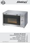
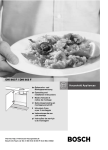
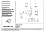
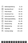
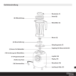
1
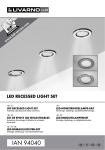
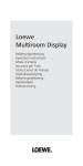
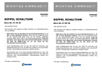
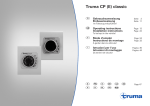
Zeitschaltuhr
ZUE / ZUC 2
Gebrauchsanweisung
Einbauanweisung
2
13
MODIMIDOFRSASO
Seite 6
Seite 8
Gebruiksaanwijzing
Inbouwhandleidding
Operating instructions
Installation instructions
Page 10
Page 12
Brugsanvisning
Monteringsanvisning
Mode d’emploi
Instructions de montage
Page 14
Page 17
Instrucciones de uso
Página 32
Instrucciones de montaje Página 34
Istruzioni per l’uso
Istruzioni di montaggio
Truma Gerätetechnik
GmbH & Co. KG
Wernher-von-Braun-Straße 12
D-85640 Putzbrunn bei München
Pagina 19
Pagina 22
Návod k použití
Návod k montáži
Service
Telefon
Telefax
+49 (0)89 4617-142
+49 (0)89 4617-159
[email protected]
www.truma.com
Pagina 24
Pagina 26
Side 28
Side 30
Strana 36
Strana 38
Schablone für Einbauöffnung
(die Maße B oder C ergeben sich aus den Einbauabbildungen Seite 4 und 5)
Template for cut-out
(the dimensions B or C are derived from the installation illustrations on pages 4 and 5)
Gabarit pour l`orifice de montage
(les dimensions B et C découlent des illustrations de montage, pages 4 et 5)
Sagoma per apertura di montaggio
(le misure B o C si ottengono dalle figure relative all‘installazione alle pagine 4 e 5)
Sjabloon voor inbouwopening
(de maten B of C blijken uit de inbouwafbeeldingen op pagina 4 en 5)
Skabelon til indbygningsåbning
(målene B eller C ses på figurerne side 4 og 5)
Plantilla de montaje para el orificio de montaje
(las medidas B ó C se obtienen a través de las ilustraciones de montaje en páginas 4 y 5)
Šablona pro instalační otvor
(míry B či C vyplývají z montážních obrázků na str. 4 a 5)
2
✂
oben / Top
c
c
R
4
m
m
m
m
c
43 mm
Ø
2,
2
B
B
B
B
c
c
B = 90 mm
c
C = 95 mm
3
A
4
B
C
D
5
Kurzbeschreibung
Die Truma-Zeitschaltuhr
– ZUE, Art.-Nr. 39890-00, und
– ZUE 2, Art.-Nr. 39891-00, für
die Heizungen Trumatic
E 1800, E 2400, E 2800 und
E 4000 (Baureihe 2,
ab Baujahr 1989)
– ZUC 2, Art.-Nr. 34042-01, für
die Heizungen Trumatic
C 3402 und C 6002
ermöglicht ein Vorprogrammieren von 3 Einschaltzeiten innerhalb von 7 Tagen. Die Einschaltdauer ist programmierbar und
liegt bei maximal 2 Stunden. Eine
täglich automatisch wiederkehrende Einschaltung der Heizung
ist nicht möglich.
Diese Zeitschaltuhr darf nicht
zusammen mit den Heizgeräten
Trumatic C 3400/C 6000
Baureihe 1, bis Baujahr 06/97
verwendet werden.
6
4
3
1
2
Gebrauchsanweisung
Die Heizung kann am Bedienteil
und an der Zeitschaltuhr ein- und
ausgeschaltet werden. Wird die
Heizung über die Zeitschaltuhr
bedient, so muss der Schalter am
Bedienteil auf „Aus“ stehen.
2
13
MODIMIDOFRSASO
5
6
7
8
9
1 = Aktuelle Uhrzeit bzw.
Einschaltzeit
2 = Betriebsanzeige
3 = Speicherplatz-Anzeige
4 = Aktueller Wochentag bzw.
Einschalttag
5 = Uhrzeit
6 = Speicherplatz
7 = Sofortheizen
8 = Rücklauf
9 = Vorlauf
Nach einer Unterbrechung der
Stromversorgung (z.B. Ausbau
oder Nachladen von Batterien)
blinkt die Tagesanzeige im Display. Ein Vorprogrammieren der
Heizung ist erst nach dem Einstellen der Zeitschaltuhr möglich.
Sofortstart der Heizung
Unabhängig von der eingestellten Zeit kann die Heizung durch
Betätigen der Taste
ein- oder
ausgeschaltet werden.
Aktuelle Uhrzeit einstellen
Taste
drücken und solange
halten, bis die Anzeige blinkt.
Uhrzeit mit Tasten
oder
einstellen. Nach ca. 5 Sekunden
setzt der Schnellauf ein.
Aktuellen Wochentag
einstellen
Taste
drücken und halten, bis
die Zeit-Anzeige blinkt, nach weiteren ca. 5 Sekunden blinkt die
Tagesanzeige. Mit Tasten oder
den aktuellen Wochentag
einstellen.
Einschaltzeiten
programmieren
Taste
1 x drücken, im Display
erscheint der Speicherplatz 1.
Gewünschte Einschaltzeit mit
den Tasten
oder
einstellen.
Nach ca. 5 Sekunden blinkt die
Tagesanzeige, mit Taste
den
gewünschten Einschalttag einstellen. Taste
nochmals
drücken, die Einschaltzeit ist gespeichert und im Display leuchtet
der Speicherplatz 2. Einschaltzeit
und Einschalttag entsprechend
eingeben und erneut mit Taste
speichern. Im Display leuchtet
nun der Speicherplatz 3. Einschaltzeit und Einschalttag ebenfalls eingeben und nochmals mit
Taste
speichern.
Um bei einer täglich wiederkehrenden Heizzeit
nicht für jeden Wochentag eine
neue Programmierung vornehmen zu müssen, wird auf den
Speicherplätzen 1 und 2 automatisch der nächstmögliche Wochentag angezeigt. Auf dem
Speicherplatz 3 kann der Wochentag explizit eingestellt
werden.
Einschaltzeit aktivieren
Taste
so oft drücken, bis die
gewünschte Einschaltzeit im Display erscheint. Nach kurzer Zeit
schaltet die Uhr automatisch auf
die aktuelle Zeit zurück und der
entsprechende Speicherplatz
wird im Display angezeigt.
Einschaltzeit deaktivieren
Taste
so oft drücken, bis keine
Speicherplatznummer mehr im
Display angezeigt wird.
Einschaltdauer
Taste
drücken. Einschaltdauer
wird angezeigt. Nach ca. 2 Sekunden kann mit den Tasten
oder
die Einschaltdauer
zwischen 1 und 120 Minuten
eingestellt werden. Uhr schaltet
7
automatisch auf aktuelle Uhrzeit
zurück. Nach einer Unterbrechung der Spannungsversorgung
erfolgt die Grundeinstellung von
60 Minuten.
Restlaufzeit
Taste
drücken, Restlaufzeit
wird angezeigt. Nach 2 Sekunden kann die Zeit durch weiteres
Betätigen der Taste
verkürzt
bzw. mit der Taste
verlängert
werden. Die Restlaufzeit wird mit
Taste
gelöscht.
8
Technische Daten
Stromverbrauch
Digitalanzeige:
3 mA
Beleuchtung
12 V: 145 mA
24 V:
75 mA
Kabellänge
Trumatic E:
4m
Trumatic C:
3m
Kabelverlängerungen auf Anfrage
Restlaufanzeige
Taste für sofortige Einschaltung
Die Truma-Zeitschaltuhr wird
von der Heizungselektronik
mit 12 V versorgt (auch bei
der 24 V-Ausführung der
Heizung).
Einbauanweisung
Vor Beginn der Montage
muss die Versorgungsspannung der elektronischen
Steuereinheit abgeklemmt werden! Ausschalten am Bedienteil
reicht nicht! Der Einbau unter
Spannung kann die Zerstörung
der Zeitschaltuhr und der
Heizungselektronik zur Folge
haben!
In Gefahrgutfahrzeugen
(GGVS/ADR) dürfen Zeitschaltuhren nicht betrieben
werden.
Die Montage der Zeitschaltuhr
erfolgt in der Nutzfahrzeug-Ausführung (Art.-Nr. 39890-00) entweder in vorgesehene Öffnungen
im Armaturenbrett (Seite 4:
Bild A) oder mit Einbaurahmen
(Bild B) an geeigneter Stelle.
In der Camping-Ausführung
(Art.-Nr. 39891-00 bzw.
34042-01) erfolgt die Montage
mit Montagerahmen (Bild C),
vorzugsweise im Wohnbereich.
1. Einbauort festlegen und dabei
eine Einbautiefe von mindestens
45 mm berücksichtigen.
Ist eine Unterputzmontage
der Zeitschaltuhr nicht
möglich, liefert Truma als Sonderzubehör einen Aufputzrahmen
(Bild D, Art.-Nr. 39050-11600).
2. Falls erforderlich, die Einbauschablone (Seite 3) entsprechend der vorgesehenen Montage (B oder C) ausschneiden und
über die vorgesehene Einbaustelle kleben. Lochmitte vorstechen
und die Einbauöffnung ausschneiden.
3. Je nach vorgesehener Montage den Einbaurahmen (B) anschrauben oder den Montagerahmen (C) mit den beiliegenden
Klammern an der Uhr befestigen.
4. Kabel an der Uhr anstecken,
durch die Einbauöffnung führen
und zur elektronischen Steuereinheit der Heizung verlegen.
Anschluss der
Beleuchtung
5. Vormontierte Uhr bis zur Einrastung in die Einbauöffnung
schieben (A und B) bzw. Montagerahmen (C) anschrauben.
Soll die Uhr beleuchtet werden
(zusätzlicher Stromverbrauch
bei 12 V: 145 mA), so diese ist
bei 12 V-Anlagen an das gelbe
Kabel des Uhrensteckers 12 V
anzulegen.
6. Deckel der elektronischen
Steuereinheit abschrauben und
die Kabeldurchführung freilegen.
Stecker auf Zubehörstiftleiste
anstecken.
Bei 24 V-Anlagen muss die eingebaute 12 V-Lampe gegen eine
24 V-Lampe ausgetauscht werden (Truma Art.-Nr. 39010-87400
oder im Fachhandel zu beziehen).
Hinweis für Heizungen
Trumatic E: Bei Verwendung
von weiteren Zubehörteilen (z.B.
Fernfühler) ist die Multisteckdose
MSD (Art.-Nr. 39010-78200) zu
verwenden.
Gelbes Kabel mit einem Kabel
(0,75 mm2) verlängern und (bei
Bedarf über einen Schalter) zur
Zentralelektrik (oder Fahrzeugelektrik Klemme 58 „Beleuchtung
Ein“) verlängern.
7. Deckel der elektronischen
Steuereinheit wieder aufschrauben.
Anschlusskabel zur
Beleuchtung mit max.
5 A absichern.
9
Short description
The Truma time-switch
– ZUE, Art. no. 39890-00 and
– ZUE 2, Art. no. 39891-00 for
the heaters Trumatic E 1800,
E 2400, E 2800 and E 4000
(series 2, from year of manufacture 1989)
– ZUC 2, Art. no. 34042-01 for
the heaters Trumatic C 3402
and C 6002
allows a programming of
3 switch-on times within 7 days.
The operating time is programmable up to a maximum of
2 hours. Continuos daily repeats
are not possible.
This timer switch must not be
used in conjunction with
Trumatic C 3400/C 6000 heating
units, Series 1, up to year of
manufacture 06/97.
10
4
3
1
2
Operating
instructions
2
13
The heater can be switched on or
off at the control panel or timer. If
the heater is to be switched on at
the timer the operation switch on
the control panel must be „OFF“.
MODIMIDOFRSASO
5
1
2
3
4
5
6
7
8
9
=
=
=
=
=
=
=
=
=
6
7
8
9
Actual time or switch-on time
Operation
Programme number
Actual day or switch-on time
Key time
Key programme number
Immediate switch-on
Key backwards
Key forwards
Following a interruption of the
power supply (e.g. removing or
charching the battery), the time
on the display flashes. A programming of the heater is only
possible after entering the
current time.
Immediate switch-on
of the heater
Independent of any programmed
time, the heater can be switched
on or off with the key .
Entering the current time
Press the key
and hold until
the display flashes. Set current
time with the keys
or . If
the keys are pressed for longer
than 5 seconds the fast forward
is initiated.
Entering the
current weekday
Press the key
and hold until
the display flushes, after approx.
5 seconds the day indicator
flashes. Set the current weekday
with the keys
or .
Programming the
switch-on times
Press key
once, on the display
the programme number 1 appears.
Enter the requested switch-on
time with the keys
or .
After approx. 5 seconds the
weekday indicator flashes. Enter
the requested switch-on weekday
with key . Press key
once
again to transfer the data to the
memory. On the display appears
programme number 2. Enter the
requested switch-on time and
weekday as before and press key
once again. The programme
number 3 is set as before. After
pressing key
again no programme number shows on the
diplay and the data is in the
memory.
In order to avoid having to
carry out reprogramming
for every weekday in a situation
in which the same heating time
recurs each day, the next possible weekday is automatically displayed on memory spaces 1 and
2. The weekday can be explicitly
set at memory space 3.
Activate switch-on times
Press key
until the requested
switch-on time appears. The display changes automatically back
to current time and the programme number shows on the
display.
Delete switch-on times
Press key
until no switch-on
programme number appears in
the display.
Operating time
Press key . The operating time
shows on the display. After approx. 2 seconds the operating
time can be set with the keys
or . The display changes automatically back to current time.
11
After a interruption of the power
supply the time-switch will set
the basic setting of 60 minutes.
Remaining operating time
Press key , the remaining operating time shows on the display. After approx. 2 seconds the
remaining operating time can be
changed with the keys
or .
The remaining operating time
can be deleted with key .
Technical data
Current input
Digit display:
3 mA
Light
12 V: 145 mA
24 V:
75 mA
Cable lengths:
Trumatic E:
4m
Trumatic C:
3m
Cable extensions on request
Display of the remaining
running time
Key for immediate switch-on of
the heater
The Truma time-switch receives it 12 V power supply
from the heater-electronics
(also with the 24 V version
heaters).
12
Installation instructions
During works the current
supply of the heater must
be disconnected. It is not enough
to switch the heater off at the
control panel. Connecting under
power can destroy the timeswitch and the heater-electronics!
In commercial vehicles which
transport dangerous goods
according (GGVS/ADR) the
use of a time-switch is not
permitted.
The timer switch is to be installed
in the commercial vehicle format
(Art. no. 39890-00), either in the
apertures provided for in the
dashboard (page 4; fig. A) or
with an installation frame (fig. B)
at a suitable location.
In the camping design format
(Art. no. 39891-00 or 34042-01
respectively), installation is
effected with an installation
frame (fig. C), for preference in
the living area.
1. Locate a convenient place with
a fitting depth of at least 45 mm.
If it is not possible to install
the timer flush with the
surface, Truma can provide a
surface-mounting frame as a
special accessory (fig. D,
Art. no. 39050-11600).
2. If required, cut out the installation template (page 3) corresponding to the installation type
provided for (B or C), and glue it
above the intended installation
location. Make the preliminary
perforation of the centre hole and
cut out the installation aperture.
3. Depending on the type of installation planned, screw the installation frame (B) in place, or
secure the installation frame (C)
to the timer switch with the
clamps provided.
4. Plug the cable in at the clock,
guide it through the installation
aperture, and lay it to the electronic control unit of the heating
system.
5. Push the pre-fitted timer switch
into the installation aperture until
it engages (A and B), or screw
on the installation frame (C).
6. Unscrew the cover of the electronic control unit and expose
the cable passage. Insert the
plug into the accessory pin strip.
Note for Trumatic E heating
systems: If additional accessory
items are being used (e.g. remote sensor), the MSD multi-pin
socket is to be used (Art. no.
39010-78200).
7. Screw the cover of the electronic control unit back on again.
Light connection
If it is intended for the clock to be
illuminated (additional current
consumption at 12 V; 145 mA),
then, with 12 V systems, 12 V is
to be applied to the yellow cable
of the clock plug.
With 24 V systems, the 12 V
lamp fitted must be replaced by
a 24 V lamp (Truma Art. no.
39010-87400 or available from
specialist dealers).
Extend the yellow cable with a
cable measuring 0.75 mm2 and
(if necessary, via a switch) run it
to the central electrical system
(or the vehicle electrical system,
terminal 58 „Lighting On“).
Fuse capacity is max.
5 A for the connection
cable for the lighting.
13
Description générale
L'automate temporisé Truma
– ZUE, n° d’art. 39890-00 et
– ZUE 2, n° d’art. 39891-00
pour les chauffages Trumatic
E 1800, E 2400, E 2800 et
E 4000
(2ème série de fabrication,
fabriqués à partir de 1989)
– ZUC 2, n° d’art. 34042-01
pour les chauffages Trumatic
C 3402 et C 6002
permet de préalablement programmer 3 heures d'allumage
différentes sur une période de
7 jours. La durée de marche peut
aussi être programmée et sera de
2 heures au maximum. On ne
peut cependant pas faire en sorte
que le chauffage s'allume automatiquement tous les jours à la
même heure.
Cette minuterie ne doit pas être
utilisée avec les appareils de
14
chauffage Trumatic C 3400/
C 6000, issus de la gamme de
fabrication 1 et fabriqués avant
le 06/97.
4
3
1
2
2
13
MODIMIDOFRSASO
5
6
7
8
9
1 = Heure actuelle et/ou heure
d'allumage
2 = Indication de service
3 = Indication de la zone de
mémoire
4 = Jour de la semaine actuel
et/ou jour d'allumage
5 = Heure
6 = Zone de mémoire
7 = Chauffage instantané
8 = Marche arrière
9 = Marche avant
Mode d’emploi
Le chauffage peut être allumé et
éteint à la pièce de commande
et à l'automate temporisé. Si la
marche du chauffage est commandée par l'intermédiaire de
l'automate temporisé, l'interrupteur de la pièce de commande
doit être sur « Arrêt ».
En cas d'une interruption de l'alimentation en courant (par ex.
pour changer ou recharger les
piles), l'indication du jour clignote
au terminal de visualisation. La
programmation préalable du
chauffage ne pourra s'effectuer
qu'après le réglage de l'automate
temporisé.
Mise en service
instantanée du chauffage
tard. Régler le jour de la semaine
actuel avec les touches
ou .
Indépendamment du temps réglé, le chauffage peut être allumé
ou éteint en appuyant sur la
touche .
Programmation des
heures d'allumage
Réglage de l'heure actuelle
Appuyer sur la touche
jusqu'à
ce que l'indication clignote. Régler l'heure avec les touches
ou . La vitesse rapide des
chiffres de la montre se déclenchera environ 5 secondes plus tard.
Réglage du jour de
la semaine actuel
Appuyer sur la touche
jusqu'à
ce que l'indication de l'heure
clignote, l'indication du jour clignotera environ 5 secondes plus
Appuyer une fois sur la touche
et la zone de mémoire apparaît
au terminal de visualisation 1.
Régler l'heure d'allumage désirée
avec les touches
ou . L'indication du jour clignote environ
5 secondes plus tard, régler le
jour d'allumage désiré avec la
touche . Appuyer une nouvelle
fois sur la touche , le temps
d'allumage est mémorisé et la zone de mémoire 2 s'allume au terminal de visualisation. Introduire
l'heure et le jour d'allumage désirés et remémoriser avec la
touche . La zone de mémoire 3
s'allume à présent au terminal
de visualisation, introduire à nouveau l'heure et le jour d'allumage
désirés et remémoriser une
dernière fois avec la touche .
Afin de ne pas recommencer, tous les jours de la semaine, la programmation d’une
période de chauffage quotidienne toujours identique, le jour de
la semaine le plus proche s’affiche sur les emplacements de
mémoire 1 et 2. Sur l’emplacement de mémoire 3, il est possible de régler précisément le
jour de la semaine souhaité.
Activation de l’heure
d’allumage
Appuyer sur la touche
jusqu’à
ce que l’heure d’allumage désirée apparaisse au terminal de
visualisation. Peu de temps plus
tard, la montre retourne automatiquement à l’heure actuelle et
la zone de mémoire correspondante apparaît au terminal de
visualisation.
15
Désactiver l’heure
d’allumage
Appuyer aussi longtemps sur la
touche
jusqu’à ce qu’il n’apparaisse plus de zone de mémoire au terminal de visualisation.
Durée de marche
Appuyer sur la touche
. La durée de marche s’affiche. Environ
2 secondes plus tard, on peut régler la durée de marche entre 1
et 120 minutes avec les touches
et . La montre retourne automatiquement à l’heure actuelle.
Après une interruption de
l’alimentation en courant s’effectuera un réglage de base de
60 minutes.
16
Temps de marche résiduel
Appuyer sur la touche . Le
temps de marche résiduel s’affiche. Environ 2 secondes plus
tard, on peut le réduire en appuyant à nouveau sur la touche
ou le prolonger avec la
touche . Pour effacer le temps
de marche résiduel, appuyer sur
la touche .
Caractéristiques
techniques
Consommation de courant
Indication numérique :
3 mA
Eclairage
12 V : 145 mA
24 V :
75 mA
Longueur de câbles:
Trumatic E :
4m
Trumatic C :
3m
Rallonge de câbles sur demande
Indication de marche résiduelle
Touche d’allumage instantané
L’automate temporisé Truma
est alimenté en courant 12 V
par le système électronique
du chauffage (même pour un
modèle de chauffage à 24 V).
Instructions de montage
Avant de procéder au
montage, débrancher
l’alimentation en courant du module de commande électrique ! Il
ne suffit pas d’éteindre la pièce
de commande ! Tout montage
sous tension pourrait causer la
destruction de l’automate temporisé et du système électronique
du chauffage !
L’emploi d’automates temporisés est interdit dans les
véhicules de transport de
marchandises dangereuses
(R.I.D./ADR).
L’installation du modèle de minuterie pour véhicule utilitaire
(n° d’art. 39890-00) s’effectue
soit dans les ouvertures prévues
à cet effet sur le tableau de bord
(page 4 : fig. A), soit à un
endroit adapté avec un cadre
d’encastrement (fig. B).
Pour le modèle Camping (n° d’art.
39891-00 et 34042-01), l’installation s’effectue avec un cadre de
montage (fig. C), de préférence
dans l’espace habitable.
3. Selon le type de montage envisagé, visser le cadre d’encastrement (B) ou bien fixer le cadre de
montage (C) sur la minuterie avec
les brides de fixation fournies.
1. Déterminer l’emplacement
pour le montage et y prévoir une
profondeur d’encastrement d’au
moins 45 mm.
4. Raccorder le câble sur la minuterie, le faire passer par l‘ouverture de montage et le poser jusqu‘à
l‘unité de commande électronique du chauffage.
S’il n’est pas possible
d’encastrer la minuterie,
Truma met à votre disposition,
à titre d’accessoire spécial, un
cadre de montage sur socle
(fig. D, n° d’art. 39050-11600).
2. Si cela est nécessaire, découper le gabarit de montage
(page 3) en fonction du montage
envisagé (B ou C) et le coller
sur l’emplacement prévu pour
l’installation. Percer au préalable
le centre du trou et découper
l’orifice de montage.
5. Faire glisser la minuterie préassemblée jusqu’à ce qu’elle s’enclenche dans l’orifice de montage (A et B) ou bien visser le
cadre de montage (C).
6. Dévisser le couvercle de l‘unité
de commande électronique et
mettre à nu le passe-câble. Brancher la prise sur la baguette
réservée aux broches des
accessoires.
17
Remarque pour les chauffages Trumatic E : si vous branchez d‘autres accessoires (par
ex.: des sondes à distance), il est
nécessaire d‘utiliser la prise multiple MSD (n° d‘art. 39010-78200).
7. Revisser le couvercle de l‘unité
de la commande électronique.
Raccordement
de l’éclairage
Si la minuterie doit être éclairée
(consommation de courant supplémentaire sur les 12 V :
145 mA), il faut brancher, sur les
installations de 12 V, la prise de
la minuterie sur le câble jaune.
Pour les installations alimentées
en 24 V, la lampe 12 V incorporée doit être remplacée par une
lampe 24 V (n° d’art. Truma
39010-87400 ou à acheter en
magasin spécialisé).
18
Possibilité de rallonger le câble
jaune avec un câble de 0,75 mm2
et de le tirer (en cas de besoin
via un commutateur) jusqu’à
l’électricité centrale (ou jusqu’à
l’électricité du véhicule, borne
de connexion 58 « Eclairage
Marche ».
Le câble de connexion
de l’éclairage doit être
protégé par un fusible de 5 A
max.
Breve descrizione
L'interruttore orario della Truma
– ZUE, n° art. 39890-00 e
– ZUE 2, n° art. 39891-00
per i riscaldamenti
Trumatic E 1800, E 2400,
E 2800 e E 4000 serie di costruzione 2, staccato all‘anno
di fabbricazione 1989)
– ZUC 2, n° art. 34042-01 per
i riscaldamenti Trumatic
C 3402, e C 6002
permette la preprogrammazione
di 3 tempi d'inserzione in una settimana. La durata d'inserzione è
programmabile ed è al massimo
2 ore. Una inserzione che si ripeta giornalmente in modo automatico non è possibile.
Questo orologio temporizzatore
non deve essere utilizzato con le
stufe Trumatic C 3400/C 6000,
variante di serie 1, fino all‘anno
di fabbricazione 06/97.
4
3
1
2
Istruzioni per l’uso
2
13
MODIMIDOFRSASO
5
6
7
8
9
1 = Orario attuale o risp. orario
d'inserzione
2 = Indicazione di
funzionamento
3 = Indicazione della memoria
4 = Giorno della settimana
attuale o risp. giorno
d'inserzione
5 = Orario
6 = Memoria
7 = Riscalmento immediato
8 = Ritorno
9 = Andata
Il riscaldamento può venire acceso o spento sulla unità di comando o sull'interruttore orario. Se il
riscaldamento viene comandato
mediante interruttore orario, l'interruttore sulla unità di comando
deve trovarsi in posizione „OFF“.
In seguito ad un'interruzione dell'alimentazione di corrente (p.e.
per ampliamento o ricarica delle
batterie) sul display lampeggia la
visualizzazione del giorno. Una
preprogrammazione del riscaldamento è possibile solamente
dopo aver regolato l'interruttore
orario.
19
Avvio immediato
del riscaldamento
Indipendentemente dall'orario
impostato, il riscaldamento può
venire acceso o spento mediante
azionamento del tasto .
Regolazione
dell'orarIo attuale
Premere il tasto
e tenerlo premuto fino al lampeggiamento
della visualizzazione. Impostare
l'orario servendosi dei tasti
o
. Dopo ca. 5 secondi comincia
il funzionamento rapido.
Regolazione del giorno
della settimana attuale
Premere il tasto
e tenerlo
premuto finchè l'indicazione del
tempo lampeggi; dopo ulteriori
20
ca. 5 secondi lampeggia l'indicazione del giorno. Servendosi dei
tasti
o
impostare il giorno
attuale.
Programmazione degli
orari di inserzione
Premendo una volta il tasto
,
sul display appare la memoria 1.
Impostare servendosi dei tasti
o
l'orario di inserzione desiderato. Dopo ca. 5 secondi l'indicazione del giorno lampeggia, con
il tasto
impostare il giorno desiderato. Premere nuovamente il
tasto : l'orario di inserzione è
memorizzato e sul display si accende la memoria 2. Introdurre
orario e giorno di inserzione e
memorizzare nuovamente con il
tasto . Sul display si accende
ora la memoria 3. Introdurre
anche qui orario e giorno di
inserzione e memorizzare nuovamente con il tasto .
Per non dover eseguire
una nuova programmazione per ogni giorno della settimana qualora l'orario di riscaldamento si ripeta quotidianamente,
nelle posizioni di memoria 1 e 2
viene indicato automaticamente
il giorno settimanale successivo.
Nella posizione di memoria 3
possono esser impostati orari
specifici per un determinato
giorno della settimana.
Attivazione
dell'orario d'inserzione
Premere il tasto
finchè appare
sul display l'orario d'inserzione
desiderato. Dopo un breve periodo, l'orologio ritorna automaticamente all'orario attuale e la memoria corrispondente viene
visualizzata sul display.
Disattivazione
dell'orario d'inserzione
Tempo rimanente
di funzionamento
Premere il tasto
finchè non
venga visualizzato nessun numero di memoria sul display.
Premendo il tasto , viene
visualizzato il tempo di funzionamento rimanente. Dopo 2 secondi il tempo può venire ridotto
azionando nuovamente il tasto
o risp. prolungato con il
tasto
. Il tempo rimanente di
funzionamento viene cancellato
con il tasto .
Durata d'inserzione
Premere il tasto . Viene visualizzata la durata d'inserzione. Dopo ca. 2 secondi è possibilere impostare con i tasti
o
una
durata d'inserzione compresa tra
1 e 120 minuti. L'orologio ritorna
automaticamente all'orario attuale. Dopo un'interruzione dell'alimentazione di corrente segue una
regolazione di base di 60 minuti.
Dati tecnici
Consumo di corrente
Visualizzazione digitale: 3 mA
Illuminazione 12 V: 145 mA
24 V:
75 mA
Lunghezza del cavo:
Trumatic E:
4m
Trumatic C:
3m
Prolungamento del cavo dietro
richiesta
Visualizzazione del funzionamento rimanente
Tasto per inserzione immediata
L'interruttore orario della
Truma viene alimentato
dall'elettronica del riscaldamento con 12 V (anche in
caso di esecuzione a 24 V
del riscaldamento).
21
Istruzioni di montaggio
Prima di iniziare il montaggio, staccare la tensione d'alimentazione dell'unità di
comando elettrica! Non è sufficiente la disinserzione sulla unità
di comando! Il montaggio sotto
tensione può provocare la distruzione dell'interruttore orario e
dell'elettronica del riscaldamento!
Interruttori orari non devono
venire azionati su automezzi
per il trasporto di materiali
pericolosi (GGVS/ADR).
Nelle versioni per veicoli commerciali (n° art. 39890-00) l‘orologio temporizzatore viene montato
nelle aperture previste sul quadro
portastrumenti (pagina 4:
figura A) oppure con telaio di
installazione (figura B) in una
posizione idonea.
22
Nelle versioni per veicoli da campeggio (n° art. 39891-00 o
34042-01) l‘orologio viene montato con telaio di installazione
(figura C), preferibilmente
nell‘abitacolo.
3. A seconda del tipo di installazione prevista avvitare il telaio di
installazione (B) oppure fissare il
telaio di montaggio (C) all‘orologio con le graffe fornite in dotazione.
1. Determinare il luogo del montaggio e considerare una profondità di montaggio di ca. 45 mm.
4. Fissare il cavo all'orologio, farlo
passare attraverso l'apertura di
installazione e portarlo fino alla
centralina elettronica della stufa.
Se non è possibile un
montaggio incassato
dell‘orologio temporizzatore,
Truma fornisce come accessorio
speciale un telaio per montaggio
non incassato (figura D, n° art.
39050-11600).
2. Se necessario, ritagliare la dima di montaggio (pagina 3) in
base all‘installazione prevista
(B o C) e incollarla sul punto previsto per il montaggio. Praticare
dapprima un foro al centro e ritagliare l‘apertura per il montaggio.
5. Spingere (A e B) l‘orologio
montato in precedenza fino a incastrarlo nell‘apertura praticata
per il montaggio ovvero avvitare
il telaio di montaggio (C).
6. Svitare il coperchio della centralina elettronica e scoprire il
passacavo. Fissare la spina sul
connettore ad innesto accessorio.
Nota per le stufe Trumatic E:
In caso di impiego di ulteriori accessori (ad es. sensore a distanza), utilizzare una presa multipla
MSD (n° art. 39010-78200).
7. Riavvitare il coperchio della
centralina elettronica.
Collegamento
dell'illuminazione
Per il cavo di collegamento per l'illuminazione utilizzare un fusibile da 5 A
max.
Nel caso in cui si debba illuminare l'orologio (consumo elettrico
aggiuntivo a 12 V: 145 mA), per
gli impianti a 12 V applicare al
cavo giallo della spina dell'orologio una tensione di 12 V.
Negli impianti a 24 V la spia luminosa da 12 V incorporata deve
essere sostituita con una spia
luminosa da 24 V (Truma n° art.
39010-87400 o acquistabile
presso i rivenditori specializzati).
Applicare una prolunga da
0,75 mm2 al cavo giallo (se necessario, mediante un interruttore) e portarlo fino all'impianto
elettrico centrale (o all'impianto
elettrico del veicolo, morsetto 58
„Illuminazione On“).
23
Korte omschrijving
De Truma-tijdschakelklok
– ZUE, art.-nr. 39890-00 en
– ZUE 2, art.-nr. 39891-00
voor de kachels Trumatic
E 1800, E 2400, E 2800 en
E 4000 (bouwserie 2, af
bouwjaar 1989)
– ZUC 2, art.-nr. 34042-01 voor
de kachels Trumatic C 3402,
en C 6002
maakt een voorprogrammeren
van 3 inschakeltijden binnen
7 dagen mogelijk. De inschakelduur is programmeerbaar en ligt
bij maximaal 2 uur. Een dagelijks
automatisch terugkerende inschakeling van de kachel is niet
mogelijk.
Deze tijdschakelklok mag niet samen met de verwarmingstoestellen Trumatic C 3400/C 6000, serie 1, tot bouwjaar 06/97 gebruikt
worden.
24
4
3
1
2
Brugsanvisning
2
13
MODIMIDOFRSASO
5
6
7
8
9
1 = Actueel tijdstip resp.
inschakeltijd
2 = Bedrijfsaanwijzing
3 = Geheugenplaats-aanwijzing
4 = Actuele weekdag resp.
inschakeldag
5 = Tijdstip
6 = Geheugenplaats
7 = Direct verwarmen
8 = Terugloop
9 = Voorloop
De kachel kan aan het bedieningspaneel en aan de tijdschakelklok
worden in- en uitgeschakeld.
Wordt de kachel via de tijdschakelklok bediend, dan moet de
schakelaar aan het bedieningspaneel op „Uit“ staan.
Na een onderbreking van de
stroomtoevoer (bij voorbeeld uitbouw of naladen van batterijen)
knippert de dag-aanwijzing in het
display. Een voorprogrammeren
van de kachel is pas na het instellen van de tijdschakelklok
mogelijk.
Directe start van de kachel
Onafhankelijk van de ingestelde
tijd kan de kachel door bedienen
van de toets
worden in- of
uitgeschakeld.
Actueel tijdstip instellen
Toets
drukken en zo lang houden totdat de aanwijzing knippert. Tijdstip met de toetsen
en
instellen. Na ongeveer
5 seconden begint de snelloop.
Actuele weekdag instellen
Toets
drukken en houden totdat de tijdaanwijzing knippert; na
verdere ongeveer 5 seconden
knippert de dagaanwijzing. Met
de toetsen
en
de actuele
weekdag instellen.
Inschakeltijden
programmeren
Toets
1 x drukken, in het display verschijnt de geheugenplaats 1. Gewenste inschakeltijd
met de toetsen
en
instellen. Na ongeveer 5 seconden
knippert de dagaanwijzing, met
toets
de gewenste inschakeldag instellen. Toets
nogmaals
drukken, de inschakeltijd is opgeslagen en in het display licht de
geheugenplaats 2. Inschakeltijd
en inschakeldag overeenkomstig
invoeren en opnieuw met toe
opslaan. In het display licht
nu de geheugenplaats 3. Inschakeltijd en inschakeldag eveneens
invoeren en nogmaals met toets
opslaan.
Inschakeltijd activeren
Om bij een dagelijks zich
herhalende verwarmtijd
niet voor iedere weekdag een
nieuwe programmering te moeten uitvoeren, wordt op de geheugenplaatsen 1 en 2 automatisch de eerstvolgende weekdag
weergegeven. Op geheugenplaats 3 kan de weekdag
expliciet worden ingesteld.
Toets
zo dikwijls drukken totdat geen geheugenplaats-nummer meer in het display wordt
aangewezen.
Toets
zo dikwijls drukken totdat de gewenste inschakeltijd in
het display verschijnt. Na korte
tijd schakelt de klok automatisch
naar de actuele tijd terug en de
overeenkomstige geheugenplaats wordt in het display
aangewezen.
Inschakeltijd deactiveren
Inschakelduur
Toets
drukken. Inschakelduur
wordt aangewezen. Na ongeveer
2 seconden kan met de toetsen
of
de inschakelduur tussen
25
1 en 120 minuten worden ingesteld. De klok schakelt automatisch naar het actuele tijdstip
terug. Na een onder-breking van
de spannings-toevoer vindt de
basisinstelling van 60 minuten
plaats.
Restlooptijd
Toets
drukken. Restlooptijd
wordt aangewezen. Na 2 seconden kan de tijd, door de toets
opnieuw te drukken, worden verkort resp. met de toets
worden verlengd. De restlooptijd
wordt met de toets
gewist.
26
Technische gegevens
Stroomverbruik
Digitale aanwijzing:
Verlichting
12 V:
24 V:
3 mA
145 mA
75 mA
Kabellengte:
Trumatic E:
4m
Trumatic C:
3m
Kabelverlenging op aanvraag
Restloopaanwijzing
Toets voor directe inschakeling
De Truma tijdschakelklok
wordt door de verwarmingselek-tronica met 12 V gevoed
(ook bij de 24 V-versie van
de kachel).
Monteringsanvisning
Vóór het begin van de
montage moet de voedingsspanning van de elektrische
besturingseenheid worden afgeklemd! Het uitschakelen aan het
bedieningselement is niet voldoende! De inbouw onder spanning kan de vernieling van de
tijdschakelklok en de verwarmingselektronica tot gevolg
hebben!
In voertuigen voor het transport van gevaarlijke goederen
(GGVS/ADR) mogen tijdschakelklokken niet worden
gebruikt.
De montage van de tijdschakelklok geschiedt in de bedrijfswagen-uitvoering (art.-nr. 39890-00)
in hiervoor bestemde openingen
in het dashboard (pagina 4:
afb. A) óf met inbouwframe
(afb. B) op een geschikte plek.
In de camping-uitvoering (art.-nr.
39891-00 resp. 34042-01) geschiedt de montage met montageframe (afb. C), bij voorkeur in
het woongedeelte.
1. Inbouwplaats vastleggen en
daarbij op een inbouwdiepte van
minstens 45 mm letten.
Is een inbouwmontage
van de tijdschakelklok
niet mogelijk, dan levert Truma
als speciaal toebehoren een
opbouwframe (afb. D, art.-nr.
39050-11600).
2. Indien nodig de inbouwsjabloon (pagina 3) overeenkomstig
de geplande montage (B of C)
uitknippen en over de geplande
inbouwplek plakken. Midden
van het gat voorsteken en de
inbouwopening uitzagen.
3. Al naargelang geplande montage het inbouwframe (B) erop
schroeven of het montageframe
(C) met de bijgevoegde klemmen
aan de klok bevestigen
Aansluiting van
de verlichting
4. Kabel in de klok steken, door
de inbouwopening leiden en naar
de elektronische regeleenheid
van de verwarming verleggen.
Indien de klok verlicht dient te
worden (extra stroomverbruik
bij 12 V: 145 mA), moet bij
12 V-installaties de gele kabel
van de klokstekker 12 V worden
aangelegd.
5. Voorgemonteerde klok in de
inbouwopening schuiven tot deze vastklikt (A en B) resp. montageframe (C) erop schroeven.
6. Deksel van de elektronische
regeleenheid losschreoven en
de kabeldoorvoering vrijleggen.
Stekker op de uitrustingsaansluitschema steken.
Opmerking voor verwarmingen Trumatic E: Bij gebruik van
verdere uitrustingsonderdelen
(b.v. afstandvoeler) dient het multistopcontact MSD (art.-nr. 3901078200) te worden toegepast.
7. Deksel van de elektronische
regeleenheid weer vastschroeven.
Bij 24 V-installaties moet de ingebouwde 12 V-lamp vervangen
worden door een 24 V-lamp
(Truma art.-nr. 39010-87400 of
verkrijgbaar in speciaalzaak).
Geel kabel met een kabel
0,75 mm2 verlengen en (indoen
nodig via een schakelaar) naar de
centrale elektrische kast (of voertuigelectronica contact 58
„Verlichting aan“) verlengen.
Aansluitkabel ter verlichting met max. 5 A
beveiligen.
27
Kort beskrivelse
Truma Tænd-sluk-uret
– ZUE, art.-nr. 39890-00 og
– ZUE 2, art.-nr. 39891-00
til opvarmningerne Trumatic
E 1800, E 2400, E 2800 og
E 4000 (serie 2, bort serie 1989)
– ZUC 2, art.-nr. 34042-01 til
opvarmningerne Trumatic
C 3402 og C 6002
gør det muligt at forprogrammere 3 indkoblingstider i løbet af 7
dage. Indkoblingsvarigheden kan
programmeres og ligger på maksimalt 2 timer. En dagligt tilbagevendende automatisk indkobling
af opvarmningen er ikke mulig.
Timeren må ikke anvendes sammen med varmeanlæggene
Trumatic C 3400/C 6000, serie 1
til og med serie 06/97.
28
4
3
1
2
Brugsanvisning
2
13
MODIMIDOFRSASO
5
6
7
8
9
1 = Det aktuelle klokkeslæt
hhv. indkoblingstiden
2 = Driftsvisning
3 = Lagerplads-visning
4 = Den aktuelle ugedag
hhv. indkoblingsdagen
5 = Klokkeslæt
6 = Lagerplads
7 = Øjeblikkelig opvarmning
8 = Returløb
9 = Fremløb
Opvarmningen kan tændes og
slukkes over betjeningsdelen og
på tænd-sluk-uretv. Hvis opvarmningen betjenes over tænd-slukuret, skal kontakten på betjeningsdelen stå på „slukket“.
Efter en afbrydelse af strømforsyningen (f.eks. afmontering eller
efteropladning af batterierne)
blinker dagsvisningen på displayet. En forprogrammering af opvarmningen er først mulig, når
tænd-sluk-uret er indstillet.
Øjeblikkelig start af
opvarmningen
Opvarmningen kan tændes eller
slukkes ved at trykke på tasten
, uafhængigt af den indstillede
tid.
Indstilling af det
aktuelle klokkeslæt
Tryk på tasten
og hold den
trykket, indtil visningen blinker.
Indstil klokkeslættet med tasterne
eller
. Efter ca. 5 sekunder begynder hurtigløbet.
Indstilling af den
aktuelle ugedag
Tryk på tasten
og hold den
trykket, indtil tids-visningen blinker; efter yderligere ca. 5 sekunder blinker dagsvisningen. Indstil
den aktuelle ugedag med tasterne
eller
.
Programmering af
indkoblingstider
Tryk 1 x på taste ; på displayet
vises lagerplads 1. Indstil den
ønskede indkoblingstid med
tasterne
eller
. Efter ca.
5 sekunder blinker dags-visningen; indstil den ønskede indkoblingsdag med taste
. Tryk på
taste
en gang til, så er indkoblingstiden lagret. På displayet lyser lagerplads 2. Indlæs indkoblingstid og indkoblingsdag på
samme måde og bekræft det igen
med taste . På displayet lyser
så lagerplads 3. Denne indkoblingstid og indkoblingsdag indlæses ligeledes og bekræftes
igen med taste .
Aktivering af
indkoblingstiden
For ikke at skulle foretage
en ny programmering for
hver ugedag ved en daglig tilbagevendende opvarmningstid vises den næstmulige ugedag automatisk på pladserne 1 og 2. På
plads 3 kan ugedagen indstilles
direkte.
Tryk så mange gange på tasten
, til der ikke vises noget lagerpladsnummer mere på displayet.
Tryk så mange gange på tasten
, til den ønskede indkoblingstid vises på displayet. Efter kort
tid skifter uret automatisk tilbage
til den aktuelle tid, og den
tilsvarende lagerplads vises på
displayet.
Deaktivering af
indkoblingstiden
Indkoblingsvarighed
Tryk på tasten
. Så vises indkoblingsvarigheden. Efter ca.
2 sekunder kan indkoblingsvarigheden ved hjælp af tasterne
eller
indstilles på mellem
29
1 og 120 minutter. Uret skifter
automatisk tilbage til det aktuelle
klokkeslæt. Når spændingsforsyningen har været afbrudt, stilles
over på grundindstillingen på
60 minutter.
Resterende driftstid
Tryk på tasten
, så vises den
resterende driftstid. Efter 2 sekunder kan tiden forkortes ved
at trykke på tasten
igen eller
forlænges med tasten
. Den
resterende driftstid slettes med
tasten .
Tekniske data
Strømforbrug
Digitaldisplay:
3 mA
Belysning
12 V: 145 mA
24 V:
75 mA
Kabellængde
Trumatic E:
4m
Trumatic C:
3m
Kabelforlænger på forespørgsel
Monteringsanvisning
Inden monteringen påbegyndes, skal den elektriske styreenhed skilles fra forsynings-spændingen! Det er ikke
nok at slukke på betjeningsdelen!
En indbygning under spænding
kan medføre, at tænd-sluk-uret
og varmeelektronikken bliver
ødelagt!
Display over resterende driftstid
Taste til øjeblikkelig indkobling
Truma tænd-sluk-uret får
tilført 12 V af opvarmningselektronikken (også ved en
24 V-udførelse af opvarmningen).
I køretøjer til farligt gods
(GGVS/ADR) må der ikke
benyttes tændslukure.
Timeren, der er fremstillet til
nyttevogne (art.-nr. 39890-00),
monteres i de hertil beregnede
åbninger på instrumentbrættet
(side 4: figur A) eller vha. monteringsramme (figur B) på et
egnet sted.
Timeren, der er fremstillet til
camping (art.-nr. 39891-00
eller 34042-01), monteres vha.
30
monteringsramme (figur C), fortrinsvis i opholdsafdelingen.
1. Fastlæg indbygningsstedet og
tag derved hensyn til en indbygningsdybde på mindst 45 mm.
Hvis indbygning af timeren
ikke er mulig, kan Truma
levere en ramme (figur D,
art.-nr. 39050-11600) som ekstra
tilbehør.
2. Ved behov klippes en monteringskabelon (side 3) iht. den
planlagte montering (B eller C)
og klæbes på selve indbygningsstedet. Stik hul i skabelonens midte og klip indbygningsåbningen
ud.
3. Afhængig af den planlagte
montering skrues rammen (B) på
eller monteringsrammen (C) fastgøres til timeren vha. de vedlagte
klemmer.
4. Tilslut kablet til uret, før det
gennem monteringsåbningen og
træk det hen til opvarmningsanlæggets elektroniske styreenhed.
5. Den formonterede timer skubbes ind i indbygningsåbningen,
indtil den går i hak (A og B), og
monteringsrammen (C) skrues
fast.
6. Skru dækslet for den elektroniske styreenhed af og frilæg kabelgennemføringen. Tilslut stikket på tilbehørsstiftlisten.
Bemærk for opvarmningsanlæg Trumatic E: Ved anvendelse
af yderligere tilbehørsdele (f.eks.
fjernfølere) skal multistik-dåse
MSD (art.-nr. 39010-78200)
anvendes.
7. Skru den elektroniske styreenheds dæksel på igen.
Tilslutning af belysningen
Hvis uret skal belyses (ekstra
strømforbrug ved 12 V: 145 mA),
så skal der i forbindelse med
12 V-anlæg være 12 V ved
urstik-kets gule kabel.
Ved 24 V anlæg skal den integrerede 12 V lampe udskiftes med
en 24 V lampe (Truma art.-nr.
39010-87400 eller fås hos
specialforretninger).
Det gule kabel forlænges med et
kabel 0,75 mm2 og (ved behov
via en kontakt) forlænges til det
centrale elektriske anlæg (eller
køretøjets elektriske anlæg
klemme 58 „Belysning Til“).
Tilslutningskabel til
belysning afsikres
med maks. 5 A.
31
Descripción resumida
Los relojes temporizadores Truma
– ZUE, nº de art. 39890-00 y
– ZUE 2, nº de art. 39891-00
para las calefacciones Trumatic
E 1800, E 2400, E 2800 y
E 4000 (serie de fabricación 2,
a partir del año de fabricación
1989)
– ZUC 2, nº de art. 34042-01
para las calefacciones Trumatic
C 3402 y C 6002
permiten la programación previa
de 3 tiempos de conexión en un
término de 7 días. La duración de
la conexión es programable hasta máximo 2 horas. No es posible
repetir automáticamente cada día
una conexión de la calefacción.
Este reloj temporizador no debe
utilizarse junto con los aparatos
de calefacción Trumatic C 3400/
C 6000, serie de fabricación 1,
hasta el año de fabricación 06/97.
32
4
3
1
Instrucciones de uso
2
2
13
MODIMIDOFRSASO
5
6
7
8
9
1 = Hora actual o tiempo de
conexión
2 = Indicador de funcionamiento
3 = Indicador de posición de
memoria
4 = Actual día de semana o día
de conexión
5 = Hora
6 = Posición de memoria
7 = Calefacción inmediata
8 = Retroceso
9 = Avance
La calefacción se puede encender y apagar en la unidad de
mando y con el reloj temporizador. Si la calefacción se maneja a
través del reloj temporizador, el
conmutador en la unidad de mando debe estar en „Desconectar“.
Después de una interrupción de
la fuente de alimentación (p.ej. al
desmontar o cargar las baterías)
el indicador del día parpadea en
el display. La programación previa de la calefacción es sólo posible después que se ha ajustado
el reloj temporizador.
Arranque inmediato
de la calefacción
Independiente del tiempo ajustado, la calefacción se puede encender o apagar pulsando la
tecla .
Ajuste de la hora actual
Pulsar la tecla
y mantenerla
pulsada tanto tiempo, hasta que
el indicador parpadee. Ajustar la
hora con las teclas
o
. La
marcha rápida se inicia después
de aprox. 5 segundos.
Ajuste del actual día
de semana
Pulsar la tecla
y mantenerla
pulsada tanto tiempo, hasta que
el indicador de tiempo parpadee.
Después de aprox. 5 segundos
parpadea el indicador del día.
Ajustar con las teclas
o
el
actual día de semana.
Programación de los
tiempos de conexión
Pulsar la tecla
1 vez, en el
display aparece la posición de
memoria 1. Ajustar el tiempo de
conexión requerido con las teclas
o
. El indicador del día parpadea después de aprox. 5 segundos, ajustar con la tecla
el
día de conexión deseado. Pulsar
la tecla
otra vez, el tiempo de
conexión está memorizado y en
el display luce la posición de memoria 2. Entrar el tiempo y el día
de conexión respectivamente
y memorizar de nuevo con la
tecla . En el display luce ahora
la posición de memoria 3. Entrar
igualmente el tiempo y el día de
conexión, y memorizar de nuevo
con la tecla .
A fin de no tener que efectuar ninguna nueva programación para cada día de
semana de un tiempo de calefacción que se repite cada día, en
las posiciones de memoria 1 y 2
se indica automáticamente el siguiente día de semana posible.
El día de semana puede ajustarse
explícito en la posición de
memoria 3.
Activar el tiempo de
conexión
Pulsar la tecla
tantas veces,
hasta que en el display aparezca
el tiempo de conexión deseado.
Después de corto tiempo, el reloj
conmuta automáticamente de
vuelta a la hora actual y en el
display se indica la respectiva
posición de memoria.
Desactivar el tiempo
de conexión
Pulsar la tecla
tantas veces,
hasta que la posición de memoria no se indique más en el
display.
Duración de la conexión
Pulsar la tecla . Se indica la
duración de la conexión. Pasados
aprox. 2 segundos, con las
33
teclas
o
puede ajustarse la
duración de la conexión entre 1 y
120 minutos. El reloj conmuta
automáticamente de vuelta a la
hora actual. Después de una interrupción de la alimentación de
tensión se realiza el ajuste básico
de 60 minutos.
Tiempo restante
Pulsar la tecla
para indicar el
tiempo restante. Después de
2 segundos, el tiempo puede
acortarse pulsando la tecla ,
o prolongarse con la tecla
.
El tiempo restante se borra con
la tecla .
34
Características
técnicas
Consumo de corriente
Indicador digital:
3 mA
Iluminación 12 V:
145 mA
24 V:
75 mA
Longitud de cables
Trumatic E:
4m
Trumatic C:
3m
Prolongaciones de cable sobre
demanda
Instrucciones de
montaje
¡Antes de comenzar el
montaje, la tensión de alimentación debe desconectarse
de la unidad electrónica de mando! ¡La desconexión en la unidad
de mando no es suficiente! ¡El
montaje llevado a cabo con la
tensión conectada puede estropear el reloj temporizador y el sistema electrónico de la calefacción!
Indicador de tiempo restante
Tecla para conexión inmediata
El reloj temporizador Truma
se alimenta con 12 V del sistema electrónico de la calefacción (también con la calefacción ejecutada para 24 V).
Los relojes temporizadores no
deben utilizarse en vehículos
que transportan materias
peligrosas (GGVS/ADR).
El montaje del reloj temporizador
se realiza en la ejecución para
vehículos industriales (nº de art.
39890-00), ya sea en orificios
previstos en el tablero de instrumentos (página 4: fig. A) o con
marco de montaje (fig. B) en
lugar adecuado.
En la ejecución para camping
(nº de art. 39891-00 ó 34042-01)
el montaje se realiza con el marco de montaje (figura C), de preferencia en el área de vivienda.
1. Fijar el lugar de montaje, teniendo para ello en cuenta una
profundidad de montaje de al
menos 45 mm.
Si no es posible un montaje empotrado del reloj temporizador, Truma suministra como accesorio extraordinario un
marco sobre revoque (fig. D,
nº de art. 39050-11600).
fijar el marco de montaje (C) en el
reloj con los corchetes adjuntados.
4. Conectar en el reloj el cable, pasarlo a través del orificio de montaje y colocarlo para la unidad electrónica de mando de la calefacción.
5. Deslizar el reloj montado previamente en el orificio de montaje (A y B) hasta que encaje, o
atornillar el marco de montaje (C).
6. Destornillar la tapa de la unidad electrónica de mando y liberar el paso de cables. Enchufar el
conector en la regleta de clavijas
para accesorios.
2. Si es necesario, recortar la
plantilla de montaje (página 3)
conforme al montaje previsto
(B ó C) y pegarla en el lugar de
montaje previsto. Punzonar previamente el centro del agujero y
recortar el orificio de montaje.
Indicación para las calefacciones Trumatic E: Al utilizar otros
accesorios (p.ej. sondas remotas)
se ha de utilizar la caja de enchufe múltiple MSD (nº de art.
39010-78200).
3. Según el montaje previsto, atornillar el marco de montaje (B), o
7. Atornillar nuevamente la tapa de
la unidad electrónica de mando.
Conexión de la iluminación
Si el reloj debe iluminarse (consumo de corriente adicional a 12 V:
145 mA), en los equipos de 12 V
se conecta 12 V al cable amarillo
del conector de reloj.
En los equipos de 24 V, la lámpara
colocada de 12 V debe reemplazarse por una lámpara de 24 V (Truma
nº de art. 39010-87400, o a adquirirse en el comercio del ramo).
Prolongar el cable amarillo con
un cable de 0,75 mm2 y (caso
necesario, a través de un conmutador) al sistema eléctrico central
(o en el sistema eléctrico del vehículo, terminal 58 „Iluminación
Con“).
Asegurar el cable de
conexión para la iluminación con un fusible de máx.
5 A.
35
Krátký popis
Časový spínač firmy Truma
– ZUE, čís. výrobku 39890-00 a
– ZUE, čís. výrobku 39891-00
pro topení Trumatic E 1800,
E 2400, E 2800 a E 4000
(konstrukční řada 2, dolů roku
výr. 1989)
– ZUC 2, čís. výrobku 34042-01
pro topení Trumatic C 3402 a
C 6002
umožňuje naprogramování 3 zapínacích dob v průběhu 7 dnů. Trvání režimu zapnutí je programovatelné na maximálně 2 hodiny.
Naprogramování automatického
zapnutí topení na každý den ve
stejnou dobu není možné.
Tyto spínací hodiny se nesmí použít společně s topným přístrojem
Trumatic C 3400/C 6000, konstrukční řada 1, do roku výr. 06/97.
36
4
3
1
2
Návod k použití
Topení se může vypínat a zapínat
na ovládacím panelu a na časovém spínači. Při ovládání na časovém spínači musí být vypínač na
ovládacím panelu v poloze
„vypnuto“.
2
13
MODIMIDOFRSASO
5
6
7
8
9
1 = Aktuální čas, případně doba
zapnutí
2 = Indikace provozu
3 = Indikace paměťového místa
4 = Aktuální den v týdnu,
případně den zapnutí
5 = Čas
6 = Paměťové místo
7 = Okamžité topení
8 = Zpět
9 = Dopředu
Po vypnutí proudu (například při
demontáži nebo dobíjení baterií)
bliká na displeji údaj o dnu týdne.
Naprogramování topení je možné
teprve po nastavení času na hodinách časového spínače.
Okamžité zapnutí topení
Nezávisle na nastavené době lze
topení vypnout nebo zapnout
tlačítkem .
Nastavení aktuálního ãasu
Stiskněte tlačitko
a držte ho
stisknuté tak dlouho, dokud údaj
nezačne blikat. Nastavte čas pomocí tlačítek
nebo
. Po
zhruba 5 sekundách se zapne
rychlý chod.
Nastavení aktuálního dne
v týdnu
Stiskněte tlačitko
a držte ho
stisknuté tak dlouho, dokud údaj
nezačne blikat. Asi po dalších
5 sekundách začne blikat údaj o
dnu v týdnu. Nastavte aktuální
den v týdnu pomocí tlačítek
nebo
.
Programování zapínacích
dob
Stiskněte jednou tlačítko , v
displeji se objeví paměťové místo
1. Pomocí tlačítek
nebo
nastavte požadovanou dobu zapnutí. Po zhruba 5 sekundách začne blikat indikace dne v týdnu.
Tlačítkem
nastavte požadovaný den zapnutí. Ještě jednou
stiskněte tlačítko . Doba zapnutí je nyní uložena do paměti a v
displeji svítí paměťové místo 2.
Stejným způsobem nastavte dobu a den zapnutí a zvolené údaje
uložte do paměti stisknutím tlačítka . V displeji nyní svítí paměťové místo 3. Zvolte další dobu a
den zapnutí a údaje opět uložte
do paměti stisknutím tlačítka .
Aby se nemuselo provádět
při denně opakované době
vytápění pro každý den v týdnu
nové programování, zobrazí se na
paměťových místech 1 a 2 automaticky příští možný den v týdnu.
Na paměťovém místě 3 lze den v
týdnu nastavit explicitně.
Aktivace doby zapnutí
Několikrát stiskněte tlačítko
až
do okamžiku, kdy se v displeji objeví požadovaná doba zapnutí. Po
chvíli se hodiny automaticky přepnou do režimu indikace současného času a v displeji se objeví
odpovídající paměļové místo.
Deaktivace doby zapnutí
Několikrát stiskněte tlačítko
až
do okamžiku, kdy se v displeji již
neobjeví žádné paměļové místo.
Trvání režimu zapnutí
Stiskněte tlačítko . Na displeji
se objeví indikace trvání režimu
zapnutí. Po uplynutí zhruba 2 sekund lze tlačítky
nebo
nastavit trvání režimu zapnutí od
1 do 120 minut. Po chvíli se hodiny automaticky opět přepnou do
37
režimu indikace současného času. V případě přerušení napájení
se hodiny časového spínače automaticky nastaví na základní hodnotu režimu trvání zapnutí v délce
60 minut.
Zbytková doba režimu
zapnutí
Stiskněte tlačítko
a na displeji
se objeví zbytková doba režimu
zapnutí. Po 2 sekundách lze tuto
dobu zkrátit stisknutím tlačítka
nebo prodloužit stisknutím tlačítka
. Zbytkovou dobu režimu
zapnutí lze vynulovat tlačítkem .
Technická data
Spotřeba proudu
Digitální displej:
3 mA
Osvětlení
12 V: 145 mA
24 V:
75 mA
Délka kabelu
Trumatic E:
4m
Trumatic C:
3m
Prodlužovací kabel na požádání
Indikace zbytkového provozu
Tlačítko okamžitého zapnutí
Časový spínač firmy Truma je
napájen topnou elektronikou
12 V (i v případě provedení
topení s napájením 24 V).
Návod k montáži
Před zahájením montáže
odpojte napájecí napětí
elektrické řídicí jednotky! Pouhé
vypnutí na ovládacím panelu nestačí! Montáž pod napětím může
vést ke zničení časového spínače
a topné elektroniky!
Časové spínače se zasádně
nesmějí používat v motorových
vozidlech určených k přepravě
nebezpečných nákladů
(GGVS/ADR).
Montáž spínacích hodin se vykoná v provedení užitkového vozidla
(čis. výrobku 39890-00) buď do
daného otvoru v přístrojové desce
(str. 4: obr. A) nebo montážním
rámem (obr. B) na vhodném
místě.
V kempinkovém provedení
(čis. výrobku 39891-00, popř.
34042-01) nastane montáž
38
montážním rámem (obr. C), přednostně v obytné oblasti.
1. Určete místo montáže a přihlédněte k požadavku, že k montáži je zapotřebí montážní hloubka
min. 45 mm.
Není-li zapuštěná montáž
spínacích hodin není možná, dodá Truma jako zvláštní příslušenství rám pro povrchovou
montáž (obr. D, čis. výrobku
39050-11600).
4. Kabel nastrčte na hodiny, provlékněte jej montážním otvorem a
veďte k elektronické řídicí jednotce topení.
5. Předmontované hodiny posuňte do montážního otvoru až zapadnou (A a B), popř. přišroubujte
montážní rám (C).
6. Víko elektronické řídicí jednotky
odšroubujte a kabelovou průchodku volně položte. Zástrčku zastrčte na kolíkovou lištu příslušenství.
2. Je-li žádoucí, vystřihněte montážní šablonu (str. 3) podle příslušné montáže (B či C) a nalepte ji
přes příslušné místo montáže.
Střed díry propíchněte a montážní
otvor vystřihněte.
Upozornění pro topení
Trumatic E: Při použití dalších lišt
příslušenství (např. dálkové čidlo)
je třeba použít mnohopólovou
zásuvku MSD (čis. výrobku.
39010-78200).
3. Vždy podle příslušné montáže
našroubujte montážní rám (B)
nebo upevněte montážní rám (C)
pomocí přiložených sponek na
hodiny.
7. Víko elektronické řídicí jednotky
znovu našroubujte.
Připojení osvětlení
V případě, že hodiny mají svítit
(přídavná spotřeba proudu při
12 V: 145 mA), tak je zapotřebí u
zařízení o 12 V připojit ke žlutému
kabelu zástrčky hodin 12 V.
U zařízení o 24 V se musí vestavěné světlo 12 V vyměnit za světlo
24 V (Truma čis. výrobku 3901087400 nebo získat v odborném
prodeji).
Žlutý kabel prodlužte kabelem o
průřezu 0,75 mm2 a (v případě
potřeby prostřednictvím spínače)
prodlužte k centrálnímu elektrickému zařízení (nebo elektrickému
zařízení vozidla svorka 58 „Osvětlení Zap“.
Připojovací kabel k
osvětlení zajistěte
max. 5 A.
39
39010-36900 · 02 · 08/2004 · 2’B · ©