1
Truma CP (E) classic
Gebrauchsanweisung
Einbauanweisung
Seite 2
Seite 11
Im Fahrzeug mitzuführen!
Operating instructions
Installation instructions
Page 13
Page 22
To be kept in the vehicle!
Mode d‘emploi
Instructions de montage
Page 24
Page 33
À garder dans le véhicule !
Istruzioni per l‘uso
Istruzioni di montaggio
Pagina 35
Pagina 44
Da tenere nel veicolo!
Page 47
TR
Bedienelemente CP (E) classic
Inhaltsverzeichnis
Verwendete Symbole
Verwendete Symbole ............................................................ 2
Verwendungszweck .......................................................... 2
Einbau und Reparatur des Geräts darf nur vom
Fachmann durchgeführt werden.
Gebrauchsanweisung
Hinweis mit Informationen und Tipps.
Sicherheitshinweise .......................................................... 3
Anzeige- / und Bedienelemente ....................................... 3
Bedienteil – CP classic .......................................................... 3
Energiewahlschalter – CP E classic ...................................... 3
Inbetriebnahme .................................................................. 4
Warmwasserbetrieb .............................................................. 4
Heiz- und Warmwasserbetrieb ............................................. 4
Ausschalten ........................................................................ 5
Störung ................................................................................ 5
Gas- bzw. Dieselbetrieb ........................................................ 5
Elektrobetrieb ........................................................................ 6
Mischbetrieb ......................................................................... 6
Zubehör ................................................................................ 6
Fehlersuchanleitung (Heizung Combi Gas) ................... 7
Fehlersuchanleitung (Heizung Combi Diesel) ............... 9
Technische Daten ............................................................. 11
Wartung ............................................................................. 11
Entsorgung ........................................................................ 11
Konformitätserklärung .................................................... 11
Einbauanweisung
Sicherheitshinweise ........................................................ 11
Lieferumfang .................................................................... 11
Montage ............................................................................ 12
2
ESD-Vorschriften beachten! Elektrostatische Aufladung
kann zum Zerstören der Elektronik führen. Vor Berührung der Elektronik Potentialausgleich herstellen.
Verwendungszweck
Bedienteil – CP classic
Mit dem Bedienteil kann an einer Heizung Truma Combi (E)
die Raum- und Wassertemperatur eingestellt werden.
Energiewahlschalter – CP E classic
Mit dem Energiewahlschalter kann an einer Heizung Truma
Combi E (mit Heizstäben für Elektrobetrieb) zwischen den
Energiearten Gas bzw. Diesel und/oder elektrischer Energie
gewählt werden. Zusätzlich ist das Bedienteil CP classic
erforderlich.
Die Bedienelemente sind für den Einbau in Caravans und Motorcaravans bestimmt. Der Einbau in Boote ist nicht zulässig.
e = Heiz- und Warmwasserbetrieb
(Heizen mit kontrollierter Wassertemperatur)
f = Drehschalter „Aus“
g = gelbe LED leuchtet „Boiler Aufheizphase“
gelbe LED blinkt „Warnung“
h = rote LED leuchtet, rote LED blinkt „Störung“
Gebrauchsanweisung
Sicherheitshinweise
– Die Heizung oder ein Bedienelement nur in technisch einwandfreiem Zustand betreiben.
– Störungen sofort beheben lassen. Störungen nur selbst
beheben, wenn die Behebung in der Fehlersuchanleitung
dieser Gebrauchsanweisung beschrieben ist.
– Keine Reparaturarbeiten oder Veränderungen an der Heizung oder dem Bedienelement vornehmen!
– Eine defekte Heizung oder ein defektes Bedienelement nur
durch den Hersteller oder dessen Service instand setzen lassen.
Anzeige- / und Bedienelemente
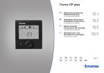
Bedienteil – CP classic
Combi
5
9
4
a
g, h
b
7
3
25
60°
40°
c
60°
f
d
e
3
1
1
a = Drehknopf für Raumtemperatur (1 – 5)
b = grüne LED leuchtet „Betrieb“
c = Warmwasserbetrieb
(Wassertemperatur 40 °C oder 60 °C)
d = Heiz- und Warmwasserbetrieb
(Heizen ohne kontrollierte Wassertemperatur
oder mit entleerter Wasseranlage)
Energiewahlschalter – CP E classic
Combi E
i
o
230 V~
j
k
l
m
n
i = Drehschalter für Energiewahl
j = Elektrobetrieb 230 V, 1800 W
k = Elektrobetrieb 230 V, 900 W
l = Gas- bzw. Dieselbetrieb
m = Mischbetrieb* (Gas- bzw. Diesel - und Elektrobetrieb 900 W)
n = Mischbetrieb* (Gas- bzw. Diesel - und Elektrobetrieb 1800 W)
o = gelbe LED leuchtet „Elektrobetrieb“
* Warmwasserbetrieb:
Im Warmwasserbetrieb wählt die Heizung automatisch den
Elektrobetrieb mit der vorgewählten elektrischen Leistung
von 900 W oder 1800 W.
Heizbetrieb:
Im Heizbetrieb hat der Elektrobetrieb vorrang. Reicht die
elektrische Heizleistung nicht aus, wird der Gas- bzw. Dieselbetrieb zugeschaltet.
Die maximale Heizleistung erhöht sich nicht durch
Zuschalten der elektrischen Heizstäbe.
3
Inbetriebnahme
Der Heizbetrieb ist je nach Betriebsstellung sowohl
mit als auch ohne Wasserinhalt möglich.
Warmwasserbetrieb
Diese Betriebsstellung ist nur mit gefülltem Boiler
zulässig.
Heiz- und Warmwasserbetrieb
Bei Geräten mit elektrischen Heizstäben
Mit dem Energiewahlschalter Gas- bzw. Diesel-,
Elektrobetrieb oder Mischbetrieb einstellen. Leuchtet die
gelbe LED (o) am Energiewahlschalter signalisiert dies den
Betrieb mit 230 V.
– Heizen mit kontrollierter Wassertemperatur
Am Bedienteil den Drehschalter auf Betriebsstellung (e) stellen.
Bei Geräten mit elektrischen Heizstäben
Mit dem Energiewahlschalter Gas- bzw. Diesel- oder Elektrobetrieb einstellen. Leuchtet die gelbe LED (o) am Energiewahlschalter signalisiert dies den Betrieb mit 230 V.
Im Warmwasserbetrieb ist ein Mischbetrieb – Gas bzw.
Diesel- und Elektrobetrieb – nicht möglich. Bei dieser
Einstellung wählt das Gerät automatisch den Elektrobetrieb
mit der vorgewählten Leistungsstufe von 900 W oder
1800 W.
Drehschalter am Bedienteil auf Stellung (c – Warmwasserbetrieb)
40 °C oder 60 °C stellen. Die grüne (b) und gelbe (g) LED
leuchten.
Nach Erreichen der eingestellten Wassertemperatur (40 °C
oder 60 °C) schaltet die Heizung ab und die gelbe LED (g)
erlischt.
Drehknopf (a) auf die gewünschte Thermostatstellung (1 – 5)
drehen. Die grüne LED (b) für Betrieb leuchtet und zeigt
gleichzeitig die Stellung der gewählten Raumtemperatur. Die
gelbe LED (g) zeigt die Aufheizphase des Wassers an.
Das Gerät wählt automatisch die benötigte Leistungsstufe,
entsprechend der Temperaturdifferenz zwischen der am
Bedienteil eingestellten und der gegenwärtigen Raumtemperatur. Nach Erreichen der am Bedienteil eingestellten
Raumtemperatur schaltet die Heizung zurück auf die kleinste
Stufe und heizt den Wasserinhalt auf 60 °C. Nach Erreichen
der Wassertemperatur schaltet die Heizung ab und die gelbe
LED (g) erlischt.
– Heizen ohne kontrollierte Wassertemperatur
Am Bedienteil den Drehschalter auf Betriebsstellung (d) stellen.
Drehknopf (a) auf die gewünschte Thermostatstellung (1 – 5)
drehen. Die grüne LED (b) für Betrieb leuchtet und zeigt
gleichzeitig die Stellung der gewählten Raumtemperatur. Die
gelbe LED (g – Aufheizphase des Wassers) leuchtet nur bei
Wassertemperaturen unter 5 °C!
4
Das Gerät wählt automatisch die benötigte Leistungsstufe,
entsprechend der Temperaturdifferenz zwischen der am
Bedienteil eingestellten und der gegenwärtigen Raumtemperatur. Nach Erreichen der am Bedienteil eingestellten Raumtemperatur schaltet die Heizung ab. Das Warmluftgebläse
läuft mit niedriger Drehzahl weiter, solange die Ausblastemperatur (am Gerät) höher als 40 °C ist.
Bei gefülltem Boiler wird das Wasser automatisch mitgeheizt.
Die Wassertemperatur ist dann abhängig von der abgegebenen Heizleistung und der Heizdauer für das Erreichen der
Raumtemperatur.
Ausschalten
Heizung am Bedienteil mit Drehschalter ausschalten (Stellung f).
Die grüne LED (b) erlischt.
Wasserinhalt bei Frostgefahr unbedingt entleeren!
Bei Geräten mit Gasbetrieb
Wenn das Gerät längere Zeit nicht benutzt wird, Schnellschlussventil in der Gaszuleitung und Gasflasche schließen.
Störung
– Heizen mit entleerter Wasseranlage
Am Bedienteil den Drehschalter auf Betriebsstellung (d) stellen.
Gas- bzw. Dieselbetrieb
Drehknopf (a) auf die gewünschte Thermostatstellung (1 – 5)
drehen. Die grüne LED (b) für Betrieb leuchtet und zeigt
gleichzeitig die Stellung der gewählten Raumtemperatur. Die
gelbe LED (g) leuchtet nur bei Gerätetemperaturen unter 5 °C!
Bei einer Störung blinkt auf dem Bedienteil die rote LED (h)
oder die gelbe LED (g).
Je nach Betriebsart wählt das Gerät automatisch die benötigte Leistungsstufe, entsprechend der Temperaturdifferenz
zwischen der am Bedienteil eingestellten und der gegenwärtigen Raumtemperatur. Nach Erreichen der am Bedienteil
eingestellten Raumtemperatur schaltet die Heizung ab. Das
Warmluftgebläse läuft mit niedriger Drehzahl weiter, solange
die Ausblastemperatur (am Gerät) höher als 40 °C ist.
Ein Rücksetzen (Störungsreset) erfolgt durch Ausschalten
– wenn am Bedienteil keine LED mehr blinkt – und erneutes
Einschalten der Heizung.
Mögliche Ursachen entnehmen Sie bitte der Fehlersuchanleitung.
Wird das Fenster geöffnet, an dem ein Fensterschalter
montiert ist, so unterbricht das Heizgerät den Betrieb
und die gelbe LED (g) blinkt 3 x. Nach Schließen des Fensters
setzt das Heizgerät den Betrieb fort.
5
Elektrobetrieb
Auf dem Energiewahlschalter erlischt die gelbe LED (o) und
am Bedienteil blinkt die gelbe LED (g) oder die rote LED (h).
Zubehör
Als Zubehör sind Abdeckrahmen in den Farben achatgrau,
schwarz, beige, platin oder gold erhältlich.
Mögliche Ursachen entnehmen Sie bitte der Fehlersuchanleitung.
Wird während des Betriebes die Spannungsversorgung
230 V nur kurzzeitig (ca. 1 Sekunde) unterbrochen, läuft
die Heizung anschließend im Elektrobetrieb weiter.
Mischbetrieb
Störung in der Spannungsversorgung 230 V
Auf dem Energiewahlschalter erlischt die gelbe LED (o) und
die gelbe LED (g) am Bedienteil blinkt 2 x.
Passend für die Bedienelemente geben die in 8 verschiedenen
Farben erhältlichen Seitenteile einen optisch gefälligen Abschluss. Bitte wenden Sie sich hierzu an Ihren Fachhändler.
Mögliche Ursachen entnehmen Sie bitte der Fehlersuchanleitung.
Anreihclip, 1 Stück (Art.-Nr. 34000-65900). Für die Montage
mehrerer Truma Bedienelemente nebeneinander.
Wird während des Mischbetriebes die Spannungsversorgung
230 V unterbrochen, schaltet die Heizung automatisch in den
Gasbetrieb. Sobald die Spannungsversorgung 230 V wieder
hergestellt ist, schaltet die Heizung automatisch in den Mischbetrieb zurück.
Störung im Verbrennungsvorgang
Auf dem Energiewahlschalter leuchtet die gelbe LED (o) und
die rote LED (h) oder die gelbe LED (g) am Bedienteil blinkt.
Mögliche Ursachen entnehmen Sie bitte der Fehlersuchanleitung.
Erlischt während des Mischbetriebes die Flamme (z. B. leere
Gasflasche oder verschlossener Abgasaustritt), schaltet die
Heizung automatisch in den Elektrobetrieb. Soll die Heizung
wieder im Mischbetrieb laufen, muss die Ursache der Störung
beseitigt und am Bedienteil aus- und wieder eingeschaltet
werden (Störungsreset).
6
Weiteres Zubehör (ohne Abbildung) für das Bedienteil:
– Bedienteilkabel 3 m (Art.-Nr. 36110-01)
– Bedienteilkabel 6 m (Art.-Nr. 36110-02)
– Bedienteilkabel 9 m (Art.-Nr. 36110-03)
Fehlersuchanleitung (Heizung Combi Gas)
Blinkcode am analogen Bedienteil – CP classic
Blinkfolge LED:
– An / Aus:
0,5 Sekunden
Pause zwischen Blinkfolge: 5 Sekunden
Fehler
Ursache
Behebung
Es leuchtet keine LED, das Gerät
– Automatischer Wiederanlauf ist – Rücksetzen (Störungsreset) durch Ausschalten,
ist eingeschaltet und Betriebsspanblockiert, z. B. nach einer Unter5 Sekunden Warten und erneutes Einschalten
nung liegt an
brechung der Stromversorgung.
– Batteriespannung 12 V prüfen, gegebenenfalls Batterie laden
– Alle elektrischen Steckverbindungen prüfen
– Geräte- oder Fahrzeugsicherung – Geräte- oder Fahrzeugsicherung prüfen gegebenenfalls erneuern
(siehe Sicherungen)
defekt
Nach dem Einschalten
leuchtet keine LED
– Keine Betriebsspannung
Nach dem Einschalten
leuchtet die grüne LED, aber
die Heizung läuft nicht
– Die eingestellte Temperatur auf
dem Bedienteil ist niedriger als
die Raumtemperatur
– Raumtemperatur am Bedienteil höher einstellen
gelbe LED blinkt 1 x
(Heizung weiter in Betrieb)
– Drohende Unterspannung
Batteriespannung zu niedrig
< 10,4 V
– Batterie laden
gelbe LED blinkt 2 x
(Heizung nicht in Funktion)
– Unterspannung
Batteriespannung zu niedrig
< 10,0 V
– Batterie laden. Gegebenenfalls überalterte Batterie ersetzen
– Überspannung > 16,4 V
– Batteriespannung und Spannungsquellen wie z. B. das Ladegerät prüfen
– Keine 230 V Betriebsspannung
– Sicherung 230 V defekt
– Überhitzungsschutz hat
ausgelöst
– Betriebsspannung 230 V wieder herstellen
– Sicherung 230 V erneuern
– Überhitzungsschutz rücksetzen, Heizung abkühlen lassen,
Anschlussabdeckung abnehmen und Resetknopf drücken
Nach dem Einschalten der Heizung
leuchtet die grüne LED und die
(Nur bei Combi E)
gelbe LED blinkt 3 x
– Fenster über dem Kamin
offen (Fensterschalter)
– Das Fenster schließen
7
Fehler
Ursache
gelbe LED blinkt 4 x
– Sommerbetrieb mit leerem
(Heizung schaltet sich nach einer
Wasserbehälter
längeren Betriebsdauer auf Störung)
gelbe LED blinkt 5 x
Behebung
– Gerät ausschalten und abkühlen lassen,
Boiler mit Wasser füllen
– Warmluftaustritte blockiert
– Kontrolle der einzelnen Austrittsöffnungen
– Umluftansaugung blockiert
– Blockade der Umluftansaugung entfernen
– Raumtemperaturfühler oder
-kabel defekt
– Wenden Sie sich bitte an den Truma Service
gelbe LED blinkt 7 x
– Bedienteil oder -kabel defekt
– Wenden Sie sich bitte an den Truma Service
gelbe LED blinkt 8 x
– Heizelement für FrostControl
hat einen Kurzschluss
– Stecker des Heizelements an der elektronischen Steuereinheit abziehen, Heizelement austauschen
gelbe LED blinkt 9 x
(ca. 30 Sekunden nach dem Einschalten der Heizung)
– Gasflasche oder Schnellschluss- – Gaszufuhr prüfen und Ventile offnen
ventil in der Gaszuleitung
geschlossen
– Gasflasche leer
(Heizung schaltet sich nach einer
– Gasdruck-Regelanlage vereist
längeren Betriebsdauer auf Störung)
– Butananteil in der Gasflasche
zu hoch
Die rote LED blinkt 1 x - 8 x
– Störung in der Heizung
– Gasflasche wechseln
– Reglerbeheizung (EisEx) verwenden
– Propan verwenden (insbesondere bei Temperaturen unter 10 °C ist
Butan zum Heizen ungeeignet)
– Wenden Sie sich bitte an den Truma Service.
Eventuell Blinkcode (kurz, lang) ermitteln: Rote LED auf
Heizungselektronik.
Grüne LED blinkt (5 Hz) nach dem – Nachlauf zur TemperaturreduAusschalten der Heizung
zierung des Geräts ist aktiv
– Kein Fehler. Nachlauf schaltet sich nach max. 5 Minuten ab
Raumheizung reagiert nach dem
Einstellen nicht sofort
– Nachlauf zur Temperaturreduzierung des Geräts ist aktiv
– Kein Fehler. Nachlauf schaltet sich nach max. 5 Minuten ab
Nach dem Einschalten leuchtet
die grüne und die rote LED
– Elektronik ist defekt
– Wenden Sie sich bitte an den Truma Service
Sollten diese Maßnahmen nicht zur Störungsbehebung führen, wenden Sie sich bitte an den Truma Service.
8
Fehlersuchanleitung (Heizung Combi Diesel)
Blinkcode am analogen Bedienteil – CP classic
Blinkfolge LED:
– An / Aus:
0,5 Sekunden
Pause zwischen Blinkfolge: 5 Sekunden
Fehler
Ursache
Behebung
Nach dem Einschalten
leuchtet keine LED
– Keine Betriebsspannung
– Batteriespannung 12 V prüfen, ggf. Batterie laden
– Geräte- oder Fahrzeugsicherung – Alle elektrischen Steckverbindungen prüfen
defekt
– Geräte- oder Fahrzeugsicherung prüfen,
gegebenenfalls erneuern (siehe Sicherungen)
Nach dem Einschalten
leuchtet die grüne LED,
aber die Heizung läuft nicht
– Die eingestellte Temperatur auf
dem Bedienteil ist niedriger als
die Raumtemperatur
– Raumtemperatur am Bedienteil höher einstellen
Grüne LED blinkt (5 Hz) nach
dem Ausschalten der Heizung
– Nachlauf zur Temperaturreduzierung des Geräts ist aktiv
– Kein Fehler, Nachlauf schaltet sich nach max. 5 Minuten ab
Rote LED blinkt 6 x
– Kraftstoffmangel durch geringe
Tankfüllung, leergefahreren
Tank und/oder Schräglage des
Fahrzeuges
– Tank mit Kraftstoff befüllen, anschließend die Kraftstoffleitung wie
unter „Erstinbetriebnahme“ befüllen
Rote LED blinkt (außer 6 x)
oder rote LED leuchtet
– Störung Heizgerät
– Wenden Sie sich bitte an den Truma Service
Gelbe LED blinkt 1 x
– Drohende Unterspannung
< 11,5 V
– Sparsam mit der elektrischen Energie aus der Batterie
umgehen, z. B. Beleuchtung einschränken
– Batterie laden
Gelbe LED blinkt 2 x
– Unterspannung < 10,2 V
– Batteriespannung prüfen, ggf. Batterie laden
– Kurzfristige Sofortmaßnahme, starke Verbraucher abschalten,
bzw. Fahrzeugmotor starten bis die Heizung läuft
(ca. 4 Minuten)
– Batteriekapazität unzureichend, ggf. überalterte Batterie
austauschen
9
Fehler
Ursache
Behebung
Gelbe LED blinkt 2 x
– Überspannung > 16,4 V
– Batteriespannung und Spannungsquellen wie z. B. das
Ladegerät prüfen
(Nur bei Combi E)
– Keine 230 V Betriebsspannung
– Sicherung 230 V defekt
– Überhitzungsschutz hat
ausgelöst
Gelbe LED blinkt 3 x
– Fenster über dem Kamin
offen (Fensterschalter)
Gelbe LED blinkt 4 x
– Warmlufttemperatur
bzw. Wassertemperatur
überschritten:
– Betriebsspannung 230 V wieder herstellen
– Sicherung 230 V erneuern
– Überhitzungsschutz rücksetzen, Heizung abkühlen lassen,
Anschlussabdeckung abnehmen und Resetknopf drücken
– Fenster schließen
– Nicht alle Warmluftrohre sind
angeschlossen
– Warmluftaustritte blockiert
– Umluftansaugung blockiert
– Kontrolle, ob 4 Warmluftrohre angeschlossen sind
– Sommerbetrieb mit leerem
Wasserbehälter
– Boiler mit Wasser füllen
Gelbe LED blinkt 5 x
– Raumtemperaturfühler oder
Kabel defekt
– Wenden Sie sich bitte an den Truma Service
Gelbe LED blinkt 6 x
– Wassertemperatur im
Sommerbetrieb überschritten
– Bedienteil oder Bedienteilkabel
defekt
– Heizelement für FrostControl
hat einen Kurzschluss
– Boiler mit Wasser füllen
Gelbe LED blinkt 7 x
Gelbe LED blinkt 8 x
– Kontrolle der einzelnen Austrittsöffnungen
– Blockade der Umluftansaugung entfernen
– Wenden Sie sich bitte an den Truma Service
– Stecker des Heizelements an der elektronischen Steuereinheit
abziehen, Heizelement austauschen
Sollten diese Maßnahmen nicht zur Störungsbehebung führen, wenden Sie sich bitte an den Truma Service.
10
Technische Daten
Abmessungen (LxBxH)
Einbauanweisung
53 x 53 x 44 mm
Sicherheitshinweise
Technische Änderungen vorbehalten!
Wartung
Der Einbau in Fahrzeuge muss den technischen und administrativen Bestimmungen
des jeweiligen Verwendungslandes entsprechen (z. B. EN 1648, VDE 0100-721).
Nationale Vorschriften und Regelungen
müssen beachtet werden.
Die Bedienelemente sind wartungsfrei.
Entsorgung
Das Gerät ist gemäß den administrativen Bestimmungen
des jeweiligen Verwendungslandes zu entsorgen. Nationale
Vorschriften und Gesetze (in Deutschland ist dies z. B. die
Altfahrzeug-Verordnung) müssen beachtet werden.
Konformitätserklärung
Die Bedienelemente sind berechtigt, das CE-Zeichen zu führen.
(Konformitätserklärung – siehe Gebrauchsanweisung der entsprechenden Heizung)
Die CE-Produkt-Ident-Nummer der Heizung bleibt unverändert
gültig.
ESD-Vorschriften beachten!
Lieferumfang
CP classic (für Geräte ohne elektrische Heizstäbe)
1 Bedienteil CP classic
1 Gebrauchs- und Einbauanweisung
CP E classic (für Geräte mit elektrischen Heizstäben)
1 Bedienteil CP classic
1 Energiewahlschalter CP E classic
1 Bedienteil-Verbindungskabel
1 Gebrauchs- und Einbauanweisung
Separat zu bestellen
– Anschlusskabel (zur Verbindung des Bedienteils / Energiewahlschalters mit der Heizung – in verschiedenen Längen
erhältlich.)
– Abdeckrahmen, Seitenteile und ggf. Anreihclip
11
Montage
Bedienteil CP classic und
Energiewahlschalter CP E classic
Platzwahl
Bedienelemente an einer vor Feuchtigkeit und Nässe geschützten Stelle einbauen.
Bedienteil CP classic
– Loch Ø 55 mm bohren.
– Achtung: Länge des Anschlusskabels max. 10 m.
– Stecker (3) des Anschlusskabels (2) am Bedienteil (1)
anstecken.
– Das Anschlusskabel (2) in die Kabelführung des Bedienteils
klemmen.
– Das Anschlusskabel (2) zur Heizung verlegen und
anstecken.
– Darauf achten, dass alle Stecker eingerastet sind.
– Bedienteil mit 4 Schrauben (4) befestigen.
– Abdeckrahmen (10) mit Seitenteilen (11) aufstecken.
– Jeweils ein Loch Ø 55 mm bohren (Abstand Lochmitte 66 mm).
– Bedienteil (1) und Energiewahlschalter (5) mit BedienteilVerbindungskabel (6) verbinden.
– Achtung: Länge des Anschlusskabels max. 10 m.
– Stecker (3) des Anschlusskabels (2) am Energiewahlschalter (5) anstecken. Die Kabel (2 + 6) in die Kabelführungen
der Bedienelemente klemmen.
– Das Anschlusskabel (2) zur Heizung verlegen und
anstecken.
– Darauf achten, dass alle Stecker eingerastet sind.
– Bedienelemente jeweils mit 4 Schrauben (4) befestigen
– Abdeckrahmen (10) mit Seitenteilen (11) aufstecken.
m
m
m
m
66
55
Ø
6
m
Ø
55
m
1
2
4
2
4
i
mb
Co 60°
3
°
3
4
3
1
3
5
3
2
40
1
11
11
12
10
5
11
4
10
11
10
Control panels CP (E) classic
Symbols used
Table of Contents
Symbols used ...................................................................... 14
Intended use ..................................................................... 14
The unit must only be installed and repaired by an
expert.
Operating instructions
Note containing information and tips.
Safety instructions ...........................................................
Display and control panels .............................................
Control panel – CP classic ...................................................
Power selector switch – CP E classic ..................................
Start-up ..............................................................................
Hot water mode ..................................................................
Heating and hot water mode ..............................................
Switching off ....................................................................
Fault ....................................................................................
Gas or diesel mode ..............................................................
Electrical mode ....................................................................
Mixed mode ........................................................................
Accessories .......................................................................
Troubleshooting guide (Combi Gas heating system) .
Troubleshooting guide (Combi Diesel heating system) .
Technical data ...................................................................
Maintenance .....................................................................
Disposal .............................................................................
Declaration of conformity ...............................................
15
15
15
15
16
16
16
17
17
17
18
18
18
19
21
23
23
23
23
Please pay attention to the ESD regulations!
Electrostatic charge can destroy the electronics.
Ensure that potential compensation is present before touching the electronics.
Intended use
Control panel – CP classic
The room temperature and the water temperature can be set
at a Truma Combi (E) heating system using the control panel.
Power selector switch – CP E classic
It is possible to choose between gas, diesel and/or electrical
energy at a Truma Combi (E) heating system (with heating
elements for electrical mode) using the power selector switch.
The CP classic control panel is also required.
The control panels are intended for installation in caravans
and motor homes. Installation in boats is not permitted.
Installation instructions
Safety instructions ........................................................... 23
Scope of delivery .............................................................. 23
Assembly ........................................................................... 24
13
e = Heating and hot water mode
(heating with water temperature monitoring)
f = Rotary switch “Off”
g = Yellow LED lit, “Boiler heat-up phase”
yellow LED flashing “Warning”
r = Red LED lit, red LED flashing “Fault”
Operating instructions
Safety instructions
– The heating system or control panel must not be used unless it is in perfect working order.
– Repairs must be carried out immediately. Only carry out
repairs yourself if the solution is described in the troubleshooting guide of this manual.
– Do not make repairs or modifications to the heating system
or the control panel!
– A defective heating system or defective control panel may only be repaired by the manufacturer or his service department.
Control panel – CP classic
Combi
7
3
5
2
5
9
4
a
g, h
b
40°
c
60°
f
d
e
3
1
1
a = Control knob for room temperature (1 – 5)
b = Green LED lit, “On”
c = Hot water mode
(Water temperature 40 °C or 60 °C)
d = Heating and hot water mode
(heating without water temperature monitoring or with
drained water system)
14
Combi E
i
o
230 V~
Display and control panels
60°
Power selector switch – CP E classic
j
k
l
m
n
i = Power selection rotary switch
j = Electrical mode 230 V, 1800 W
k = Electrical mode 230 V, 900 W
l = Gas or diesel mode
m = Mixed mode* (gas, diesel or electrical mode 900 W)
n = Mixed mode* (gas, diesel or electrical mode 1800 W)
o = Yellow LED lit = “Electrical mode”
* Hot water mode
In hot water mode the heating system automatically selects
electrical mode at the preselected electrical power setting of
900 W or 1800 W.
Heating mode:
Electrical mode has priority in heating mode. If the electrical
heating output is insufficient, gas or diesel mode is enabled.
Switching on the electric heating elements as well
does not increase the maximum heating power.
Start-up
Heating mode is possible with or without water
content depending on the operating mode.
Hot water mode
This operating mode can only be used if the boiler has
been filled.
Heating and hot water mode
Devices with electrical heating elements
Select gas, diesel, electrical or mixed mode using the power
selector switch. Illumination of the yellow LED (o) at the
power selector switch indicates that the unit is operating
with 230 V.
– Heating with water temperature monitoring
Move rotary switch on control panel to “On” position (e).
Devices with electrical heating elements
Select diesel or electrical mode using the power selector
switch. Illumination of the yellow LED (o) at the power selector switch indicates that the unit is operating with 230 V.
Mixed mode (gas or diesel and electrical mode) is not
possible in hot water mode. With this setting the unit
automatically selects electrical mode with a preselected
power setting of 900 W or 1800 W.
Move the rotary switch on the control panel to position
(c - hot water mode) 40 °C or 60 °C. The green (b) and
yellow (g) LEDs light up.
After reaching the set water temperature (40 °C or 60 °C), the
heating system will switch off and the yellow LED (g) will be
extinguished.
Set the rotary switch (a) to the desired thermostat setting
(1 – 5). The green LED (b) for operation is lit and simultaneously indicates the position of the selected room temperature. The
yellow LED (g) indicates the water‘s heat-up phase.
The unit automatically selects the required operating level
according to the temperature difference between the setting on the control panel and the current room temperature.
When the room temperature selected on the control panel is
reached, the heating system switches back to the smallest
setting and heats the water to 60 °C. Once the water temperature is reached, the heating system switches off and the
yellow LED (g) goes out.
– Heating without water temperature monitoring
Move rotary switch on control panel to “On” position (d).
Set the rotary switch (a) to the desired thermostat setting
(1 – 5). The green LED (b) for operation is lit and simultaneously indicates the position of the selected room temperature. The
yellow LED (g - water heat-up phase) will be lit only when the
water temperature is below 5 °C!
15
The unit automatically selects the required operating level
according to the temperature difference between the setting
on the control panel and the current room temperature. Once
the room temperature selected on the control panel has been
reached, the heating system switches off. The warm air fan
will continue to run at a low speed as long as the blow-out
temperature (on the unit) is higher than 40 °C.
If the boiler has been filled, the water is automatically heated as well. The water temperature is then dependent on the
heating output being given off, and the duration of heating
required to reach the desired room temperature.
– Heating with drained water system
Move rotary switch on control panel to "On" position (d).
Set the rotary switch (a) to the desired thermostat setting
(1 – 5). The green LED (b) for operation is lit and simultaneously indicates the position of the selected room temperature. The
yellow LED (g) will only be lit if the temperature of the unit is
below 5 °C!
Depending on the operating mode, the unit will automatically
select the required operating level according to the temperature difference between the setting on the control panel and
the current room temperature. Once the room temperature
selected on the control panel has been reached, the heating
system switches off. The warm air fan will continue to run at a
low speed as long as the blow-out temperature (on the unit) is
higher than 40 °C.
16
Switching off
Switch off heating system at control panel using rotary switch
(position f). The green LED (b) goes off.
Always drain water contents if there is a risk of frost!
Units with gas mode
If the unit is not going to be used for a long period of time,
close the quick-acting valve in the gas supply line and turn
off the gas cylinder.
Fault
Gas or diesel mode
In the event of a fault the red LED (h) or the yellow LED (g) on
the control panel will flash.
Possible causes can be found in the troubleshooting guide.
A reset (fault reset) is carried out by switching off, waiting
until all LED’s on the control panel have stopped flashing, and
then switching the heating system on again.
If the window to which a window switch is mounted is
opened, the heater stops operating and the yellow LED (g)
flashes 3 times. The heater continues operating when the window is closed.
Electrical mode
The yellow LED (o) goes off on the power selector switch,
and the yellow LED (g) or the red LED (h) flashes on the
control panel.
Accessories
Cover frames are available as accessories in the colours agate
grey, black, beige, platinum and gold.
Possible causes can be found in the troubleshooting guide.
If the 230 V power supply is interrupted for just a brief
period of approximately 1 second during operation, the
heating system will subsequently resume in electrical mode.
Mixed mode
Fault in the 230 V power supply
The yellow LED (o) on the power selector switch goes off and
the yellow LED (g) on the control panel flashes 2 x.
Possible causes can be found in the troubleshooting guide.
Matching side parts are available for the control panels in
8 different colours, and create a visually attractive finish.
Please contact your specialist dealer in this connection.
Line-up clip, 1 piece (part no. 34000-65900). For installing several Truma control panels next to each other.
If the 230 V power supply is interrupted during mixed mode,
the heating system will automatically switch to gas mode.
As soon as the 230 V power supply is restored, the heating
system automatically switches back to mixed mode.
Fault in the combustion procedure
The yellow LED (o) on the power selector switch illuminates
and the red LED (h) or the yellow LED (g) on the control panel
flashes.
Possible causes can be found in the troubleshooting guide.
Other accessories (without picture) for control panel:
If the flame goes out during mixed mode (e.g. empty gas cylinder or closed exhaust outlet), the heating system automatically
switches to electrical mode. For the heating system to operate
in mixed mode again, the cause of the fault must be remedied
and the control panel switched off and on again (fault reset).
– 3 m control panel cable (part no. 36110-01)
– 6 m control panel cable (part no. 36110-02)
– 9 m control panel cable (part no. 36110-03)
17
Troubleshooting guide (Combi Gas heating system)
Flashing code at analogue control panel – CP Classic
Flash sequence LED:
– On / Off:
0.5 seconds
Pause between flash sequence:
5 seconds
Fault
Cause
Rectification
No LED is on, the unit is switched
on and is supplied with operating
current
– Automatic restart is blocked, e.g. – Reset (fault reset) by switching off, waiting 5 seconds and then
after an power failure.
switching on again
No LED illuminates
after switching on.
– No operating voltage
– Device fuse or vehicle fuse
defective
The green LED comes on when the – The temperature setting on the
unit is switched on, but the heating control panel is lower than the
system does not operate
room temperature
– Check 12 V battery voltage, charge battery if necessary
– Check all electrical plug connections
– Check fuse of unit or vehicle and replace if necessary (see fuses)
– Select higher room temperature at the control panel
After switching on the heating system, the green LED illuminates and
the yellow LED flashes 1 x
– Risk of low voltage
(Heating system continues to operate) Battery voltage too low
< 10.4 V
yellow LED flashes 2 x
– Low voltage
(Heating system not operating)
Battery voltage too low
< 10.0 V
– Overvoltage > 16.4 V
– Charge battery
(Only with Combi E)
– Restore 230 V operating voltage
– Replace 230 V fuse
– Reset overheating protection, allow heating system to cool,
remove connection cover and press reset button
– Close window
yellow LED flashes 3 x
18
– No 230 V operating voltage
– 230 V fuse defective
– Overheating protection has been
triggered
– Open window above cowl
(window switch)
– Charge battery. If necessary replace old battery
– Check battery voltage and voltage sources such as the charger
Fault
Cause
Rectification
yellow LED flashes 4 x
(After operating for a longer period of time, the heating system
switches to failure)
– Summer mode with empty
water container
– Switch unit off and allow to cool,
fill boiler with water
yellow LED flashes 5 x
yellow LED flashes 7 x
yellow LED flashes 8 x
yellow LED flashes 9 x
(approx. 30 seconds after switching on the heating system)
– Warm air outlets blocked
– Check individual outlet apertures
– Circulated air intake blocked
– Remove blockage from circulated air intake
– Room temperature sensor or
cable defective
– Control panel or control panel
cable defective
– FrostControl heating element
has a short circuit
– Gas cylinder or quick-acting
valve in gas supply line closed
– Please contact Truma Service
– Gas cylinder empty
(After operating for a longer period of time, the heating system
switches to failure)
Red LED flashes 1 - 8 times
Green LED flashes (with 5 Hz)
after the heating system has been
switched off
Room heating does not react to
adjustment immediately
After switching on the green and
the red LED illuminate
– Please contact Truma Service
– Disconnect heating element plug from electronic control unit, replace heating element
– Check gas supply and open valves
– Replacing a gas cylinder
– Gas pressure regulation system – Use regulator heater (EisEx)
iced up
– Butane content in the gas cylin- – Use propane (butane is unsuitable for heating, particularly at temder too high
peratures below 10 °C)
– Heating system fault
– Please contact Truma Service.
Determine flashing code (short, long) if necessary: Red LED on
heater electronics.
– After-running is active to reduce – No fault. After-run switches itself off after max. 5 minutes.
the temperature of the unit
– After-running is active to reduce – No fault. After-run switches itself off after max. 5 minutes
the temperature of the unit
– Faulty electronics
– Please contact Truma Service
If these actions do not remedy the problem, please contact Truma Service.
19
Troubleshooting guide (Combi Diesel heating system)
Flashing code in analogue control panel – CP Classic
Flash sequence LED:
– On / Off:
0.5 seconds
Pause between flash sequence: 5 seconds
Fault
Cause
Rectification
No LED illuminates
after switching on.
– No operating voltage
– Device fuse or vehicle fuse
defective
– Check 12 V battery voltage, charge battery if necessary
– Check all electrical plug connections
– Check fuse of unit or vehicle, replace if necessary (see fuses)
The green LED illuminates when
the unit is switched on, but the
heating system does not operate
– The temperature setting on the
control panel is lower than the
room temperature
– Select higher room temperature at the control panel
Green LED flashes (with 5 Hz)
after the heating system has been
switched off
– After-running is active to reduce – No fault, after-run switches itself off after max. 5 minutes
the temperature of the unit
Red LED flashes 6 x
– Lack of fuel due to insufficient
fuel tank filling, tank has run
empty and / or vehicle is on a
slope
– Fill tank with fuel, then fill fuel line as described in "Initial start-up"
Red LED flashes (except 6 times)
or red LED permanently on
– Heater malfunction
– Please contact Truma Service
Yellow LED flashes 1 x
– Risk of low voltage
< 11.5 V
– Use the electrical power from the battery sparingly,
e.g. restrict lighting
– Charge battery
Yellow LED flashes 2 x
– Undervoltage < 10.2 V
– Check battery voltage, charge battery if necessary
– Short-term immediate action, switch off major consumers
or start up vehicle engine until the heating system starts running
(approx. 4 minutes)
– Battery capacity inadequate, if necessary exchange old battery
20
Fault
Cause
Rectification
Yellow LED flashes 2 x
– Overvoltage > 16.4 V
(Only with Combi E)
– Restore 230 V operating voltage
– No 230 V operating voltage
– Replace 230 V fuse
– 230 V fuse defective
– Overheating protection has been – Reset overheating protection, allow heating system to cool,
remove connection cover and press reset button
triggered
Yellow LED flashes 3 x
– Open window above cowl
(window switch)
Yellow LED flashes 4 x
– Warm air temperature and / or
water temperature exceeded:
– Check battery voltage and voltage sources such as the
charger
– Close window
– Not all warm air ducts are
connected
– Warm air outlets blocked
– Circulated air intake blocked
– Check whether the 4 warm air ducts are connected
– Summer mode with empty
water container
– Fill boiler with water
Yellow LED flashes 5 x
– Room temperature sensor or
cable defective
– Please contact Truma Service
Yellow LED flashes 6 x
– Water temperature exceeded in
summer mode
– Control panel or control panel
cable defective
– FrostControl heating element
has a short circuit
– Fill boiler with water
Yellow LED flashes 7 x
Yellow LED flashes 8 x
– Check individual outlet apertures
– Remove blockage from circulated air intake
– Please contact Truma Service
– Disconnect heating element plug from electronic control unit,
replace heating element
If these actions do not remedy the problem, please contact Truma Service.
21
Technical data
Dimensions (LxWxH)
Installation instructions
53 x 53 x 44 mm
Safety instructions
Right reserved to make technical changes!
Maintenance
In-vehicle installations must comply with
the technical and administrative regulations of the respective country of use (e.g.
EN 1648, VDE 0100-721). National regulations and rules must be followed.
The control panels are maintenance free.
Disposal
The unit must be disposed of in line with the administrative
regulations of the respective country in which it is used.
National regulations and laws (in Germany, for example, the
End-of-life Vehicle Regulation) must be observed.
Declaration of conformity
The control panels are entitled to bear the CE symbol. (Conformity declaration – see operating instructions of relevant
heating system)
The CE product identification number of the heating system
remains valid.
22
Please pay attention to the ESD regulations!
Scope of delivery
CP classic (for units without electrical heating elements)
1 CP classic control panel
1 Set of operating and installation instructions
CP E classic (for units with electrical heating elements)
1 CP classic control panel
1 Power selector switch – CP E classic
1 Control panel connecting cable
1 Set of operating and installation instructions
To be ordered separately
– Connector cables (for connecting control panel / power
selector switch to heating system - available in different
lengths)
– Cover frame, side parts and line-up clip if necessary
Assembly
CP classic control panel and
CP E classic power selector switch
Selecting a location
Install control panels in a location that is protected from moisture and humidity.
CP classic control panel
Drill hole with diameter of 55 mm.
Attention: Maximum length of connector cable 10 m.
Attach plug (3) of the connector cable (2) to control panel (1).
Clamp connector cable (2) in cable duct of control panel.
Route connector cable (2) to heating system and plug in.
Ensure that all connectors are engaged.
Secure control panel with 4 screws (4).
Fit cover frame (10) with side parts (11).
m
Ø
55
m
m
m
m
66
55
Ø
6
m
2
1
4
2
4
i
mb
Co 60°
°
4
3
1
5
3
2
40
3
–
–
–
–
–
–
–
–
– Drill hole with a diameter of 55 mm for each device
(distance between hole centres 66 mm).
– Connect control panel (1) and power selector switch (5)
using control panel connecting cable (6).
– Attention: Maximum length of connector cable 10 m.
– Attach plug (3) of connector cable (2) to power selector
switch (5). Clamp cables (2 + 6) into control panel cable
guides.
– Route connector cable (2) to heating system and plug in.
– Ensure that all connectors are engaged.
– Secure each control panel with 4 screws (4).
– Fit cover frame (10) with side parts (11).
3
1
11
11
3
5
11
4
10
10
11
10
23
Éléments de commande CP (E) classic
Table des matières
Volume de livraison ......................................................... 35
Montage ............................................................................. 36
Symboles utilisés ................................................................. 26
Utilisation .......................................................................... 26
Symboles utilisés
Mode d'emploi
Informations concernant la sécurité .............................
Éléments d'affichage et de commande ........................
Pièce de commande – CP classic ........................................
Commutateur d'énergie – CP E classic ...............................
Mise en service .................................................................
Mode chauffe-eau ...............................................................
Mode chauffage et chauffe-eau ..........................................
Arrêt ....................................................................................
Panne ..................................................................................
Mode gaz ou diesel .............................................................
Mode électricité ...................................................................
Mode mixte .........................................................................
Accessoires .......................................................................
Instructions de recherche de pannes
(chauffage Combi Gas) ....................................................
Instructions de recherche de pannes
(chauffage Combi Diesel) ................................................
Caractéristiques techniques ...........................................
Maintenance .....................................................................
Mise au rebut ....................................................................
Déclaration de conformité ..............................................
27
27
27
27
28
28
28
29
29
29
29
30
30
31
33
35
35
35
35
Instructions de montage
Informations concernant la sécurité ............................. 35
24
Le montage et la réparation de l'appareil doivent
être effectués uniquement par un spécialiste.
Remarque avec informations et conseils.
Respecter les prescriptions ESD. Une charge électrostatique peut provoquer la destruction de l'électronique. Avant
de toucher l'électronique, établir la compensation de potentiel.
Utilisation
Pièce de commande – CP classic
La pièce de commande permet de régler la température
ambiante et de l'eau sur un chauffage Truma Combi (E).
Commutateur d'énergie – CP E classic
Avec le commutateur d'énergie, il est possible sur un chauffage Truma Combi E (avec thermoplongeurs pour le mode
électricité) de choisir entre les types d'énergie gaz ou diesel
et/ou l'énergie électrique. La pièce de commande CP classic
est également nécessaire.
Les éléments de commande sont destinés au montage dans
les caravanes et les camping-cars. Le montage dans les bateaux est interdit.
Mode d'emploi
Informations concernant la sécurité
– Exploiter le chauffage ou un élément de commande seulement dans un état techniquement irréprochable.
– Faire supprimer immédiatement les pannes. Supprimer les
pannes soi-même seulement si l'opération de dépannage
est décrite dans les instructions de recherche de pannes de
ce mode d'emploi.
– Ne pas procéder à aucun travail de réparation ou modification sur le chauffage ou l'élément de commande.
– Faire réparer un chauffage ou un élément de commande
défectueux seulement par le fabricant ou son SAV.
Éléments d'affichage et de commande
Pièce de commande – CP classic
Combi
7
3
25
60°
5
9
4
a
g, h
b
40°
c
60°
f
d
e
3
1
1
a = Bouton de réglage pour le réglage de la température
ambiante (1 – 5)
b = LED verte allumée « Fonctionnement »
c = Mode chauffe-eau (température de l'eau 40 °C ou 60 °C)
d = Mode chauffage et chauffe-eau (chauffage sans contrôle
de la température d'eau ou avec installation d'eau purgée)
e = Mode chauffage et chauffe-eau
(chauffage avec température contrôlée de l'eau)
f = Commutateur rotatif « Arrêt »
g = LED jaune allumée « Phase de mise en température du
chauffe-eau » la LED jaune clignote « Avertissement »
h = LED rouge allumée, LED rouge clignote « Panne »
Commutateur d'énergie – CP E classic
Combi E
i
o
230 V~
j
k
l
m
n
i = Commutateur rotatif pour le choix de l'énergie
j = Mode électricité 230 V, 1 800 W
k = Mode électricité 230 V, 900 W
l = Mode gaz ou diesel
m = Mode mixte * (mode gaz ou diesel et mode électricité
900 W)
m = Mode mixte * (mode gaz ou diesel et mode électricité
1 800 W)
o = LED jaune allumée : « Mode électricité »
* Mode chauffe-eau :
En mode chauffe-eau, le chauffage sélectionne automatiquement le mode électricité avec la puissance électrique
présélectionnée de 900 W ou 1 800 W.
Mode chauffage :
Le mode électricité est ici prioritaire. Si la puissance de chauffe
électrique ne suffit pas, le mode gaz ou diesel s'active.
La mise en circuit des thermoplongeurs électriques
n'augmente pas la puissance de chauffe maximale.
25
Mise en service
– Chauffage avec température contrôlée de l'eau
Selon la position de fonctionnement, le mode
chauffage est possible aussi bien avec que sans le
volume d'eau.
Sur la pièce de commande, régler le commutateur rotatif sur
la position de fonctionnement (e).
Mode chauffe-eau
Cette position de fonctionnement est autorisée seulement avec le chauffe-eau rempli.
Appareils avec thermoplongeurs électriques
Régler le mode gaz, diesel ou électricité à l'aide du commutateur d'énergie. La LED jaune (o) allumée sur le commutateur d'énergie indique le fonctionnement en 230 V.
En mode chauffe-eau, un mode mixte – gaz ou diesel
et électricité – n'est pas possible. Dans ce réglage,
l'appareil sélectionne automatiquement le mode électricité
avec le palier de puissance présélectionné de 900 W ou
1 800 W.
Régler le commutateur rotatif sur la pièce de commande en position (c – mode chauffe-eau) 40 °C ou 60 °C. La LED verte (b)
et la LED jaune (g) s'allument.
Une fois atteinte la température d'eau réglée (40 °C ou 60 °C),
le chauffage s'arrête et la LED jaune (g) s'éteint.
Mode chauffage et chauffe-eau
Appareils avec thermoplongeurs électriques
Régler le mode gaz, diesel, électricité ou mixte à l'aide du
commutateur d'énergie. La LED jaune (o) allumée sur le
commutateur d'énergie indique le fonctionnement en 230 V.
26
Tourner le bouton de réglage (a) sur la position de thermostat
souhaitée (1 – 5). La LED verte (b) de fonctionnement s'allume
et affiche simultanément la position de la température ambiante
choisie. La LED jaune (g) affiche la phase de mise en température de l'eau.
L'appareil choisit automatiquement le palier de puissance
requis, en fonction de la différence de température entre la
température ambiante réglée sur la pièce de commande et la
température actuelle. Une fois atteinte la température
ambiante réglée sur la pièce de commande, le chauffage
revient au plus petit palier et chauffe l'eau du chauffe-eau à
60 °C. Une fois la température de l'eau atteinte, le chauffage
s'arrête et la LED jaune (g) s'éteint.
– Chauffage sans température contrôlée de l'eau
Sur la pièce de commande, régler le commutateur rotatif sur
la position de fonctionnement (d).
Tourner le bouton de réglage (a) sur la position de thermostat
souhaitée (1 – 5). La LED verte (b) de fonctionnement s'allume et affiche simultanément la position de la température
ambiante choisie. La LED jaune (g – phase de mise en température de l'eau) s'allume seulement lorsque la température de
l'eau est inférieure à 5 °C.
L'appareil choisit automatiquement le palier de puissance requis,
en fonction de la différence de température entre la température
ambiante réglée sur la pièce de commande et la température actuelle. Le chauffage s'arrête une fois que la température
ambiante réglée sur la pièce de commande est atteinte. Le ventilateur d'air chaud continue à tourner à faible régime tant que la
température de soufflage (sur l'appareil) est supérieure à 40 °C.
Lorsque le chauffe-eau est plein, l'eau est également chauffée
automatiquement. La température de l'eau dépend alors de la
puissance de chauffe délivrée et de la durée de chauffe pour
atteindre la température ambiante.
Panne
– Chauffage avec installation d'eau purgée
En cas de panne, la LED rouge (h) ou la LED jaune (g) clignote
sur la pièce de commande.
Sur la pièce de commande, régler le commutateur rotatif sur
la position de fonctionnement (d).
Tourner le bouton de réglage (a) sur la position de thermostat
souhaitée (1 – 5). La LED verte (b) de fonctionnement s'allume
et affiche simultanément la position de la température ambiante
choisie. La LED jaune (g) s'allume seulement lorsque la température de l'appareil est inférieure à 5 °C.
Selon le mode de fonctionnement, l'appareil choisit automatiquement le palier de puissance requis, en fonction de la différence entre la température ambiante réglée sur la pièce de
commande et la température actuelle. Le chauffage s'arrête
une fois que la température ambiante réglée sur la pièce de
commande est atteinte. Le ventilateur d'air chaud continue à
tourner à faible régime tant que la température de soufflage
(sur l'appareil) est supérieure à 40 °C.
Mode gaz ou diesel
Veuillez consulter les instructions de recherche de pannes
pour connaître les causes possibles.
Pour réinitialiser (réinitialisation après une panne), arrêter le
chauffage, attendre que plus aucune LED ne clignote sur la
pièce de commande puis le remettre en marche.
En cas d'ouverture d'une fenêtre sur laquelle un commutateur de fenêtre est monté, l'appareil de chauffage arrête de fonctionner et la LED jaune (g) clignote 3 x. L'appareil
de chauffage continue à fonctionner après la fermeture de la
fenêtre.
Mode électricité
Arrêt
Sur le commutateur d'énergie, la LED jaune (o) s'éteint et sur
la pièce de commande la LED jaune (g) ou la LED rouge (h)
clignote.
Éteindre le chauffage sur la pièce de commande avec le
commutateur rotatif (position f). La LED verte (b) s'éteint.
Veuillez consulter les instructions de recherche de pannes
pour connaître les causes possibles.
Si l'on prévoit des gelées, purger impérativement le
chauffe-eau !
Si l'alimentation en tension 230 V est interrompue pendant seulement un bref instant (environ 1 seconde) en
cours de fonctionnement, le chauffage continue ensuite à
fonctionner en mode électricité.
Appareils avec mode gaz
Fermer la vanne à fermeture rapide dans la conduite d'alimentation en gaz et la bouteille de gaz en cas de nonutilisation prolongée de l'appareil.
27
Mode mixte
Panne dans l'alimentation en tension 230 V
Sur le commutateur d'énergie, la LED jaune (o) s'éteint et la
LED jaune (g) clignote 2 x sur la pièce de commande.
Accessoires
Les cadres de protection sont disponibles en tant qu'accessoires dans les coloris gris agate, noir, beige, platine ou or.
Veuillez consulter les instructions de recherche de pannes
pour connaître les causes possibles.
En cas d'interruption de l'alimentation en tension 230 V pendant le mode mixte, le chauffage passe automatiquement au
mode gaz. Dès le rétablissement de l'alimentation en tension
230 V, le chauffage repasse automatiquement au mode mixte.
Panne dans l'opération de combustion
Sur le commutateur d'énergie, la LED jaune (o) est allumée
et la LED rouge (h) ou la LED jaune (g) sur la pièce de commande clignote.
Adaptées aux éléments de commande, les pièces latérales,
disponibles en 8 coloris différents, permettent d’avoir une
finition agréable à l'œil. Sur ce point, veuillez vous adresser à
votre revendeur spécialisé.
Veuillez consulter les instructions de recherche de pannes
pour connaître les causes possibles.
Clip de jonction, 1 unité (n° d'art. 34000-65900). Pour le montage
de plusieurs éléments de commande Truma l'un à côté de l'autre.
Si la flamme s'éteint pendant le mode mixte (par exemple bouteille de gaz vide ou sortie de gaz d'échappement obturée), le
chauffage passe automatiquement au mode électricité. Si le
chauffage doit fonctionner de nouveau en mode mixte, il faut
supprimer la cause de la panne et l'arrêter puis le remettre en
marche sur la pièce de commande (réinitialisation après une
panne).
Autres accessoires (sans illustration) pour la pièce de commande :
– Câble de pièce de commande 3 m (n° d'art. 36110-01)
– Câble de pièce de commande 6 m (n° d'art. 36110-02)
– Câble de pièce de commande 9 m (n° d'art. 36110-03)
28
Instructions de recherche de pannes (chauffage Combi Gas)
Code de clignotement sur la pièce de commande analogique – CP classic
Succession de clignotements LED :
– Marche / arrêt :
0,5 seconde
Pause entre les successions de clignotements : 5 secondes
Erreur
Cause
Suppression
Aucune LED ne s'allume, l'appareil – Le redémarrage automatique est – Réinitialiser (réinitialisation après une panne) en éteignant l'appareil,
en attendant 5 secondes et en remettant l'appareil en marche
est en marche et la tension de fonc- bloqué, par exemple après une
interruption de l'alimentation en
tionnement est établie
courant.
– Vérifier la tension de la batterie 12 V, charger la batterie le cas
Aucune LED allumée après la mise – Aucune tension de
échéant
en marche
fonctionnement
– Vérifier toutes les connexions électriques enfichables
– Fusible de l'appareil ou du véhi- – Vérifier le fusible de l'appareil ou du véhicule, le remplacer le cas
échéant (voir Fusibles)
cule défectueux
La LED verte s'allume après la mise – La température réglée sur la pièce – Régler plus haut la température ambiante sur la pièce de commande
de commande est plus basse que
en marche, mais le chauffage ne
la température ambiante
fonctionne pas
Une fois le chauffage mis en
marche, la LED verte s'allume et la
LED jaune clignote 1 x
– Sous-tension imminente, tension – Charger la batterie
(le chauffage continue à fonctionner)
de la batterie trop basse < 10,4 V
LED jaune clignote 2 x
(le chauffage ne fonctionne pas)
(Seulement avec Combi E)
LED jaune clignote 3 x
– Sous-tension, tension de la batte- – Charger la batterie. Le cas échéant remplacer la batterie usagée
rie trop basse < 10,0 V
– Surtension > 16,4 V
– Contrôler la tension de la batterie et les sources de tension telles que
le chargeur
– Aucune tension de fonctionne- – Rétablir la tension de fonctionnement 230 V
– Remplacer le fusible 230 V
ment 230 V
– Réinitialiser la protection de surchauffe, faire refroidir le chauf– Fusible 230 V défectueux
fage, retirer le couvercle de raccordement et presser le bouton de
– La protection de surchauffe s'est
réinitialisation
déclenchée
– La fenêtre au-dessus de la che- – Fermer la fenêtre
minée est ouverte (commutateur
de fenêtre)
29
Erreur
Cause
Suppression
LED jaune clignote 4 x
(Le chauffage passe en mode
« panne » au bout d'une durée de
fonctionnement prolongée)
– Mode été avec cuve d'eau vide
– Arrêter l'appareil et le laisser refroidir, remplir le chauffe-eau avec
de l'eau
– Sorties d'air chaud bloquées
– Aspiration de l'air en circulation
bloquée
– Sonde de température ambiante
ou câble défectueux
– Pièce de commande ou câble
défectueux
– L'élément de chauffage pour
FrostControl a un court-circuit
– La bouteille de gaz ou la vanne à
fermeture rapide dans la conduite
d'alimentation en gaz est fermée
– Bouteille de gaz vide
– Installation de détente de gaz
gelée
– La proportion de butane dans la
bouteille de gaz est trop élevée
– Panne dans le chauffage
– Contrôle des diverses ouvertures de sortie
– Supprimer le blocage de l'aspiration de l'air en circulation
LED jaune clignote 5 x
LED jaune clignote 7 x
LED jaune clignote 8 x
LED jaune clignote 9 x
(environ 30 secondes après la
mise en marche du chauffage)
(Le chauffage passe en mode
« panne» au bout d'une durée de
fonctionnement prolongée)
La LED rouge clignote 1 x - 8 x
La LED verte clignote (5 Hz) après
l'arrêt du chauffage
Le chauffage de pièce ne réagit
pas immédiatement après le
réglage
Après la mise en marche, la LED
verte et la LED rouge s'allument
– La temporisation de l'arrêt pour
la réduction de température de
l'appareil est active
– La temporisation de l'arrêt pour
la réduction de température de
l'appareil est active
– L'électronique est défectueuse
– Veuillez vous adresser au SAV Truma
– Veuillez vous adresser au SAV Truma
– Retirer la fiche de l'élément de chauffage sur l'unité de commande
électronique, remplacer l'élément de chauffage
– Contrôler la conduite d'arrivée de gaz et ouvrir les vannes
– Changer la bouteille de gaz
– Utiliser le chauffage de détendeur « EisEx »
– Utiliser du propane (le butane ne convient pas pour le chauffage,
en particulier lorsque les températures sont inférieures à 10 °C)
– Veuillez vous adresser au SAV Truma.
Éventuellement déterminer le code de clignotement (court, long) :
LED rouge sur l'électronique de chauffage
– Il ne s'agit pas d'une erreur. La temporisation de l'arrêt prend fin
après 5 minutes max.
– Il ne s'agit pas d'une erreur. La temporisation de l'arrêt prend fin
après 5 minutes max.
– Veuillez vous adresser au SAV Truma
Si ces démarches ne permettent pas d'éliminer la défaillance, adressez-vous au SAV Truma.
30
Instructions de recherche de pannes (chauffage Combi Diesel)
Code de clignotement sur la pièce de commande analogique – CP classic
Succession de clignotements LED :
– Marche / arrêt :
0,5 seconde
Pause entre les successions de clignotements : 5 secondes
Erreur
Cause
Suppression
Aucune LED allumée après la
mise en marche
– Aucune tension de
fonctionnement
– Fusible de l'appareil ou du véhicule défectueux
La LED verte s'allume après la
mise en marche, mais le chauffage ne fonctionne pas
– La température réglée sur la
pièce de commande est plus
basse que la température
ambiante
– La temporisation de l'arrêt pour
la réduction de température de
l'appareil est active
– Manque de carburant pour
cause de faible remplissage du
réservoir, réservoir vidé et/ou
position inclinée du véhicule
– Panne du chauffage
– Vérifier la tension de la batterie 12 V, charger la batterie le cas
échéant
– Vérifier toutes les connexions électriques enfichables
– Vérifier le fusible de l'appareil ou du véhicule, le remplacer le cas
échéant (voir Fusibles)
– Régler plus haut la température ambiante sur la pièce de
commande
La LED verte clignote (5 Hz) après
l'arrêt du chauffage
LED rouge clignote 6 x
La LED rouge clignote (sauf 6 x)
ou la LED rouge est allumée
LED jaune clignote 1 x
LED jaune clignote 2 x
– Sous-tension imminente
< 11,5 V
– Sous-tension < 10,2 V
– Il ne s'agit pas d'une erreur, la temporisation de l'arrêt prend fin
après 5 minutes max.
– Remplir le réservoir de carburant, ensuite remplir la conduite de
carburant comme sous « Première mise en service »
– Veuillez vous adresser au SAV Truma
– Employer l'énergie électrique provenant de la batterie de façon
économe, p. ex. réduire l'éclairage
– Charger la batterie
– Vérifier la tension de la batterie, charger le cas échéant
– Mesure immédiate rapide, déconnecter les gros consommateurs,
voire démarrer le moteur du véhicule jusqu'à ce que le chauffage
marche (4 minutes env.)
– Capacité de la batterie insuffisante, remplacer la batterie usagée le
cas échéant
31
Erreur
Cause
Suppression
LED jaune clignote 2 x
– Surtension > 16,4 V
(Seulement avec Combi E)
– Aucune tension de fonctionnement 230 V
– Fusible 230 V défectueux
– La protection de surchauffe
s'est déclenchée
– La fenêtre au-dessus de
la cheminée est ouverte
(commutateur de fenêtre)
– Température de l'air chaud
ou bien température de l'eau
dépassée :
– Tous les tuyaux d'air chaud ne
sont pas raccordés
– Sorties d'air chaud bloquées
– Aspiration de l'air en circulation
bloquée
– Mode été avec cuve d'eau vide
– Sonde de température ambiante
ou câble défaillants
– Dépassement de la température
d'eau en mode été
– Pièce de commande ou
câble de pièce de commande
défectueux
– L'élément de chauffage pour
FrostControl a un court-circuit
– Contrôler la tension de la batterie et les sources de tension telles
que le chargeur
– Rétablir la tension de fonctionnement 230 V
– Remplacer le fusible 230 V
– Réinitialiser la protection de surchauffe, faire refroidir le chauffage, retirer le couvercle de raccordement et presser le bouton de
réinitialisation
– Fermer la fenêtre
LED jaune clignote 3 x
LED jaune clignote 4 x
LED jaune clignote 5 x
LED jaune clignote 6 x
LED jaune clignote 7 x
LED jaune clignote 8 x
– Contrôle si 4 tuyaux d'air chaud sont raccordés
– Contrôle des diverses ouvertures de sortie
– Supprimer le blocage de l'aspiration de l'air en circulation
– Remplir d'eau le chauffe-eau
– Veuillez vous adresser au SAV Truma
– Remplir d'eau le chauffe-eau
– Veuillez vous adresser au SAV Truma
– Retirer la fiche de l'élément de chauffage sur l'unité de commande
électronique, remplacer l'élément de chauffage
Si ces démarches ne permettent pas d'éliminer la défaillance, adressez-vous au SAV Truma.
32
Caractéristiques techniques
Dimensions (LxlxH)
Instructions de montage
53 x 53 x 44 mm
Informations concernant la sécurité
Sous réserve de modifications techniques !
Maintenance
Le montage dans des véhicules doit répondre aux dispositions techniques et administratives du pays d'utilisation respectif
(par exemple EN 1648, VDE 0100-721).
Les prescriptions et les réglementations
nationales doivent être respectées.
Les éléments de commande sont sans maintenance.
Mise au rebut
L'appareil doit être éliminé conformément aux règles administratives du pays d'utilisation. Les prescriptions et lois
nationales doivent être respectées (en Allemagne, il s'agit par
exemple du décret sur les véhicules hors d'usage).
Déclaration de conformité
Les éléments de commande sont habilités à porter le symbole
CE. (Déclaration de conformité – voir le mode d'emploi du
chauffage correspondant)
Le numéro d'identification de produit CE du chauffage
conserve sa validité.
Respecter les prescriptions ESD.
Volume de livraison
CP classic (pour appareils sans thermoplongeurs électriques)
1 pièce de commande CP classic
1 mode d'emploi et instructions de montage
CP E classic (pour appareils avec thermoplongeurs électriques)
1 pièce de commande CP classic
1 commutateur d'énergie CP E classic
1 câble de raccordement pour pièce de commande
1 mode d'emploi et instructions de montage
À commander séparément
– Câble connecteur (pour connecter la pièce de commande /
le commutateur d'énergie au chauffage – disponible en différentes longueurs.)
– Cadre de protection, pièces latérales et le cas échéant clip
de jonction
33
Montage
Pièce de commande CP classic et
commutateur d'énergie CP E classic
Choix de l'emplacement
Monter les éléments de commande sur un endroit sec et protégé contre l'humidité.
Pièce de commande CP classic
– Percer un trou Ø 55 mm.
– Attention : longueur du câble connecteur maximum 10 m.
– Enficher la fiche (3) du câble connecteur (2) sur la pièce de
commande (1).
– Bloquer le câble connecteur (2) dans le guidage de câble de
la pièce de commande.
– Poser le câble connecteur (2) jusqu'au chauffage et le brancher.
– Veiller à ce que toutes les fiches soient enclenchées.
– Fixer la pièce de commande avec 4 vis (4).
– Enfoncer le cadre de protection (10) avec les pièces latérales (11).
– Percer un trou de respectivement Ø 55 mm (entraxe des
trous 66 mm).
– Raccorder la pièce de commande (1) et le commutateur
d'énergie (5) avec le câble de raccordement pour pièce de
commande (6).
– Attention : longueur du câble connecteur maximum 10 m.
– Enficher la fiche (3) du câble connecteur (2) sur le commutateur d'énergie (5). Bloquer les câbles (2 + 6) dans les guidages de câble des éléments de commande.
– Poser le câble connecteur (2) jusqu'au chauffage et le brancher.
– Veiller à ce que toutes les fiches soient enclenchées.
– Fixer les éléments de commande avec respectivement 4 vis (4)
– Enfoncer le cadre de protection (10) avec les pièces latérales (11).
m
66
6
Ø
m
Ø
m
55
m
m
5m
5
2
1
4
2
4
i
mb
Co 60°
°
3
4
3
3
1
11
11
34
3
1
5
3
2
40
10
5
11
4
10
11
10
Elementi di comando CP (E) classic
Simboli utilizzati
Indice
Simboli utilizzati ................................................................... 38
Scopo d’impiego ............................................................... 38
Far eseguire il montaggio e le riparazioni dell'apparecchio solamente da un tecnico qualificato.
Istruzioni per l'uso
Nota con informazioni e raccomandazioni.
Avvertenze di sicurezza ...................................................
Elementi di comando e di visualizzazione ....................
Unità di comando – CP classic ............................................
Selettore alimentazione energetica – CP E classic ..............
Messa in funzione ............................................................
Funzionamento ad acqua calda ..........................................
Funzionamento a stufa e ad acqua calda ...........................
Spegnimento .....................................................................
Guasto ................................................................................
Funzionamento a gas e/o a diesel .......................................
Funzionamento elettrico ......................................................
Funzionamento misto ..........................................................
Accessori ...........................................................................
Istruzioni per la ricerca degli errori (stufa Combi Gas) ..
Istruzioni per la ricerca degli errori (stufa Combi Diesel)
Specifiche tecniche ..........................................................
Manutenzione ...................................................................
Smaltimento ......................................................................
Dichiarazione di conformità ............................................
39
39
39
39
40
40
40
41
41
41
41
42
42
43
45
47
47
47
47
Istruzioni di montaggio
Rispettare le norme ESD! Una carica elettrostatica può
causare la distruzione della centralina elettronica. Prima di toccare la centralina elettronica, creare il collegamento
equipotenziale.
Scopo d’impiego
Unità di comando – CP classic
L'unità di comando consente di impostare la temperatura ambiente e dell'acqua su una stufa Truma Combi (E).
Selettore alimentazione energetica – CP E classic
Il selettore dell'alimentazione energetica consente di scegliere
tra i tipi di energia gas e/o diesel e/o energia elettrica su una
stufa Truma Combi E (con resistenze elettriche per funzionamento elettrico). Inoltre, è necessaria l'unità di comando
CP classic.
Gli elementi di comando sono pensati per il montaggio in
caravan e autocaravan. Non è ammesso il montaggio in
imbarcazioni.
Avvertenze di sicurezza ................................................... 47
Ambito della fornitura ..................................................... 47
Montaggio ......................................................................... 48
35
Istruzioni per l'uso
Avvertenze di sicurezza
– La stufa o un elemento di comando devono essere utilizzati
solo in perfetto stato tecnico.
– Fare eliminare immediatamente eventuali guasti. Eliminare
autonomamente i guasti solo se l'eliminazione è descritta
nelle istruzioni per la ricerca degli errori delle presenti istruzioni per l'uso.
– Non effettuare riparazioni o modifiche alla stufa o all'elemento di comando!
– Una stufa o un elemento di comando difettosi devono essere riparati solo dal produttore o dal rispettivo servizio di
assistenza.
Elementi di comando e di visualizzazione
Combi
7
3
5
2
5
9
4
a
g, h
b
40°
c
60°
f
d
e
3
1
1
a = manopola per temperatura ambiente (1 - 5)
b = LED verde acceso: «in funzione»
c = funzionamento ad acqua calda (temperatura dell'acqua di
40 °C o 60 °C)
36
Selettore alimentazione energetica –
CP E classic
Combi E
i
o
230 V~
Unità di comando – CP classic
60°
d = funzionamento a stufa e ad acqua calda
(riscaldamento senza temperatura dell'acqua controllata
o con impianto dell'acqua vuoto)
e = funzionamento a stufa e ad acqua calda
(riscaldamento con temperatura dell'acqua controllata)
f = interruttore rotativo «Off»
g = LED giallo acceso: «Fase di riscaldamento del boiler»
il LED giallo lampeggiante «Attenzione»
h = LED rosso acceso: LED rosso lampeggiante «Guasto»
j
k
l
m
n
i = interruttore rotativo di selezione dell'alimentazione
energetica
j = funzionamento elettrico 230 V, 1800 W
k = funzionamento elettrico 230 V, 900 W
l = funzionamento a gas e/o a diesel
m = funzionamento misto* (a gas e/o a diesel e funzionamento
elettrico 900 W)
n = funzionamento misto* (a gas e/o a diesel e funzionamento
elettrico 1800 W)
o = LED giallo acceso: «funzionamento elettrico»
* Funzionamento ad acqua calda:
Nel funzionamento ad acqua calda la stufa seleziona automaticamente il funzionamento elettrico con la potenza elettrica preimpostata da 900 W o 1800 W.
Modalità di riscaldamento:
In modalità di riscaldamento ha la priorità il funzionamento
elettrico. Se la potenza calorifica elettrica non è sufficiente, il
funzionamento a gas e/o a diesel viene attivato.
L'attivazione delle resistenze elettriche non aumenta la
potenza calorifica massima.
Messa in funzione
La modalità di riscaldamento è, in base alla posizione
di funzionamento, possibile sia con sia senza acqua.
Funzionamento ad acqua calda
Questa posizione di funzionamento è consentita solo con
il boiler pieno.
Per gli apparecchi con resistenze elettriche
Impostare il funzionamento a gas e/o a diesel o elettrico con
il selettore dell'alimentazione energetica. Se il LED giallo (o)
sul selettore dell'alimentazione energetica è acceso, vuol
dire che è attivo il funzionamento a 230 V.
In funzionamento ad acqua calda non è possibile un
funzionamento misto, a gas e/o a diesel ed elettrico.
Con quest'impostazione, l’apparecchio seleziona automaticamente il funzionamento elettrico al livello di potenza
preimpostato di 900 W o 1800 W.
Portare l'interruttore rotativo sull'unità di comando nella posizione c (funzionamento ad acqua calda) a 40 °C o 60 °C. I LED
verde (b) e giallo (g) si accendono.
Una volta raggiunta la temperatura dell'acqua impostata (40 °C o
60 °C), la stufa si disattiva e il LED giallo (g) si spegne.
Funzionamento a stufa e ad acqua calda
Per gli apparecchi con resistenze elettriche
Impostare il funzionamento a gas e/o a diesel, elettrico o
misto con il selettore dell'alimentazione energetica. Se il
LED giallo (o) sul selettore dell'alimentazione energetica è
acceso, vuol dire che è attivo il funzionamento a 230 V.
– Riscaldamento con temperatura dell'acqua controllata
Posizionare l'interruttore rotativo sull'unità di comando sulla
posizione di funzionamento (e).
Ruotare la manopola (a) nella posizione del termostato desiderata (1 - 5). Il LED verde (b) di funzionamento si accende e, allo
stesso tempo, indica la posizione della temperatura ambiente
selezionata. Il LED giallo (g) indica la fase di riscaldamento
dell'acqua.
La stufa seleziona automaticamente il livello di potenza necessario in base alla differenza tra la temperatura ambiente impostata sull'unità di comando e quella reale. Al raggiungimento
della temperatura ambiente impostata sull'unità di comando,
la stufa ritorna al livello più basso e riscalda l'acqua a 60 °C.
Dopo aver raggiunto la temperatura dell'acqua, la stufa si disattiva e il LED giallo (g) si spegne.
– Riscaldamento senza temperatura dell'acqua controllata
Posizionare l'interruttore rotativo sull'unità di comando sulla
posizione di funzionamento (d).
Ruotare la manopola (a) nella posizione del termostato desiderata (1 - 5). Il LED verde (b) di funzionamento si accende
e, allo stesso tempo, indica la posizione della temperatura
ambiente selezionata. Il LED giallo (g - fase di riscaldamento
dell'acqua) si accende solo se le temperature dell'acqua sono
inferiori a 5 °C!
37
La stufa seleziona automaticamente il livello di potenza necessario in base alla differenza tra la temperatura ambiente impostata sull'unità di comando e quella reale. Una volta raggiunta
la temperatura ambiente impostata sull'unità di comando, la
stufa si spegne. Il ventilatore ad aria calda continua a girare
ad un numero di giri inferiore fintanto che la temperatura di
scarico (sull'apparecchio) è superiore a 40 °C.
Se c'è pericolo di gelo, svuotare sempre tutta l'acqua!
A boiler pieno, l'acqua viene riscaldata automaticamente. La
temperatura dell'acqua dipende dalla potenza calorifica ceduta e dalla durata del riscaldamento necessaria per raggiungere
la temperatura ambiente.
Guasto
– Riscaldamento con impianto dell'acqua vuoto
In caso di guasto, sull'unità di comando lampeggia il LED rosso (h) o il LED giallo (g).
Posizionare l'interruttore rotativo sull'unità di comando sulla
posizione di funzionamento (d).
Ruotare la manopola (a) nella posizione del termostato desiderata (1 - 5). Il LED verde (b) di funzionamento si accende e, allo
stesso tempo, indica la posizione della temperatura ambiente
selezionata. Il LED giallo (g) si accende solo se le temperature
degli apparecchi sono inferiori a 5 °C!
A seconda della modalità di funzionamento, la stufa seleziona
automaticamente il livello di potenza necessario in base alla
differenza tra la temperatura ambiente impostata sull'unità di
comando e quella reale. Una volta raggiunta la temperatura
ambiente impostata sull'unità di comando, la stufa si spegne.
Il ventilatore ad aria calda continua a girare ad un numero di
giri inferiore fintanto che la temperatura di scarico (sull'apparecchio) è superiore a 40 °C.
Spegnimento
Spegnere la stufa utilizzando l'interruttore rotativo sull'unità di
comando (posizione f). Il LED verde (b) si spegne.
38
Per gli apparecchi con funzionamento a gas
Se non si utilizza l'apparecchio per molto tempo, chiudere
la valvola a chiusura rapida del tubo di alimentazione e della
bombola del gas.
Funzionamento a gas e/o a diesel
Le possibili cause sono riportate nelle istruzioni per la ricerca
degli errori.
Per il ripristino (reset del guasto) spegnere la stufa, attendere
che tutti i LED sull'unità di comando siano spenti e quindi
riaccenderla.
Se si apre la finestra su cui è montato un interruttore da
finestra, il riscaldatore interrompe il funzionamento e il
LED giallo (g) lampeggia 3 volte. Dopo la chiusura della finestra, la stufa riprende a funzionare.
Funzionamento elettrico
Sul selettore dell'alimentazione energetica si spegne il LED
giallo (o) e sull'unità di comando lampeggia il LED giallo (g) o
il LED rosso (h).
Le possibili cause sono riportate nelle istruzioni per la ricerca
degli errori.
Se, durante il funzionamento, si verifica una breve interruzione (1 secondo circa) dell’alimentazione di tensione a
230 V, la stufa continua a funzionare nel funzionamento
elettrico.
Accessori
Come accessori sono disponibili altre cornici nei colori grigio
agata, nero, beige, platino oppure oro.
Funzionamento misto
Guasto nell'alimentazione di tensione a 230 V
Sul selettore dell'alimentazione energetica si spegne il LED
giallo (o) e il LED giallo (g) sull'unità di comando lampeggia
2 volte.
Le possibili cause sono riportate nelle istruzioni per la ricerca
degli errori.
Se, durante il funzionamento misto, si interrompe l'alimentazione di tensione a 230 V, la stufa passa automaticamente al
funzionamento a gas. Non appena l'alimentazione di tensione
a 230 V viene ripristinata, la stufa torna automaticamente al
funzionamento misto.
Gli elementi laterali disponibili in 8 colori diversi assortiti per
gli elementi di comando conferiscono un look d‘impatto. Per
informazioni, rivolgersi al proprio rivenditore specializzato.
Clip per il montaggio in serie, 1 pz. (n° art. 34000-65900). Per
montare più elementi di comando Truma in sequenza.
Guasto nel processo di combustione
Sul selettore dell'alimentazione energetica si accende il LED
giallo (o) e il LED rosso (h) o il LED giallo (g) sull'unità di comando lampeggia.
Le possibili cause sono riportate nelle istruzioni per la ricerca
degli errori.
Se durante il funzionamento misto si spegne la fiamma (ad
es. bombola del gas vuota o uscita dei gas di scarico chiusa),
la stufa passa automaticamente al funzionamento elettrico.
Affinché la stufa torni a funzionare nel funzionamento misto,
occorre aver eliminato la causa del guasto e spegnerla e riaccenderla dall'unità di comando (reset del guasto).
Altri accessori (senza figura) per l'unità di comando:
– Cavo per unità di comando di 3 m di lunghezza
(n° art. 36110-01)
– Cavo per unità di comando di 6 m di lunghezza
(n° art. 36110-02)
– Cavo per unità di comando di 9 m di lunghezza
(n° art. 36110-03)
39
Istruzioni per la ricerca degli errori (stufa Combi Gas)
Codice lampeggiante sull'unità di comando analogica – CP classic
Sequenza lampeggiante del LED:
– On / Off:
0,5 secondi
Pausa tra la sequenza lampeggiante:
5 secondi
Errore
Causa
Non si accende alcun LED, l'appa- – Il riavvio automatico è bloccato,
ad es. dopo un'interruzione
recchio è acceso e la tensione di
dell'alimentazione di corrente.
esercizio è presente
Dopo l'accensione
– Nessuna tensione di esercizio
non si illumina nessun LED
– Fusibile apparecchio o veicolo
difettoso
Rimedio
– Per il ripristino (reset del guasto) spegnere la stufa,
attendere 5 secondi e riaccenderla
– Controllare la tensione della batteria a 12 V ed eventualmente
ricaricarla
– Controllare tutti i collegamenti elettrici a spina
– Controllare il fusibile dell'apparecchio o del veicolo ed eventualmente
sostituirlo (v. Fusibili).
Dopo l’accensione si accende il
– La temperatura impostata
– Impostare la temperatura ambiente sull'unità di comando ad un vaLED verde, ma la stufa non funziona sull'unità di comando è inferiore
lore superiore
alla temperatura ambiente
Dopo aver acceso la stufa, il LED
verde si accende e il
LED giallo lampeggia 1 volta
– Pericolo di sottotensione
– Caricare la batteria
(la stufa continua a funzionare)
Tensione batteria troppo bassa
< 10,4 V
LED giallo lampeggia 2 volte
– Sottotensione
– Caricare la batteria. Eventualmente sostituire la batteria invecchiata
(la stufa non funziona)
Tensione batteria troppo bassa
< 10,0 V
– Sovratensione > 16,4 V
– Controllare la tensione della batteria e le fonti della tensione come ad
es. il caricatore
(solo per Combi E)
– Nessuna tensione di esercizio di – Ripristinare la tensione di esercizio a 230 V
– Sostituire il fusibile 230 V
230 V
– Ripristinare la protezione contro il surriscaldamento, far raffreddare la
– Fusibile 230 V guasto
stufa, togliere il coperchio di collegamento e premere il tasto di reset
– È scattata la protezione contro il
surriscaldamento
LED giallo lampeggia 3 volte
– La finestra sopra il camino è
– Chiudere la finestra
aperta (interruttore da finestra)
40
Errore
Causa
Rimedio
LED giallo lampeggia 4 volte
(dopo un periodo di funzionamento prolungato, la stufa si mette in
modalità guasto)
– Funzionamento estivo con serbatoio dell'acqua vuoto
– Spegnere l'apparecchio e farlo raffreddare, riempire il boiler con
acqua
– Uscite dell'aria calda bloccate
– Controllare le singole aperture di uscita
– Aspirazione dell'aria di ricircolo
bloccata
– Sensore o cavo temperatura
ambiente difettosi
– Unità o cavo di comando difettosi
– Elemento riscaldante per
FrostControl in cortocircuito
– La bombola del gas o la valvola
a chiusura rapida nel tubo di alimentazione del gas è chiusa
– Bombola del gas vuota
– Rimuovere l'ostruzione dall'aspirazione dell'aria di ricircolo
LED giallo lampeggia 5 volte
LED giallo lampeggia 7 volte
LED giallo lampeggia 8 volte
LED giallo lampeggia 9 volte
(circa 30 secondi dopo l'accensione della stufa)
– Rivolgersi al servizio di assistenza Truma
– Rivolgersi al servizio di assistenza Truma
– Estrarre il connettore dell'elemento riscaldante dalla scheda di comando elettronica, sostituire l'elemento riscaldante
– Controllare l'alimentazione del gas e aprire le valvole
– Sostituire la bombola del gas
(dopo un periodo di funzionamento prolungato, la stufa si mette in
modalità guasto)
– Sistema di regolazione della
– Utilizzare il riscaldatore per regolatori (EisEx)
pressione del gas ghiacciato
– La percentuale di butano nella
– Utilizzare il propano (il butano non è adatto per il riscaldamento sobombola del gas è troppo elevata
prattutto a temperature inferiori a 10 °C)
Il LED rosso lampeggia da 1 a 8 volte – Guasto nella stufa
– Rivolgersi al servizio di assistenza Truma.
Eventualmente rilevare codice lampeggiante (breve, lungo): LED
rosso sulla centralina elettronica della stufa.
– È attiva la funzione di ritardo
– Nessun errore. La funzione di ritardo si disattiva dopo max. 5 minuti
Dopo aver spento la stufa, il LED
verde lampeggia (5 Hz)
per ridurre la temperatura
dell'apparecchio
Il riscaldamento dell'ambiente non – È attiva la funzione di ritardo
– Nessun errore. La funzione di ritardo si disattiva dopo max. 5 minuti
si attiva immediatamente dopo
per ridurre la temperatura
l'impostazione
dell'apparecchio
Dopo l'accensione, si accendono il – Centralina elettronica difettosa
LED verde e il LED rosso
– Rivolgersi al servizio di assistenza Truma
Qualora queste misure non consentano di eliminare l'anomalia, rivolgersi al servizio di assistenza Truma.
41
Istruzioni per la ricerca degli errori (stufa Combi Diesel)
Codice lampeggiante sull'unità di comando analogica – CP classic
Sequenza lampeggiante del LED:
– On / Off:
0,5 secondi
Pausa tra la sequenza lampeggiante:
5 secondi
Errore
Causa
Dopo l'accensione
non si illumina nessun LED
– Nessuna tensione di esercizio
– Fusibile apparecchio o veicolo
difettoso
Dopo l’accensione si accende
il LED verde, ma la stufa non
funziona
Dopo aver spento la stufa, il LED
verde lampeggia (5 Hz)
–
LED rosso lampeggia 6 volte
–
LED rosso lampeggia
(tranne nel caso di 6 volte)
o LED rosso acceso
LED giallo lampeggia 1 volta
–
LED giallo lampeggia 2 volte
42
–
Rimedio
– Controllare la tensione della batteria a 12 V ed eventualmente
ricaricarla
– Controllare tutti i collegamenti elettrici a spina
– Controllare il fusibile dell'apparecchio o del veicolo ed
eventualmente sostituirlo (v. Fusibili)
La temperatura impostata
– Impostare la temperatura ambiente sull'unità di comando ad un
sull'unità di comando è inferiore
valore superiore
alla temperatura ambiente
– Nessun errore, la funzione di ritardo si disattiva dopo max. 5 minuti
È attiva la funzione di ritardo
per ridurre la temperatura
dell'apparecchio
Mancanza di carburante a seguito – Riempire il serbatoio di carburante, quindi riempire il tubo del
combustibile come descritto al punto «Prima messa in funzione»
di scarso riempimento del serbatoio, del serbatoio vuoto e/o della
posizione inclinata del veicolo
Guasto stufa
– Rivolgersi al servizio di assistenza Truma
– Pericolo di sottotensione
< 11,5 V
– Sottotensione < 10,2 V
– Risparmiare l'energia elettrica della batteria, ad es. limitando
l'illuminazione
– Caricare la batteria
– Controllare la tensione della batteria, event. caricare la batteria
– Misura di emergenza a breve termine, disattivare le utenze che
consumano tanto e/oavviare il motore del veicolo, finché la stufa
non funziona (circa 4 minuti)
– Capacità della batteria insufficiente, event. sostituire la batteria
invecchiata
Errore
Causa
LED giallo lampeggia 2 volte
– Sovratensione > 16,4 V
(solo per Combi E)
–
–
–
LED giallo lampeggia 3 volte
–
LED giallo lampeggia 4 volte
–
–
–
–
–
LED giallo lampeggia 5 volte
–
LED giallo lampeggia 6 volte
–
LED giallo lampeggia 7 volte
–
LED giallo lampeggia 8 volte
–
Rimedio
– Controllare la tensione della batteria e le fonti della tensione come
ad es. il caricatore
– Ripristinare la tensione di esercizio a 230 V
Nessuna tensione di esercizio
– Sostituire il fusibile 230 V
di 230 V
– Ripristinare la protezione contro il surriscaldamento, far raffreddare
Fusibile 230 V guasto
la stufa, togliere il coperchio di collegamento e premere il tasto di
È scattata la protezione contro il
reset
surriscaldamento
La finestra sopra il camino è
– Chiudere la finestra
aperta (interruttore da finestra)
Temperatura dell'aria calda e/o
temperatura dell'acqua superate:
– Controllare se sono collegati 4 tubi dell'aria calda
Non sono collegati tutti i tubi
dell'aria calda
Uscite dell'aria calda bloccate
– Controllare le singole aperture di uscita
Aspirazione dell'aria di ricircolo
– Rimuovere l'ostruzione dall'aspirazione dell'aria di ricircolo
bloccata
Funzionamento estivo con
– Riempire il boiler con l'acqua
serbatoio dell'acqua vuoto
Sensore temperatura ambiente – Rivolgersi al servizio di assistenza Truma
o cavo difettosi
Temperatura dell'acqua in
– Riempire il boiler con l'acqua
funzionamento estivo superata
Unità di comando o cavo
– Rivolgersi al servizio di assistenza Truma
dell'unità di comando difettosi
Elemento riscaldante per
– Estrarre il connettore dell'elemento riscaldante dalla scheda di
FrostControl in cortocircuito
comando elettronica, sostituire l'elemento riscaldante
Qualora queste misure non consentano di eliminare l'anomalia, rivolgersi al servizio di assistenza Truma.
43
Specifiche tecniche
Dimensioni (LxLxA):
Istruzioni di montaggio
53 x 53 x 44 mm
Avvertenze di sicurezza
Salvo modifiche tecniche!
Manutenzione
L'installazione in veicoli deve essere conforme alle norme tecniche e amministrative del rispettivo paese di utilizzo (ad es.
EN 1648, VDE 0100-721). Rispettare le
norme e i regolamenti nazionali.
Gli elementi di comando non richiedono manutenzione.
Smaltimento
L'apparecchio deve essere smaltito in conformità alle disposizioni amministrative in vigore nel rispettivo paese d'utilizzo.
Rispettare le leggi e le normative nazionali (in Germania, ad
esempio, la legge sulla rottamazione di veicoli usati).
Dichiarazione di conformità
Gli elementi di comando possono recare il marchio CE.
(Dichiarazione di conformità – vedere Istruzioni per l'uso della
rispettiva stufa)
Il numero di identificazione del prodotto CE della stufa rimane
invariato.
44
Rispettare le norme ESD!
Ambito della fornitura
CP classic (per apparecchi senza resistenze elettriche)
1 Unità di comando CP classic
1 Manuale di istruzioni di montaggio e per l'uso
CP E classic (per apparecchi con resistenze elettriche)
1 Unità di comando CP classic
1 Selettore alimentazione energetica CP E classic
1 Cavo di collegamento dell'unità di comando
1 Manuale di istruzioni di montaggio e per l'uso
Da ordinare separatamente
– Cavo di collegamento (per il collegamento dell'unità di comando / del selettore dell'alimentazione energetica alla stufa – disponibile in diverse lunghezze.)
– Cornice, elementi laterali ed event. clip per il montaggio in
serie
Montaggio
Unità di comando CP classic e selettore
alimentazione energetica CP E classic
Scelta della posizione
Installare gli elementi di comando in un punto protetto
dall'umidità e dall'acqua.
Unità di comando CP classic
– Eseguire un foro di Ø 55 mm.
– Attenzione: Lunghezza del cavo di collegamento max. 10 m.
– Inserire il connettore (3) del cavo di collegamento (2)
sull'unità di comando (1).
– Fissare il cavo di collegamento (2) nel passacavi dell'unità di
comando.
– Posare il cavo di collegamento (2) per la stufa e inserirlo.
– Accertarsi che tutti i connettori si inseriscano in posizione
con uno scatto.
– Fissare l'unità di comando con 4 viti (4).
– Posizionare la cornice (10) con gli elementi laterali (11).
– Eseguire ogni volta un foro di Ø 55 mm (distanza dal centro
del foro 66 mm).
– Collegare l'unità di comando (1) e il selettore dell'alimentazione energetica (5) con il cavo di collegamento dell'unità di
comando (6).
– Attenzione: Lunghezza del cavo di collegamento max. 10 m.
– Inserire il connettore (3) del cavo di collegamento (2) sul selettore dell'alimentazione energetica (5). Fissare i cavi (2 + 6)
nei passacavi degli elementi di comando.
– Posare il cavo di collegamento (2) per la stufa e inserirlo.
– Accertarsi che tutti i connettori si inseriscano in posizione
con uno scatto.
– Fissare gli elementi di comando con 4 viti (4).
– Posizionare la cornice (10) con gli elementi laterali (11).
m
66
6
Ø
m
Ø
m
55
m
m
5m
5
2
1
4
2
4
i
mb
Co 60°
°
3
4
3
3
1
5
3
2
40
3
1
11
11
10
5
11
4
10
11
10
45
Las instrucciones de uso y de montaje en su idioma pueden
solicitarse al fabricante Truma o al Servicio postventa Truma
en su país.
Saat käyttö- ja asennusohjeen pyynnöstä omalla kielelläsi
valmistajalta (Truma) tai maasi Truma-huoltoon.
Spør om bruks- og monteringsanvisning på norsk hos
produsenten Truma eller Trumas serviceavdeling i landet ditt.
Μπορείτε να ζητήσετε τις οδηγίες χρήσης και τοποθέτησης
στη γλώσσα της χώρας σας από τον κατασκευαστή Truma ή
από το σέρβις της Truma στη χώρα σας.
Návod k použití a montáži si lze v jazyce vaší země vyžádat
u výrobce Truma nebo servisu Truma ve vaší zemi.
Návod na použitie a montáž vo Vašom štátnom jazyku si
môžete vyžiadať u výrobcu Truma alebo v servise Truma vo
Vašej krajine.
As instruções de utilização e montagem podem ser
solicitadas junto do fabricante Truma ou do serviço de
assistência da Truma no seu país.
Az Ön nyelvén a használati és beszerelési utasítás a Truma
gyártójától vagy az adott ország Truma szerviztől szerezhető be.
Instrukcję obsługi i instrukcję montażu w Państwa wersji
językowej można otrzymać w firmie Truma lub serwisie firmy
Truma znajdującym się w Państwa kraju.
TR
Dilinizdeki kullanma ve montaj talimatı, üretici Truma'dan
veya ülkenizdeki Truma servisinden talep edilebilir.
Руководство по эксплуатации и монтажу на Вашем национальном языке можно запросить у изготовителя Truma
или в сервисной службе фирмы Truma в Вашей стране.
Bei Störungen wenden Sie sich bitte an das Truma
Servicezentrum oder an einen unserer autorisierten
Servicepartner (siehe Truma Serviceheft oder
www.truma.com).
Für eine rasche Bearbeitung halten Sie bitte Gerätetyp und
Fabriknummer (siehe Typenschild) bereit.
34030-11900 · 02 · 08/2013 · ©
Always notify the Truma Service Centre or one of our
authorised service partners if problems are encountered (see
Truma Service Booklet or www.truma.com).
In order to avoid delays, please have the unit model and
factory number ready (see type plate).
Veuillez vous adresser au centre de SAV Truma ou à un de
nos partenaires de SAV agréés en cas de dysfonctionnements
(consultez votre livret de service Truma ou www.truma.com).
Pour un traitement rapide de votre demande, veuillez tenir
prêts le type d’appareil et le numéro d’usine (voir plaque
signalétique).
In caso di guasti rivolgersi al centro di assistenza Truma o a
un nostro partner di assistenza autorizzato (vedere il libretto di
assistenza Truma o il sito www.truma.com).
Affinché la richiesta possa essere elaborata rapidamente,
tenere a portata di mano il modello dell’apparecchio e il
numero di fabbrica (vedere targa dati).
Truma Gerätetechnik GmbH & Co. KG
Wernher-von-Braun-Straße 12
85640 Putzbrunn
Deutschland
Service
Telefon
Telefax
+49 (0)89 4617-2020
+49 (0)89 4617-2159
[email protected]
www.truma.com