1
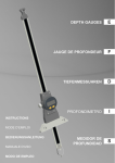
F
Unité d’affichage pour palpeurs
Anzeige-Einheit für Messtaster
Digital unit for probes
D50S
D50S-PRO
MANUEL D’UTILISATION
BEDIENUNGS-ANLEITUNG
OPERATING INSTRUCTIONS
1
F
2
F
Table des Matières
1.
Description générale .................................................................................. 4
Face avant ................................................................................................. 4
Face arrière................................................................................................ 4
Touches de sélection ................................................................................. 5
Touche de mise à zéro ou à la valeur présélectionnée.............................. 5
Touche Print............................................................................................... 5
Touches d’introduction de la valeur de Preset ........................................... 5
Touche Fct ................................................................................................. 6
Touches de verrouillage du clavier ............................................................ 6
2.
Setup par l’unité ......................................................................................... 7
3.
Etalonnages ............................................................................................... 9
3.1 Calibration de l’unité .................................................................................. 9
3.2 Calibration pour mesure de diamètres ..................................................... 10
3.3 Appairage d’un palpeur et d’une unité d’affichage (D50S-PRO).............. 10
4.
Test de la mémoire .................................................................................. 12
5.
Connexions .............................................................................................. 13
6.
Codes des rétro-commandes................................................................... 14
7.
Fonctions des connecteurs (face arrière)................................................. 17
8.
Encombrement et fixation ........................................................................ 18
9.
Spécifications techniques de l’unité ......................................................... 19
10.
Livraison .................................................................................................. 20
11.
Accessoires en options ............................................................................ 20
1.1
1.2
1.3
1.4
1.5
1.6
1.7
1.8
3
F
1. Description générale
L’unité D50S/D50S-PRO affiche la valeur de la position des palpeurs Sylvac jusqu’à
une résolution de 0.1um. De nombreuses fonctions intégrées permettent de résoudre
la plupart des problèmes de mesures rencontrés. Il permet ainsi un emploi simple à
l’utilisation.
Au moyen de 1 unité, il est possible d’afficher les valeurs de 2 palpeurs
1.1 Face avant
Affichage
Touche de fonction
Indicateur de fonction
Correction point
par point
Touche PRINT
Touches de sélection
Touche d’incrémentation
verticale du Preset
Touche de mise à zéro
ou valeur présélectionnée
Touche d’incrémentation
horizontale du Preset
1.2 Face arrière
Allumage/extinction
Connecteur chargeur
Connecteurs palpeurs
4
Connecteur contact externe
Connecteur RS232
F
1.3 Touches de sélection
Conversion directe mm/in ou in/mm
Choix de la résolution de l’affichage
0.001 – 0.0001 mm / 0.0001 - 0.00001 ‘’
Choix de la direction de mesure
+/-
Choix du mode de mesure
Rel (relative) ou Abs (absolue)
1.4 Touche de mise à zéro ou à la valeur présélectionnée
Pression courte : active la mise à zéro ou la valeur de présélection
mémorisée.
Pression longue : active l’affichage d’introduction du preset
Conseil : Lors des mesures, il est recommandé de vérifier
régulièrement la référence (zéro ou valeur présélectionnée)
1.5 Touche Print
Pression courte : Envoie la valeur affichée sur le port RS-232.
1.6 Touches d’introduction de la valeur de Preset
Pression
déplace la sélection d’un digit depuis la
gauche vers la droite.
Pression
change la valeur du digit depuis 1 à 9 .
La sélection du signe +/- doit se faire dans le premier digit de
gauche.
Mémoriser la valeur en pressant la touche PRESET.
* Valeur maximale de Preset : +/- 400mm / 15’’
5
F
1.7 Touche Fct
Fonction Cha 1
Fonction de base : L’unité affiche la valeur du palpeur n°1
Fonction Cha 2
Pression courte : L’unité affiche la valeur du palpeur n°2
Fonction Cha 1-2
Pression courte : L’unité affiche la différence entre les
valeurs des palpeurs n°1 – n°2
Fonction Cha 1+2
Pression courte: L’unité affiche la somme des valeurs des
palpeurs n°1 + n°2
*Les paramètres d’affichage (unités, résolution, ect..) sont
indépendants pour Cha 1 et Cha 2. Les fonctions différence
et somme utilisent les paramètres du Cha 1.
1.8 Touches de verrouillage du clavier
Pression longue : ~4 sec. sur une de ces touches verrouille la touche et
affiche « Loc on ».
Pour déverrouiller cette touche, appuyer jusqu’à ce
que l’affichage indique « Loc oFF »
Voir aussi (dé)-verrouillage général du clavier dans le
chapitre 2.
6
F
2. Setup par l’unité
Presser la touche Fct en enclenchant l’unité(ON)
(simultanément)
+
Fct
SEt
Loc oFF
Foot
1
LOC OFF = Clavier activé
LOC ON = Clavier désactivé
Fonctions du contact externe
Foot 1 : Print
Foot 2 : Mise à zéro
Foot 3 : Preset
Foot 4 : Changement de canal
Foot 5 : Print + changement de canal
Foot 6 : Preset puis Print
Cor1 oFF
Cor1 on : Active la correction point par point
du palpeur 1
Cor1 oFF : Désactive la correction point par
point du palpeur 1
Cor2 oFF
Cor2 on : Active la correction point par point
du palpeur 2
Cor2 oFF : Désactive la correction point par
point du palpeur 2
Seconde partie du diagramme, voir page suivante
7
F
Première partie du diagramme, voir page précédente
bEEP on
SOFt 2.3
bEEP on : Active le buzzer
bEEP oFF : Désactive le buzzer
Version du programme
26. 09. 07
Date de la version du programme
Id = 263
N° d’identification de l’unité
FAC rST
Reset de l’unité (paramètres usine sauf
calibration. Voir chapitre 3)
La pression de la touche Fct exécute la sortie du
mode Fct Set (dans tous les sous-menus)
8
F
3. Etalonnages
3.1 Calibration de l’unité
La calibration de l’unité consiste à entrer 2 points de référence sur la course du
palpeuret à spécifier le déplacement entre ces deux points. A répéter pour les 2
canaux si nécessaire.
L’unité est calibrée d’usine avec un palpeur étalon. Si l’unité n’est pas calibrée, la
fonction de calibration est automatiquement appelée lors de la mise sous tension de
l’unité.
+
Pour une nouvelle calibration, presser sur la touche Preset en
enclenchant l’unité (ON) (simultanément).
Prob = 2
Prob = 1
Prob =1,2
Calibration du canal 1 ou
Calibration du canal 2 ou
Calibration des 2 canaux (1 et 2)
rEF0 CH1
Positionner le palpeur sur la référence 0
….
Acquisition de la référence 0
rEF1 CH1
Introduire la référence 1 (valeur cale étalon) à l’aide des
touches
010.0000
et
puis positionner le palpeur sur la
référence 1.
Seconde partie du diagramme, voir page suivante
9
F
Première partie du diagramme, voir page précédente
….
0.0000
Acquisition de la référence 1
Retour à la valeur du canal 1
Une erreur lors de la calibration affiche le message
rEF1 Err
ou
rEF2 Err pour le canal 2
Si un canal n’est pas calibré, l’unité affiche
CAL 1 Err
CAL 2 Err
CAL
Err
suivant la fonction courante active.
Si un palpeur n’est pas connecté, l’unité affiche
no Prob 1
no Prob 2
no Prob
suivant la fonction courante active
Si l’on presse sur Preset alors que le canal est en mode absolu (Abs), l’affichage
indique brièvement Abs.
3.2 Calibration pour mesure de diamètres
L'unité peut être calibrée pour la mesure des diamètres intérieurs. Utiliser un petit
diamètre étalon comme Référence 0 et un grand diamètre étalon comme Référence
1. La valeur de calibration qui doit être introduite correspond à la différence entre les
deux diamètres. Une fois la calibration terminée, introduire la valeur du petit diamètre
dans la fonction Preset.
3.3 Appairage d'un palpeur et d'une unité d’affichage (option
disponible uniquement sur D50S-PRO)
Pour augmenter la précision de la mesure, il est possible d’appairer chaque canal de
l’unité avec son palpeur correspondant. Cette opération est indépendante de la
calibration. Elle consiste à définir une courbe de correction linéaire de au maximum
26 points sur la course du palpeur et à spécifier une correction pour chaque point. A
répéter pour les 2 canaux si nécessaire.
10
F
Exemple de correction
1) Palpeur P25 avec D50S-PRO sans correction -> erreur maximale de 1.4um
2) Mêmes instruments avec une correction sur 10 points (tous les 2.5mm) -> erreur
maximale de 0.7um
L'introduction ou la modification des points est faite dans
le canal 1 ou 2 courant, par le port RS232-C (voir les
retro-commandes COR, LCOR et NCOR
correspondantes). Une correction activée est indiquée par
la led COR. Lors de mesures simultanées avec 2 palpeurs
(Cha 1-2 ou Cha 1+2) la led n’est allumée que si les 2
canaux ont une courbe de correction.
L'introduction des points doit respecter les critères suivants :
• La numérotation des points doit être continue et doit commencer au point
numéro 0 ou au 1 (si le point 0 n'est pas introduit, il est automatiquement
défini avec une correction de valeur nulle).
• Après chaque point, le palpeur doit être déplacé toujours dans le sens de
palpeur sorti vers palpeur rentré.
• La valeur de correction est limitée à 1mm ou 0.1inch.
11
F
•
•
La différence de correction entre 2 points consécutifs est limitée à la moitié de
la distance entre ces 2 points. Exemple: pour 2 points distants de 1mm l'un de
l'autre, la différence de correction entre ces 2 points ne peut pas être plus
grande que 0.5mm.
L'unité doit être sur le canal 1 ou sur le 2 (touche Fct).
Si l'un de ces critères n'est pas respecté, le point n'est pas mémorisé et l'unité
renvoie l'erreur Err5 (fonction pas autorisée).
Procédure d’introduction d’une correction point par point
1) Préparer un jeu de cales étalons ou un instrument d’étalonnage approprié.
2) Mettre l’unité dans les modes suivants :
Haute résolution (touche Resol)
Direction de mesure positive (touche +/-)
Mesure en relatif (touche Rel/Abs)
3) Positionner le palpeur sur une cote de référence et faire un zéro (touche
Preset). Cette cote correspond en principe à la pré-course du palpeur, soit
environ 0.8mm.
4) Positionner le palpeur sur la première cale ou valeur étalon.
5) Lire la valeur affichée.
6) Introduire la première correction avec la rétro-commande COR 1/ +/-x.yyyyy.
La valeur de correction à introduire est égale à la valeur de la cale étalon
diminuée de la valeur lue à l’affichage (tenir compte du signe).
7) Répéter les points 4 à 6 pour les autres cales ou valeurs étalons.
8) Après l’introduction du dernier point, activer la courbe de correction avec la
rétro-commande COR ON.
4. Test de la mémoire
+
Effectue un test de la mémoire.
Affiche FLASH……..
….. PASSEd si le test réussi.
Si l’affichage indique MEM 0 Err,
L’unité est encore apte à mesurer correctement mais doit
rapidement être soumise à un contrôle technique.
Si l’affichage indique MEM 1 Err,
L’unité n’est plus apte à mesurer.
12
F
5. Connexions
1
1
3
5
6
3
7
4
8
Pos Désignation
1 Capuchon de protection
3
4
5
6
7
8
9
Pied de surélévation
Pédale pour contact externe
Entrée palpeur n°1
Entrée palpeur n°2
Bloc chargeur Européen 230V
Bloc chargeur Anglais 240 V
Bloc chargeur Américain 120V
Bloc chargeur Japonais 100V
Cable RS (droit) sub D 9p (M/F)
Ordinateur
N° Cde
904.4101
904.4010
904.4011
904.4012
904.4013
925.5609
13
9
F
6. Codes des rétro-commandes
Chaque rétro-commande doit être suivie d’un (CR) (Carriage Return)
Code
?
‘A’
ABS
‘B’
BEEP ?
BEEP 0 ou OFF
BEEP 1 ou ON
‘C’
CHA+
CHACHA ?
CHA 0 ou OFF
CHA 1 ou ON
COR ?
COR PP ?
COR RST
COR 0 ou OFF
COR 1 ou ON
COR PP/
+/-x.yyyyyy
‘E’
EXT1
EXT2
EXT3
EXT4
EXT5
EXT51
EXT52
EXT53
EXT54
EXT6
EXT ?
‘F’
FAC RST
FCT 1
FCT 2
FCT 3
FCT 4
FCT?
Fonction
Transmet la valeur affichée de la fonction courante (1..4)
Active le mode absolu (ABS) du canal actif
Transmet l’état du buzzer
Désactive le buzzer
Active le buzzer
Initialise l’unité dans le sens de mesure positif
Initialise l’unité dans le sens de mesure négatif
Transmet le sens de mesure actif
Fige la fonction +/Libère la fonction +/Transmet l’état de la correction point par point du canal actif
Transmet l’état de la correction d’un point du canal actif
Remise à zéro de la correction
Désactive la correction
Active la correction (indiqué par un point sur le dernier digit de
l’affichage)
Introduit ou modifie un point de la correction. PP = nombre de
points [0…25]. Correction max : 1.0mm/0.1’’
Active le mode de contact externe 1 : Print
Active le mode de contact externe 2 : Mise à zéro
Active le mode de contact externe 3 : Preset
Active le mode de contact externe 4 : Changement de canal
Active le mode de contact externe 5 : Print + changement de
canal
Active le mode de contact externe 5 : Print + changement vers le
canal 1
Active le mode de contact externe 5 : Print + changement vers le
canal 2
Active le mode de contact externe 5 : Print + changement vers les
canaux 1 et 2
Active le mode de contact externe 5 : Print + changement vers les
canaux 1 à 4
Active le mode de contact externe 6 : Preset puis Print
Transmet le mode du contact externe ?
Reset général (restaure les paramètres d’usine) , NUM=263
Active canal 1
Active canal 2
Active canal 1-2 (différence)
Active canal 1+2 (somme)
Transmet la fonction active
14
F
Code
FCT 0 ou OFF
FCT ON
‘I’
IDE ou ID?
ID
IN
‘K’
KEY0 ou OFF
KEY1 ou ON
KEY ?
‘L’
LCAL ?
LCAL jj.mm.aa
LCOR ?
LCOR jj.mm.aa
‘M’
MM
MOD ?
MOD 0 ou OFF
MOD 1 ou ON
‘N’
NCAL ?
NCAL jj.mm.aa
NCOR ?
NCOR jj.mm.aa
NUM ?
NUM XXXX
‘O’
OUT 0 ou OFF
OUT 1 ou ON
‘P’
PRE ou PRESET
PRE ?
PRE +/-xxx.yyyyyy
PRE OFF
PRE ON
PRI ou P
PRI 0 ou OFF
PRI 1 ou ON
‘R’
REL
RES1
RES2
RES3
RES4
RES ?
RES 0 ou OFF
RES ON
RST
Fonction
Fige les fonctions Fct
Libère les fonctions Fct
Transmet l’identification de l’instrument (SY263)
Transmet l’identification de l’instrument (SYL263)
Active de l’unité de mesure Inch du canal actif
Désactive le clavier (sauf print)
Active le clavier
Transmet l’état du clavier
Transmet la date de la dernière calibration
Introduit la date de la dernière calibration
Transmet la date de la dernière correction point par point
Introduit la date de la dernière correction point par point
Active l’unité de mesure millimètre
Transmet le mode actif (ABS ou REL)
Fige la fonction ABS ou REL
Libère la fonction ABS ou REL
Transmet la date de la prochaine calibration
Introduit la date de la prochaine calibration
Transmet la date de la prochaine correction point par point
Introduit la date de la prochaine correction point par point
Transmet le numéro de l’instrument
Modifie le numéro de l’instrument (0…9999)
Désactive la transmission automatique de données
Active la transmission automatique de données
Active la valeur du preset mémorisé
Transmet la valeur du Preset de la fonction active (1..4)
Introduit la valeur de Preset du canal actif (1 ou 2).
Max 400mm/15’’
Fige la fonction Preset
Libère la fonction Preset
Transmet la valeur affichée de la fonction courante (1..4)
Fige la fonction Print
Libère la fonction Print
Active le mode relatif du canal courant (1 ou 2)
Active la résolution (0.0001mm, 0.00001’’) du canal courant
Active la résolution (0.001mm, 0.0001’’ ) du canal courant
Active la résolution (0.01mm, 0.001’’) du canal courant
Active la résolution (0.1mm, 0.01’’) du canal courant
Transmet la résolution du canal courant (1 ou 2)
Fige la fonction Resol
Libère la fonction Resol
Reset de l’instrument (paramètres utilisateurs)
15
F
Code
‘S’
SET ?
Fonction
SYS RST
STO 0 ou OFF
STO 1 ou ON
STO ?
‘U’
UNI ?
UNI 0 ou OFF
UNI 1 ou ON
‘V’
VER ?
Transmet la configuration de l’instrument pour le canal courant
1 ou 2 (Unité de mesure, Résolution, Direction, Rel/Abs, affichage
figé et état du clavier).
Reset de l’instrument (paramètres utilisateurs)
Libère l’affichage
Fige l’affichage
Transmet l’état de l’affichage
Transmet l’unité de l’affichage courant (mm ou ‘’)
Fige la fonction Unit
Libère la fonction Unit
Transmet la version et la date du programme (Vx.y jj.mm.aa)
RS 232 messages d’erreurs de transmission
Code
ERR0
ERR1
ERR2
ERR4
Affichage
‘fct oFF’
‘rS Err’
‘rS codE’
‘rS FULL’
ERR5
ERR6
ERR7
ERR8
ERRA
ERRB
‘no Func’
‘rS orun’
‘rS Err’
‘rS Err’
‘MEMO Err’
‘MEM1 Err’
P1 ERR
P2 ERR
P12 ERR
‘no Prob1’
‘no Prob2’
‘no Prob’
Type d’erreur
Commande non exécutée, fonction désactivée
Erreur de parité
Trame inconnue
Dépassement de capacité, plus de 200 caractères sans
CR
Commande non exécutée, fonction pas autorisée.
Erreur overrun
Erreur de trame
Erreur transmission interrompue
Erreur non critique de mémoire Flash
Erreur critique de mémoire Flash, requiert un acquittement
au clavier.
Palpeur 1 non connecté
Palpeur 1 non connecté
Palpeurs 1 et 2 non connectés
Paramètres RS 232 de l’unité
Baud rate
Parité
Bit data
Stop bit
Contrôle flux
4800 (vitesse de transmission)
Paire (even)
7
2
aucun
16
F
7. Fonctions des connecteurs (face arrière)
Connecteur enclenchement/déclenchement
Broche 1
Broche 2
Broche 3
Masse
Entrée + 8.5 V
Entrée contact externe 1 (signal = 0 Volt)
Broche 1
Broche 2
Broche 3
Masse
Entrée + 8.5 V
Entrée contact externe 1 (signal = 0 Volt)
Broche 1
Broche 2
Broche 3
Broche 4
Broche 5
Broche 6
Broche 7
Broche 8
Broche 9
Sortie chargeur 8.5 V / 300 mA
TXD = entrée RS 232 C
RXD = sortie RS 232 C
pas utilisé
SG = masse
pas utilisé
pas utilisé
pas utilisé
Sortie chargeur 8.5 V / 300 mA
17
F
8. Encombrement et fixation
Front side
M4
M4
31.5
M4
21.5
M4
10
160
75
180
21.5
50
31.5
10
M3
M3
M3
M3
12
max
50
49.4
Front
side
18
75
10 max
F
9. Spécifications techniques de l’unité
Boîtier
Plastique Terblend (=ASA + polycarbonate) :
Résistant aux alcools, glycols et la plupart des huiles et
graisses, de même qu’aux acides dilués, et à l’eau.
Non résistant aux hydrocarbures aromatiques, esters,
acétones, aux acides minéraux concentrées, au gaz
ammoniac et à ses dilutions
Face avant
Polyester
Face arrière
Aluminium verni
Clavier
Dômes plastiques à rétroaction tactile
Dimensions
Largeur 180 mm, profondeur 75mm , hauteur 50 mm
Protection
IP 40 (selon spécifications IEC 529)
Poids
0.3 kg
Consommation
<250mA sur bloc chargeur Sylvac
Température de stockage Entre –20°C et +45°C
Température d’utilisation
Entre +5°C et +40°C
Dimensions (chiffres)
hauteur 13.2 mm
Stabilisation thermique à
l‘enclenchement
15 minutes minimum.
Résolution
0.1 um (.00001’’)
Justesse (précision)
Palpeur P2 : 1.5um
Palpeur P5 : 1.6um
Palpeur P10 : 1.6um
Palpeur P25 : 1.9um
Palpeur P50 : 3.9um
Justesse (précision)
Palpeur et unité appariés
Palpeur P2 : 0.5um
Palpeur P5 : 0.6um
Palpeur P10 : 0.6um
Palpeur P25 : 0.8um
Palpeur P50 : 1.5um
Nombre de
rafraîchissements par
seconde
0.1um : 3/s selon palpeur (1 canal)
1.5/s selon palpeurs (2 canaux)
1um : 10/s selon palpeur (1 canal)
5/s selon palpeurs (2 canaux)
19
F
10. Livraison
Emballage en carton comprenant :
N° de commande
804.1050
1 unité D50S
comprenant :
Nb
1
1
ou
ou
ou
8
2
1
Désignation
Unité d’affichage D50S
Bloc chargeur Européen 230 V
Bloc chargeur Anglais 240V
Bloc chargeur Américain 120V
Bloc chargeur Japonais 100V
Capuchon de protection
Pied de surélévation
Mode d’emploi
N° Cde
804.1050.10
904.4010
904.4011
904.4012
904.4013
681072-100
Emballage en carton comprenant :
N° de commande
804.1060
1 unité D50S-PRO
comprenant :
Nb
1
1
ou
ou
ou
8
2
1
Désignation
Unité d’affichage D50S-PRO
Bloc chargeur Européen 230 V
Bloc chargeur Anglais 240V
Bloc chargeur Américain 120V
Bloc chargeur Japonais 100V
Capuchon de protection
Pied de surélévation
Mode d’emploi
N° Cde
804.1060
904.4010
904.4011
904.4012
904.4013
681072-100
11. Accessoires en options
Nb
1
1
1
Désignation
Pédale pour contact externe
Câble RS (droit) sub-D 9p (m/f), 3 mètres
Jeu de 4 étriers de clipsage
20
N° Cde
904.4101
925.5609
-
F
21
D
Inhaltsverzeichnis
1.
Allgemeine Beschreibung ........................................................................ 23
Frontansicht ............................................................................................. 23
Rückansicht ............................................................................................. 23
Funktionswahl-Tasten.............................................................................. 24
Nulleinstelltaste oder Eingabe eines Vorwahlwertes (Preset).................. 24
Print Taste ............................................................................................... 24
Vorwahlwert-Eingabetaste (Preset) ......................................................... 24
Taste Fct.................................................................................................. 25
Tasten zur Blockierung der Tastatur ........................................................ 25
2.
Konfigurieren der Einheit ......................................................................... 26
3.
Kalibrieren................................................................................................ 28
3.1 Kalibrieren der Einheit.............................................................................. 28
3.2 Kalibrieren für Durchmessermessungen.................................................. 29
3.3 Paarung eines Messtasters mit einer Anzeigeinheit (D50S-PRO) ........... 29
4.
Speichertest ............................................................................................. 31
5.
Verbindungen........................................................................................... 32
6.
Adressen der Rückbefehle....................................................................... 33
7.
Steckerfunktionen (Rückansicht) ............................................................. 36
8.
Abmasse und Befestigung ....................................................................... 37
9.
Technische Daten der Anzeigeeinheit ..................................................... 38
10.
Lieferung.................................................................................................. 39
11.
Zubehör auf Bestellung............................................................................ 39
1.1
1.2
1.3
1.4
1.5
1.6
1.7
1.8
22
D
1. Allgemeine Beschreibung
Die D50S/D50S-PRO Einheit zeigt die Positionswerte der Sylvac Messtaster bis zu
einer Auflösung von 0.1 ųm an. Zahlreiche integrierte Funktionen ermöglichen die
Ausführung von fast allen anfallenden Messproblemen. Eine einfache und schnelle
Bedienung wird garantiert.
Es ist möglich, mit einer Einheit die Werte von zwei Messtastern anzuzeigen.
1.1 Frontansicht
Messwertanzeige
Funktionstasten
Funktionshinweise
Korrectur pro Punkt
PRINT Taste
Funktionswahl-Tasten
Vorwahlwert- Einstelltaste,
Ziffernauswahl
Nulleinstelltaste oder
Vorwahlwert-Eingabetaste,
Ziffern-Inkrementierung
Eingabe eines Vorwahlwertes (Preset)
1.2 Rückansicht
Ein- / Ausschalter
Anschluss für Ladegerät
Messstaster-Anschluss
23
Anschluss für externen Kontakt
RS232 Anschluss
D
1.3 Funktionswahl-Tasten
Direktumschaltung von mm/in oder in/mm
Wahl der Auflösung der Anzeige
0.001 – 0.0001 mm / 0.0001 - 0.00001 ‘’
Wahl der Messrichtung
+/-
Wahl des Messmodus
Rel (relativ) oder Abs (absolut)
1.4 Nulleinstelltaste oder Eingabe eines Vorwahlwertes (Preset)
Kurzes Drücken : Nulleinstellung oder Eingabe des gespeicherten
Vorwahlwertes.
Langes Drücken : Anzeige für die Vorwahlwerteingabe wird aktiviert
Bemerkung : Während der Messungen sollte regelmässig die Referenz
(Null oder Vorwahlwert ) kontrolliert werden.
1.5 Print Taste
Kurzes Drücken : Sendet den angezeigten Wert an den RS-232 Port.
1.6 Vorwahlwert-Eingabetaste (Preset)
Druck auf
nach rechts.
verschiebt die Wahl einer Ziffer von links
Druck auf
verschiebt den Ziffernwert von 1 bis 9 .
Die Vorzeichenwahl +/- wird über die erste Ziffer links
ausgeführt.
Den eingegebenen Wert durch Drücken der PRESET Taste
speichern.
* Maximaler Vorwahlwert (Preset) : +/- 400 mm / 15’’
24
D
1.7 Taste Fct
Funktion Cha 1
Grundfunktion: Die Einheit zeigt den Wert von Taster Nr. 1 an.
Funktion Cha 2
Kurzer Druck: Die Einheit zeigt den Wert von Taster Nr. 2 an.
Funktion Cha 1-2
Kurzer Druck: Die Einheit zeigt die Differenz der Werte von
Taster Nr. 1 – Nr. 2 an.
Funktion Cha 1+2
Kurzer Druck: Die Einheit zeigt die Summe der Werte von
Taster Nr. 1 + Nr. 2 an.
*Die Anzeigeparameter (Masseinheit, Auflösung, usw.) sind für
Cha 1 und Cha 2 unabhängig voneinander. Die Funktionen
Differenz und Summe benutzen die Parameter von Cha 1.
1.8 Tasten zur Blockierung der Tastatur
Langer Druck:
~4 Sek. auf eine der nebenstehenden Tasten sperrt die
Taste und
« Loc on » wird angezeigt.
Um die Taste zu entsperren, diese so lange drücken bis
« Loc oFF » angezeigt wird.
Siehe auch ″Generelles (Ent-) Sperren″ der Tastatur in
Kapitel 2.
25
D
2. Konfigurieren der Einheit
Die Taste Fct drücken während dem Einschalten (ON) der
Einheit (gleichzeitig)
+
Fct
SEt
Loc oFF
LOC OFF = Tastatur ist aktiviert
LOC ON = Tastatur ist nicht aktiviert
Foot
1
Funktion des externes Kontakt
Foot 1 : Print
Foot 2 : Nulleinstellung
Foot 3 : Preset
Foot 4 : Kanalwechsel
Foot 5 : Print + Kanalwechsel
Foot 6 : Preset, nacher Print
Cor1 oFF
Cor1 on : Aktiviert die Korrectur (Punkt für
Punkt) von Messtaster 1
Cor1 oFF : Entaktiviert die Korrectur (Punkt für
Punkt) von Messtaster 1
Cor2 oFF
Cor2 on : Aktiviert die Korrectur (Punkt für
Punkt) von Messtaster 2
Cor2 oFF : Entaktiviert die Korrectur (Punkt für
Punkt) von Messtaster 2
Zweiter Teil des Diagramms, siehe folgende Seite
26
D
Erster Teil des Diagramms, siehe vorhergehende Seite
bEEP on
SOFt 2.3
bEEP on : Buzzer Freigeben
bEEP oFF : Buzzer sperren
Programmversion
26. 09. 07
Datum der Programmversion
Id = 263
Identifikations-Nr. der Anzeigeeinheit
FAC rST
Reset der Einheit (ab Werk eingestellte Parameter
ausser Kalibrierung. Siehe Kapitel 3)
Durch Druck auf die Taste Fct wird der Fct Set Modus
verlassen (für alle Untermenüs gültig)
27
D
3. Kalibrieren
3.1 Kalibrieren der Einheit
Die Kalibrierung der Einheit entsteht durch das Eingeben von zwei Referenzpunkten
verteilt auf den Messbereich des Tasters und Festhalten der Differenz dieser zwei
Punkte. Wenn nötig, für beide Kanäle wiederholen.
Die Einheit wird im Werk mit einem Eichmaster (Messtaster) kalibriert. Ist die Einheit
nicht kalibriert, wird die entsprechende Kalibrierfunktion automatisch nach dem
Einschalten dieser angezeigt.
+
Für die Durchführung einer Neukalibrierung Taste Preset
drücken und die Einheit einschalten (ON) (gleichzeitig).
Prob = 2
Prob = 1
Prob =1,2
Kalibrieren von Kanal 1 oder
Kalibrieren von Kanal 2 oder
Kalibrieren beider Kanäle (1 und 2)
rEF0 CH1
Mit dem Messtaster die Referenz 0 antasten
….
Erwerb der Referenz 0
rEF1 CH1
Die Referenz 1 (Wert des Eichendmasses) durch aktivieren der
Tasten
010.0000
und
eingeben und dann mit dem
Messtaster die Referenz 1, das Endmass, antasten.
Zweiter Teil des Diagramms, siehe folgende Seite
28
D
Erster Teil des Diagramms, siehe vorhergehende Seite
….
0.0000
Erwerb der Referenz 1
Zurück zum Wert auf Kanal 1
Ein Fehler während dem Kalibrieren wird mit
rEF1 Err für Kanal 1
oder
rEF2 Err für Kanal 2, angezeigt
Wurde ein Kanal nicht kalibriert, zeigt die Einheit folgendes an:
CAL 1 Err
CAL 2 Err
CAL
Err
je nach der momentan aktivierten Funktion.
Wurde kein Messtaster angeschlossen, zeigt die Anzeige folgendes an:
no Prob 1
no Prob 2
no Prob
je nach der momentan aktivierten Funktion
Wird die Preset Taste gedrückt, wenn sich der Kanal im absoluten (Abs) Messmodus
befindet, wird kurz Abs angezeigt.
3.2 Kalibrieren für Durchmessermessungen
Die Einheit kann für das Messen von Innendurchmesser kalibriert werden. Zu
verwenden sind ein kleiner Eichring als Referenz 0 und ein grosser Eichring als
Referenz 1. Der einzugebende Kalibrierwert entspricht der Differenz der beiden
Eichring-Durchmesser. Nach Beenden der Kalibrierung, den Wert des kleinen
Eichrings als Vorwahlwert (Preset) eingeben.
3.3 Paarung eines Messtasters mit einer Anzeigeeinheit (Option nur
für D50S-PRO verfügbar)
Die Messgenauigkeit kann erhöht werden indem jeder Kanal der Einheit mit seinem
zugeteilten Taster gepaart wird. Dieser Vorgang ist von der Kalibrierung unabhängig.
Er besteht darin, eine Korrektur von bis max. 26 Punkten über den Messbereich des
Tasters durchzuführen und die Korrektur pro Punkt festzuhalten. Wenn nötig, für
beide Kanäle wiederholen.
29
D
Korrekturbeispiel
1) Messtaster P25 mit D50S-PRO ohne Korrektur —> maximale Abweichung 1,4 µm
2) Selbe Messinstrumente, jedoch mit Korrektur an 10 Punkten (alle 2,5 mm) —>
maximale Abweichung 0,7 µm
Die Eingabe oder Änderung der Punkte wird auf Kanal 1
oder 2 über den RS232-C Anschluss durchgeführt (siehe
Rückbefehle COR, LCOR und NCOR). Eine aktivierte
Korrektur wird durch das led COR vermerkt. Bei
gleichzeitigem Messen beider Kanäle (Cha 1-2 oder Cha
1+2) wird das Led nur aufleuchten wenn beide Kanäle
über eine Korrektur verfügen.
Die Eingabe der Punkte muss folgende Kriterien berücksichtigen:
• Die Nummerierung der Punkte muss fortlaufend sein und bei Punkt Nummer 0
oder 1 beginnen. (Falls Punkt 0 nicht eingegeben ist, wird er automatisch mit
einem Korrekturwert null definiert)
• Nach jedem Punkt muss die Tastspitze immer in hineingehender Richtung
verschoben werden.
• Der Wert der Korrektur ist auf 1mm oder 0.1inch beschränkt.
30
D
•
•
Die Korrekturdifferenz von 2 aufeinanderfolgenden Punkten ist auf die Hälfte
dieser zwei Punkte beschränkt. Beispiel: Für zwei aufeinanderfolgende Punkte
mit einem Abstand von 1mm kann die Korrekturdifferenz nicht grösser als
0.5mm sein.
Die Anzeigeeinheit muss auf Kanal 1 oder 2 eingestellt sein (Taste Fct).
Bei Nichteinhalten obiger Prozedur wird der Korrekturpunkt nicht gespeichert und die
Anzeigeeinheit sendet die Meldung Err5 (Funktion nicht zugelassen).
Vorgang der Korrektureingabe Punkt nach Punkt
1) Vorbereiten eines Parallelendmass-Satzes oder eines sonstigen angepassten
Kalibrierinstrumentes
2) Einheit in folgende Modus stellen :
Hohe Auflösung (TasteResol)
Positive Messrichtung (Taste +/-)
Relative Messung (Taste Rel/Abs)
3) Messtaster auf Referenzmass positionieren und nullen (Taste Preset). Dieser
Punkt ist grundsätzlich der Anfangsabstand des Messtasters, dh etwa 0.8mm.
4) Erstes Endmass unter den Taster schieben.
5) Angezeigter Wert ablesen.
6) Erste Korrektur mittels Rückbefehl COR 1/ +/-x.yyyyy eingeben.
Der einzugebende Korrekturwert entspricht des Wertes des Endmasses minus
des angezeigten Wertes (Zeichen +/- beachten).
7) Vorgang 4 bis 6 für die weiteren Endmasse wiederholen.
8) Nach Eingabe des letzten Korrekturpunktes, aktivieren des
Korrekturdiagramms mittels Rückbefehl COR ON.
4. Speichertest
+
Führt einen Speichertest aus.
Anzeige von FLASH……..
….. PASSEd wenn der Test positiv ist.
Wird MEM 0 Err angezeigt,
kann die Einheit noch korrekt messen, sollte aber schnellstens
einer technischen Kontrolle unterzogen werden.
Wird MEM 1 Err angezeigt,
ist die Einheit nicht mehr imstande zu messen.
31
D
5. Verbindungen
1
1
3
5
6
3
7
4
8
Pos. Bezeichnung
1
Schutzkappe
3
4
5
6
7
8
9
Erhöhungsfuss
Fusspedal für externen Kontakt
Eingang Messtaster Nr. 1
Eingang Messtaster Nr. 2
Ladegerät, Europa 230V
Ladegerät, England 240 V
Ladegerät, Amerika 120V
Ladegerät, Japan 100V
RS Kabel (gerade) sub D 9p (m/w)
Rechner
Bestell-Nr.
9
904.4101
904.4010
904.4011
904.4012
904.4013
925.5609
32
D
6. Adressen der Rückbefehle
Jedem Rückbefehl muss der Befehl ″CR″ (Carriage Return) folgen
Kode
?
‘A’
ABS
‘B’
BEEP ?
BEEP 0 oder
OFF
BEEP 1 oder ON
‘C’
CHA+
CHACHA ?
CHA 0 oder OFF
CHA 1 oder ON
COR ?
COR PP ?
COR RST
COR 0 oder OFF
COR 1 oder ON
COR PP/
+/- x.yyyyyy
‘E’
EXT1
EXT2
EXT3
EXT4
EXT5
EXT51
EXT52
EXT53
EXT54
EXT6
EXT ?
‘F’
FAC RST
FCT 1
FCT 2
FCT 3
FCT 4
FCT?
Funktion
Sendet den, für die laufende Funktion angezeigten Wert (1..4)
Aktiviert den absoluten (ABS) Messmodus des aktiven Kanals
Sendet den Buzzer Zustand (ein/aus)
Buzzer sperren
Buzzer Freigeben
Initialisiert die Einheit für eine positive Messrichtung
Initialisiert die Einheit für eine negative Messrichtung
Sendet die aktivierte Messrichtung
Blockiert die Funktion +/Gibt die Funktion +/- wieder frei
Sendet das Status der Korrectur pro Punkt des aktiven Kanals
Sendet das Status der Korrectur eines Punkt des aktiven Kanals
Nullüberreichung der Korrektur pro Punkt
Entaktiviert die Korrektur pro Punkt
Aktiviert die Korrektur pro Punkt (angegeben durch einen Punkt
über die letzte Stelle der Anzeige)
Eingeführt oder ändert ein Punkt der Korrektur. PP = Anzahl der
Punkte [0…25]. Max Korrektur : 1.0mm/0.1’’
Aktiviert den externen Kontaktmodus 1 : Print (drucken)
Aktiviert den externen Kontaktmodus 2 : Nulleinstellung
Aktiviert den externen Kontaktmodus 3 : Preset (Vorwahlwert)
Aktiviert den externen Kontaktmodus 4 : Kanalwechsel
Aktiviert den externen Kontaktmodus 5 : Print + Kanalwechsel
Aktiviert den externen Kontaktmodus 5 : Print + Änderung in
Richtung Kanals 1
Aktiviert den externen Kontaktmodus 5 : Print + Änderung in
Richtung Kanals 2
Aktiviert den externen Kontaktmodus 5 : Print + Änderung in
Richtung Kanals 1 und 2
Aktiviert den externen Kontaktmodus 5 : Print + Änderung in
Richtung Kanals 1 bis 4
Aktiviert den externen Kontaktmodus 6 : Preset, nacher Print
Sendet den Modus des externen Kontakts ?
Generelles Reset (stellt die Grundparameter ab Werk wieder her),
NUM=263
Aktiviert Kanal 1
Aktiviert Kanal 2
Aktiviert Kanal 1-2 (Differenz)
Aktiviert Kanal 1+2 (Summe)
Sendet die aktive Funktion
33
D
Kode
FCT 0 oder OFF
FCT ON
‘I’
IDE oder ID?
ID
IN
‘K’
KEY0 oder OFF
KEY1 oder ON
KEY ?
‘L’
LCAL ?
LCAL dd.mm.yy
LCOR ?
LCOR dd.mm.yy
‘M’
MM
MOD ?
MOD 0 oder OFF
MOD 1 oder ON
‘N’
NCAL ?
NCAL dd.mm.yy
NCOR ?
NCOR dd.mm.yy
NUM ?
NUM XXXX
‘O’
OUT 0 oder OFF
OUT 1 oder ON
‘P’
PRE oder
PRESET
PRE ?
PRE +/-xxx.yyyyyy
PRE OFF
PRE ON
PRI ou P
PRI 0 ou OFF
PRI 1 ou ON
‘R’
REL
RES1
RES2
RES3
RES4
RES ?
RES 0 ou OFF
RES ON
Funktion
Blockiert die Funktion Fct
Gibt die Funktion Fct wieder frei
Sendet die Identifikation der Einheit (SY263)
Sendet die Identifikation der Einheit (SYL263)
Aktiviert die Masseinheit ″Inch″ des aktiven Kanals
Entaktiviert die Tastatur (Print ausgenommen)
Aktiviert die Tastatur
Sendet den Status der Tastatur
Sendet die Datum der letzten Kalibrierung
Gibt die Datum der letzten Kalibrierung
Sendet die Datum der letzten Korrektur pro Punkt
Gibt die Datum der letzten Korrektur pro Punkt
Aktiviert die Masseinheit ″mm″
Sendet den aktiven Messmodus (ABS oder REL)
Blockiert die Funktion ABS oder REL
Gibt die Funktion ABS oder REL wieder frei
Sendet die Datum der nächsten Kalibrierung
Gibt die Datum der nächsten Kalibrierung
Sendet die Datum der nächsten Korrektur pro Punkt
Gibt die Datum der nächsten Korrektur pro Punkt
Sendet die Nummer der Anzeigeeinheit
Korrigiert die Nummer der Anzeigeeinheit (0…9999)
Automatische Datenübertragung sperren
Automatische Datenübertragung Freigeben
Aktiviert den gespeicherten Vorwahlwert (Preset)
Sendet den Presetwert der aktiven Funktion (1..4)
Gibt den Presetwert des aktiven Kanals (1 oder 2) ein.
Max 400mm/15’’
Blockiert die Preset Funktion
Gibt die Preset Funktion wieder frei
Sendet den angezeigten Wert der laufenden Funktion (1..4)
Blockiert die Print (Ausdruck) Funktion
Gibt die Print Funktion wieder frei
Aktiviert den ″relativen″ Messmodus des aktiven Kanals (1 oder 2)
Aktiviert die Auflösung (0.0001mm, 0.00001’’) des aktiven Kanals
Aktiviert die Auflösung (0.001mm, 0.0001’’ ) des aktiven Kanals
Aktiviert die Auflösung (0.01mm, 0.001’’) des aktiven Kanals
Aktiviert die Auflösung (0.1mm, 0.01’’) des aktiven Kanals
Sendet die Auflösung des aktiven Kanals (1 oder 2)
Blockiert die Funktion ″Resol″ (Auflösung)
Gibt die Funktion ″Resol″ wieder frei
34
D
Kode
RST
‘S’
SET ?
Funktion
Reset der Anzeigeeinheit (Parameter des Kunden)
SYS RST
STO 0 ou OFF
STO 1 ou ON
STO ?
‘U’
UNI ?
UNI 0 ou OFF
UNI 1 ou ON
‘V’
VER ?
Sendet die Konfigurierung der Einheit für den aktiven Kanal
1 oder 2 (Masseinheit, Auflösung, Messrichtung, Rel/Abs,
Anzeige blockiert und Status der Tastatur).
Reset der Einheit (Parameter des Kunden)
Gibt die Messwertanzeige frei
Blockiert die Messwertanzeige
Sendet den Status der Messwertanzeige
Sendet die aktivierte Masseinheit (mm oder ″)
Blockiert die Funktion der Masseinheit
Gibt die Funktion der Masseinheit wieder frei
Sendet die Version und das Software-Datum (Vx.y dd.mm.yy)
RS 232 Fehlermeldungen bei Übertragungen
Kode
ERR0
ERR1
ERR2
ERR4
ERR5
ERR6
ERR7
ERR8
ERRA
ERRB
Anzeige
‘fct oFF’
‘rS Err’
‘rS codE’
‘rS FULL’
‘no Func’
‘rS orun’
‘rS Err’
‘rS Err’
‘MEMO Err’
‘MEM1 Err’
P1 ERR
P2 ERR
P12 ERR
‘no Prob1’
‘no Prob2’
‘no Prob’
Fehlertyp
Befehl nicht ausgeführt, Funktion nicht aktiviert
Paritätsfehler
Raster unbekannt
Überschreiten der Kapazität, mehr als 200 Ziffer ohne CR
Befehl nicht ausgeführt, Funktion nicht zugelassen
Overrun-Fehler
Rasterfehler
Fehler Übertragung unterbrochen
Nicht kritischer Fehler des Flash-Speichers
Kritischer Fehler des Flash-Speichers, erfordert eine
Bestätigung über Tastatur
Messtatser 1 nicht verbunden
Messtatser 2 nicht verbunden
Messtatser 1 und 2 nicht verbunden
RS 232 Parameter der Anzeigeeinheit
Baudrate
Parität
Data Bits
Stop Bits
Datenflusskontrolle
4800 (Übertragungsgeschwindigkeit)
gleich (even)
7
2
Keine
35
D
7. Steckerfunktionen (Rückansicht)
Ein- / Ausschalter
Stift 1
Stift 2
Stift 3
Erde
Eingang + 8.5 V
Eingang externer Kontakt 1 (Signal = 0 Volt)
Stift 1
Stift 2
Stift 3
Erde
Eingang + 8.5 V
Eingang externer Kontakt 1 (Signal = 0 Volt)
Stift 1
Stift 2
Stift 3
Stift 4
Stift 5
Stift 6
Stift 7
Stift 8
Stift 9
Ausgang Ladegerät 8.5 V / 300 mA
TXD = Eingang RS 232 C
RXD = Ausgang RS 232 C
nicht verwendet
SG = Erde
nicht verwendet
nicht verwendet
nicht verwendet
Ausgang Ladegerät 8.5 V / 300 mA
36
D
8. Abmasse und Befestigung
Front side
M4
M4
31.5
M4
21.5
M4
10
160
75
180
21.5
50
31.5
10
M3
M3
M3
M3
12
max
50
49.4
Front
side
37
75
10 max
D
9. Technische Daten der Anzeigeeinheit
Gehäuse
Terblendplastik (=ASA + Polycarbonat) :
Wiederstandsfähig gegen Alkohol, Glykole und den
meisten Ölen und Fetten sowie gegen verdünnte Säuren
und Wasser.
Nicht wiederstandsfähig gegen aromatische Kohlenwasserstoffe, Ester, Aceton, konzentrierte Mineralsäuren,
Ammoniakgas und seine Verdünnungen
Frontansicht
Polyester
Rückansicht
Aluminium, lackiert
Tastatur
Plastikkuppen mit Taktilrückwirkung
Abmasse
Breite 180 mm, Tiefe 75mm , Höhe 50 mm
Schutzart
IP 40 (nach IEC 529 Angaben)
Gewicht
0.3 kg
Verbrauch
<250mA auf Sylvac Ladegerät
Lagertemperatur
zwischen –20°C und +45°C
Betriebstemperatur
zwischen +5°C und +40°C
Abmasse der Ziffern
Höhe 13.2 mm
Thermische Stabilisation
nach dem Einschalten
Minimum 15 Minuten
Auflösung
0.1 um (.00001’’)
Messgenauigkeit
Messtaster P2 : 1.5um
Messtaster P5 : 1.6um
Messtaster P10 : 1.6um
Messtaster P25 : 1.9um
Messtaster P50 : 3.9um
Messgenauigkeit
Taster mit Einheit
zusammenschalten
Messtaster P2 : 0.5um
Messtaster P5 : 0.6um
Messtaster P10 : 0.6um
Messtaster P25 : 0.8um
Messtaster P50 : 1.5um
Anzahl der Anzeigefolgen 0.1um : 3/s nach dem Messtaster (1 Kanal)
1.5/s nach der Messtastern (2 Kanäle)
1um : 10/s nach dem Messtaster (1 Kanal)
5/s nach der Messtastern (2 Kanäle)
38
D
10. Lieferung
Kartonverpackung, beinhaltend :
Bestell-Nr.
804.1050
1 Anzeigeeinheit D50S
beinhaltend :
Anz.
1
1
oder
oder
oder
8
2
1
Bezeichnung
Anzeigeeinheit D50S
Ladegerät, Europa 230 V
Ladegerät, England 240V
Ladegerät, America 120V
Ladegerät, Japan 100V
Schutzkappe
Erhöhungsfuss
Gebrauchsanleitung
Bestell-Nr.
804.1050
904.4010
904.4011
904.4012
904.4013
681072-100
Kartonverpackung, beinhaltend :
Bestell-Nr.
804.1060
1 Anzeigeeinheit D50S-PRO
beinhaltend :
Anz.
1
1
oder
oder
oder
8
2
1
Bezeichnung
Anzeigeeinheit D50S-PRO
Ladegerät, Europa 230 V
Ladegerät, England 240V
Ladegerät, America 120V
Ladegerät, Japan 100V
Schutzkappe
Erhöhungsfuss
Gebrauchsanleitung
Bestell-Nr.
804.1060
904.4010
904.4011
904.4012
904.4013
681072-100
11. Zubehör auf Bestellung
Anz.
1
1
1
Bezeichnung
Fusspedal für externen Kontakt
Kabel RS (gerade) sub-D 9p (m/w), 3 Meter lang
Satz von 4 Klemmbügeln
39
Bestell-Nr.
904.4101
925.5609
-
E
40
E
Contents
1.
General description.................................................................................. 42
Front of unit.............................................................................................. 42
Rear of unit .............................................................................................. 42
Selection keys.......................................................................................... 43
Zero setting or preset value setting key ................................................... 43
Print key................................................................................................... 43
Introduction of preset value keys ............................................................. 43
Fct key ..................................................................................................... 44
Keyboard locking keys ............................................................................. 44
2.
Setup on the unit...................................................................................... 45
3.
Calibrations .............................................................................................. 47
3.1 Calibration of the unit ............................................................................... 47
3.2 Calibration for diameter measurment....................................................... 48
3.3 Matching of a probe and a unit (D50S-PRO) ........................................... 48
4.
Test of memory ........................................................................................ 50
5.
Connections ............................................................................................. 51
6.
Codes for remote commands................................................................... 52
7.
Functions of connectors (rear panel) ....................................................... 55
8.
Sizes and fixing........................................................................................ 56
9.
Technical specifications ........................................................................... 57
10.
Delivery .................................................................................................... 58
11.
Optional accessories................................................................................ 58
1.1
1.2
1.3
1.4
1.5
1.6
1.7
1.8
41
E
1. General description
The D50S/D50S-PRO unit displays the absolute or real displacement of Sylvac
probes. Highest resolution is 0.1um. Numerous integrated functions will resolve most
metrological problems and ease of use.
It is possible to connect and display up to 2 Sylvac probes
1.1 Front of unit
Display
Function key
Function indicator
Point per point
Correction
PRINT key
Selection keys
Preset
Digit incrementation
Preset
Digit selection
Zero setting key
or preset setting key
1.2 Rear of unit
On / Off switch
Socket for charging unit
Socket for external contact
RS-232-C Input /output
Probes input
42
E
1.3 Selection keys
Direct conversion mm/in or in/mm
Choice of the resolution
0.001 – 0.0001 mm / 0.0001 - 0.00001 ‘’
Choice of measuring direction
+/-
Choice of measuring mode
Rel (relative) or Abs (absolute)
1.4 Zero setting or preset value setting key
Quick pressure : activate the zero setting or the value of memorized
Preset.
Long pressure : activate the preset input display.
Advise: When measuring, it is recommended to check regularly the
reference (zero or pre-selected value)
1.5 Print key
Quick pressure : Send the displayed value on RS-232-C port.
1.6 Introduction of preset value keys
Press
move the selection of a digit from left to right.
Press
change the digit from 1 to 9 .
The selection of the sign +/- must be done in the first digit of
the display. (left)
To memorize the value, press the preset key.
* Maximum value of Preset : +/- 400mm / 15’’
43
E
1.7 Fct key
Function Cha 1
Basic function : The unit display the value of probe n :1
Function Cha 2
Quick pressure : The unit display the value of probe n :1
Function Cha 1-2
Quick pressure : The unit display the value of probes n :1-2
(differential)
Fonction Cha 1+2
Quick pressure : The unit display the value of probes n :1 +2
(sum)
* The display parameters (unit, resolution, etc..) are
independent for Cha 1 and Cha 2. The functions differential
and sum use the parameters of Cha 1.
1.8 Keyboard locking keys
Long pressure : ~4 sec. On one of these keys locks it’s function and
display « Loc on ».
To unlock this locked function, press the key until
the display show « Loc oFF »
See also General keyboard unlocking in chapter 2.
44
E
2. Setup on the unit
Press the Fct key when switching ON the unit.
(simultaneously)
+
Fct
SEt
Loc oFF
Foot
1
LOC OFF = Activated keyboard
LOC ON = Deactivated keyboard
Function of the external contact
Foot 1 : Print
Foot 2 : Zero setting
Foot 3 : Preset setting
Foot 4 : Change of channel
Foot 5 : Print + change of channel
Foot 6 : Preset then Print
Cor1 oFF
Cor1 on : Enables the measuring correction
(point per point) of probe Nb1
Cor1 oFF : Disables the measuring correction
(point per point) of probe Nb1
Cor2 oFF
Cor2 on : Enables the measuring correction
(point per point) of probe Nb2
Cor2 oFF : Disables the measuring correction
(point per point) of probe Nb2
Second part of the diagram, see next page
45
E
First part of the diagram, see previous page
bEEP on
bEEP on : Disables the buzzer
bEEP oFF : Enables the buzzer
SOFt 2.3
Software version
26. 09. 07
Date of software version
Id = 263
Identification number of unit.
FAC rST
Unit Reset (factory parameters, except
calibration. See chapter 3)
During the setup, the pressure of Fct key leaves
this mode. (in all sub-menus)
46
E
3. Calibrations
3.1 Calibration of the unit
The calibration of the unit consists in entering 2 reference points on the probe’s
measuring range and specify the distance between them. This is to be repeated for
both channels if required.
The unit is factory calibrated with a probe master. If the unit is not calibrated, the
calibrated function is automatically called when powering the unit.
+
For a new calibration, press Preset key when switching ON
the unit. (simultaneously).
Prob = 2
Prob = 1
Prob =1,2
Calibration of channel 1 or
Calibration of channel 2 or
Calibration of 2 channels (1 and 2)
rEF0 CH1
Place the probe on reference 0
….
Acquisition of the reference 0
rEF0 CH1
Insert the reference value (slip gauge value) using
The key
010.0000
and
then place the probe on
reference 1, then press Preset key.
Second part of the diagram, see next page
47
E
First part of the diagram, see previous page
….
0.0000
Acquisition of the reference 1
The display return to the value of channel 1
An error during calibration displays the message
<rEF1 Err>
or
<rEF2 Err> for channel 2
If a channel is not calibrated, the display show :
CAL 1 Err
CAL 2 Err
CAL
Err
according to the active current function
If a probe is not connected, the display show :
no Prob 1
no Prob 2
no Prob
according to the active current function
By pressing the Preset key when the channel is in absolute mode (Abs) the display
briefly indicates Abs.
3.2 Calibration for diameter measurement
The unit can be calibrated to measure internal diameters.
2 setting rings with different sizes are required to perform the calibration. Use the
smallest ring as Reference 0 and the biggest ring as Reference 1.
The value to insert corresponds to the difference between both diameters.
Once the calibration done, insert the value of the small diameter in the Preset menu.
3.3 Matching of a probe and a unit (option available only on D50SPRO)
To increase the measurement’s accuracy, i tit possible to match each channel of the
unit with its corresponding probe. This operation is independant of the calibration . It
defines a linear correction curve of maximum 26 points on the probe’s measuring
range and specifies a correction for each point. This is to be repeated for both
channels if required.
48
E
Example of correction
1) Probe P25 with D50S-PRO without correction —> max error 1.4 um
2) Same instruments, but with correction of 10 points (every 2.5 mm—> max. error
0.7 um
The insertion or the modification of the points is to be
made on the channel active at this time, by the RS232-C
Com (See corresponding remote commands COR, LCOR
and NCOR). Once calibrated, the led COR is highlighted.
By simultaneous measurement with 2 probes (Cha 1-2 ou
Cha 1+2) the LED is activated only if both channels have
a correction.
The entry of the points has to comply with the following conditions:
• The numbering of the points must be continuous and must start from the point
number 0 or 1 (if the point 0 is not introduced, it will automatically be created
with a value at zero).
• After each point, the plunger of the probe must always be moved from the
outside to the inside position.
• The correction value is limited to 1mm or 0.01 inch.
49
E
•
•
The difference of correction between 2 consecutive points is limited to the half
of the distance between these 2 points. Example: for 2 points with 1mm
distance from each other, the difference of correction between these 2 points
cannot be bigger than 0.5mm
The unit must be switched on the channel 1 or 2 (key Fct).
If one of the above condition is not observed, the correction point will not be saved
and the error message Err5 (function not allowed) will be shown.
How to introduce a point by point correction
1) Prepare a set of gauge blocks or an appropriate calibration instrument.
2) Set the unit into the following modes:
High resolution (key Resol)
Positive measuring direction (key +/-)
Relative measuring mode (key Rel/Abs)
3) Set the probe to a reference value and zero it (key Preset). This value
corresponds to the pre-travel of the probe (0.8mm).
4) Set the probe’s plunger on the first gauge block or calibration value.
5) Read the displayed value.
6) Enter the first correction value with the remote command COR 1/ +/-x.yyyyy.
The value to enter corresponds to the value of the gauge block less the
readed value on the display (take the sign + or – into account).
7) Repeat the points 4 to 6 for the other guage blocks or calibration values.
8) After the entering of the last point, activate the correction curve with the
remote command COR ON.
4. Test of memory
+
Run a test of memory.
Display FLASH……..
….. PASSEd if successful test.
If display show MEM 0 Err,
The unit is still ready to measure correctly but must quickly be
checked by a technical inspection.
If display show MEM 1 Err,
The unit is not ready any more to measure
50
E
5. Connections
1
1
3
5
6
3
7
4
8
Pos Designation
1 protection cap
3
4
5
6
7
8
9
Foot for inclination
Foot pedal
Probe input n°1
Probe input n°2
Charger European 230V
Charger UK 240 V
Charger USA 120V
Charger Japan 100V
Cable RS (straight) sub D 9p (M/F)
Computer
Code N°
9
904.4101
904.4010
904.4011
904.4012
904.4013
925.5609
51
E
6. Codes for remote commands
Each retro-command must be followed by one (CR) (Carriage Return)
Code
Function
?
Sends the displayed value (1..4)
‘A’
ABS
Actives the Abs mode of the indicated channel
‘B’
BEEP ?
Sends the status of the buzzer
BEEP 0 or OFF
Disables the buzzer
BEEP 1 or ON
Enables the buzzer
‘C’
CHA+
Selects positive measuring direction of the indicated channel.
CHASelects negative measuring direction of the indicated channel.
CHA ?
Sends the measuring direction of the indicated channel (+/-)
CHA 0 or OFF
Lock the function +/CHA 1 or ON
Unlock the function +/COR ?
Sends the status of the point per point correction of the indicated
channel
COR PP ?
Sends the status of one correction point of the indicated channel
COR RST
Reset the measuring correction
COR 0 or OFF
Disables the measuring correction
COR 1 or ON
Enables the measuring correction (indicated by a point on the last
digit of the display)
Insert or modify a point of the correction. PP=Number of points
COR PP /
[0…25]. Max correction : 1.0mm/0.1’’
+/- x.yyyyyy
‘E’
EXT1
Actives the external contact 1 : Print
EXT2
Actives the external contact 2 : Zero setting
EXT3
Actives the external contact 3 : Preset
EXT4
Actives the external contact 4 : Change of channel
EXT5
Actives the external contact 5 : Print + change of channel
EXT51
Actives the external contact 5 : Print + change to channel 1
EXT52
Actives the external contact 5 : Print + change to channel 2
EXT53
Actives the external contact 5 : Print + change to channels 1 and
2
EXT54
Actives the external contact 5 : Print + change to channels 1 to 4
EXT6
Actives the external contact 6 : Preseet then Print
EXT ?
Sends the external contact mode
‘F’
FAC RST
General Reset (factory parameters) , NUM=263
FCT 1
Actives channel 1
FCT 2
Actives channel 2
FCT 3
Actives channel 1-2 (difference)
FCT 4
Actives channel 1+2 (sum)
FCT?
Sends the function used
FCT 0 or OFF
Lock the function Fct
FCT ON
Unlock the function Fct
‘I’
IDE or ID?
Sends the instrument identification (SY263)
ID
Sends the instrument identification (SYL263)
IN
Actives the Inch unit of the indicated channel
52
E
Code
‘K’
KEY0 or OFF
KEY1 or ON
KEY ?
‘L’
LCAL ?
LCAL dd.mm.yy
LCOR ?
LCOR dd.mm.yy
‘M’
MM
MOD ?
MOD 0 or OFF
MOD 1 or ON
‘N’
NCAL ?
NCAL dd.mm.yy
NCOR ?
NCOR dd.mm.yy
NUM ?
NUM XXXX
‘O’
OUT 0 or OFF
OUT 1 or ON
‘P’
PRE or PRESET
PRE ?
PRE+/- xxx.yyyyyy
PRE OFF
PRE ON
PRI or P
PRI 0 or OFF
PRI 1 or ON
‘R’
REL
RES1
RES2
RES3
RES4
RES ?
RES 0 or OFF
RES ON
RST
Function
Lock the keyboard (except print)
Unlock the keyboard
Sends the keyboard status
Sends the date of the last calibration
Sets the date of the last calibration
Sends the date of the last measuring correction
Sets the date of the last measuring correction
Actives the millimeter unit of the indicated channel
Sends the active mode (ABS or REL)
Lock the function ABS or REL
Unlock the function ABS or REL
Sends the date of the next calibration
Sets the date of the next calibration
Sends the date of the next measuring correction
Sets the date of the next measuring correction
Sends the instrument number
Modify the instrument number (0…9999)
Disables automatic data transmission
Enables automatic data transmission
Actives the memorized preset value.
Sends the preset value of the active function (1..4)
Insert the preset value of active channel (1 or 2). Max 400mm/15’’
Lock the preset function
Unlock the preset function
Sends the displayed value (1..4)
Lock the Print function
Unlock the function Print
Actives the relative mode on current channel (1 or 2)
Actives the resolution (0.0001mm, 0.00001’’) on current channel
Actives the resolution (0.001mm, 0.0001’’ ) on current channel
Actives the resolution (0.01mm, 0.001’’) on current channel
Actives the resolution (0.1mm, 0.01’’) on current channel
Sends the resolution of current channel (1 or 2)
Lock the function Resol
Unlock the function Resol
Reset the unit (customer parameters)
53
E
Code
‘S’
SET ?
Fonction
SYS RST
STO 0 or OFF
STO 1 or ON
STO ?
‘U’
UNI ?
UNI 0 or OFF
UNI 1 or ON
‘V’
VER ?
Sends the configuration of the unit for the current channel.
1 or 2 (measuring unit, Resolution, Direction, Rel/Abs, locked
display and keyboard status).
Reset the unit (customer parameters)
Unlock the display
Lock the display
Print out the display status
Sends the current unit mode (mm or ‘’)
Lock the Unit function
Unlock the Unit function
Sends the version and date of software (Vx.y dd.mm.yy)
RS 232 messages of transmission errors
Code
ERR0
ERR1
ERR2
ERR4
ERR5
ERR6
ERR7
ERR8
ERRA
ERRB
Display
‘fct oFF’
‘rS Err’
‘rS codE’
‘rS FULL’
‘no Func’
‘rS orun’
‘rS Err’
‘rS Err’
‘MEMO Err’
‘MEM1 Err’
P1 ERR
P2 ERR
P12 ERR
‘no Prob1’
‘no Prob2’
‘no Prob’
Type of error
Command not executed, deactivated function
Parity error
Unknown format
Capacity Overflow, more than 200 characters without CR
Command not executed, unauthorized function.
Overrun error
Frame error
Stopped transmission error
Not critical error of Flash memory
Critical error of Flash memory, requires a keyboard
acknowledge.
Probe 1 not connected
Probe 2 not connected
Probes 1 and 2 not connected
RS 232 parameters of the unit
Baud rate
Parity
Data Bits
Stop bits
Flow Control
4800 (transmission speed)
even
7
2
None
54
E
7. Functions of connectors (rear panel)
ON / OFF switch
Pin 1
Pin 2
Pin 3
Ground
Input + 8.5 V
External contact input 1 (signal = 0 Volt)
Pin 1
Pin 2
Pin 3
Ground
Input + 8.5 V
External contact input 1 (signal = 0 Volt)
Pin 1
Pin 2
Pin 3
Pin 4
Pin 5
Pin 6
Pin 7
Pin 8
Pin 9
Output charger 8.5 V / 300 mA
TXD = input RS 232 C
RXD = output RS 232 C
Not used
SG = Signal ground
Not used
Not used
Not used
Output charger 8.5 V / 300 mA
55
E
8. Sizes and fixing
Front side
M4
M4
31.5
M4
21.5
M4
10
160
75
180
21.5
50
31.5
10
M3
M3
M3
M3
12
max
50
49.4
Front
side
56
75
10 max
E
9. Technical specifications
Case
In Terblend plastic (=ASA + polycarbonate) :
Resistant to alcohol, glycols, most oils and greases,
diluted acids and water.
Non-resistant to aromatic hydrocarbons,, esters,
acetones, concentrated mineral acids, ammonia gas an
its dilutions.
Front panel
Polyester
Rear panel
Aluminium varnish
Keyboard
Flat with plastic dome tactile response
Dimensions
Width 180 mm, depth 75mm , height 50 mm
Degree of IP protection
IP 40 (according to IEC 529)
Weight of unit
0.3 kg (0.675 lb)
Consumption
<250mA on Sylvac charger
Storage temperature
from –20°C to +45°C
Operating temperature
from +5°C to +40°C
Dimensions (digits)
height 13.2 mm
Thermal stabilization
when switch ON
15 minutes minimum
Resolution
0.1 um (.00001’’)
Accuracy
Probe P2 : 1.5um
Probe P5 : 1.6um
Probe P10 : 1.6um
Probe P25 : 1.9um
Probe P50 : 3.9um
Accuracy
Coupled unit and probe
Probe P2 : 0.5um
Probe P5 : 0.6um
Probe P10 : 0.6um
Probe P25 : 0.8um
Probe P50 : 1.5um
Number of display
sequences
0.1um : 3/s depending of Probe (1 channel)
1.5/s depending of Probes (2 channels)
1um : 10/s depending of Probe (1 channel)
5/s depending of Probes (2 channels)
57
E
10. Delivery
Cardboard box including:
Code N°
804.1050
1 unit D50S
including :
Nb
1
1
or
or
or
8
2
1
Designation
Digital unit D50S
Charger European 230 V
Charger UK 240V
Charger USA 120V
Charger Japan 100V
Protection cap
Foot for inclination
Operating instructions
Code N°
804.1050
904.4010
904.4011
904.4012
904.4013
681072-100
Cardboard box including:
Code N°
804.1060
1 unit D50S-PRO
including :
Nb
1
1
or
or
or
8
2
1
Designation
Digital unit D50S-PRO
Charger European 230 V
Charger UK 240V
Charger USA 120V
Charger Japan 100V
Protection cap
Foot for inclination
Operating instructions
Code N°
804.1060
904.4010
904.4011
904.4012
904.4013
681072-100
11. Optional accessories
Nb
1
1
1
Designation
Foot pedal
Cable RS (straight) sub-D 9p (m/f), 3 m.
Set of 4 clipping parts
58
Code N°
904.4101
925.5609
-
E
59
E-mail : [email protected]
Web site : www.sylvac.ch
Edition 2007.12 / V2.0 / Manuel_D50S_FDE
681.072-100