1
MANUAL WE5004-2BIS.qxd
20/07/07
15:56
Page 2
MODE D ’ EMPLOI ET D ’ INSTALLATION
I NSTALLATIONS - UND B EDIENUNGSANLEITUNG
I NSTALLATION AND OPERATION MANUAL
I STRUZIONI DI UTILIZZO E INSTALLAZIONE
I NSTRUCCIONES DE USO E INSTALACIÓN
INSTRUKCJA MONTAŻU I UŻYTKOWANIA
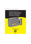
REF : XO 403 + TEL
MANUAL WE5004-2BIS.qxd
20/07/07
15:56
Page 3
2
B
12 mm
4
12 mm
2
4
2
3
3
2
2
1
1
A
E
1
Fig/Abb.1
C
D
F
Fig/Abb 2
E
Fig/Abb 3
Fig/Abb 4
F
1. CARACTÉRISTIQUES / TECHNISCHE
DATEN / CHARACTERISTICS / CARATTERISTICHE /
CARACTERÍSTICAS / PARAMETRY
Serrure électrique ouverture gauche / droite. Déclenchement par impulsion électrique ou clé ou télécommande
Fonctionne sur 8 – 12 V~ continu ou alternatif .
Consommations réduites :
700 mA sous 12 V~
500 mA sous 8 V~
Tension :12-V AC ou DC
Important : Section des fils à raccorder sur les 2 bornes :
• 1 à 25 m : 2 fils de 6/10,
• au-delà 25 m : 2 fils de 1,5 mm2 (sur toute la longueur).
MANUAL WE5004-2BIS.qxd
20/07/07
15:56
Page 4
Elektroschloss, rechts/links verwendbar.
Funktioniert mit 8 – 12 V~ Gleich- oder Alternativstrom.
Reduzierter Verbrauch:
700 mA bei 12 V~
500 mA bei 8 V~
Spannung:12-V AC oder DC
W ichtig:Querschnitt der Anschlussdrähte mit den 2 Verbindungsklemmen verbinden:
• 1 bis 25 m: 2 Drähte Querschnitt 6/10,
• über 25 m: 2 Drähte Querschnitt 1,5 mm2 (auf der ganzen Länge).
Left/right opening function electric lock.
Works on 8 – 12 V ~ continuous or alternating current.
Reduced power consumption:
700 mA at 12 V~
500 mA at 8 V ~
Voltage: 12-V AC or DC
Important: Terminal wire calibre:
• 1-25 metres: 2 x 6/10 wires,
• over 25 metres: 2 x1.5 mm2 wires (the whole length).
Serratura elettrica apertura sinistrorsa / destrorsa.
Funziona su 8 – 12 V~ continua o alternata .
Consumi ridotti:
700 mA a 12 V~
500 mA a 8 V ~
Tensione:12-V AC o DC
Importante: Sezione dei cavi da collegare sui 2 morsetti:
• da 1 a 25 m: 2 cavi da 6/10,
• oltre i 25 m : 2 cavi da 1,5 mm2 (su tutta la lunghezza).
MANUAL WE5004-2BIS.qxd
20/07/07
15:56
Page 5
Cerradura eléctrica abertura izquierda/derecha.
Funciona en 8 - 12 V~continuos o alternativos.
Consumos reducidos:
700 mA en 12 V~
500 mA en 8 V~
Tensión:12-V AC o D.C.
Importante: Sección de los cables que deben conectarse en los 2 terminales:
• 1 a 25 m : 2 cables de 6/10,
• superior a 25 m : 2 cables de 1,5 mm2 (en toda la longitud).
Zamek elektryczny, wersja lewo i prawostronna
Zasilany prądem stałym lub zmiennym 8 – 12 V~.
Niewielki pobór mocy:
700 mA przy 12V~
500 mA przy 8V~
Napięcie: 12-V AC lub DC
Uwaga! Przewody należy podłączyć do dwóch zacisków :
• od 1 do 25 m: 2 przewody 6/10,
• powyżej 25 m: 2 przewody 1,5 mm2 (na całej długości).
2. INSTALLATION / INSTALLATIE / INSTALLAZIONE /
INSTALACIÓN /MONTAŻ
D’origine, la serrure est montée " droite ". Pour la faire devenir " gauche ", il suffit de :
• Pivoter la serrure sur son support métallique.
• Intervertir les 2 caches en caoutchouc pour positionner le trou passe câble en bas . (A)
Ursprünglich wird das Schloss rechts montiert. Um es links zu montieren reicht es:
• das Schloss auf seiner Metallhalterung zu drehen,
• die 2 Kautschukabdeckungen auszutauschen, um die Kabeldurchführung unten positionieren zu können
(A) .
The lock is supplied “right” mounted. To change it to a “left” mounting:
• Swing the lock around on its metal carrier.
• Change over the two rubber covers to position the cable hole downwards (A) .
MANUAL WE5004-2BIS.qxd
20/07/07
15:56
Page 6
D’origine la serratura è montata “destrorsa”. Per farla diventare “sinistrorsa” è sufficiente:
• Ruotare la serratura sul suo supporto metallico.
• Invertire i 2 mascherini in caucciù per posizionare il foro passacavo in basso .(A)
De origen, la cerradura se monta a la “derecha”. Para que pueda montarse a la “izquierda”, basta con:
• Girar sobre su eje la cerradura en su soporte metálico.
• Invertir las 2 tapitas de caucho para colocar el orifico pasa cable abajo . (A)
Zamek jest oryginalnie prawostronny. Aby zmienić wersję na lewostronną należy:
• Obrócić zamek na jego metalowej podstawie.
• Przełożyć gumowe wkładki tak, by otwór na przeprowadzenie kabla znalazł się na dole. (A)
3. FIXATION DE LA SERRURE ÉLECTRIQUE /
BEFESTIGUNG DES ELEKTROSCHLOSSES /
ATTACHMENT OF THE ELECTRIC LOCK / FISSAGGIO DELLA SERRATURA ELETTRICA / FIJACIÓN DE LA CERRADURA ELÉCTRICA
/ MOCOWANIE ZAMKA ELEKTRYCZNEGO
• Déterminer l’emplacement de l’étrier et le trou de passage du cylindre avec le gabarit joint.
Attention, prévoir l’espace suffisant pour le passage de l’antenne du récepteur (B).
• Fixer le support sur le portail à l’aide des 4 vis fournies (C).
• Fixer la serrure électrique sur le support à l’aide des 4 vis (D).
• Positionner le support plastique pour l’antenne autour du cylindre, venir enrouler le câble
antenne à l’intérieur (un seul tour suffit) (E).
• Refermer le boîtier de la serrure électrique à l’aide des 2 vis (F).
• Visser le support plastique et refermer avec le cache plastique pour masquer les vis.
• Den Platz für den Bügel und die Zylinderdurchführung mit der mitgelieferten Schablone bestimmen.
Achtung: Sehen Sie genügend Raum für den Durchgang der Antenne des Empfängers vor (B).
• Die Halterung auf der Tür mit Hilfe der 4 mitgelieferten Schrauben befestigen (C).
• Das Elektroschloss mit Hilfe der 4 Schrauben auf der Halterung befestigen (D).
• Positionieren Sie die Plastikhalterung der Antenne um den Zylinder und rollen das Antennenkabel im
Inneren auf (ein einmaliges Aufrollen reicht aus) (E).
• Das Gehäuse des Elektroschlosses mit Hilfe der 2 Schrauben wieder verschließen (F).
• Schrauben Sie die Plastikhalterung fest und schließen Sie die Plastikabdeckung, um die Schrauben
zu kaschieren.
MANUAL WE5004-2BIS.qxd
20/07/07
15:56
Page 7
• Determine the position of the stirrup and the cylinder hole with the template.
Attention, to plan the space being enough for the passage of the antenna of the receiver (B)
• Using the four screws supplied, fix the carrier to the gate. (C)
• Using the four screws, fix the electric lock to the carrier. (D)
• To position the support blows up for the antenna around the cylinder, to come to roll up the cable
antenna inside (a single tour is enough). (E)
• Close the electric lock housing back up using the two screws (F)
• To screw the plastic support and to close with the plastic mask to mask saw them.
• Determinare il posizionamento della staffa e il foro di passaggio del cilindro con la sagoma acclusa.
Atención, deje espacio suficiente para el paso de la antena del receptor (B)
• Fissare il supporto sul cancello per mezzo delle 4 viti fornite (C)
• Fissare la serratura elettrica sul supporto per mezzo delle 4 viti (D)
• Coloque el soporte de plástico para la antena alrededor del cilindro. Enrolle el cable de la antena
en el interior (basta con una vuelta). (E)
• Richiudere la scatola della serratura elettrica per mezzo delle 2 viti (F)
• Atornille el soporte de plástico y cierre con el cubreplástico para ocultar los tornillos.
• Determinar el emplazamiento de la abrazader a y el agujero de paso del cilindro con el gálibo adjunto.
Attenzione, prevedere uno spazio sufficiente per il passaggio dell’antenna del ricevitore. (B)
• Fijar el soporte en el portal con los 4 tornillos entregados (C)
• Fijar la cerradura eléctrica en el soporte con los 4 tornillos (D)
• Posizionare il supporto di plastica per l’antenna intorno al cilindro, avvolgere il cavo dell’antenna
all’interno (è sufficiente un solo giro). (E)
• Volver a cerrar la caja de la cerradura eléctrica con los 2 tornillos (F)
• Avvitare il supporto di plastica e richiudere con la mascherina di plastica per nascondere
le viti
.
• Przy pomocy załaczonego szablonu okreslic miejsce mocowania zaczepu i otworu na cylinder.
Uwaga! Należy zostawić wystarczające miejsce do przeprowadzenia anteny odbiornika.(B)
• Przymocowac podstawe na bramie przy pomocy 4 srub znajdujacych sie w zestawie. (C)
• Przymocowac zamek elektryczny do podstawy przy pomocy 4 srub. (D)
• Ustawić plastikową podstawę przeznaczoną na antenę wokół cylindra, zwinąć kabel anteny w środku
(wystarczy jeden zwój). (E)
• Zamknac obudowe zamka elektrycznego przy pomocy 2 srub (F)
• Przykręcić plastikową podstawę i zamknąć plastikową pokrywę maskującą śruby
4. FIXATION DE LA GÂCHE FIXE /
BEFESTIGUNG DES FESTSTEHENDEN
TÜRÖFFNERS / FIXING THE KEEPER / FISSAGGIO
DELL’INCONTRO FISSO / FIJACIÓN DEL CERRADERO FIJO
MOCOWANIE NIERUCHOMEGO ZACZEPU (Fig / Abb 3)
• Fixer la gâche fixe à l’aide des 3 vis fournies (E) en respectant la hauteur notée dans le gabarit.
• Den feststehenden Türöffner mit Hilfe der 3 mitgelieferten Schrauben(E) befestigen, dabei die in der
Schablone notierte Höhe berücksichtigen.
• Fix the keeper using the three screws (E) supplied according to the height stipulated in the template.
• Fissare l’incontro per mezzo delle 3 viti fornite (E) rispettando l’altezza annotata nella sagoma.
MANUAL WE5004-2BIS.qxd
20/07/07
15:56
Page 8
• Fijar el cerradero fijo con los 3 tornillos entregados(E) respetando la altura que está anotada en el gálibo.
• Przymocować nieruchomy zaczep przy pomocy 3 śrub znajdujących się w zestawie (E)
przestrzegając wysokości zaznaczonej w szablonie.
5. CÂBLAGE ÉLECTRIQUE /
ELEKTROVERDRAHTUNG / ELECTRICAL CONNECTIONS /
CABLAGGIO ELETTRICO / CABLEADO ELÉCTRICO /
OKABLOWANIE ELEKTRYCZNE (Fig / Abb 1)
• Passer les câbles par le trou " passe câble "(A).
• Dévisser légèrement les 2 vis 1 .
• Coincer le premier fil entre les 2 lamelles.
• Répéter l’opération pour le deuxième fil (aucune polarité à respecter).
Remarque importante :
Cette serrure ne peut pas être utilisée sur un portail s’ouvrant vers l’extérieur.
Distance à respecter entre la gâche et la serrure de 9 mm environ (côte F , figure 4).
En cas de panne d’électricité, la clé peut toujours être utilisée et il n’y a donc aucun problème pour
rentrer chez soi.
Si vous voulez tester ou essayer votre serrure alors qu’elle n’est pas installée, vous devez absolument simuler la présence de la gâche en appuyant sur le penne de mémorisation ( 2, Fig. 1), afin
d’activer la mémoire mécanique.
MANUAL WE5004-2BIS.qxd
20/07/07
15:56
Page 9
• Die Drähte durch die Durchführungen führen(A).
• Die 2 Schrauben nur leicht losschrauben 1 .
• Den ersten Draht zwischen den 2 Lamellen einklemmen.
• Für den zweiten Draht genauso vorgehen (es ist keine Polarität zu berücksichtigen).
W ichtige Anmerkung:
Dieses Schloss kann nicht auf einem Tor benutzt werden, das sich nach außen öffnet.
Zwischen dem Türöffner und dem Schloss muss ein Abstand von etwa 9 mm respektiert werden
(Seite F, Abb. 4).
Im Fall einer Panne, kann immer noch der Schlüssel zum Öffnen genutzt werden, so haben Sie
immer Zugang und bleiben niemals ausgeschlossen.
Wenn Sie Ihr Schloss vor der Installation testen möchten, müssen Sie unbedingt den Türöffner
simulieren, indem Sie auf die speichernde Schwungfeder drücken ( 2 , Abb. 1), um den mechanischen Speicher zu aktivieren.
• Pass the cables through the correct hole (A).
• Loosen the two screws 1 .
• Fix the first wire between the two small plates.
• Do the same with the second wire (ignore the polarity).
Important:
This type of lock cannot be used on outward-opening gates.
Leave a space of about 9 millimetres between the keeper and the lock (side F, figure 4).
During a power cut, the key can always be used so there is never any problem getting back in.
If you want to test your lock before it is installed, the presence of the keeper must always be simulated by pressing on the memorisation flap ( 2 , Fig. 1) to activate the mechanical memory.
• Passare i cavi nel foro "passacavi"(A) .
• Svitare leggermente le 2 viti 1 .
• Bloccare il primo cavo tra le 2 lamelle.
• Ripetere l’operazione per il secondo cavo (nessuna polarità da rispettare).
Osservazione importante:
Questa serratura non è utilizzabile su di un cancello ad apertura verso l’esterno.
Distanza da rispettare tra l’incontro e la serratura 9 mm circa (lato F, figura 4).
In caso di mancanza di elettricità la chiave può sempre essere utilizzata e non c’è problema per
poter rientrare.
MANUAL WE5004-2BIS.qxd
20/07/07
15:56
Page 10
Se desiderate testare o provare la serratura prima di installarla,è imperativamente necessario
simulare la presenza dell’incontro sulla stanghetta di memorizzazione ( 2 , Fig. 1), al fine di attivare la memoria meccanica.
• Pasar los cables por el agujero “pasa cable”(A).
• Destornillar ligeramente los 2 tornillos 1 .
• Sujetar el primer cable entre las 2 láminas.
• Repetir la operación para el segundo cable (no debe respetarse ninguna polaridad).
Przeprowadzić przewody przez otwór przeznaczony do tego celu (A).
• Poluzować obydwie śruby.
• Zablokować pierwszy przewód między 2 płytkami.
• Powtórzyć czynności przy drugim przewodzie (nie trzeba przestrzegać biegunowości).
2
Ważne!
Zamek ten nie może być stosowany w bramach otwierających się na zewnątrz.
Między nieruchomym zaczepem a zamkiem należy zachować odstęp około 9 mm (wymiar F,
rysunek 4).
W przypadku przerwy w dostawie prądu można użyć klucza, by bez problemu dostać się do domu.
Aby przetestować lub wypróbować zamek, gdy nie jest jeszcze zamontowany, należy koniecznie
zasymulować obecność zaczepu poprzez wciśnięcie trzpienia pamięci ( , ryc. 1) w celu aktywowania
pamięci mechanicznej.
2
MANUAL WE5004-2BIS.qxd
20/07/07
15:56
Page 1
Nie należy umieszczać zużytych baterii lub zepsutych urządzeń w odpadach
domowych. Substancje niebezpieczne, które mogą się w nich znajdować, mogą być
szkodliwe dla zdrowia. Należy przekazać urządzenie dystrybutorowi lub umieścić w
pojemnikach do zbiórki selektywnej zapewnianej przez gminę.