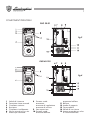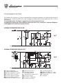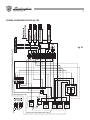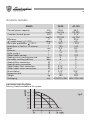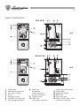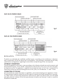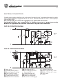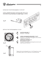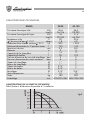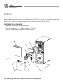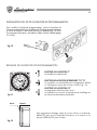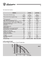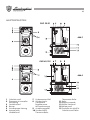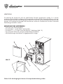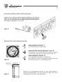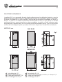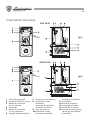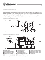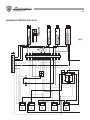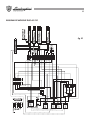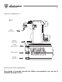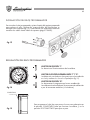
1
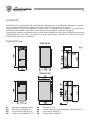
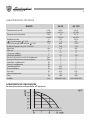
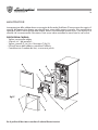
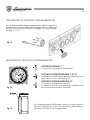
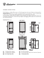
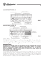
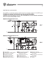
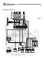
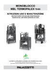
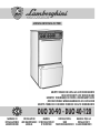
1
AZIENDA CERTIFICATA ISO 9001
GRUPPI TERMICI IN GHISA AD ALTO RENDIMENTO
HIGH EFFICIENCY CAST IRON BOILERS
GROUPES THERMIQUES EN FONTE A RENDEMENT ELEVE
HOCHLEISTUNGS-WÄRMEAGGREGATE AUS GUSSEISEN
GRUPOS TÉRMICOS DE HIERRO FUNDIDO DE ALTO RENDIMIENTO
DUO 30-90 - DUO 40-120
MANUAL PARA LA
INSTALLATIONSMANUEL
INSTALLATION
MANUALE DI
INSTALACIÓN Y
UND
INSTALLAZIONE E AND MAINTENANCE D'INSTALLATION ET
D'ENTRETIEN WARTUNGSHANDBUCH EL MANTENIMIENTO
MANUAL
MANUTENZIONE
2
ITALIANO
4
3
Leggere attentamente le istruzioni ed avvertenze contenute sul presente libretto in quanto forniscono importanti indicazioni riguardanti la sicurezza d’installazione, d’uso e di
manutenzione. Conservare con cura questo libretto per ogni ulteriore consultazione.
L’installazione deve essere effetuata da personale qualificato che sarà responsabile del
rispetto delle norme di sicurezza vigenti.
16
ENGLISH
Read carefully all warnings and instructions contained in this manual as they give
important safety instructions regarding installation, use and maintenance. Keep this
manual for future reference. Installation must be carried out by qualified personnel who
will be responsible for respecting existing safety regulations.
FRANCAIS
28
Lire attentivement le mode d’emploi et les instructions du présent livret car ils fournissent
des indications de l’emploi et de la manutention. Conserver avec soin ce livret pour
ultérieures consultations. L’installation doit être effectuèe par un personnel qualifié qui
sera responsable de respecter les normes de sécurité en viguer.
DEUTSCH
40
Bitte lesen Sie die Anleitungen und Hinweise in dem vorliegenden Handbuch aufmerksam durch. Sie enthalten wichtige Informationen bezüglich Installation, Gebrauch und
Wartung. Bewahren Sie dieses Handbuch zum späteren Nachschlagen sorgfältig auf.
Die Installation ist von qualifiziertem Fachpersonal unter Berücksichtigung der geltenden Sicherheitsvorschriften durchzuführen.
ESPANOL
52
Leer atentamente las instrucciones y las advertencias que contiene el presente folleto ya
que dan indicaciones importantes relativas a la seguridad de la instalación, al uso y al
mantenimiento.
Conservar con cuidado este folleto para cualquier ulterior consulta. La instalación debe
ser efectuada por personal cualificado que tendrá la responsabilidad de respetar las
normas de seguridad vigentes.
4
INDICE
PAGINA
GENERALITÀ
5
DIMENSIONI mm.
5
CARATTERISTICHE TECNICHE
6
COMPONENTI PRINCIPALI
7
INSTALLAZIONE
8
COLLEGAMENTI ELETTRICI
9
CONTROLLI E VERIFICHE
12
ACCENSIONE - SPEGNIMENTO
12
CIRCUITO IDRAULICO
13
REGOLAZIONE BRUCIATORE
13
MANUTENZIONE
14
ISTALLAZIONE KIT OROLOGIO PROGRAMMATORE
15
REGOLAZIONE OROLOGIO PROGRAMMATORE
15
Complimenti...
... per l’ottima scelta !
La LAMBORGHINI garantisce non solo la qualità del prodotto, ma anche l’efficienza della sua
rete di assistenza tecnica.
Leggere attentamente le istruzioni ed avvertenze contenute sul presente libretto in quanto forniscono importanti indicazioni riguardanti la sicurezza d’installazione, d’uso e di manutenzione.
Conservare con cura questo libretto per ogni ulteriore consultazione.
L’installazione deve essere effettuata da personale qualificato che sarà responsabile del rispetto delle
norme di sicurezza vigenti.
5
GENERALITÀ
La caldaia DUO è un generatore di calore ad alto rendimento per il riscaldamento domestico e la produzione di acqua calda sanitaria, adatta a funzionare con bruciatori di gas o di gasolio.
Il corpo caldaia e in ghisa, assemblati con tiranti e biconi. Il profilo è stato curato con una ripartizione
delle alette consentendo un alta prestazione termica con conseguente risparmio energetico.
L’estetica ed il completo isolamento sono assicurati da un elegante cruscotto, da un mantello verniciato ed
assemblato a pressione, da un rivestimento in lana di vetro di grosso spessore che riduce al minimo le
dispersioni di calore verso l’ambiente.
DIMENSIONI mm.
DUO 30-90
fig.1
DUO 40-120
a1
a2
a3
a4
Mandata riscaldamento Ø 1”
Ritorno riscaldamento Ø 1”
Uscita acqua calda Ø 3/4”
Entrata acqua fredda Ø 3/4”
a5
a6
a7
a8
Ricircolo Ø 3/4”
Attacco valvola di sicurezza bollitore (eventuale) Ø 1/2”
Uscita acqua calda Ø 1”
Entrata acqua fredda Ø 1”
6
CARATTERISTICHE TECNICHE
DUO
Potenza termica utile
Potenza termica focolare
Rendimento utile
P circuito acqua T 10OC
Produzione acqua calda sanitaria T 30OC
Prelievo di punta nei primi 10 minuti
Ripristino
Elementi
Contenuto caldaia
Contenuto bollitore
Pressione di esercizio circuito di riscaldamento
Pressione di esercizio circuito sanitario
Mandata riscaldamento
Ritorno riscaldamento
Mandata bollitore
Ritorno bollitore
Ricircolo
Vaso di espansione
Peso
Imballo
kW
kcal/h
kW
kcal/h
%
mbar
l/h
l
min
no
l
l
bar
bar
Ø
Ø
Ø
Ø
Ø
l
kg
mm.
30-90
40-120
30,6
26.316
34
29.240
90
1,8
800
130
9,5
3
14
90
3
6
1”
1”
3/4”
3/4”
3/4”
10
180
600x900x1560
46,5
39.990
51,4
44.204
90,4
4,2
1.200
145
8,5
4
17
120
3
6
1”
1”
1”
1”
3/4”
10
285
660x1085x1560
CARATTERISTICHE CIRCOLATORE
Portata/prevalenza disponibile all’impianto
fig.2
7
COMPONENTI PRINCIPALI
DUO 30-90
fig.3
DUO 40-120
fig.4
1
2
3
4
5
6
7
Valvola di sicurezza
Termostato riarmo manuale
Circolatore sanitario
Bruciatore
Circolatore riscaldamento
Valvola automatica sfogo aria
Attacco per idrometro
8
Pozzetto sonde:
termometro
termostato di regolazione
termostato di minima
9 Vaso espansione
10 Pozzetto sonde:
termostato bollitore
11
12
13
14
15
termometro bollitore
Bollitore
Anodo di magnesio
Corpo caldaia
Valvola di non ritorno
Attacco eventuale per valvola sicurezza bollitore
8
CRUSCOTTO DUO 30-90
fig.5
CRUSCOTTO DUO 40-120
fig.6
INSTALLAZIONE
L’installazione della caldaia deve essere effettuata solo da Personale Qualificato, seguendo le indicazioni
del Costruttore ed in ottemperanza a tutte le leggi e disposizioni che regalano la materia. Si raccomanda
in particolar modo il rispetto delle norme in materia di sicurezza e di quelle che regolano la costruzione e
l’ubicazionedelle canne fumarie.
ALLACCIAMENTO IDRAULICO
Eseguire l’allacciamento idraulico dell’apparecchio rispettando le indicazioni poste in prossimità di ogni
attacco e quelle riportate nella figura 1 di questo libretto. L’allacciamento deve essere fatto in modo che i
tubi siano liberi da tensioni. L’apparecchio è fornito di un vaso d’espansione. A tal proposito si ricorda che
la pressione del caricamento dell’impianto, deve essere compresa tra 1,2 e 1,5 bar.
COLLEGAMENTO ALLA CANNA FUMARIA
Si raccomanda di collegare la caldaia ad una buona canna fumaria, costruita nel rispetto delle norme
vigenti. Il condotto tra caldaia e canna fumaria deve essere di materiale adatto allo scopo, ovvero resistente alla temperatura ed alla corrosione. Nei punti di giunzione si raccomanda di curare la tenuta e di
isolare termicamente tutto il condotto tra caldaia e camino al fine di evitare la formazione della condensa.
9
COLLEGAMENTI ELETTRICI
Consigliamo di interporre tra la rete e l’apparecchio un interruttore bipolare, con apertura dei contatti di
almeno 3 mm, munito di fusibili di 5 A max. Collegare la caldaia ad una linea elettrica di 230 V - 50 Hz
fase/neutro.
Si raccomanda inoltre di collegare l’apparecchio ad un buon impianto di terra.
La Lamborghini declina ogni responsabiltà per danni a persone o cose, causati per il mancato collegamento dell’apparecchio ad un buon impianto di terra.
SCHEMA DI PRINCIPIO DUO 30-90
fig.7
SCHEMA DI PRINCIPIO DUO 40-120
fig.8
IG Interruttore generale
E/I Selettore ESTATE/INVERNO
OR Orologio programmatore (eventuale)
CO Contatto orologio (eventuale)
TA Termostato ambiente (eventuale)
TB Termostato bollitore 0-65OC
TR1 Termostato di regolazione 0-80OC
TR2 Termostato limite 85OC
TM Termostato di minima
anticondensa 0-45OC
TS Termostato di sicurezza 100OC
CiB Circolatore bollitore
CiR Circolatore riscaldamento
SB Spia blocco bruciatore
SF Spia di funzionamento
BR1 Bobina relè 230Vac a 1 contatto
BR2 Bobina relè 230Vac a 1 contatto
CB Contatto relè
B Bruciatore
10
SCHEMA DI MONTAGGIO DUO 30-90
fig.9
11
SCHEMA DI MONTAGGIO DUO 40-120
fig.10
12
CONTROLLI E VERIFICHE
PRIMA DELL’ACCENSIONE INIZIALE
Prima dell’accensione iniziale, e buona norma controllare che:
-
L’impianto sia riempito alla giusta pressione e sfiatato.
Non vi siano perdite d’acqua o di combustibile.
L’alimentazione elettrica sia corretta.
Tutto il condotto fumi sia stato eseguito correttamente e che non sia vicino o attraversi parti infiammabili.
Non vi siano sostanze infiammabili nelle vicinanze dell’apparecchio.
II bruciatore sia proporzionato alla potenza di caldaia.
Le valvole d’intercettazione acqua siano aperte.
Verifica della posizione e taratura dei termostati.
Verifica della portata di acqua sanitaria.
DOPO L’ACCENSIONE INIZIALE
Dopo la prima accensione e buona norma controllare che:
-
Che il bruciatore funzioni correttamente. Questo controllo va fatto con gli appositi strumenti.
I termostati funzionino correttamente.
L’acqua circoli nell’impianto.
L’evacuazione dei fumi avvenga completamente attraverso il camino.
ACCENSIONE - SPEGNIMENTO
ACCENSIONE INIZIALE
Effettuati i controlli preliminari, si può procedere con le seguenti manovre di accensione:
- Aprire la valvola d’intercettazione combustibile (eventuale).
- Regolare il termostato caldaia al valore desiderato.
- Chiudere l’interruttore a monte della caldaia e l’interruttore Estate/Inverno posto sul pannello comandi.
SPEGNIMENTO
Per brevi periodi di sosta e sufficiente agire sull’interruttore acceso/spento posto sul pannello comandi.
Per lunghe soste durante il periodo invernale, onde evitare danni causati dal gelo, e necessario introdurre
l’apposito antigelo nell’impianto o svuotare quest’ultimo completamente.
13
CIRCUITO IDRAULICO
fig.11
REGOLAZIONE DEL BRUCIATORE
Per la regolazione del bruciatore consultare i relativi libretti inseriti nell’imballo del
gruppo termico.
14
MANUTENZIONE
La manutenzione della caldaia deve essere eseguita da Personale Qualificato. È buona norma far eseguire il
controllo dell’apparecchio almeno una volta all’anno, prima della stagione invernale. Tale controllo deve
riguardare, oltre lo stato di pulizia della caldaia, anche il funzionamento corretto di tutti i suoi dispositivi di
controllo e di sicurezza nonchè il bruciatore. Deve essere inoltre controllato lo stato di tutto lo scarico fumi.
PULIZIA DELLA CALDAIA
-
Togliere corrente alla caldaia.
Svitare le viti 1 del pannello 2.
Togliere i pannelli 2,3,4,5,6 e il bruciatore 7 (fig.12).
Pulire all’interno della caldaia e controllare il bollitore.
Controllare tutto il condotto dei fumi, se necessario pulirlo.
fig.12
Per la pulizia del bruciatore consultare il relativo libretto istruzioni
15
ISTALLAZIONE KIT OROLOGIO PROGRAMMATORE
Per l’installazione dell’orologio programmatore, togliere il tappo foro
orologio ed utilizzare le quattro viti di fissaggio fornite in dotazione
(fig.13). Per le connessioni elettriche, collegare i cavi come da schema (pag. 9-10-11).
fig.13
REGOLAZIONE OROLOGIO PROGRAMMATORE
SELETTORE IN POSIZIONE “I”
Si disattiva il funzionamento della caldaia
SELETTORE IN POSIZIONE INTERMEDIA “I” ED “O”
La caldaia è comandata dal programma impostato sul l’orologio tramite i cursori a levetta (fig.15).
SELETTORE IN POSIZIONE INTERMEDIA “O”
fig.14
Viene escluso il programma impostato.
La caldaia viene asservita al termostato riscaldamento oppure al termostato ambiente (eventuale).
fig.15
Per la programmazione dell’orologio mettere il cursore a levetta in
posizione INSERITO per avere il funzionamento della caldaia, in
posizione DISINSERITO per lo spegnimento
16
INDEX
PAGE
GENERAL INSTRUCTIONS
17
DIMENSIONS mm
17
TECHNICAL FEATURES
18
MAIN COMPONENTS
19
INSTALLATION
20
ELECTRICAL CONNECTIONS
21
CONTROL TESTS
24
SWITCHING ON - SWITCHING OFF
24
HYDRAULIC CIRCUIT
25
BURNER ADJUSTMENT
25
MAINTENANCE
26
INSTALLING THE PROGRAMMING CLOCK KIT
27
SETTING THE PROGRAMMING CLOCK
27
Congratulations....
...on an excellent choice!
LAMBORGHINI guarantees his products quality , and also the efficiency of his technical after-sale
service network.
FOR ANY NECESSITY CALL THE NEAREST LAMBORGHINI AGENCY.
Read carefully all warnings and instructions contained in this manual as they give important safety instructions
regarding installation, use and maintenance. Keep this manual for future reference. Installation must be
carried out by qualified personnel who will be responsible for respecting existing safety regulations.
17
GENERAL INSTRUCTIONS
The DUO boiler is a highly efficient gas or oil fired heat generator that meets all domestic heating and hot
water requirements.
The boiler shell is made of cast iron and is assembled with boiler studs and bicones. The fins are distributed
in such a way as to assure high heating performance with consequent fuel conservation.
The final aesthetic image and total insulation are guaranteed by the elegant control panel, the pressure
assembled enamelled chassis, and a thick layer of glass wool lagging which reduces to a minimum heat
loss into the environment.
DIMENSIONS mm.
DUO 30-90
fig.1
DUO 40-120
a1
a2
a3
a4
1” Ø heating flow tapping
1” Ø heating return tapping
3/4” Ø hot water outlet
3/4” Ø cold water inlet
a5
a6
a7
a8
3/4” Ø re-circulation
1/2” Ø water heater safety valve connection (if present)
1” Ø hot water outlet
1” Ø cold water inlet
18
TECHNICAL FEATURES
DUO
Thermal power capacity
Chamber thermal power
Efficiency
P water circuit T 10°C
Hot water production T 30°C
Peak draw in the first 10 minutes
Reset
Elements
Boiler content
Water heater content
Heating circuit working pressure
Hot water working pressure
Heating flow connection
Heating return connection
Water heater flow connection
Water heater return connection
Re-circulation
Expansion tank
Weight
Packaging
30-90
40-120
30,6
46,5
kW
26.316
39.990
kcal/h
34
51,4
kW
29.240
44.204
kcal/h
90
90,4
%
1,8
4,2
mbars
800
1.200
l/h
130
145
l
9,5
8,5
min
no
3
4
14
17
l
90
120
l
3
3
bars
bars
6
6
Ø
1”
1”
Ø
1”
1”
Ø
3/4”
1”
3/4”
1”
Ø
3/4”
3/4”
Ø
l
10
10
kg
180
285
mm. 600x900x1560 660x1085x1560
CIRCULATOR SPECIFICATIONS
Delivery/head available to the system.
fig.2
19
MAIN COMPONENTS
DUO 30-90
fig.3
DUO 40-120
fig.4
1
2
3
4
5
6
7
Safety valve
Manual reset thermostat
Hot water circulator
Burner
Heating circulator
Automatic air purge valve
Water gauge connection
8
Probe trap:
thermometer
control thermostat
minimum thermostat
9 Expansion tank
10 Probe trap:
water heater thermostat
11
12
13
14
15
water heater thermometer
Water heater
Magnesium anode
Boiler shell
Non-return valve
Water heater safety valve
connection (if present)
20
DUO 30-90 CONTROL PANEL
fig.5
DUO 40-120 CONTROL PANEL
fig.6
INSTALLATION
The boiler must absolutely be installed by qualified experts, according to the manufacturer’s indications
and in compliance with all the relative laws and regulations. We particularly recommend that all safety
specifications and regulations regarding the construction and positioning of flues are respected.
HYDRAULIC CONNECTION
Connect the appliance to the water system according to the indications placed near each connection and
those outlined in figure 1 of this manual. Connection must be carried in such a way as to ensure the pipes
are free from tension. The appliance is supplied with an expansion tank. As far as this is concerned, we
would like to remind you that the loading pressure of the system, must fall between 1.2 and 1.5 bars.
CONNECTION TO THE FLUE
We recommend you connect the boiler to a good flue, constructed according to the regulations in force.
The pipe between the boiler and the flue must be made of a material specifically designed for this purpose,
or in other words, resistant to high temperatures and corrosion. Make sure that any joints are well sealed
and apply thermal insulation to the entire pipe between the boiler and chimney in order to avoid the
formation of condensate.
21
ELECTRICAL CONNECTIONS
We advise you to place a bipolar switch with contacts having at least a 3 mm aperture between the supply
mains and the appliance, equipped with max. 5 A fuses. Connect the boiler to a 230 V - 50 Hz phase/
neutral supply mains.
We recommend you connect the appliance to a good earth connection.
Lamborghini declines any responsibility for damage to persons or property occurring
because the appliance has not been connected to a good earth connection.
DUO 30-90 PRINCIPLE DIAGRAM
fig.7
DUO 40-120 PRINCIPLE DIAGRAM
fig.8
IG Main switch
E/I SUMMER/WINTER selector
OR Programming timer (if existing)
CO Timer contact (if existing)
TA Room thermostat (if existing)
TB Cylinder thermostat 0-65°C
TR1 Adjustment thermostat 0-80°C
TR2 Limit thermostat 0-85°C
TM Anti-condensation minimum
thermostat 0-45°C
TS Safety thermostat 100°C
CiB Cylinder circulating pump
CiR Heating circulating pump
SB Burner lock-out warning light
SF Operation warning light
BR1 Relay coil 230 Vac with 1 contact
BR2 Relay coil 230 Vac with 1 contact
CB Relay contact
B Burner
22
DUO 30-90 ASSEMBLY DIAGRAM
fig.9
23
DUO 40-120 ASSEMBLY DIAGRAM
fig.10
24
CONTROL TESTS
BEFORE THE FIRST IGNITION
Before the first ignition, we recommend you check the following:
-
The system has been filled to the right pressure and has been purged.
There is no leakage of water or fuel.
The electrical supply is correct.
The entire flue system has been carried out properly and that it is not near inflammable parts.
There are no inflammable substances near the appliance.
The burner is proportioned to the boiler capacity.
The water interception valves are opened.
Check the position and calibration of the thermostats.
Check the delivery of the hot water.
AFTER THE FIRST IGNITION
After the first ignition, we recommend you make sure that:
-
The burner works correctly. This control must be carried out using the correct instruments.
The thermostats work correctly.
The water circulates around the system.
All the smoke is completely evacuated through the flue.
SWITCHING ON - SWITCHING OFF
FIRST IGNITION
Once the preliminary controls have been carried out, make the ignition manoeuvres as follows:
- Open the fuel interception valve (if present).
- Set the boiler thermostat to the desired value.
- Shut off the switch upstream the boiler and the Summer/Winter switch placed on the control panel
SWITCHING OFF
When switching off for short periods of time, act on the on/off switch placed on the control panel.
When switching off for long periods of time during winter, so as to avoid damage caused by freezing
temperatures, it is necessary to introduce a suitable anti-freeze into the system or completely drain the
system.
25
HYDRAULIC CIRCUIT
fig.11
Heating
flow
Heating
return
Hot water
outlet
Re-circulation
Cold water
inlet
BURNER ADJUSTMENT
For the burner adjustment, read the related manuals included in the packaging of the
boiler.
26
MAINTENANCE
Any maintenance must be carried out on the boiler by qualified experts. We advise you to check the
appliance at least once a year, before winter season. The check up must not only include making sure that
the boiler is clean, but must also verify the condition of all the control and safety devices, and the burner.
The condition of the entire flue system must also be checked.
CLEANING THE BOILER
-
Disconnect the boiler from the mains supply.
Remove the screws 1 from the panel 2.
Remove the panels 2, 3, 4, 5, 6 and the burner 7 (fig.12).
Clean the inside of the boiler and check the water heater.
Check the entire flue, and if necessary, clean it.
fig.12
For burner cleaning read the related instruction manual.
27
INSTALLING THE PROGRAMMING CLOCK KIT
Install the programming clock by removing the clock cover on the
control panel and fix using the four screws supplied (fig. 13). Connect
to the electricity supply according to the diagram (pages 21-22-23).
fig.13
SETTING THE PROGRAMMING CLOCK
SELECTOR IN POSITION “I”
The boiler is switched off.
SELECTOR IN THE INTERMEDIATE POSITION BETWEEN “I” AND “O”
The boiler runs according to the program set on the clock
using the cursors (fig. 15).
SELECTOR IN POSITION “0”
The set program is cut out.
The boiler is controlled by the heating thermostat or by the
room thermostat (if present).
fig.14
ON
OFF
Program the timer by placing the cursor in the ON position to switch
on the boiler, place in the OFF position to switch off the boiler.
fig.15
28
INDEX
PAGE
GENERALITES
29
DIMENSIONS en mm.
29
CARACTERISTIQUES TECHNIQUES
30
ELEMENTS PRINCIPAUX
31
INSTALLATION
32
CONNEXIONS ELECTRIQUES
33
CONTROLES ET VERIFICATIONS
36
ALLUMAGE - ARRET
36
CIRCUIT HYDRAULIQUE
37
REGLAGE DU BRULEUR
37
ENTRETIEN
38
INSTALLATION DU KIT DE L’HORLOGE DE PROGRAMMATION
39
REGLAGE DE L’HORLOGE DE PROGRAMMATION
39
Felicitations ...
... pour l’excellent choix !
LAMBORGHINI garantit non seulement la qualité du produit, mais aussi l’efficacité de son réseau
de service Après-Vente.
EN CAS DE BESOIN, S’ADRESSER A L’AGENCE LAMBORGHINI LA PLUS PROCHE.
Lire attentivement les instructions et les avertissements reportés dans ce livret car ils fournissent des indications
importantes sur la sécurité d’installation, d’utilisation et d’entretien.
Bien conserver ce livret pour toute consultation ultérieure.
L’installation doit être effectuée par un personnel professionnellement qualifié qui sera responsable du
respect des normes de sécurité en vigueur.
29
GENERALITES
La chaudière DUO est un générateur de chaleur à haut rendement pour le chauffage domestique et la
production d’eau chaude sanitaire, indiqué pour fonctionner avec des brûleurs à gaz ou à fioul domestique.
Le corps de la chaudière est en fonte, assemblé avec des tirants et des bicônes. Le profil a été soigné avec
une répartition des ailettes permettant une haute performance thermique et, par conséquent, une économie
d’énergie. Un tableau de commande élégant, un habillage verni et assemblé par pression et un revêtement
en laine de verre très épais qui réduit au minimum les déperditions de chaleur dans la pièce garantissent
l’esthétique et toute l’isolation thermique.
DIMENSIONS en mm.
DUO 30-90
fig.1
DUO 40-120
a1
a2
a3
a4
Départ du chauffage Ø 1”
Retour du chauffage Ø 1”
Sortie de l’eau chaude Ø 3/4”
Entrée de l’eau froide Ø 3/4”
a5
a6
a7
a8
Recyclage Ø 3/4”
Raccordement soupape de sûreté du ballon (facultatif) Ø 1/2”
Sortie de l’eau chaude Ø 1”
Entrée de l’eau froide Ø 1”
30
CARACTERISTIQUES TECHNIQUES
DUO
30-90
40-120
30,6
46,5
kW
26.316
39.990
kcal/h
Puissance thermique du foyer
kW
34
51,4
29.240
44.204
kcal/h
90
90,4
Rendement utile
%
1,8
4,2
P du circuit d’eau T 10°C
mbars
800
1.200
Production d’eau chaude sanitaire T 30°C
l/h
Prélèvement de pointe dans les 10 premières minutes
130
145
l
Remise en service
9,5
8,5
min
Eléments
no
3
4
14
17
l
Capacité de la chaudière
90
120
Capacité du ballon
l
3
3
Pression d’exercice du circuit de chauffage bars
bars
Pression d’exercice du circuit sanitaire
6
6
Ø
Départ du chauffage
1”
1”
Retour du chauffage
Ø
1”
1”
Ø
Départ du ballon
3/4”
1”
3/4”
1”
Ø
Retour du ballon
3/4”
3/4”
Ø
Recyclage
Vase d’expansion
l
10
10
kg
Poids
180
285
mm. 600x900x1560 660x1085x1560
Emballage
Puissance thermique utile
CARACTERISTIQUES DE LA POMPE DE CIRCULATION
Débit/hauteur d’élévation disponible à l’installation
fig.2
31
ELEMENTS PRINCIPAUX
DUO 30-90
fig.3
DUO 40-120
fig.4
1
2
3
4
5
6
Soupape de sûreté
Thermostat de réarmement manuel
Pompe de circulation du
circuit sanitaire
Brûleur
Pompe de circulation du chauffage
Soupape automatique de
purge d’air
7
Raccordement pour
l’hydromètre
8 Regard de visite des sondes:
thermomètre
thermostat de réglage
thermostat de minimum
9 Vase d’expansion
10 Regard de visite des sondes:
11
12
13
14
15
thermostat du ballon
thermomètre du ballon
Ballon
Anode de magnésium
Corps de la chaudière
Soupape de non retour
Raccordement éventuel pour la
soupape de sûreté du ballon
32
TABLEAU DE COMMANDE DUO 30-90
fig.5
TABLEAU DE COMMANDE DUO 40-120
fig.6
INSTALLATION
L’installation de la chaudière ne doit être effectuée que par un personnel professionnellement qualifié,
selon les instructions du fabricant et conformément à toutes les normes et les dispositions qui règlent le
secteur. Nous recommandons en particulier de respecter les normes en matière de sécurité et celles qui
règlent la construction et l’installation des conduits de fumée.
BRANCHEMENT HYDRAULIQUE
Effectuer le branchement hydraulique de l’appareil en respectant les indications qui se trouvent près de chaque
raccordement et celles reportées sur la figure 1 de ce livret. Le branchement doit être effectué de façon à ce que
tous les tuyaux soient libres de contraintes. L’appareil est équipé d’un vase d’expansion. Nous rappelons, à ce
propos, que la pression du remplissage de l’installation doit être comprise entre 1,2 et 1,5 bars.
RACCORDEMENT AU CONDUIT DE FUMEE
Nous recommandons de raccorder la chaudière à un bon conduit de fumée, construit conformément aux
normes en vigueur. Le conduit entre la chaudière et le conduit de fumée doit être d’un matériel prévu à cet
effet, c’est-à-dire résistant à la température et à la corrosion. Aux points de jonction, nous recommandons,
de soigner l’étanchéité et d’isoler thermiquement tout le conduit entre la chaudière et la cheminée afin
d’éviter la formation d’eau de condensation.
33
CONNEXIONS ELECTRIQUES
Nous conseillons d’interposer un interrupteur bipolaire entre le réseau et l’appareil, avec une ouverture des
contacts d’au moins 3 mm, pourvu de fusibles de 5A max. Brancher la chaudière sur une ligne électrique
de 230 V - 50 Hz phase/neutre.
Nous recommandons en outre de brancher l’appareil sur une bonne installation de mise à la terre. Lamborghini
décline toute responsabilité pour des dommages causés aux personnes ou aux choses, dus au branchement de
l’appareil à une mauvaise installation de mise à la terre.
SCHEMA DE PRINCIPE DUO 30-90
fig.7
SCHEMA DE PRINCIPE DUO 40-120
fig.8
IG Interrupteur général
E/I Sélecteur ETE / HIVER
OR Horloge de programmation
(facultatif)
CO Compteur de l’horloge (facultatif)
TA Thermostat d’ambiance (facultatif)
TB Thermostat du ballon 0-65°C
TR1 Thermostat de réglage 0-80°C
TR2 Thermostat limite 0-85°C
TM Thermostat de témperature minimale
anticondensation 0-45°C
TS Thermostat de sécurité 100°C
CiB Pompe de circulation du ballon
CiR Pompe de circulation du chauffage
SB Lampe témoin d’arrêt du brûleur
SF Lampe témoin de fonctionnement
BR1 Bobine relais 230 Vac à 1 contact
BR2 Bobine relais 230 Vac à 1 contact
CB Contact du relais
B Brûleur
34
SCHEMA DE MONTAGE DUO 30-90
fig.9
35
SCHEMA DE MONTAGE DUO 40-120
fig.10
36
CONTROLES ET VERIFICATIONS
AVANT L’ALLUMAGE INITIAL
Avant l’allumage initial, il est de règle de vérifier:
-
Que l’installation soit remplie à la juste pression et soit purgée.
Qu’il n’y ait pas de pertes d’eau ou de combustible.
Que l’alimentation électrique soit correcte.
Que tout le conduit des fumées ait été effectué correctement et qu’il ne soit pas situé à proximité de
parties inflammables ou qu’il les traverse.
Qu’il n’y ait pas de substances inflammables à proximité de l’appareil.
Que le brûleur soit proportionnel à la puissance de la chaudière.
Que les vannes d’interception d’eau soient ouvertes.
La position et le réglage des thermostats.
Le débit d’eau du circuit sanitaire.
APRES L’ALLUMAGE INITIAL
Après le premier allumage, il est de règle de vérifier que:
-
Le brûleur fonctionne correctement. Ce contrôle doit être effectué avec les instruments prévus à cet effet.
Les thermostats fonctionnent correctement.
L’eau circule dans l’installation.
L‘évacuation des fumées s’effectue complètement par la cheminée.
ALLUMAGE - ARRET
ALLUMAGE INITIAL
Lorsque les vérifications préliminaires ont été faites, on peut alors effectuer les manoeuvres d’allumage
suivantes:
- Ouvrir la vanne d’interception du combustible (facultative).
- Régler le thermostat de la chaudière à la valeur souhaitée.
- Débrancher l’interrupteur en amont de la chaudière et le sélecteur Eté/ Hiver placé sur le tableau de
commande.
ARRET
Pour de brèves périodes d’arrêts, il suffit d’intervenir sur l’interrupteur allumage/arrêt placé sur le tableau
de commande.
Pour de longues périodes d’arrêt en hiver, il faut introduire l’antigel approprié dans l’installation ou la
vidanger complètement, pour éviter les dommages provoqués par le gel.
37
CIRCUIT HYDRAULIQUE
fig.11
Départ
du chauffage
Retour
du chauffage
Sortie
de l’eau chaude
Recyclage
Entrée
de l’eau froide
REGLAGE DU BRULEUR
Pour le réglage du brûleur, consulter nos notices spéciales inclues dans l’emballage
du groupe thermique.
38
ENTRETIEN
L’entretien de la chaudière doit être effectué par un personnel professionnellement qualifié. Il est de règle
de faire vérifier l’appareil au moins une fois par an, avant l’hiver. Ce contrôle doit concerner le nettoyage
de la chaudière, mais aussi le bon fonctionnement de tous ses dispositifs de contrôle et de sécurité, ainsi
que le brûleur. Il faut en outre vérifier l’état de tout le parcours d’évacuation des fumées.
NETTOYAGE DE LA CHAUDIERE
-
Débrancher la chaudière du réseau électrique.
Dévisser les vis 1 du panneau 2.
Retirer les panneaux 2, 3, 4, 5, 6 et le brûleur 7 ( Fig. 12).
Nettoyer l’intérieur de la chaudière et vérifier le ballon.
Vérifier tout le conduit des fumées et, si nécessaire, le nettoyer.
fig.12
Pour le nettoyage du brûleur, consulter la notice d’instructions spéciale.
39
INSTALLATION DU KIT DE L’HORLOGE DE PROGRAMMATION
Pour installer l’horloge de programmation, retirer le bouchon de
l’ouverture prédisposée pour l’installation de l’horloge de programmation
et utiliser les quatre vis de fixation fournies en dotation (Fig. 13). Pour
les connexions électriques, raccorder les câbles selon le schéma (pages
33-34-35).
fig.13
REGLAGE DE L’HORLOGE DE PROGRAMMATION
SELECTEUR SUR LA POSITION “I”
La chaudière est désactivée.
SELECTEUR SUR LA POSITION INTERMEDIAIRE “I” ET “O”
La chaudière est commandée par le programme affiché
sur l’horloge au moyen des curseurs à levier (Fig. 15).
SELECTEUR SUR LA POSITION “O”
Le programme affiché est alors exclu.
La chaudière est asservie au thermostat de chauffage ou
au thermostat d’ambiance (facultatif).
fig.14
BRANCHE
DEBRANCHE
Pour programmer l’horloge, mettre le curseur à levier sur la position
BRANCHE pour que la chaudière fonctionne, et le mettre sur la
position DEBRANCHE pour l’arrêter.
fig.15
40
INHALTSVERZEICHNIS
SEITE
ALLGEMEINES
41
ABMESSUNGEN in mm
41
TECHNISCHE DATEN
42
HAUPTBESTANDTEILE
43
INSTALLATION
44
ELEKTRISCHE ANSCHLÜSSE
45
KONTROLLEN UND PRÜFUNGEN
48
EIN- UND AUSSCHALTEN
48
HYDRAULIKKREISLAUF
49
EINSTELLUNG DES BRENNERS
49
WARTUNG
50
INSTALLATION EINBAUSATZ ZEITSCHALTUHR
51
EINSTELLUNG ZEITSCHALTUHR
51
Wir beglückwünschen Sie ...
... zu Ihrer ausgezeichneten Wahl.
LAMBORGHINI gewährleistet nicht nur die Qualität des Produkts, sondern auch die Leistungsfähigkeit
seines Kundendienstnetzes.
WENDEN SIE SICH BEI JEDEM PROBLEM AN DIE NÄCHSTE LAMBORGHINI-VERTRETUNG.
Lesen Sie aufmerksam die Anleitungen und Hinweise in vorliegendem Handbuch, denn sie liefern wichtige
Hinweise für die Sicherheit der Installation, des Betriebs und der Wartung.
Bewahren Sie dieses Handbuch sorgfältig für weitere Verwendungen auf.
Die Installation muß durch qualifiziertes Personal durchgeführt werden, das für die Beachtung der geltenden
Sicherheitsbestimmungen verantwortlich ist.
41
ALLGEMEINES
Der Heizkessel DUO ist ein Hochleistungs-Wärmegenerator für die Beheizung von Wohngebäuden und die
Sanitär-Warmwasserbereitung und kann mit Gas- oder Heizölbrennern betrieben werden.
Der Körper des Heizkessels besteht aus Gußeisen und ist mit Streben und Doppelkegeln zusammengebaut. Das
Profil wurde mit einer Anordnung der Rippen gestaltet, die eine hohe Wärmeleistung mit entsprechender
Energieeinsparung ermöglicht. Die Ästhetik und die vollständige Isolierung werden durch ein elegantes
Armaturenbrett und durch eine unter Druck lackierte und zusammengebaute, mit einer dicken Lage Glaswolle
umhüllte Ummantelung hergestellt, die die Wärmeabgabe an die Umgebung auf ein Minimum reduziert.
ABMESSUNGEN in mm
DUO 30-90
Abb.1
DUO 40-120
a1
a2
a3
a4
Zulauf zur Heizung Ø 1”
Rücklauf von der Heizung Ø 1”
Ausgang Warmwasser Ø 3/4”
Zulauf Kaltwasser Ø 3/4”
a5
a6
a7
a8
Umlauf Ø 3/4”
Anschluß Sicherheitsventil Boiler (eventuell) Ø 1/2”
Ausgang Warmwasser Ø 1”
Zulauf Kaltwasser Ø 1”
42
TECHNISCHE DATEN
DUO
30-90
40-120
30,6
46,5
kW
26.316
39.990
kcal/h
Thermische Feuerungsleistung
kW
34
51,4
29.240
44.204
kcal/h
90
90,4
Wirkungsgrad
%
1,8
4,2
P Wasserkreislauf T 10°C
mbar
800
1.200
Warmwasserproduktion Sanitär T 30°C l/h
Spitzenentnahme in den ersten 10 Minuten
130
145
l
Wiedererwärmung
9,5
8,5
min
Elemente
Anz.
3
4
14
17
Inhalt Heizkessel
l
90
120
Inhalt Boiler
l
3
3
Betriebsdruck Heizungskreislauf
bar
Betriebsdruck Sanitärkreislauf
bar
6
6
Zulauf zur Heizung
Ø
1”
1”
Rücklauf von der Heizung
1”
1”
Ø
Zulauf zum Boiler
3/4”
1”
Ø
3/4”
1”
Rücklauf vom Boiler
Ø
3/4”
3/4”
Umlauf
Ø
Ausdehnungsgefäß
10
10
l
Gewicht
180
285
kg
Verpackung
mm. 600x900x1560 660x1085x1560
Thermische Nutzleistung
DATEN UMWÄLZPUMPE
An der Anlage vorhandener Zulauf/Förderhöhe
Abb.2
43
HAUPTBESTANDTEILE
DUO 30-90
Abb.3
DUO 40-120
Abb.4
1
2
3
4
5
6
Sicherheitsventil
Thermostat mit manueller
Rückstellung
Sanitärkreislauf
Brenner
Umwälzpumpe Heizung
Automatisches
Luftablaßventil
7
8
Hydrometeranschluß
Sondenschacht:
Thermometer
Regelthermostat
Minimumthermostat
9 Ausdehnungsgefäß
10 Sondenschacht:
Thermostat Boiler
11
12
13
14
15
Thermometer Boiler
Boiler
Magnesiumanode
Körper Heizkessel
Absperrventil
Evenueller Anschluß für
Sicherheitsventil Boiler
44
ARMATURENBRETT DUO 30-90
Abb.5
ARMATURENBRETT DUO 40-120
Abb.6
INSTALLATION
Die Installation des Heizkessels darf nur von qualifiziertem Personal gemäß den Hinweisen des Herstellers
und unter Beachtung aller einschlägigen Gesetze und Vorschriften durchgeführt werden. Es wird besonders
auf die Einhaltung der Sicherheitsbestimmungen und derjenigen Vorschriften hingewiesen, die den Bau
und die Anbringung von Schornsteinen reglementieren.
WASSERANSCHLUSS
Der hydraulische Anschluß des Geräts muß unter Beachtung der in der Nähe eines jeden Anschlusses
angebrachten Hinweise und derjenigen, die in Abbildung 1 dieses Handbuchs aufgeführt sind, durchgeführt
werden. Der Anschluß muß so ausgeführt werden, daß die Rohre spannungsfrei sind. Das Gerät ist mit
einem Ausdehnungsgefäß ausgestattet. Hinsichtlich dessen wird daran erinnert, daß der Ladedruck der
Anlage zwischen 1,2 und 1,5 bar betragen muß.
ANSCHLUSS AN DEN SCHORNSTEIN
Es wird empfohlen, den Heizkessel an einen guten Rauchabzug anzuschließen, der unter Beachtung der
geltenden Bestimmungen erbaut wurde.Die Leitung zwischen Heizkessel und Schornstein muß aus
zweckdienlichem Material sein, d.h. temperatur- und korrosionsbeständig. An den Verbindungspunkten
empfiehlt es sich, auf Dichtigkeit zu achten und die gesamte Leitung zwischen Heizkessel und Kamin mit
einer Wärmeisolierung zu versehen, damit sich kein Kondenswasser bildet.
45
ELEKTRISCHE ANSCHLÜSSE
Wir empfehlen, zwischen das Stromnetz und das Gerät einen zweipoligen Schalter mit Kontaktöffnung von
mindestens 3 mm und mit Schmelzsicherungen von max. 5 A zwischenzuschalten.
Es empfiehlt sich außerdem, das Gerät an eine gute Erdungsanlage anzuschließen.
Lamborghini lehnt jede Haftung für Personen- oder Sachschäden ab, die durch fehlenden Anschluß des
Geräts an eine gute Erdungsanlage entstehen.
PRINZIP-SCHALTPLAN DUO 30-90
Abb.7
PRINZIP-SCHALTPLAN DUO 40-120
Abb.8
IG Hauptschalter
E/I Wählschalter SOMMER/WINTER
OR Programmieruhr (eventuell)
CO Kontakt Uhr (eventuell)
TA Raumthermostat (eventuell)
TB Boilerthermostat 0-65°C
TR1 Regulationsthermostat 0-80°C
TR2 Begrenzungsthermostat 0-85°C
TM Minimumthermostat gegen
Kondensation 0-45°C
TS Sicherheitsthermostat 100°C
CiB Umwälzpumpe Boiler
CiR Umwälzpumpe Heizung
SB Kontrolleuchte Brenner blockiert
SF Betriebskontrolleuchte
BR1 Relaisspule 230 V Wechselstrom
mit 1 Kontakt
BR2 Relaisspule 230 V Wechselstrom
mit 1 Kontakt
CB Relaiskontakt
B Brenner
46
MONTAGEPLAN DUO 30-90
Abb.9
47
MONTAGEPLAN DUO 40-120
Abb.10
48
KONTROLLEN UND PRÜFUNGEN
VOR DEM ERSTMALIGEN EINSCHALTEN
Vor dem erstmaligen Einschalten sollte immer kontrolliert werden, ob:
-
die Anlage mit dem richtigen Druck befüllt und entlüftet ist.
Wasser oder Brennstoff austritt.
die Stromversorgung vorschriftsmäßig ist.
der gesamte Rauchabzug vorschriftsmäßig ausgeführt ist und nicht an brennbaren Teilen entlang oder
durch solche hindurch führt.
sich keine brennbaren Substanzen in der Nähe des Geräts befinden.
der Brenner der Leistung des Heizkessels angepaßt ist.
die Wasserabsperrventile offen sind.
Lage und Eichung der Thermostaten in Ordnung sind.
die Zufuhr des Sanitärwassers in Ordnung ist.
NACH DEM ERSTMALIGEN EINSCHALTEN
Nach dem erstmaligen Einschalten sollte immer kontrolliert werden, ob:
- der Brenner ordnungsgemäß funktioniert. Diese Kontrolle muß mit den dafür vorgesehenen Instrumenten
durchgeführt werden.
- die Thermostaten ordnungsgemäß funktionieren.
- das Wasser in der Anlage zirkuliert.
- der Rauch vollständig über den Kamin abgeführt wird.
EIN- UND AUSSCHALTEN
ERSTMALIGES EINSCHALTEN
Wenn die Vorab-Kontrollen durchgeführt sind, kann das Einschalten wie folgt vorgenommen werden:
- Das Absperrventil für den Brennstoff öffnen (wo vorhanden).
- Den Kesselthermostaten auf den gewünschten Wert einstellen.
- Den Schalter vor dem Kessel einschalten und den Schalter Sommer/Winter auf der Schalttafel einstellen.
.
AUSSCHALTEN
Für kurze Betriebspausen genügt es, den Schalter Ein/Aus auf der Schalttafel zu betätigen. Bei längeren
Pausen während des Winters muß zur Vermeidung von Frostschäden ein geeignetes Frostschutzmittel in die
Anlage eingefüllt oder diese vollständig entleert werden.
49
HYDRAULIKKREISLAUF
Abb.11
Zulauf zur
Heizung
Rücklauf von
der Heizung
Ausgang
Warmwasser
Umlauf
Zulauf
Kaltwasser
EINSTELLUNG DES BRENNERS
Ziehen Sie zur Einstellung des Brenners die entsprechenden Handbücher zu Rate, die
der Verpackung des Wärmeaggregats beigelegt sind.
50
WARTUNG
Die Wartung des Heizkessels muß von qualifiziertem Personal vorgenommen werden. Es ist ratsam,
mindestens einmal jährlich vor Beginn der Heizperiode eine Kontrolle des Geräts durchführen zu lassen.
Diese Kontrolle muß außer der Reinigung des Heizkessels auch das vorschriftsmäßige Funktionieren aller
Kontroll- und Sicherheitseinrichtungen sowie des Brenners umfassen. Darüberhinaus muß der Zustand des
Rauchabzugs kontrolliert werden.
REINIGUNG DES HEIZKESSELS
-
Den Strom vom Gerät abschalten.
Die Schrauben 1 von der Platte 2 abschrauben.
Die Platten 2, 3, 4, 5 und 6 sowie den Brenner 7 abnehmen (Abb. 12).
Das Innere des Heizkessels reinigen und den Boiler kontrollieren.
Alle Rauchleitungen kontrollieren und gegebenenfalls reinigen.
Abb.12
Ziehen Sie für die Reinigung des Brenners die entsprechende Anleitung zu Rate.
51
MONTAGE EINBAUSATZ ZEITSCHALTUHR
Nehmen Sie zur Installation der Zeitschaltuhr die Blende von der Öffnung
für die Uhr ab und benutzen die vier mitgelieferten Befestigungsschrauben
(Abb. 13). Für den elektrischen Anschluß verbinden Sie die Kabel wie
im Schaltpan angegeben (S. 45-46-47).
Abb.13
EINSTELLUNG DER ZEITSCHALTUHR
WÄHLSCHALTER IN STELLUNG “I”
Der Heizkessel wird ausgeschaltet
WÄHLSCHALTER IN STELLUNG ZWISCHEN “I” UND “O”
Der Heizkessel wird von dem auf der Zeitschaltuhr mit Hilfe der
Schaltschieber eingestellten Programm gesteuert (Abb. 15)
WÄHLSCHALTER IN STELLUNG “O”
Das eingestellte Programm wird deaktiviert.
Der Heizkessel wird vom Heizungsthermostaten oder vom
Raumthermostaten (wo vorhanden) gesteuert.
Abb.14
EINGESCHALTET
Abb.15
AUSGESCHALTET
Bringen Sie zur Programmierung der Uhr den Schaltschieber in
Stellung EINGESCHALTET, wenn der Heizkessel laufen soll, und in
Stellung AUSGESCHALTET zum Abschalten.
52
ÍNDICE
PÁGINA
NOCIONES GENERALES
53
MEDIDAS mm.
53
CARACTERÍSTICAS TÉCNICAS
54
COMPONENTES PRINCIPALES
55
INSTALACIÓN
56
CONEXIONES ELÉCTRICAS
57
CONTROLES Y COMPROBACIONES
60
ARRANQUE - PARADA
60
CIRCUITO HIDRÁULICO
61
REGULACIÓN QUEMADOR
61
MANTENIMIENTO
62
INSTALACIÓN DEL KIT DEL RELOJ PROGRAMADOR
63
REGULACIÓN DEL RELOJ PROGRAMADOR
63
Enhorabuena...
... por la óptima elección!
LAMBORGHINI garantiza no sólo la calidad del producto sino también la eficacia de su red de
asistencia técnica.
PARA TODO LO QUE PUEDA NECESITAR DIRÍJASE A LA AGENCIA LAMBORGHINI MÁS
PRÓXIMA.
Lean detenidamente las instrucciones y advertencias que contiene el presente folleto ya que contienen
indicaciones importantes acerca de la seguridad de la instalación, del uso y del mantenimiento.
La instalación debe ser efectuada por personal técnico cualificado que será el reponsable de que se
respeten las normas de seguridad vigentes.
53
NOCIONES GENERALES
La caldera DUO es un generador de calor de alto rendimiento para la calefacción doméstica y para la
producción de agua caliente sanitaria, adecuada para funcionar con quemadores de gas o de gasóleo.
El cuerpo de la caldera es de hierro fundido y está formado por elementos ensamblados con tirantes y
biconos. Su perfil se ha cuidado especialmente distribuyendo las lamas, lo que permite un elevado
rendimiento térmico y como consecuencia un ahorro energético. La estética y el total aislamiento están
asegurados por un elegante panel, por un envolvente pintado ensamblado a presión, y por un revestimiento
con lana de vidrio de gran espesor que reduce al mínimo las dispersiones de calor hacia el ambiente.
MEDIDAS mm.
DUO 30-90
fig.1
DUO 40-120
a1
a2
a3
a4
Ida calefacción Ø 1"
Retorno calefacción Ø 1"
Salida agua caliente Ø 3/4"
Entrada agua fría Ø 3/4"
a5
a6
a7
a8
Recirculación Ø 3/4"
Conexión válvula de seguridad acumulador (si lo hubiera) Ø 1/2”
Salida agua caliente Ø 1"
Entrada agua fría Ø 1"
54
CARACTERÍSTICAS TÉCNICAS
DUO
30-90
40-120
30,6
46,5
kW
26.316
39.990
kcal/h
Potencia térmica hogar
kW
34
51,4
29.240
44.204
kcal/h
90
90,4
Rendimiento útil
%
1,8
4,2
P circuito agua T 10°C
mbar
800
1.200
Producción agua caliente sanitaria T 30°C
l/h
Toma de punta en los primeros 10 minutos
130
145
l
Restablecimiento
9,5
8,5
min
Elementos
no
3
4
14
17
Contenido caldera
l
90
120
Contenido acumulador
l
3
3
Presión de funcionamiento circuito de calefacción bar
bar
Presión de funcionamiento circuito sanitario
6
6
Ø
Ida calefacción
1”
1”
Retorno calefacción
Ø
1”
1”
Ø
Ida acumulador
3/4”
1”
3/4”
1”
Ø
Retorno acumulador
3/4”
3/4”
Ø
Recirculación
Vaso de expansión
l
10
10
kg
Peso
180
285
mm. 600x900x1560 660x1085x1560
Embalaje
Potencia térmica útil
CARACTERÍSTICAS DE LA BOMBA DE CIRCULACIÓN
Caudal/altura manométrica disponible en la instalación
fig.2
55
COMPONENTES PRINCIPALES
DUO 30-90
fig.3
DUO 40-120
fig.4
1
2
3
4
5
6
Válvula de seguridad
Termostato de rearme manual
Bomba de circulación
circuito sanitario
Quemador
Bomba de circulación
circuito calefacción
Purgador automático del aire
7
8
Conexión para hidrómetro
Alojamiento sondas:
termómetro
termostato de regulación
termostato de mínima
9 Vaso de expansión
10 Alojamiento sondas:
termostato acumulador
11
12
13
14
15
termómetro acumulador
Acumulador
Ánodo de magnesio
Cuerpo de la caldera
Válvula de no retorno
Eventual conexión para la
válvula de seguridad del
acumulador
56
PANEL DUO 30-90
fig.5
PANEL DUO 40-120
fig.6
INSTALACIÓN
La instalación de la caldera debe ser efectuada sólo por Personal Técnico Cualificado, siguiendo las
indicaciones del Fabricante y respetando todas las leyes y disposiciones que regulan la materia. Se
recomienda de manera particular el respeto de las normas concernientes a la seguridad, así como las que
regulan la fabricación y la ubicación de los conductos de humos.
CONEXIÓN HIDRÁULICA
Hay que realizar la conexión hidráulica de la caldera respetando las indicaciones que se encuentran
cerca de cada conexión y las que se encuentran en la figura 1 de este folleto. La conexión tiene que
realizarse de manera que los tubos estén libres de tensión. La caldera se suministra con un vaso de
expansión. Con este propósito les recordamos que la presión de llenado de la instalación, tiene que estar
comprendida entre 1,2 y 1,5 bar.
UNIÓN AL CONDUCTO DE HUMOS
Se recomienda unir la caldera a un buen conducto de humos, que se haya fabricado respetando las
normas vigentes. El conducto entre la caldera y el canal de humos tiene que ser de un material adecuado
es decir, resistente a la temperatura y a la corrosión. En los puntos de juntura se recomienda prestar
atención a la estanqueidad y aislar térmicamente todo el conducto entre la caldera y la chimenea con el
fin de evitar la formación de condensación.
57
CONEXIONES ELÉCTRICAS
Les aconsejamos que interpongan entre la red y la caldera un interruptor bipolar, con una apertura de los
contactos de al menos 3 mm., equipado con fusibles de 5 A máx. Conecten la caldera a una línea
eléctrica de 230 V - 50 Hz fase/neutro.
Les recomendamos además que conecten la caldera a una buena instalación de tierra.
Lamborghini declina toda responsabilidad por los daños causados a personas o a cosas, debido a no
haber conectado el aparato a una buena instalación de tierra.
ESQUEMA DE PRINCIPIO DUO 30-90
fig.7
ESQUEMA DE PRINCIPIO DUO 40-120
fig.8
IG Interruptor general
E/I Selector VERANO/INVIERNO
OR Reloj programador (si lo hubiera)
CO Contacto reloj (si lo hubiera)
TA Termostato ambiente (si lo hubiera)
TB Termostato acumulador 0-65°C
TR1 Termostato de regulación 0-80°C
TR2 Termostato límite 0-85°C
TM Termostato de mínima
anticondensación 0-45°C
TS Termostato de seguridad 100°C
CiB Circulador acumulador
CiR Circulador calefacción
SB Indicador luminoso bloqueo quemador
SF Indicador luminoso de funcionamiento
BR1 Bobina relé 230 Vac de 1 contacto
BR2 Bobina relé 230 Vac de 1 contacto
CB Contacto relé
B Quemador
58
ESQUEMA DE MONTAJE DUO 30-90
fig.9
59
ESQUEMA DE MONTAJE DUO 40-120
fig.10
60
CONTROLES Y COMPROBACIONES
ANTES DEL ARRANQUE INICIAL
Antes del arranque inicial, es conveniente controlar:
-
que la instalación esté llena con la presión adecuada y haya salido todo el aire.
que no pierda agua o combustible.
que el suministro eléctrico sea correcto.
que todo el conducto de humos se haya realizado correctamente y que no esté demasiado cerca de
partes inflamables o las atraviese.
que no hayan substancias inflamables cerca de la caldera.
que el quemador sea proporcional a la potencia de la caldera.
que las válvulas de corte del agua estén abiertas.
que se haya controlado la posición y el ajuste de los termostatos.
que se haya controlado el caudal del agua del circ. sanitario.
DESPUÉS DEL ARRANQUE INICIAL
Después del primer arranque es conveniente controlar:
-
que el quemador funcione correctamente. Este control hay que hacerlo con los instrumentos adecuados.
que los termostatos funcionen correctamente.
que el agua circule por la instalación.
que la evacuación de los humos tenga lugar completamente a través de la chimenea.
ARRANQUE - PARADA
ARRANQUE INICIAL
Una vez efectuados los controles preliminares, se puede pasar a efectuar las siguientes maniobras de
arranque:
- Abran la válvula de corte del combustible (si la hubiera).
- Regulen el termostato de la caldera al valor deseado.
- Cierren el interruptor colocado antes de la caldera y el interruptor Verano/Invierno, colocado en el
panel de mandos.
PARADA
Durante breves periodos de detención es suficiente usar el interruptor de encendido/apagado colocado
en el panel de mandos.
Es necesario introducir el anticongelante en la instalación o bien vaciarla completamente, cuando no se
utilice el aparato durante bastante tiempo en el periodo invernal, para evitar posibles daños causados por
el hielo.
61
CIRCUITO HIDRÁULICO
fig.11
Ida
calefacción
Retorno
Calefacción
Salida
agua caliente
Recirculación
Entrada
agua fría
REGULACIÓN DEL QUEMADOR
Para regular el quemador consulten los folletos correspondientes que van con el
embalaje del grupo térmico.
62
MANTENIMIENTO
El mantenimiento de la caldera tiene que realizarlo el Personal Técnico Cualificado. Es aconsejable que
controlen la caldera por lo menos una vez al año, antes de la estación invernal. Dicho control tiene que
estar dirigido al quemador, al estado de limpieza de la caldera, así como al correcto funcionamiento de
todos sus dispositivos de control y de seguridad. Hay que controlar también el estado de todo el conducto
de expulsión de humos.
LIMPIEZA DE LA CALDERA
-
Desconecten la caldera de la corriente.
Desatornillen los tornillos 1 del panel 2.
Quiten los paneles 2,3,4,5,6 y el quemador 7 (fig.12).
Limpien la parte interna de la caldera y controlen el acumulador.
Controlen todo el conducto de humos y, si fuera necesario, límpienlo.
fig.12
Para limpiar el quemador consulten el folleto de instrucciones correspondiente
63
INSTALACIÓN DEL RELOJ PROGRAMADOR
Para instalar el reloj programador, quiten el tapón del agujero preparado
para colocar el reloj y utilicen los cuatro tornillos de sujeción que se
entregan con el equipo (fig.13). Para efectuar las conexiones eléctricas
conecten los cables como indica el esquema (págs.57-58-59).
fig.13
REGULACIÓN DEL RELOJ PROGRAMADOR
SELECTOR EN POSICIÓN “I”.
Se desactiva el funcionamiento de la caldera.
SELECTOR EN POSICIÓN INTERMEDIA ENTRE “I” Y “O”.
La caldera está controlada por el programa que se ha establecido
en el reloj mediante los cursores con palanquita (fig.15).
SELECTOR EN POSICIÓN “O”.
Se desconecta el programa que hemos establecido.
La caldera está controlada por el termostato de calefacción
o por el termostato ambiente (si lo hubiera).
fig.14
CONECTADO
DESCONECTADO
fig.15
Para programar el reloj hay que poner el cursor con palanquita en
la posición CONECTADO para que funcione la caldera, y en la
posición DESCONECTADO para que se pare.
64
65
66
67
68
69
70
71
72
-VI
0444 351044
BRUCIATORI
CALDAIE MURALI E TERRA A GAS
GRUPPI TERMICI IN GHISA E IN ACCIAIO
GENERATORI DI ARIA CALDA
TRATTAMENTO ACQUA
CONDIZIONAMENTO
Le illustrazioni e i dati riportati sono indicativi e non impegnano. La LAMBORGHINI si riserva il diritto di apportare senza
obbligo di preavviso tutte le modifiche che ritiene più opportuno per l'evoluzione del prodotto.
The illustrations and data given are indicative and are not binding on the manufacturer. LAMBORGHINI reserves the right to
make those changes, considered necessary, for the improvement of the product without forwaming the customer.
Les illustrations et les données sont à titre indicatif et sans engagement. La LAMBORGHINI se réserve le droit d'apporter sans
obligation de prèavis les modifications qu'elle retient le plus nécessaires pour l'evolution du produit.
Die Abbildungen und die angegebenen Daten sind, als indikativ und nicht verpflichtend zu verstehen.
Die LAMBORGHINI behält sich das Recht vor, ohne Voranküdigung die adequatesten Verbesserungen bezüglich der Entwicklung
des Produktes vorzunehmen.
Las ilustraciones y los datos son indicativos y no comprometen. LAMBORGHINI se reserva el derecho de realizar sin preaviso
todas las modificaciones que estime oportuno para la evolución del producto
LAMBORGHINI CALOR S.p.A.
VIA STATALE, 342
44040 DOSSO (FERRARA)
ITALIA
TEL. ITALIA 0532/359811 - EXPORT 0532/359913
FAX ITALIA 0532/359952 - EXPORT 0532/359947
Cod. 97.50404.0 04/2001