1
z Safety Notices
z 安全上のご 注意
Innovators in Protection Technology
スイッチディスコネクタ
取扱説明書
Instruction Manual for
Switch Disconnector
形式(Types)
S250-SN
施工,
使用,
保守・点検の前に必ずこの取扱説明書とその他の付属書類を全て熟読し,
正しく
ご使用下さい。この取扱説明書では,
安全注意事項のランクを「危険」,
「注意」として区分して
あります。
危険 :取扱いを誤った場合に,
危険な状況が起りえて,
死亡または重傷を受ける可能性が
想定される場合。
注意 :取扱いを誤った 場合に,
危険な状況が 起りえて,
中程度の 傷害や 軽傷を受ける
可能性が想定される場合。
なお, 注意 に記載した事項でも,
状況によっては重大な結果に結びつく場合があります。
いずれも重要な内容ですので必ず守って下さい。
■施工上の注意(施工に必要な各部の詳細寸法は主カタログを参照して下さい。)
本品は配線用遮断器ではありません。短絡
及び過電流に対する保護はできません。開
閉器としてご使用下さい。
The Switch Disconnector is not a molded
case circuit breaker.Therefore this product
does not provide protection against short
circuit and overcurrent.Please use the
product as a switch disconnector.
本説明書は,
ご使用になる方のお手元で大
切に保管して下さい。
Please retain this manual for future
reference.
注意
●電気工事は,
有資格者(電気工事士)が行って下さい。
●高温,
多湿,
過度の 塵埃,
腐食性ガス,
振動,
衝撃など異常環境に設置しないで下さい 。
火災の原因となったり,
正常に動作しないおそれがあります。
●ゴミ,
コンクリート粉,
鉄粉などの異物及び雨水などがスイッチディスコネクタ内部に入らな
いように施工して下さい。火災の原因となったり,
不動作のおそれがあります。
●施工作業は,
上位ブレーカなどを切(OFF)にし,
充電していないことを確認して行って
下さい。感電のおそれがあります。
●電線またはブスバー接続の 際,
端子ねじは標準締付トルクで確実に締付けて下さい 。
火災の原因となります。
■使用上の注意
本書に述べていない取扱い,
および誤った取扱いによって生じる損害に関して,
弊社は一切
責任を負いません。
The Manufacturer assumes no responsibility for damages resulting from non-application
or incorrect application of the instructions provided herein.
危険
■Maintenance Precautions
Be sure to read these Instructions and other documents accompanying the product
thoroughly before mounting, using, servicing, or inspecting the product. In these Instructions,
safety notices are divided into "Warning" and "Caution" according to the hazard level:
Warning : A warning notice with this symbol indicates that neglecting the suggested
procedure or practice could result in lethal or serious personal injury.
Caution : A caution notice with this symbol indicates that neglecting the suggested
procedure or practice could result in moderate or slight personal injury and/or property
damage.
Note that failing to observe
Caution notices could result in serious results in some cases.
Because safety notices contain important information, be sure to read and observe them.
大阪市平野区加美東7–2–10
■Other Precautions
・Do not carry this product by accessory leads, as this may cause damage to the
product.
・Unauthorised opening of the switch disconnector cover will invalidate product
warranty.
・For product installation, please ensure that adequately rated conductors are selected.
Failure to use conductors with adequate cross sectional area may result in the
conductor overheating.
Caution
●Electrical work should only be undertaken by suitably qualified persons.
●Do not place the product in an area that is subject to high temperature, high humidity,
excessive dusty air, corrosive gas, strong vibration and shock, or other unusual
conditions. Mounting in such areas could cause a fire or malfunction.
●Be careful to prevent foreign objects (debris, concrete powder, iron powder, etc.) and
rainwater from entering product. These materials inside the product could cause a fire
or malfunction.
●Prior to commencing any work on the product, open an upstream circuit breaker or isolator
to ensure that no voltage is applied to the product. Otherwise, electrical shock may result.
●When connecting cable or busbar to the product, tighten terminal screws to the torque
specified in this manual. Otherwise, a fire could result.
●端子部に触れないで下さい。感電のおそれがあります。
■Handling Precautions
■保守・点検上の注意
7-2-10 Kamihigashi, Hiranoku, Osaka
●Service and/or inspection of the product must be done by persons having expert
knowledge.
●Before service or inspection of this product, please ensure that no voltage is
present on the switch disconnector supply side. Any device upstream of this
breaker should be suitably isolated otherwise electric shock may result.
●Regularly check that the switch disconnector terminal screws are tightened to
torque values shown within this manual, failure to do so may result in fire.
■Mounting Precautions
(For detailed mounting dimensions, refer to the TemBreak2 catalogue.)
Warning
注意
〒547‐0002
Caution
●保守・点検は,
専門知識を有する人が行って下さい。
●保守・点検は,
上位遮断器を切(OFF)にし,
充電していないことを確認して行って下さい。
感電のおそれがあります。
●端子ねじは,
定期的に標準締付トルクで増し締めして下さい。火災の原因となります。
電話:06(6791)9320
547-0002, Japan
ファックス:06(6791)9274
TEL: 81-6-6791-9323/ FAX: 81-6-6791-9274
ホームページ:http: // www.terasaki.co.jp
URL:http: // www.terasaki.co.jp
■そ の 他の 注意
E-mail:[email protected]
E-mail:[email protected]
2G0954SAA(KRB-0613)
・付属装置のリード線を持って持ち運びしないで下さい。故障の原因となります。
・スイッチディスコネクタの本体のカバーは開けないで下さい。性能と品質を保証できません。
・スイッチディスコネクタに接続する電線や導体は定格電流に適した断面積のものを使用して
下さい。断面積が小さいと,
過熱のおそれがあります。
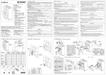
x 内容物一覧/必要となる工具 Packaged Items/Assembly Tools
c 操作と動作 Operating Instructions
●Never touch terminals. Otherwise, electric shock may result.
v 内部付属品の着脱 Fitting Internal Accessories
書
説明
取扱 ction
u
tr
s
In
取扱説明書
(本書)
Instruction Manual:1
(This document)
*
T2AL00L
or
Auxiliary Switch
④
*
T2AX00L
端子バリア(FCのみ)
Interpole Barrier
(Only FC)
スイッチディスコネクタ
Switch disconnector :1
④
③
Shunt Trip
TRIPPED
③
②
3P:2
4P:3
⑤
⑤
Alarm Switch
①
Undervoltage Trip
*
*
T2SH00L
T2UV00L
*付属品の図記号
*Symbols of Accessories
Ring Mark
ハンドル
Handle
取付ねじ
Mounting screw
表面形(FC)
Front
Connection
3P
2
4P
4
裏面形(RC)
Rear
Connection
3P
2
4P
4
差込形(PM)
Plug-in
Connection
3P
2
4P
4
埋込形(FP)
Flush Plate
Where Applicable
3P
2
4P
4
M4×55
M4×55
M4×65
M5×15
数
Qty
接続ねじ
Connecting screw
3P
6
4P
8
3P
6
4P
8
3P
6
4P
8
3P
6
4P
8
(ON)
Shunt Trip
power source
C1-C2
M8×18
(OFF)
組み合せ Combination
M8×25
M8
3 pole
数
Qty
M8×25
操作
Operation
8 17
5
6
○(OFF)⇒|(ON)
|(ON)⇒ ○(OFF)
TRIP⇒ ○(OFF)
ハンドル操作力
Operation effort
53N
57N
91N
取外し Removal
⑦
①①
①
①
①
②
⑥
⑥ 電線を成形
Form the cable
⑨
補助スイッチを1つ(または2つ)取付ける場合,
左側から順番に取付けて下さい。
In case of fiting one (or two) auxiliaryswitch,
fit in an order from a left side-slot.
Undervoltage Trip
power source
D1-D2
電線引き出し部の処理
Pull Out Leads on Load Side
⑧
RESET
10mm
*付属品の図記号
*Symbols of Accessories
4 pole
接続/極数
Connections/Poles
(TRIP)
トリップボタン
Trip Button
形式 Type
S250-SN
Auxiliary Switch
Alarm Switch
a
b
a
b
a contact
b contact a contact b contact
11/AXc-14/AXa 11/AXc-12/AXb
21/AXc-24/AXa 21/AXc-22/AXb 91 /ALc - 91 /ALc 31/AXc-34/AXa 31/AXc-32/AXb 94 /ALa 92 /ALb
41/AXc-44/AXa 41/AXc-42/AXb
AX
AL
SH
UV
・付属品取付け後,
必ず正常に動作することを確認してから,
ご使用下さい。
・After fitting, verify the function of the Accessory.
V
②
b 本体取付要領 表面形・裏面形
Breaker Mounting
Procedure for FC / RC
n 本体取付要領 埋込形 Breaker Mounting Procedure for F.P ( Where Applicable )
, 導体接続要領 裏面形・埋込形
Conductor Connection Procedure for RC / F.P ( Where Applicable )
L
④
②
B
8
①
M4×55 mm
1.3∼1.7N・m
③
②
フラッシュプレート
Flush Plate
②
B
φM
②
L
②
④
T2FP2501S*B
T2FP2502S*B
T2FP2510S*B
T2FP2511S*B
T2FP2512S*B
A
A
5
③
N
③
③
②
13
方向設定 Arrengment Set(0°
,45°
,90°
)
③
⁄0 本体取付要領 差込形
Breaker Mounting Procedure for PM
M5×15mm
3.6∼4.4N・m
裏面スタッド
Frat Bar Stud
①
T2RP25L*S
⑤
*:3 or 4(極数 Poles)
L
M
N
*:3 or 4(極数 Poles)
①
②
M6×18 mm
7.8∼11.8N・m
9mm
M8×25 mm
11.8∼18.6N・m
(OFF)
差込取付台
Plug-in Base
T2PM25LE*
T2PM25LC*
*:3 or 4(極数 Poles)
m 導体接続要領 表面形 Conductor Connection Procedure for FC
. ソルダレス端子導体接続要領 表面形
Solderless Terminals Mounting Procedure for FC
H
③
J
ソルダレス端子
Solderless Terminal
T2FW25LS*
φE
φI
F
C
D
E
F
G
H
I
C
≦22mm
≦11mm
8.4mm
≦25mm
≦11mm
≦7mm
9mm
⁄1 端子バリア取付要領
Interpole Barrier
Mounting Procedure
J
Q
*:3 or 4(極数 Poles)
J
K
M8×18
7.8∼12.7N・m
17 M10×25
22.5∼37.2N・m
O
P
Q
R
・電源側の裸導体間は,
ブレーカ端面まで全て絶縁して下さい。
・Insulate all bare conductors of the line side until the breaker end.
2G0954SAA(KRB-0613)
⁄2 端子カバー取付要領
Terminal Cover
Mounting Procedure
R2
(ON)
④
裏面キャップ
End cap
R
T2FW25LS*
≧23mm
≦120mm2
6 19N・m
M6×20mm
6.9∼9.3N・m
6
①
②
④
T2FB25L*S
T2FB25L*W
D
G
*:3 or 4(極数 Poles)
K
端子バー
Flat Bar
③
R2
※海外向け仕様品のみ
S
・取外しは取付けの逆手順で行います。
・When removing, remove the items in reverse order of mounting.
(OFF)時
Holding (OFF)
(ON)時
Holding (ON)
ハンドルホルダ
Handle Holder
T2HH25L
②
・取外しは取付けの逆手順で行います。
・When removing, remove the items in reverse order of mounting.
⁄4 ハンドルロック取付要領 Handle Lock Mounting Procedure
②
ハンドルロック
Handle Lock
T2HL25L
端子バリア
Interpole Barrier
接続
Connection
T2BA25L*SH
表面形
Front Connected
(FC)
*:3 or 4(極数 Poles)
裏面・差込形
Rear/Plug-in Connected
(RC / PM)
端子カバー
Terminal Cover
T2CF25L*SS
T2CF25L*SL
③
①
T2CF25L*SW
T2CR25L*
②
max ×3(φ5)
*:3 or 4(極数 Poles)
・取外しは取付けの逆手順で行います。
・When removing, remove the items in
reverse order of mounting.
・取外しは取付けの逆手順で行います。
・When removing, remove the items in
reverse order of mounting.
M4×65
1.3∼1.7N・m
P
10
T2CF20L
S
4極品の場合、取付ねじは4本となります。
For 4 pole, use the 4pcs mounting screw.
O
⁄3 ハンドルホルダ取付要領 Handle Holder Mounting Procedure
端子カバーロック
Terminal Cover Lock
③
・ハンドルロックは,
|(ON)
,
○(OFF)位置のいずれでも取付けできます。
・Handle lock can be fitted in any position of |(ON) and ○(OFF).
・取外しは取付けの逆手順で行います。
・When removing, remove the items in reverse order of mounting.
④