1
1 適用ブレーカ形式
□
2
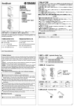
TemBreak
スライド式機械的
インターロック装置
取扱説明書
Slide Mechanical
Interlock Device
Instruction Manual
形式(Types):T2MS80
スライド式機械的インターロック
装置(以下インターロック装置と
呼称)は,隣接する2台の遮断器
のうちいずれか一方だけを投入で
きるようにする装置です。
ご使用に際しましては本書をよく
お読みのうえ正しくご使用下さい。
本書に述べていない取扱い,及び
誤った取扱いによって生じる損害に対して,弊社は一切責任を負いません。
工事が終わりましたら本書を需要家様にお届け下さい。
※内容をお断りなしに変更することがあります。ご了承下さい。
The slide mechanical interlock device allows only one breaker (TemBreak2) to be closed at
one time.
Please read these Instructions carefully to ensure correct use of the Device. The Manufacturer
assumes no responsibility for damages resulting from non-application or incorrect application
of the instructions provided herein.
This manual is to be delivered to the user after completion of the installation work.
*The contents of this manual may be subject to change without notice.
Applicable Breaker Type
インターロック
接続 *1 極数
形式
Connections Poles
Interlock type
適用ブレーカ形式
Applicable breaker type
S630-CF,S630-NF,S800-CF,S800-NF,
S630-CJ,S630-NJ,S800-CJ,S800-NJ,
S630-NE,S800-NE,S1000-CE
T2MS803SF FC, RC
3
ZS630-CF,ZS630-NF,ZS800-CF,ZS800-NF
ZAS630-CF,ZAS630-NF,
ZAS800-CF,ZAS800-NF
S630-CF,S630-NF,S800-CF,S800-NF,
T2MS804SF FC, RC
4 S630-NE,S800-NE,S1000-CE
S630-CJ,S630-NJ,S800-CJ,S800-NJ
*1:FC= 表面形 Front connected, RC= 裏面形 Rear connected
2 同梱品
□
Packaged Items
3P
4P
インターロック装置 Mechanical Interlock Device
なべねじ M6×14 2pcs.
Pan Head Screws
3 必要となる工具
□
Assembly Tools
4 安全上のご注意
□
4 Safety Notices
□
施工,使用,保守・点検の前に,必ずこの取扱説明書とその他の付属書類を
熟読し,正しくご使用下さい。機器の知識,安全の情報,そして注意事項の
全てについて習熟してからご使用下さい。本書では,安全注意事項のランク
を「危険」
,
「注意」として区分してあります。
Be sure to read these Instructions and other associated documents accompanying the product
thoroughly to be familiarize yourself with the product handling, safety information, and all other
precautions before mounting, using, servicing, or inspecting the product.
In these Instructions, safety notices are divided into "Warning" and "Caution" according to the
hazard level:
Warning : A warning notice with this symbol indicates that neglecting the suggested
procedure or practice could be fatal or result in serious personal injury.
Caution : A caution notice with this symbol indicates that neglecting the suggested
procedure or practice could result in moderate or slight personal injury and/or
property damage.
Note that failing to observe caution notices could result in serious injury/damage in some
situations. Because safety notices contain important information, be sure to read and observe
them.
危険:取扱いを誤った場合に,危険な状況が起こりえて,死亡叉は重傷を
受ける可能性が想定される場合。
注意:取扱いを誤った場合に,危険な状況が起こりえて,中程度の傷害や
軽傷を受ける可能性が想定される場合及び物的損害のみが想定され
る場合。
なお,「 注意」に記載した事項でも,状況によっては,重大な結果に結び
つく可能性があります。いずれも重要な内容を記載していますので,必ず守
って下さい。
危険
操作上のご注意
・充電端子部に触れないで下さい。感電の恐れがあります。
注意
施工上のご注意
・電気工事は,有資格者(電気工事士)が行って下さい。
・作業は,上位遮断器等を切(OFF)にし,主回路及び制御回路が充電
していないことを確認して行って下さい。感電の恐れがあります。
操作上のご注意
・自動的にブレーカがトリップ(遮断)した場合は,原因を取り除いてか
らON操作して下さい。火災の恐れがあります。
・インターロックレバーに過大な荷重を加えないで下さい。損傷の原因と
なります。
・オフロックされたブレーカをON操作しないで下さい。損傷の原因とな
ります。
Warning
Operation Precautions
・ Never touch live terminals. Doing so may result in electric shock.
Caution
Installation Precautions
・ Installation work must be performed by competent persons.
・ Prior to commencing any work on the product, open an upstream circuit breaker or the
like to isolate all sources of power/voltage. Doing so may result in electric shock.
Operation Precautions
・ When the breaker trips open automatically, remove the cause; then close the breaker.
Otherwise, a fire could result.
・ Do not apply excessive force to the interlock Lever. Otherwise, damage may occur.
・ Do not attempt to force an interlocked breaker into the closed position. Otherwise,
damage may occur.
5 取付け
□
Mounting
・施工に必要な各部の寸法は,カタログを確認して下さい。
・ For detailed mounting dimensions, refer to the catalouge.
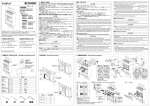
1 遮断器を○(OFF)にします。
◯
1 Turn off the breakers.
◯
2 遮断器を取付けます。
◯
2 Mounting the breakers.
◯
3 ねじ A を使用してインターロック装置を取付けます。
◯
3 Insert two screws “A” into the mounting holes of slide mechanical
◯
interlock device and then tighten them.
1
2
3
1
A
2
2
2
A
2
3
2
2
M6×16
A
4.6~6.0 N・m
2
5 ,□
6 の操作を行い正常に動作することを確認してから,ご使用下さい。
取付け後,必ず□
5 and □
6 .)
After mounting, verify the function of the Slide Mechanical Interlock Device. (Refer to □
※取外しは,上位遮断器等を切(OFF)にし,主回路及び制御回路が充電していないことを確認して行って下さい。感電の恐れがあります。
取外しは取付けの逆手順で行います。
* Prior to removing, open an upstream circuit breaker or the like to isolate all sources of power/voltage. Doing so may result in electric shock.
When removing, remove the items in reverse order of mounting.
7 右側ブレーカのオフロック操作
□
6 左側ブレーカのオフロック操作
□
Lock-in Off Operation of Right-side Breaker
Lock-in Off Operation of Left-side Breaker
1
2
2
インターロックレバー
Interlock Lever
1
インターロックレバー
Interlock Lever
3
補助ハンドル
Toggle extension
3
補助ハンドル
Toggle extension
1 左側の遮断器を○(OFF)にします。
◯
1 Turn off the left-side breaker.
◯
2 インターロックレバーを矢印の方向にスライドさせます。
◯
2 Slide the interlock lever of slide mechanical interlock device in the allow directions.
◯
3 左側の遮断器は○(OFF)状態にロックされ,右側の遮断器が┃(ON)可能とな
◯
ります。
3 The left-side breaker is locked in the ○(OFF) position and right-side breaker can be
◯
turned ON.
・補助ハンドルは外さないで下さい。インターロック装置が正常に操作でき
なくなります
・ Do not remove a Toggle extension. Lock-in Off operation is disabled.
1 右側の遮断器を○(OFF)にします。
◯
1 Turn off the right-side breaker.
◯
2 インターロックレバーを矢印の方向にスライドさせます。
◯
2 Slide the interlock lever of slide mechanical interlock device in the allow directions.
◯
3 右側の遮断器は○(OFF)状態にロックされ,左側の遮断器が┃(ON)可能とな
◯
ります。
3 The right-side breaker is locked in the ○(OFF) position and left-side breaker can be
◯
turned ON.
・補助ハンドルは外さないで下さい。インターロック装置が正常に操作でき
なくなります。
・ Do not remove a Toggle extension. Lock-in Off operation is disabled.
〒547-0002 大阪市平野区加美東 7-2-10
TEL:06(6791)9320/FAX:06(6791)9274/ホームページ: http://www.terasaki.co.jp
E メール: [email protected]
7-2-10 Kamihigashi, Hiranoku, Osaka 547-0002, Japan
Tel: 81-6-6791-9323 / Fax: 81-6-6791-9274 / Web Site: http://www.terasaki.co.jp
Email: [email protected]
2G0792SAA(KRB-0544)