Download YT-CAW503T Series
Transcript
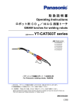
取 扱 説 明 書
Operating Instructions
ロボット用水冷式 CO2/MAG 溶接トーチ
Robotic Water-Cooled CO2/MAG Welding Torches
品番 /Model No.
YT-CAW503T Series
品番 / Model Number
YT-CAW503T0B
YT-CAW503T0C
YT-CAW503T0D
YT-CAW503T0E
YT-CAW503T0N
YT-CAW503T0M
パナソニック TAWERS 用クランプユニット付
With a Clamp Unit for Panasonic TAWERS
このたびは、パナソニック製品をお買い上げいただき、誠にありがとうございます。
• 取扱説明書をよくお読みのうえ、正しく安全にお使いください。
• ご使用前に「安全上のご注意」または「安全マニュアル」を必ずお読みください。
Before operating this product, please read the instructions carefully and save this manual for future use.
First of all, please read “Safety precautions” or “Safety manual”.
OM1105050JE03
1306
♦ もくじ
♦Table of Contents
はじめに ................................................. 3
Introduction ........................................... 9
1. 取付け .................................................. 4
1. Installation ........................................ 10
1.1 準備 ............................................................ 4
1.2 ロボット本体への取付 ............................... 4
1.3 パラメーターの設定................................... 4
1.1 Preparation..............................................10
1.2 Installing to Robot ..................................10
1.3 Setting Parameters .................................10
1.3.1 ツールオッフセットの設定 ........................ 4
1.3.2 負荷パラメーターの設定............................ 4
1.3.1 Tool Offset................................................ 10
1.3.2 Load Parameters...................................... 10
1.4 水ホースの接続 .......................................... 5
1.5 エアブロー用吸気口................................... 5
1.6 トーチケーブルの曲がり............................ 6
1.7 トーチボディーのコネクターへの取付け .. 6
1.4 Connecting Water Hoses .......................11
1.5 Inlet for Air Blow .....................................11
1.6 Curvature of Torch Cable.......................12
1.7 Installing Torch Body to Connector......12
2. 使用上の注意および保守点検 .............. 7
2. Caution for Use and Maintenace .... 13
2.1 使用上の注意.............................................. 7
2.2 保守点検..................................................... 7
2.1 Caution for Use .......................................13
2.2 Maintenance ............................................13
♦ 技術データ / Technical Data
3. 製品仕様/ Specifications................ 15
3.1 製品品番 / Model Numbers .....................15
3.2 共通定格仕様 / Common Specifications 15
3.3 付 属 品 / Accessories...........................15
3.4 外形図 / Dimensions................................15
4. 保守パーツ / Parts List...................... 16
4.1 トーチボディー部 /Torch Body Unit .......16
4.2 パワーケーブル部 /Power Cable Unit .....17
4.2.1 ワイヤクランプユニット / Wire Clamp Unit18
2
OM1105050JE03
♦ はじめに
本パナソニック溶接トーチ「YT-CAW503T シリーズ」
はメンテナンス性に優れ、トーチボディーの強度と
パワーケーブルの耐久性を向上させたパナソニック
溶接ロボット TAWERS シリーズ専用の水冷式 CO2/
MAG 溶接トーチです。据え付けおよび操作に先立
ち、溶接電源および溶接システムを構成する機器の
取扱説明書もご精読いただき、安全第一に作業をお
願いいたします。
製品品番
YT-CAW503T0B
YT-CAW503T0C
YT-CAW503T0D
YT-CAW503T0N
YT-CAW503T0E
適用ロボットタイプ
TA-1400WG(H) Ⅲ /WG(H)
TA-1600WG(H) Ⅲ /WG(H)
TA-1800WG(H) Ⅲ /WG(H)
TA-1900WG(H) Ⅲ /WG(H)
特殊仕様のため、適用ロ
ボットはありません。
YT-CAW503T0M
♦ 安全な使い方に関する警告表示
人への危害、財産の損害を防止するため、必ずお守りいただくことを説明しています。
危害や損害の程度を区分して、説明しています。
危険
警告
注意
お守りいただく内容を次の図記号で説明しています。
「死亡や重傷を負うおそれが大きい内
容」です。
してはいけない内容です。
「死亡や重傷を負うおそれがある内容」
です。
実行しなければならない内容です。
「軽傷を負うことや、財産の損害が発生
するおそれがある内容」です。
気をつけていただく内容です。
♦ 免責事項
下記のいずれかに該当する場合は、弊社ならびに本製品
の販売者は免責とさせて頂きます。
•正常な設置・保守・整備および定期点検が行われな
かった場合の不都合。
•天災地変、その他不可抗力による損害。
•弊社納入品以外の製品・部品不良、または不都合に伴
う本製品の問題、または本製品と弊社納入品以外の製
品、部品、回路、ソフトウェア等との組み合せに起因す
る問題。
•誤操作・異常運転、その他弊社の責任に起因せざる不
具合。
•本製品の使用(本製品の使用により製造された製品が
紛争の対象となる場合を含みます)に起因する、知的財
産権に関する問題。(プロセス特許に関する問題)
• 本製品が原因で生じる逸失利益・操業損失等の損害ま
たはその他の間接損害・派生損害・結果損害。
【本製品廃棄上のご注意】
本製品を廃棄される場合は、認可を受けた産業廃棄物処理業者と廃棄処理委託契約を締結し、廃棄処
理を委託してください。
• 本書の記載内容は、2013年 6月 現在のものです。
• 本書の記載内容は、改良のため予告なしに変更することがあります。
OM1105050JE03
3
取付け
1. 取付け
1.1 準備
ライナーが出ている時はパワーケーブルを回しな
がらライナー口金部の「O -リング」が完全に隠れ
るまで押し込んでください。
交換用 ラ イ ナーは長めに製作 さ れています。 交換
する時は、 突き出 し 長が L = 4 mm ~ 7 mm にな
る よ う に調整 し て く だ さ い。
回す
ライナー
パワーケーブル
押す
L
1.2 ロボット本体への取付
トーチボディー部分をセーフティホルダー YA-1AH011T11 に取付け、パワーケーブルのコネクター部分をワ
イヤフィーダーの CC 取付金具に接続します。トーチ取付け後は、セーフティホルダーの取扱説明書に従い、
ゲージを使用してトーチ先端の芯出しを行って下さい。
1.3 パラメーターの設定
パラメーターの設定方法の詳細は、ティーチペンダントの取扱説明書を参照してください。
1.3.1 ツールオッフセットの設定
取付けるロボットマニピュレータとセーフティホルダーの取扱説明書に従い、ツールオフセット値を設定し
ます。
1.3.2 負荷パラメーターの設定
• 負荷パラメーターを下表の通り設定します。
• FA 軸は、FA 軸に搭載した機器の負荷パラメーターを設定してください。
軸
TW
4
項目
X
Y
Z
質量(kg)
3.00
-
-
オフセット(mm)
117.8
0.3
117.9
イナーシャ(kg•m2)
0.00830
0.05548
0.04783
OM1105050JE03
取付け
1.4 水ホースの接続
トーチの水ホースは、付属の結束バンドで、トー
チケーブル、溶接パワーケーブルに沿わせて結束
し、冷却水装置の「行き水」および「戻り水」金具
に接続します。この時、水ホースは、UA アーム下
端まで溶接パワーケーブルに沿わせてください。
結束後、ロボットを動作させてトーチケーブル、
水ホースに余分な張力が掛かからないかチェック
し、状況に応じて結束位置、ホースの張り等を見直
してください。
結束
結束
注 記
• 水ホースを冷却水装置に接続する時、
「行き水」は
青色、
「戻り水」は赤色のホースを接続してくださ
い。逆に接続するとトーチ焼損の原因となります。
• 必要冷却水流量:1.2L/min、
推奨冷却水装置:パナ
ソニック YX-09KGC1
1.5 エアブロー用吸気口
本トーチのエアブローベース側面には、エアブ
ロー用の吸気口が用意されています。
エアブローベースカバーの下図の位置に φ10mm
の穴をあけて、エアブローベースに取付けられてい
る沈みプラグを取外してください。そして、付属の
[ エルボユニオン ] を取付けて使用してください。
14 mm
注 記
?
エアブロー用のスパッタチューブは、お客様手配
になっています。
沈みプラグ
φ 10 mm の穴を開ける
エアブローベースカバー
OM1105050JE03
エルボユニオン
5
取付け
1.6 トーチケーブルの曲がり
• ロボットのタイプにより適正なトーチケーブル長
が決められています。溶接トーチは正しい品番のも
のを使用してください。
• トーチケーブルに鋭角な曲がりがあると溶接ワイ
ヤの送給不良を起こすことがあります。トーチケー
ブルの曲がりに注意しながらティーチング作業を
行ってください。
1.7 トーチボディーのコネクターへの取付け
トーチボディーのコネクターへの挿入は、トーチ
ボディー部を持って作業してください。エアブロー
ベースカバーを持って作業すると、エアブローベー
スカバー破損の原因となります。
コネクター
エアブローベースカバー
トーチボディー
6
OM1105050JE03
使用上の注意および保守点検
2. 使用上の注意および保守点検
2.1 使用上の注意
• 溶接作業はアーク光や騒音が発生し、スパッタ、スラグ等が飛散します。溶接用保護面、耳栓、溶接用かわ製
保護手袋等の保護具を正しく使用してください。
• 溶接中、トーチ本体およびガスホース接続口は充電部になりますので触れないでください。
2.2 保守点検
注意
保守点検に先立ち配電箱および溶接電源、冷却水装置等の構成機器の電源
スイッチを切り、トーチが冷えてから行ってください。
安全および溶接品質確保のため Panasonic マーク入りの純正部品をお使いください。
♦ 日常点検
部品名
点検要領
チップ
作業を始める前に点検。穴が大きくなったものは交換
ノズル
作業を始める前に点検。ゆがんだものは交換
ライナー
毎週エアで洗浄。段落ちしたり、折れたものは交換
インナーチューブ
毎月シンナーで洗浄。入り口がだ円形に削れたものは交換
ワイヤ
クランプユニット
クランプユニットを取り外し、ワイヤガイドのワイヤ穴に高圧
エアを吹き付けて、ワイヤかすを除去する。取れない場合はシ
リンダーを取り外し、上部より清掃する。
♦ インナーチューブの交換方法
ナットカバーをずらしてコネクターをパワーケー
ブルから取り外した後、インナーチューブをトーチ
ボディーから引き抜いてください。
3
1
5
6
2
1
2
3
4
5
6
OM1105050JE03
4
トーチボディー
インナーチューブ
コネクター
ナットカバー
パワーケーブル
ワイヤクランプユニット
7
使用上の注意および保守点検
♦ ワイヤクランプユニットについて
(1)ワイヤクランプ内にワイヤかすがたまった場合
ワイヤクランプユニットを本トーチより取り外
し、ワイヤガイドのワイヤが通る穴に高圧エア
を吹き付けてください。
それでも解消しない場合は、シリンダーを取り
外してから上部より清掃してください。
(2)ワイヤガイドを交換する場合
(a)シリンダー (17) を取り外す。
(b)取り付け金具 (18) にある六角穴付き止めねじ
(21)、(22)、(23) を全て取り外す。
(c)ストッパー(19) を取り付け金具 (18) の上部側
から引き抜く。
(ストッパー (19) には1個所フ
ライス面がある。外す時にフライス面の方向
を確認する。)
(d)ワイヤガイド (20) をパワーケーブル側から引
き抜いて、新しいワイヤガイドと交換する。
(e)ストッパー(19) を取り付け金具 (18) の上部側
から挿入する。ストッパ (19) は溝部を上側に
し、フライス面と取り付け金具 (18) のストッ
パ固定ねじ部を一致させる。
(f)六角穴付き止めねじ(M 6)(21) を締込みス
トッパー (19) の高さを元あった時とおなじよ
うにする。
• 2 mm 径のゲージをワイヤ通路に挿入し、
ストッパ (19) とゲージが接触するように
六角穴付き止めねじ (21) を調整する。
• 六角穴付き止めねじ (21) には、取り外し
可能 なねじの緩み防止剤(スリーボンド
1401 B)を塗布する。
(g)ストッパー(19) を六角穴付き止めねじ(M 4)
(23) にて固定する。六角穴付き止めねじ (22)、
(23) には取り外し可能なねじの緩み防止剤
(ス
リーボンド1401 B)を塗布する。
No.
名 称
17
シリンダー
18
取り付け金具
18-1
ナットカバー
19
ストッパー
20
ワイヤガイド
21
六角穴付き止めねじ
22
六角穴付き止めねじ
23
六角穴付き止めねじ
24
エルボユニオン
25
スペーサー
26
O- リング
(h)シリンダー (17) を取り付ける。
8
OM1105050JE03
Introduction
♦Introduction
These water-cooled CO2/MAG welding torches are specially designed for Panasonic welding robots TAWERS
series. These torches feature easy maintenance and
improved torch body strength and power cable durability.
Please read “SAFETY MANUAL” and “Operating Instructions of the applied robot controller” prior to starting installation and operation of the robot.
Model Number
YT-CAW503T0B
YT-CAW503T0C
YT-CAW503T0D
YT-CAW503T0N
YT-CAW503T0E
YT-CAW503T0M
(Special Specifications)
Applicable Robot
TA-1400WG(H) Ⅲ /WG(H)
TA-1600WG(H) Ⅲ /WG(H)
TA-1800WG(H) Ⅲ /WG(H)
TA-1900WG(H) Ⅲ /WG(H)
N/A
♦Signal Words and Safety Symbols
Signal Words
DANGER
WARNING
CAUTION
Safety Symbols
Indicates an imminently hazardous
situation which, if not avoided, will
result in death or serious injury.
Indicates a prohibited
action.
Indicates a potentially hazardous
situation, which, if not avoided, could
result in death or serious injury.
Indicates a mandatory
action.
Indicates a potentially hazardous
situation, which, if not avoided, could
result in minor injury or property
damage.
Indicates a hazard alert.
♦Disclaimer
Panasonic Welding Systems Co., Ltd., (hereinafter called
“PWS”) and its affiliates (including any subcontractor, sales
company or agent) shall not assume or undertake any
responsibility or liability of the following:
• Any problem arising out of, or directly or indirectly attributable to,
the failure of user to carry out those normal installation, normal
maintenance, normal adjustment and periodical check of this
Product.
• Any problem arising out of any Force Majeure, including but not
limited to, act of God.
• Any malfunction or defect of this Product that is directly or indirectly the result of any malfunction or defect of one or more
related parts or products that are not supplied by PWS. Or any
problem arising out of, or directly or indirectly attributable to, the
combination of this Product with any other product, equipment,
devices or software that is not supplied by PWS.
• Any problem arising out of, or directly or indirectly attributable to,
user’s failure to strictly carry out or follow all of the conditions
and instructions contained in this instruction manual, or user’s
misusage, mishandle, operational miss or abnormal operation.
• Any problem arising out of this Product or the use of it, the
cause of which is other than the foregoing but is also not attributable to PWS.
• Any claim of a third party that this Product infringes the intellectual property rights of such third party that are directly or indirectly caused by User’s use of this Product and relate to the
method of production.
ANY LOST PROFITS OR SPECIAL, INDIRECT, INCIDENTAL OR CONSEQUENTIAL DAMAGES IN CONNECTION
WITH OR ARISING FROM ANY MALFUNCTION,
DEFECT OR OTHER PROBLEM OF THIS PRODUCT.
• This operating instructions manual is based on the information as of June, 2013.
• The information in this operating instructions manual is subject to change without notice.
• English version is the original.
OM1105050JE03
9
Installation
1.Installation
1.1 Preparation
When the liner cannot be put into the power cable, turn the
power cable clockwise and push the liner until the O-ring
disappears in the power cable.
Turn
Liner
Power cable
L
Push
1.2 Installing to Robot
The torch body portion is held with the safety holder, YA1AH011T11, and the connector of the power cable is connected to the wire feeder. After mounting the torch, adjust
the torch position. Refer to the operating instructions of
the safety holder.
1.3 Setting Parameters
Refer to the operating instructions of the robot teach pendant for detailed setting procedures.
1.3.1 Tool Offset
Set the tool offset data as shown in the operating instructions of the robot manipulator.
1.3.2 Load Parameters
• Set the load parameter shown below.
• The parameter for the FA axis is determined with the
load mounted on the FA axis.
Axis
TW
10
Items
X
Y
Z
Weight (kg)
3.00
-
-
Offset (mm)
117.8
0.3
117.9
Inertia (kg•m2)
0.00830
0.05548
0.04783
OM1105050JE03
Installation
1.4 Connecting Water Hoses
Set the water hoses along the torch cable and welding
cable, bind them together with plastic ties.
Keep binding up to end of the FA arm.
After fixing the water hose, connect them to a water cooling
unit and check that the hoses and cables have no extra
tension with the robot motion.
Note
• Connect the blue hose to supply water and the red hose
to drain water. Connecting the wrong hose could
cause torch burnout.
Bind
Bind
• Required cooling water flow rate:1.2L/min.
Recommended water cooling unit: Panasonic YX09KGC1
1.5 Inlet for Air Blow
This torch is provided with a hole for the air blow inlet at the
side of the air blow base. Refer to the following figure and
make a hole of 10 mm diameter in the air blow base cover,
and remove the sunk plug from the air blow base. Then
attach the attached elbow union instead.
14 mm
Note
Spatter tube for air blow unit is customer supplied.
Sunk plug
Make a hole of φ 10 mm.
Air blow base cover
OM1105050JE03
Elbow union
11
Installation
1.6 Curvature of Torch Cable
• Appropriate torch cable length is designed for each
robot type. Use a right welding torch.
• Sharply bent torch cable makes wire feeding troubles.
Watch curvature of the torch cable at robot teaching
operation.
R300 or more
1.7 Installing Torch Body to Connector
Make sure to hold the torch body to insert it into the connector. Holding the air blow base cover to insert the torch
body into the connector can damage the air blow base
cover.
Connector
Air blow base cover
Torch body
12
OM1105050JE03
Caution for Use and Maintenace
2.Caution for Use and Maintenace
2.1 Caution for Use
• Welding work generates arc ray, noise, spatters and
slag. Protect yourself and others.
• Do not touch torch body and gas hose connecting metals
during welding. They are electrically charged.
Nozzle of water-cooled welding torch is also electrically
charged.
2.2 Maintenance
CAUTION
Before operation, turn off all input power for welding power source, robot controller and all equipment connected.
Use genuine Panasonic replacement parts to keep safe
and long durable operation.
♦Daily Maintenance
Parts
Maintenance
Contact tip
Check it before daily operation. Replace a large hole tip.
Nozzle
Check it before daily operation. Replace a deformed nozzle.
Liner
Clean it every week. Replace a bent or deformed liner.
Inner tube
Clean it with solvent. Replace a tube with deformed entrance.
Wire clamp unit
Detach the wire cramp unit from the torch, and blow high-pressure
air to the hole of the wire guide. If the refuse still remains, detach the
cylinder and clean it from the top side.
♦Replacement of Inner Tube
Turn nut cover and remove connector from power cable.
Pull Inner tube out of torch body.
4
3
1
6
2
1
2
3
4
5
OM1105050JE03
5
Torch body
Inner tube
Connector
Nut cover
Power cable
13
Caution for Use and Maintenace
♦Wire Clamp Unit
(1) When the wire residue builds up in the wire clamp:
Remove the wire clamp unit from the torch body, and
then use the high pressure air to blow the wire residue
off from the hole of the wire guide. If the wire reside
still remains, remove the cylinder to clean the hole
from the top side.
(2) How to replace the wire guide
(a) Remove the cylinder (17).
(b) Remove hexagon socket setscrews (21), (22) and
(23) at the fixture (18).
(c) Pull out the stopper (19) from the top side of the
fixture (18). (The stopper (19) has a machined flat
surface. Check the orientation of the surface.)
(d) Pull out the wire guide (20) from the power cable
side, and replace it with a new one
(e) Insert the stopper (19) from the top side of the fixture (18). Make sure to place the groove of the
stopper upward so as to match the machine flat
surface of the stopper (19) and the stopper fastening screw of the fixture (18).
(f) Fasten the hexagon socket setscrew (M6) (21) so
that the height of the stopper (19) becomes the
same as before it was removed.
• Insert the 2 mm diameter gauge into the wire
path.
Adjust the hexagon socket setscrew (21) so
that the gauge and the stopper (19) touch.
• Apply the removable anti-loosening agent;
THREE BOND 1401B, to the hexagon socket
setscrew (21).
(g) Fix the stopper (19) with the hexagon socket setscrew (M4) (23). Apply the removable anti-loosening agent; THREE BOND 1401B, to the hexagon
socket setscrews (22) and (23).
(h) Reinstall the cylinder (17).
14
No.
Part name
17
Cylinder
18
Fixture
18-1
Nut cover
19
Stopper
20
Wire guide
21
Hexagon socket setscrew
22
Hexagon socket setscrew
23
Hexagon socket setscrew
24
Elbow union
25
Spacer
26
O-ring
OM1105050JE03
製品仕様/ Specifications
♦ 技術データ / Technical Data
3. 製品仕様/ Specifications
3.1 製品品番 / Model Numbers
製品品番 /Model #
トーチケーブル長 /Torch cable length
質 量 /Weight
YT-CAW503T0B
YT-CAW503T0C
YT-CAW503T0D
YT-CAW503T0N
YT-CAW503T0E
YT-CAW503T0M
1.2 m
1.4 m
3.0 kg
3.0 kg
1.6 m
3.2 kg
1.7 m
3.5 m
3.2 kg
5.1 kg
• トーチボディはキー無し。
• The torch body does not have a key.
3.2 共通定格仕様 / Common Specifications
CO2
CO2(20%)+Ar(80%)
CO2(20%)+Ar(80%)
使用率
( 溶接電流-使用率 )
パルス溶接時の使用率
適用ワイヤ材質
適用ワイヤ径
Duty cycle
(Amp-duty cycle)
トーチ形状
Torch shape
冷却方式
Cooling system
必要冷却水量
Required water flow rate
ワイヤ送給装置との接続
Connection with a wire feeder
For pulsed welding
Applicable wire
Applicable wire dia.
500A-100%
500A-100%
500A-80% (450A-100%)
軟鋼ソリッド , FCW / Mild steel solid, FCW
1.2 (*) [mm]
R=64 mm,
θ=31°,
L=127.5 mm
水冷 / Water cooled
注 記
1.2 L/min
CC 取り付け金具接続 / CC metal fitting
Note
(*):記載値以外のワ イ ヤ径の対応は別途部品購入が必要で
す。 後述の 「保守パーツ」 を参照 く だ さ い。
(*): Welding for the wire sizes other than the above listed
requires optional parts. See “Parts list” section.
3.3 付 属 品 / Accessories
品名
6角レンチ
キャップ
-
Description
Hex. wrench
Cap
-
品番 /Par #
数量 / Q’ty
HWK5
TFK00010
-
1
1
-
Description
品名
Elbow
union
エルボユニオン
Plastic tie
結束バンド
Plastic tie
結束バンド
品番 /Part #
KQ2L06-01S
PTL21M0
PLT3S0
数量 / Q’ty
1
10
2
3.4 外形図 / Dimensions
※
※T0N 以外 / Other than T0N:70.5
T0N:120.5
OM1105050JE03
15
保守パーツ / Parts List
4. 保守パーツ / Parts List
4.1 トーチボディー部 /Torch Body Unit
No
1
1-1
2
3
4
Description
トーチボディー
Torch body
0- リング
O-ring
ワンタッチ継手
One-touch joint
インナーチューブ
品 番
数量
Part No.
Q'ty
TCX00894
1
備考
Note
T0N 用
For T0N
TCX00892
1
P8V
(1)
KQ2H06-08
2
TGT00708
1
T0N 用
1.2 mm -1.6 mm 用
For T0N
For 1.2 mm-1.6 mm
TGT00709
1
T0N 以外用
1.2 mm -1.6 mm 用
For other thanT0N
For 1.2 mm-1.6 mm
TGT00181
-
T0N 用別売品
0.9 mm -1.2 mm 用
Option for T0N
For 0.9 mm -1.2 mm
TGT00182
-
T0N 以外用別売品
0.9 mm -1.2 mm 用
Option for other than T0N
0.9 mm-1.2 mm
1
1.2mm ワイヤ用
For 1.2 mm wire
Inner tube
R チップ 1.2
Contact tip (R-1.2)
TET01297
R チップ 0.9
Contact tip (R-0.9)
TET00959
-
別売品 0.9 mm 用
0.9 mm, optional
R チップ 1.0
Contact tip (R-1.0)
TET01068
-
別売品 1.0 mm 用
1.0 mm, optional
R チップ 1.4
Contact tip (R-1.4)
TET01448
-
別売品 1.4 mm 用
1.4 mm, optional
別売品 1.6 mm 用
1.6 mm, optional
R チップ 1.6
Contact tip (R-1.6)
TET01692
-
TGR00015
1
Insulator
TFZ00034
1
6-1
オリフィス
インシュレーター
0- リング
Orifice
O-ring
P21V
(1)
6-2
0- リング
O-ring
S14V
(2)
6-3
0- リング
O-ring
S18V
(1)
TGN00140
1
Air blow assembly
AFM41756
1
Air blow base
AJM41121
(1)
No.8 に含む
Included in No.8.
8-2
ノズル
エアブロー組立品
エアブローベース
0- リング
Nozzle
P20V
(5)
No.8 に含む
Included in No.8
8-3
ハーフユニオン
Half union
KQ2H06M5
(2)
No.8 に含む
Included in No.8
沈みプラグ
止め輪
Blind plug
SP1/8B
(1)
No.8 に含む
Included in No.8.
Snap ring
STW19
1
TRB0604R
1
Power cable length +
0.6 m (Red)
TRB0604BU
1
パワーケーブル長
+0.6 m(赤)
パワーケーブル長
+0.6 m(青)
5
6
7
8
8-1
8-4
9
10
16
名 称
O-ring
スパッタチューブ(*1) Spatter tube(*1)
Power cable length +
0.6 m (Blue)
OM1105050JE03
保守パーツ / Parts List
No
11
12
13
14
15
15-1
16
17
18
品 番
数量
Part No.
Q'ty
Hose adapter
AWB41006
2
Ring
TGM00007
1
Water tube
TCW00004
1
Setscrew
TGM00006
1
Connector
AJU41005
1
Clamping bolt
XVE6C15
(1)
Rubber cover
TZK00007
1
Air blow base cover
AZK31002
1
Description
名 称
ホースアダプター
リング
水筒
止めねじ
コネクター
締め付けボルト
ゴムカバー
エアブローベースカ
バー
スパッタチューブ(*1) Spatter tube(*1)
備考
Note
TRB0806R
1
9 m (赤)
9 m (Red)
TRB0806BU
1
9 m (青)
9 m (Blue)
*1:スパッタチューブを注文するときは、品番、数量と共に長さも指定してください。
*1:Along with part number and quantity, length required when ordering spatter tube.
4.2 パワーケーブル部 /Power Cable Unit
品番
Model number
YT-CAW503T0B
YT-CAW503T0C
YT-CAW503T0D
YT-CAW503T0N
YT-CAW503T0E
YT-CAW503T0M
No
1-1
1-2
1-3
1-4
1-5
1-6
1-7
1-8
2-1
名 称
ナットカバー
保護筒
保護筒
信号ケーブル1
信号ケーブル2
信号ケーブル組立品
ガスホース
エルボユニオン
O リング
OM1105050JE03
1
2
(2)
パワーケーブル組立品
ライナ- (S121)
ライナ- (S091)
Power cable assembly
Liner (S091)
TDT00137
TDT00204
TDX00179
TDX00183
(1.2 m)
(1.4 m)
Liner (S121)
TDT00136
TDT00203
TDX00185
(1.6 m)
TDT00140
TDT00141
TDX00187
TDX00297
(1.7 m)
(3.5 m)
TDT00140
TDT00058
TDT00141
TDT00061
Description
品番
数量
Part No.
Q’ty
1
1
1
1
1
1
1
1
1
Nut cover
TZK00008
Protection tube
TFP00026
Protection tube
TFP00027
Signal cable 1
TWX00031
Signal cable 2
TWX00033
Signal cable ass’y
AWC42306
Gas hose
AWG41018
Elbow union
KQ2LF0601
O-ring
P7
備考
Note
17
保守パーツ / Parts List
4.2.1 ワイヤクランプユニット / Wire Clamp Unit
ADU01568
27
No
17
18
18-1
19
20
21
22
23
24
25
26
27
Description
名 称
品番
数量
備考
Q’ty
1
Note
シリンダー
取り付け金具
ナットカバー
ストッパー
ワイヤガイド
六角穴付き止めねじ
六角穴付き止めねじ
六角穴付き止めねじ
エルボユニオン
スペーサー
O- リング
Cylinder
Part No.
TMC00001
Fixture
AFM41724
1
Nut cover
TZK00008
(1)
Stopper
TFM00087
1
Wire guide
AGT41135
1
Hexagon socket setscrew
XXE6D6FP
1
M6x6
Hexagon socket setscrew
XXE4D8FP
1
M4x8
Hexagon socket setscrew
XXE4D8FP
1
M4x8
Elbow union
KQL06M5
1
Spacer
TFS00004
1
O-ring
P16
1
スパッタチューブ
Spatter tube(*1)
TRB0604B
1
(*1)
パワーケーブル長 +0.55 m
Power cable lengh + 0.55 m
*1:スパッタチューブを注文するときは、品番、数量と共に長さも指定してください。
*1:Along with part number and quantity, length required when ordering spatter tube.
18
OM1105050JE03
OM1105050JE03
19
パナソニック溶接システム株式会社
〒 561-0854 大阪府豊中市稲津町 3 丁目 1 番 1 号
TEL: (06)-6866-8556(代表)
FAX: (06)-6862-1441
ホームページ : http://panasonic.co.jp/pws/
© Panasonic Welding Systems Co., Ltd. 2011
Panasonic Welding Systems Co., Ltd.
1-1, 3-chome, Inazu-cho, Toyonaka, Osaka 561-0854, Japan
TEL: 81-6-6866-8505
FAX: 81-6-6866-0709
URL:http://panasonic.net/pws/
Printed in Japan.
OM1105050JE03


