1
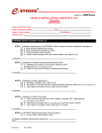
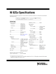
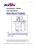
I-HTE-600
ORIGINAL INSTRUCTIONS
Installation, Setup
and Operation
INSTRUCTIONS
for
SUNNEN® HTE-SERIES TUBE HONE
Model: HTE-1600WE/WCE & HTE-1600WG/WCG
READ THE FOLLOWING INSTRUCTIONS THOROUGHLY AND CAREFULLY BEFORE UNPACKING,
INSPECTING, OR INSTALLING THE SUNNEN® TUBE HONE.
“SUNNEN® AND THE SUNNEN LOGO ARE REGISTERED TRADEMARKS OF SUNNEN PRODUCTS COMPANY.”
SUNNEN ® PRODUCTS COMPANY • 7910 MANCHESTER ROAD • ST. LOUIS, MO 63143, U.S.A. • PHONE: 314-781-2100
GENERAL INFORMATION
The Sunnen® equipment has been designed and engineered for a wide variety of parts within the capacity and limitation of the equipment. With proper care
and maintenance this equipment will give years of service.
READ THE FOLLOWING INSTRUCTIONS CAREFULLY AND THOROUGHLY BEFORE UNPACKING, INSPECTING, OR INSTALLING THIS EQUIPMENT.
IMPORTANT: Read any supplemental instructions BEFORE installing this equipment. These supplemental instructions give you important information to
assist you with the planning and installation of your Sunnen equipment.
Sunnen Technical Service Department is available to provide telephone assistance for installation, programming, & troubleshooting of your Sunnen
equipment. All support is available during normal business hours, 8:00 AM to 4:30 PM Central Time.
Review all literature provided with your Sunnen equipment. This literature provides valuable information for proper installation, operation, and maintenance
of your equipment. Troubleshooting information can also be found within the Instructions. If you cannot find what you need, call for technical support.
Where applicable, programming information for your Sunnen equipment is also included. Most answers can be found in the literature packaged with your
equipment.
Help us help you. When ordering parts, requesting information, or technical assistance about your equipment, please have the following
information available:
• Have ALL MANUALS on hand. The Customer Services Representative or Technician will refer to it.
• Have Model Number and Serial Number printed on your equipment Specification Nameplate.
• Where Applicable: Have Drive model and all nameplate data. Motor type, brand, and all nameplate data.
For Troubleshooting, additional information may be required:
• Power distribution information (type - delta, wye, power factor correction; other major switching devices used, voltage fluctuations)
• Installation Wiring (separation of power & control wire; wire type/class used, distance between drive and motor, grounding).
• Use of any optional devices/equipment between the Drive & motor (output chokes, etc.).
For fast service on your orders call:
Sunnen Automotive Customer Service toll free at: 1-800-772-2878
Sunnen Industrial Customer Service toll free at: 1-800-325-3670
Customers outside the USA, contact your local authorized Sunnen Distributor.
Additional information available at: http://www.sunnen.com or e-mail: [email protected]
NOTE: Sunnen reserves the right to change or revise specifications and product design in connection with any feature of our products contained herein.
Such changes do not entitle the buyer to corresponding changes, improvements, additions, or replacements for equipment, supplies or accessories
previously sold. Information contained herein is considered to be accurate based on available information at the time of printing. Should any discrepancy of
information arise, Sunnen recommends that user verify the discrepancy with Sunnen before proceeding.
ESD PREVENTION REVIEW
Let's review the basics of a sound static control system and its effective implementation. First, in the three step plan:
1.
Always ground yourself when handling sensitive components or assemblies.
2.
Always use a conductive or shielded container during storage or transportation. These materials create a Faraday
cage which will isolate the contents from static charges.
3.
Open ESD safe containers only at a static safe work station.
At the static safe work station, follow these procedures before beginning any work:
A.
Put on your wrist strap or foot grounding devices.
B.
Check all grounding cords to make sure they are properly connected to ground, ensuring the effective dissipation of static charges.
C.
Make sure that your work surface is clean and clear of unnecessary materials, particularly common plastics.
D.
Anti-static bubble wrap has been included for use at the machine when an ESD safe workstation is not available.
You are now properly grounded and ready to begin work. Following these few simple rules and using a little common sense will go a long
way toward helping you and your company in the battle against the hazards of static electricity. When you are working with ESD sensitive devices, make sure you:
GROUND
ISOLATE
NEUTRALIZE
ii
SUNNEN® LIMITED PRODUCT WARRANTY
Sunnen® Products Company and its subsidiaries (SPC) warrant that all new SPC honing machines, gaging equipment, tooling, and related equipment will
be free of defects in material and/or workmanship for a period of one year from the date of original shipment from SPC.
Upon prompt notification of a defect during the one-year period, SPC will repair, replace, or refund the purchase price, with respect to parts that prove to be
defective (as defined above). Any equipment or tooling which is found to be defective from improper use will be returned at the customer's cost or repaired
(if possible) at customer's request. Customer shall be charged current rates for all such repair.
Prior to returning any SPC product, an authorization (RMA) and shipping instructions must be obtained from the Customer Service Department or items sent
to SPC will be returned to the customer.
Warranty Limitations and Exclusions This Warranty does not apply to the following:
• Normal maintenance items subject to wear and tear: (belts, fuses, filters, etc).
• Damages resulting from but not limited to:
› Shipment to the customer (for items delivered to customer or customer's agent F.O.B., Shipping Point)
› Incorrect installation including improper lifting, dropping and/or placement
› Incorrect electric power (beyond +/- 10% of rated voltage) including intermittent or random voltage spikes or drops
› Incorrect air supply volume and/or pressure and/or contaminated air supply
› Electromagnetic or radio frequency interference from surrounding equipment (EMI, RFI)
› Storm, lightning, flood or fire damage
› Failure to perform regular maintenance as outlined in SPC manuals
› Improper machine setup or operation causing a crash to occur
› Misapplication of the equipment
› Use of non-SPC machines, tooling, abrasive, fixturing, coolant, repair parts, or filtration
› Incorrect software installation and/or misuse
› Non-authorized customer installed electronics and/or software
› Customer modifications to SPC software
THE LIMITED WARRANTY DESCRIBED HEREIN IS EXPRESSLY IN LIEU OF ALL ANY OTHER WARRANTIES. SPC MAKES NO REPRESENTATION OR WARRANTY OF ANY
OTHER KIND, EXPRESS OR IMPLIED, WHETHER AS TO MERCHANTABILITY, FITNESS FOR A PARTICULAR PURPOSE OR ANY OTHER MATTER. SPC IS NOT
RESPONSIBLE FOR THE IMPROPER USE OF ANY OF ITS PRODUCTS. SPC SHALL NOT BE LIABLE FOR DIRECT, INDIRECT, INCIDENTAL, OR CONSEQUENTIAL
DAMAGES INCLUDING BUT NOT LIMITED TO: LOSS OF USE, REVENUE, OR PROFIT. SPC ASSUMES NO LIABILITY FOR PURCHASED ITEMS PRODUCED BY OTHER
MANUFACTURERS WHO EXTEND SEPARATE WARRANTIES. REGARDLESS OF ANY RIGHTS AFFORDED BY LAW TO BUYER, SPC's LIABILITY, IF ANY, FOR ANY AND
ALL CLAIMS FOR LOSS OR DAMAGES WITH RESPECT TO THE PRODUCTS, AND BUYER'S SOLE AND EXCLUSIVE REMEDY THEREFORE, SHALL IN ALL EVENTS BE
LIMITED IN AMOUNT TO THE PURCHASE PRICE OF THAT PORTION OF THE PRODUCTS WITH RESPECT TO WHICH A VALID CLAIM IS MADE.
Shipping Damages
Except in the case of F.O.B., Buyer's destination shipments, SPC will not be liable for any settlement claims for obvious and/or concealed shipping damages.
The customer bears the responsibility to unpack all shipments immediately and inspect for damage. When obvious and/or concealed damage is found, the
customer must immediately notify the carrier's agent to make an inspection and file a claim. The customer should retain the shipping container and packing
material.
SUNNEN® SOFTWARE LICENSE AGREEMENT
This document is a Legal Agreement between you, as user and licensee (Licensee), and Sunnen® Products Company (SPC) with respect to preprogrammed
software (Software) provided by SPC for use on SPC Equipment. By using the Software, you, as Licensee, agree to become bound by the terms of this
Agreement.
In consideration of payment of the license fee (License Fee) which is part of the price evidenced by your receipt (Receipt), SPC grants to you as Licensee
a non-exclusive right, without right to sub-license, to use the particular copy of the SPC Software licensed hereunder only on the particular equipment sold with
the Software. SPC reserves all rights including rights not otherwise expressly granted, and retain title and ownership to the Software including all subsequent
copies or updates in any media. The Software and all accompanying written materials are covered by copyrights owned by SPC. If supplied on removable
media (floppy disk), you, as Licensee, may copy the Software only for back up purposes; or you may request that SPC copy the Software for you for the
same purposes. All other copying of the Software or of the accompanying written materials is expressly forbidden and is in violation of the Agreement.
The Software and accompanying written materials (including the user's manual, if any) are provided in an "as is" condition without warranty of any kind
including the implied warranties of merchantability and fitness for a particular purpose, even if SPC has been advised of this purpose. SPC specifically does
not warrant that it will be liable as a result of the operation of the Software for any direct, indirect, consequential or accidental damages arising out of the
use of or inability to use such product even if SPC has been advised of the possibility of such use. It is recognized that some states do not allow the exclusion or limitation of liability for consequential or accidental damages and to the extent this is true, the above limitations may not apply.
Any alteration or reverse engineering of the software is expressly forbidden and is in violation of this agreement.
SPC reserves the right to update the software covered by this agreement at any time without prior notice and any such updates are covered by this
agreement.
iii
SAFETY INSTRUCTIONS
READ FIRST
This machine, like any equipment, may be dangerous if used improperly. Please
read all warnings and instructions before attempting to use this machine.
Always disconnect power at main enclosure before servicing machine.1
Always wear eye protection when operating this machine.
NEVER open or remove any machine cover or protective guard with power "ON."
Always disconnect power at main enclosure before servicing this equipment.1
DO NOT attempt any repair or maintenance procedure beyond those described in
this book. Contact your Sunnen® Field Service Engineer or Technical Services
Representative for repairs not covered in these instructions.
Due to the wide variety of machine configurations, all possibilities cannot be
described in these instructions. Instructions for safe use and maintenance of
optional equipment ordered through Sunnen, will be provided through separate
documentation and/or training provided by your Sunnen Field Service Engineer or
Technical Services Representative.
DO NOT attempt to defeat any safety device on this machine or on any of the
optional equipment.
If specially built automation components are added to this system, be sure that
safety is not compromised. If necessary, obtain special enlarged work area safety
system from Sunnen Products Co.
1
DO NOT touch electrical components until main input power has been turned off and CHARGE
lamps are extinguished. WARNING: The capacitors are still charged and can be quite dangerous.
iv
TABLE OF CONTENTS
Page
TABLE OF CONTENTS . . . . . . . . . . . . . . . . . . . . . . . . . . . . . . . . . . . . . . . . . . . . . . . . . . . . . . . . . . . . . . . . v
LIST OF APPENDIXES . . . . . . . . . . . . . . . . . . . . . . . . . . . . . . . . . . . . . . . . . . . . . . . . . . . . . . . . . . . . . . . . v
INTRODUCTION . . . . . . . . . . . . . . . . . . . . . . . . . . . . . . . . . . . . . . . . . . . . . . . . . . . . . . . . . . . . . . . . . . . . . vi
GENERAL INFORMATION & SPECIFICATIONS . . . . . . . . . . . . . . . . . . . . . . . . . . . . . . . . . . . . . . . . vii
FLOOR LAYOUT (Configuration) . . . . . . . . . . . . . . . . . . . . . . . . . . . . . . . . . . . . . . . . . . . . . . . . . . . . . . viii
INSTALLATION . . . . . . . . . . . . . . . . . . . . . . . . . . . . . . . . . . . . . . . . . . . . . . . . . . . . . . . . . . . . . . . . . . . . . . . 1
Purpose . . . . . . . . . . . . . . . . . . . . . . . . . . . . . . . . . . . . . . . . . . . . . . . . . . . . . . . . . . . . . . . . . . . . . . . . . . . . . . 1
Tooling & Materials . . . . . . . . . . . . . . . . . . . . . . . . . . . . . . . . . . . . . . . . . . . . . . . . . . . . . . . . . . . . . . . . . . . . 1
Installation . . . . . . . . . . . . . . . . . . . . . . . . . . . . . . . . . . . . . . . . . . . . . . . . . . . . . . . . . . . . . . . . . . . . . . . . . . . . 1
Electrical Requirements . . . . . . . . . . . . . . . . . . . . . . . . . . . . . . . . . . . . . . . . . . . . . . . . . . . . . . . . . . . . . . . . . . 2
Optional Accessories . . . . . . . . . . . . . . . . . . . . . . . . . . . . . . . . . . . . . . . . . . . . . . . . . . . . . . . . . . . . . . . . . . . . 3
Optional Light Curtain . . . . . . . . . . . . . . . . . . . . . . . . . . . . . . . . . . . . . . . . . . . . . . . . . . . . . . . . . . . . . . . . . . 4
Light Curtain Function Check . . . . . . . . . . . . . . . . . . . . . . . . . . . . . . . . . . . . . . . . . . . . . . . . . . . . . . . . . . . . .4
Operational Check . . . . . . . . . . . . . . . . . . . . . . . . . . . . . . . . . . . . . . . . . . . . . . . . . . . . . . . . . . . . . . . . . . . . . 5
PREPARING FOR OPERATION . . . . . . . . . . . . . . . . . . . . . . . . . . . . . . . . . . . . . . . . . . . . . . . . . . . . . . . . . . 7
General . . . . . . . . . . . . . . . . . . . . . . . . . . . . . . . . . . . . . . . . . . . . . . . . . . . . . . . . . . . . . . . . . . . . . . . . . . . . . . 7
Major Components . . . . . . . . . . . . . . . . . . . . . . . . . . . . . . . . . . . . . . . . . . . . . . . . . . . . . . . . . . . . . . . . . . . . . 7
Safety Symbols . . . . . . . . . . . . . . . . . . . . . . . . . . . . . . . . . . . . . . . . . . . . . . . . . . . . . . . . . . . . . . . . . . . . . . . . 7
Operator Controls . . . . . . . . . . . . . . . . . . . . . . . . . . . . . . . . . . . . . . . . . . . . . . . . . . . . . . . . . . . . . . . . . . . . . . 7
Honing Tool . . . . . . . . . . . . . . . . . . . . . . . . . . . . . . . . . . . . . . . . . . . . . . . . . . . . . . . . . . . . . . . . . . . . . . . . . . . 7
SETUP AND OPERATION . . . . . . . . . . . . . . . . . . . . . . . . . . . . . . . . . . . . . . . . . . . . . . . . . . . . . . . . . . . . . . . 9
General . . . . . . . . . . . . . . . . . . . . . . . . . . . . . . . . . . . . . . . . . . . . . . . . . . . . . . . . . . . . . . . . . . . . . . . . . . . . . . 9
Safety Precautions . . . . . . . . . . . . . . . . . . . . . . . . . . . . . . . . . . . . . . . . . . . . . . . . . . . . . . . . . . . . . . . . . . . . . . 9
Setup & Operation . . . . . . . . . . . . . . . . . . . . . . . . . . . . . . . . . . . . . . . . . . . . . . . . . . . . . . . . . . . . . . . . . . . . . . 9
ROUTINE MAINTENANCE . . . . . . . . . . . . . . . . . . . . . . . . . . . . . . . . . . . . . . . . . . . . . . . . . . . . . . . . . . . . 13
General . . . . . . . . . . . . . . . . . . . . . . . . . . . . . . . . . . . . . . . . . . . . . . . . . . . . . . . . . . . . . . . . . . . . . . . . . . . . . 13
Cleaning . . . . . . . . . . . . . . . . . . . . . . . . . . . . . . . . . . . . . . . . . . . . . . . . . . . . . . . . . . . . . . . . . . . . . . . . . . . . 13
Lubrication . . . . . . . . . . . . . . . . . . . . . . . . . . . . . . . . . . . . . . . . . . . . . . . . . . . . . . . . . . . . . . . . . . . . . . . . . . 13
Pneumatic Line Check . . . . . . . . . . . . . . . . . . . . . . . . . . . . . . . . . . . . . . . . . . . . . . . . . . . . . . . . . . . . . . . . . . 14
Coolant Line Check . . . . . . . . . . . . . . . . . . . . . . . . . . . . . . . . . . . . . . . . . . . . . . . . . . . . . . . . . . . . . . . . . . . . 14
Coolant Reservoir . . . . . . . . . . . . . . . . . . . . . . . . . . . . . . . . . . . . . . . . . . . . . . . . . . . . . . . . . . . . . . . . . . . . . 14
Light Curtain Cleaning . . . . . . . . . . . . . . . . . . . . . . . . . . . . . . . . . . . . . . . . . . . . . . . . . . . . . . . . . . . . . . . . . 14
Coolant Filter Unit . . . . . . . . . . . . . . . . . . . . . . . . . . . . . . . . . . . . . . . . . . . . . . . . . . . . . . . . . . . . . . . . . . . . 15
TROUBLESHOOTING . . . . . . . . . . . . . . . . . . . . . . . . . . . . . . . . . . . . . . . . . . . . . . . . . . . . . . . . . . . . . . . . . 17
General . . . . . . . . . . . . . . . . . . . . . . . . . . . . . . . . . . . . . . . . . . . . . . . . . . . . . . . . . . . . . . . . . . . . . . . . . . . . . 17
Operational Troubleshooting . . . . . . . . . . . . . . . . . . . . . . . . . . . . . . . . . . . . . . . . . . . . . . . . . . . . . . . . . . . . . 17
APPENDIXES
A Coolant Flow Diagram . . . . . . . . . . . . . . . . . . . . . . . . . . . . . . . . . . . . . . . . . . . . . . . . . . . . . . . . . . . . . . . . 19
B Declaration of Conformity . . . . . . . . . . . . . . . . . . . . . . . . . . . . . . . . . . . . . . . . . . . . . . . . . . . . . . . . . . . . . 21
v
INTRODUCTION
This Instruction Manual is provided to give the information required to install, operate, and maintain the
Sunnen® HTE-Series Tube Hones, models HTE-1600.
As there are numerous Workpieces that can be honed on this machine, all possible combinations cannot be
discussed here. The determining factor as to whether a particular part or material can be honed in the machine
will come with experience from working with the machine in your shop.
When ordering parts for, or requesting information about your machine, include the serial number of your
machine.
READ THE FOLLOWING INSTRUCTION THOROUGHLY BEFORE UNPACKING, INSPECTING, OR
INSTALLING THE SUNNEN® TUBE HONE.
vi
GENERAL INFORMATION & SPECIFICATIONS
SUNNEN HTE-SERIES TUBE HONES
HTE-1600WE
HTE-1600WG
WORKPIECE Ø RANGE (ID)1:
4 - 19 mm (0.15 - .75 in.)2
WORKPIECE Ø RANGE (OD)1:
Workholding Fixture Dependent2
MAXIMUM STROKE LENGTH:
1,600 mm (63 in)
MAXIMUM BORE LENGTH:
1,500 mm (59 in)
SPINDLE MOTOR:
0,75 kW (1 hP) AC gear motor (variable speed controlled)
SPINDLE SPEED:
5 - 2100 rpm
STROKE MOTOR:
2,17 kW (2.9 hP) belt drive
STROKE RATE:
1 - 30 mpm (3.3 - 98.4 fpm)
FEED MOTOR:
0,42 kW (0.56 hP) Servo Controlled (linear push/pull)
COOLANT CAPACITY:
COOLANT REQUIREMENTS:
FILTER SYSTEM:
CONTROLS:
LANGUAGES:
FLOOR SPACE:
182 L (48 gal.)
Sunnen Industrial Honing Fluids
Manual paper bed filter with two PF filter
Computechnic Touchpanel OF12270
English/German/Italian/French/Spanish
5190 L x 1482 W x 1406 H mm (204 x 58.3 x 55.4 in.)
Spindle center height to floor 1,100 mm (43-3 in)
FLOOR WEIGHT (Dry):
ELECTRICAL REQUIREMENTS:
PNEUMATIC REQUIREMENTS:
1
2
1240 kg (2733.7 lbs)
460V, 60Hz, 3Ph
400V, 50Hz, 3Ph
20 lpm @ 0.65-0.85 MPa (5.3 pgm @ 94-123 psi)
Diameter range, length range, and workpiece weight are contingent on workpiece and application.
Dependent on Workholding Fixture option, contact your local Sunnen Field Service Engineer.
vii
R
FLOOR PLAN - Sunnen® Tube Hones
viii
SECTION 1
INSTALLATION
PURPOSE
INSTALLATION
This Section is designed to aid user in unpacking,
inspecting, and installing Sunnen® Tube Hone,
models HTE-1600. Hereafter, referred to as the
Machine.
Read the following instructions carefully and
thoroughly before unpacking, inspecting, and
installing the Machine. All references to right and
left in these instructions are, unless otherwise noted,
as seen by operator as one looks at Machine or
assembly being described.
TOOLS & MATERIALS
The following tools and materials are required for
unpacking and installing machine:
Wire Cutters/Strippers
Knife
Screw Driver (Std. nose) Hammer
Slip-Joint Pliers
Crowbar
Cleaning Solvent
Tin Snips
Hex Wrench Metric
Open End Wrenches
Machinist Level (accuracy .0005”/ft)
1. Remove heavy duty plastic wrap from around
shipping crate.
WARNING
Use safety glasses or goggles when cutting bands.
2. Cut, remove and discard shipping bands.
3. Remove Components from crate.
4. Remove items shipped inside Coolant Reservoir.
5. Remove nuts and bolts securing Hone to bottom
of crate.
6. Lift Hone and Enclosure from crate using a fork
lift.
R
7. Inspect Machine and Components for dents,
scratches, or damage resulting from improper
handling by carrier. If damage is evident,
immediately file a claim with carrier.
FORKS POSITION
8. Place Machine in desired location using a fork
lift (see Figure 1-1).
9. Remove all packing materials.
10. Position Operator Control Console (see Figure 1-2):
Slide Console into Mounting Bracket on side of machine.
Align Console and tighten two (2) Setscrews in
Mounting Bracket.
FIGURE 1-1, Lifting Machines
11. If not installed: Install and position optional
Steady Rest on carriage ways (see Figure 1-3).
SETSCREW
FIGURE 1-2, Operator Control Console
FIGURE 1-3, Steady Rest
1
OUTPUT
COOLANT
LINE
PAPER
FILTER
PUMP
DRAIN
PLUG
FIGURE 1-5, Filter Unit
ENCLOSURE
FIGURE 1-4, Coolant Reservoir
12. Install Coolant Reservoir under machine and
connect coolant hoses.
l Connect coolant outlet supply lines to machine
(see Figure 1-4).
l Connect coolant intake supply lines to Filter Unit
(see Figure 1-5).
l Route and connect Pump Electrical Plug to Main
Electrical Enclosure.
14. Loosen bolts securing Electrical Enclosure to
Machine Base (see Figure 1-6).
15. Using a machinist level, level machine by adjusting
Leveling Setscrews in feet, using a 1-1/8 Open End
Wrench as follows:
ENCLOSURE
MOUNTING
BOLTS
NOTE: Way-Bars should be level within .005”/ft.
which is one mark on a Starrette No. 98 Level.
FIGURE 1-6, Electric Enclosure
Install steel Pads under Support Feet.
Start by getting the base level across the Way-Bars
at both ends (see Figure 1-7a).
Then raise the low end to level the base along its
length (see Figure 1-7b).
For permanent installation, secure Machines
Support Feet to Floor with appropriate fasteners
(not supplied).
LEVEL
16. With Electrical Enclosure resting on its feet;
tighten bolts securing Enclosure to Machine Base.
17. Clean Spindle Carriage Ways with solvent to
remove antirust and any foreign materials. Lightly
lubricate with Mobil Way Oil 300 or equivalent.
ELECTRICAL REQUIREMENTS
All wiring is to be performed by a competent,
Licensed Electrician in accordance with all local,
state, and federal codes and regulations; along with
any special information provided on machine
nameplate or electrical specification plate.
LEVELING
BOLT (1-1/8”)
& LOCKNUT
FIGURE 1-7a, Leveling Machine
2
WARNING
All wiring and electrical equipment service should
be performed by authorized personnel ONLY.
CAUTION
Note model electrical supply requirement printed on
machine nameplate or electrical specification plate.
Do not attempt to connect machine if supply voltage
is not following acceptable limits as noted on
nameplate or electrical specification plate. If supply
voltage is not within these limits MACHINE WILL
BE DAMAGED.
LEVEL
1. Verify supply voltage is same as voltage on
Machine Nameplate or Electrical Specifications Plate.
2. Route and connect Electrical Supply Cord to
power source (see Figure 1-8). (PLUG Machine's
Electrical Supply Cord into a properly polarized
grounding-type wall receptacle.)
FIGURE 1-7b, Leveling Machine
OPTIONAL ACCESSORIES
Optional Manual Chuck
Sunnen offer an optional Manual Chuck. To install the
Manual Chuck, proceed as follows (see Figure 1-10):
l Mount Fixture to Plate on Threaded Column and
Base Assembly, using four Mounting Bolts
(supplied). Requires 8mm Hex Wrench.
Optional Pneumatic Chuck
Sunnen offers an optional Pneumatic Chuck. For
installation, refer instructions packaged with the
Pneumatic Chuck.
Optional V-Block Chain Fixture
Sunnen offer an optional V-Block Chain Fixtures for
use on the HTE Tube Hone.
Optional Coolant Cup
Sunnen offers an optional Coolant Cup Kit for use
on the HTE Tube Hone.
Optional Coolant System
Sunnen offers an optional OT/SVF Coolant System
Adapter Kit for use on the HTE Tube Hone.
FIGURE 1-8, Electric Enclosure
Optional Automatic Size Control
Sunnen offers an optional Automatic Size Control
System for use on the HTE Tube Hone.
Optional Automation Interface
Sunnen offers an optional Part Handling Automation
Interface for use on the HTE Tube Hone.
Optional Transformer
Sunnen offers an optional 230 VAC 60 Hz 3 phase to
460 VAC 60 Hz 3 phase Transformer for use on the
HTE Tube Hone.
FIGURE 1-9, Manual Chuck
3
LIGHT CURTAIN
FIGURE 1-10, CE Guarding
Optional Splash Guards
Sunnen offers optional Splash Guards for use on the
HTE Tube Hone.
MOUNTING
BRACKET
OPTIONAL CE GUARDING
This CE guarding option would have been offered to
you by your Sunnen sales representative at the time
of sale. If this option was not offered to you, and you
wish to have this installed or need more information,
please contact Sunnen Products Company
IMMEDIATELY, prior to powering up the machine.
(CE Machines Only) CE machines come with
optional Light Curtain and CE Guarding installed.
Light Curtain alignment must be tested for proper
function after machine installation. To check,
proceed as follows (see Figure 1-10):
1. Install Guarding (see Figure 1-11).
2. Mount Light Curtain Bars to Machine Base,
using the hardware provided (see Figure 1-11).
l Check for signs of external damage to the light
curtain transmitter, receiver, or cables and wiring.
3. Connect Light Curtain Cables to Light Curtain
Receiver and Transmitter.
l Inspect electrical connections between guarded
machine’s control system and light curtain. Verify
they are properly connected.
4. Turn on power to machine.
5. Verify that curtain is in alignment. Individual beam
indicators located on receiver will illuminate when
alignment of a beam is not met (refer to Figure 1-11).
LIGHT
CURTAIN
LIGHT
CURTAIN
MOUNTING
HARDWARE
FIGURE 1-11, Light Curtain
OP
ST
T
AR
ST
LIGHT CURTAIN FUNCTION TEST
(CE Machines Only) Check Light Curtain operation
as follows (see Figure 1-13):
FIGURE 1-12, Light Curtain Alignment
4
7. Verify that system is working properly.
With machine running, interrupt detections zone
with test object. Machine must come to a quick
controlled stop when light curtain is interrupted.
Drive faults, spindle coasting and stroker coasting
are unacceptable.
CAUTION
As a safety precaution, it is recommended that the
tooling be removed during this test. A honing cycle
will be initiated during the test and even through the
cycle should not start there is always potential that it
could.
OPERATIONAL CHECK
1. Interrupt light curtain system with proper size
test object (Test object size: 30 mm diameter).
When using the test object, guide it through the
detection zone as shown below.
2. Start machine. While machine is in motion,
interrupt detection zone with test object. Machine
should stop immediately. Never insert test object
into dangerous parts of machine.
Read Sections 1 and 2 thoroughly and carefully
before performing Operational Check.
1. Operate Machine and check proper function
Spindle, Coolant Pump, and any optional equipment.
2. Set up and test all machine functions (refer to
Section 3, Setup & Operation).
3. After unpacking and installing Machine, clean
and lubricate (refer to Section: 4, Routine Maintenance).
3. Recover from Light Curtain Trip fault. Press the
flashing Blue button to reset the machine.
4. Press the AUTO software key on Main Menu to
prepare machine for a cycle.
5. With machine at rest, interrupt detection zone
with test object.
6. With detection zone interrupted, press CYCLE
START button. Machine should not start with the
test object in detection zone.
5
SPINDLE
CARRIAGE
OPERATOR
CONTROL
CONSOLE
LIGHT
CURTAIN
ELECTRICAL
ENCLOSURE
COOLANT
RESERVOIR
FILTER
UNITS
FIGURE 2-1, Major Components
TABLE 2-1, Safety Symbols
SYMBOL
DESCRIPTION
FUNCTION
Warning Label
Warns that an electrical hazard exists.
Warning Label
Warns that safety glasses should be worn at all times when operating
this machine.
Label
Designates this machine is “CE” compliant.
Warning
Label
Warns that a hazard from objects falling off work table exists and that proper
precautions should be taken.
Warning Label
Warns that an arc flash hazard exists.
6
SECTION 2
PREPARING FOR OPERATION
GENERAL
OPERATOR CONTROLS
Consult this section when preparing Machine for
operation.
For location and function of Operator Controls (see
Figure 2-2 & Table 2-1).
MAJOR COMPONENTS
HONING TOOL
For location of major components on machine (see
Figure 2-1).
Assembly and install Honing Tool per instructions
packaged with Tooling.
1. Assemble Honing Tool.
SAFETY SYMBOLS
For a description of safety symbols that may be
used on this machine refer to Table 2-1.
2. Slide Honing Tool into Spindle and tighten.
1
2
3
4
5
6
7
R
8
FIGURE 2-2, Operator Control Panel
TABLE 2-2, Operator Control Panel
1
LCD Display and
Touch-Screen
Operator Panel.
Operation of the machine can generally be done via the touch screen, which means
that a function may be started by touching the corresponding key on the screen
2
Cycle
STOP Button
Stop the honing cycle.
3
Cycle
START Button
Start the honing cycle when the machine is in AUTO
4
Manual Feed
Switch
Manual expand or retract tool.
5
Manual Stroke
movement
Left/Right Buttons
Manual movement of the carriage for setup (left / right)
6
Acknowledge
Button
Used in conjunction with Manual Stroke Buttons.
7
RESET
Press to reset machine after recovering from a fault.
8
EMERGENCY
STOP
Stop the machine in a emergency situation
7
NOTES
8
SECTION 3
SETUP & OPERATION
GENERAL
3. Press RESET (Blue) Button on Control Panel.
This section describes a step-by-step operating
procedure for the Machine. Prior to starting the
Machine, Operator shall ensure:
• All prerequisites described in sections 1 and 2 are
complete.
• All personnel are clear of machine.
NOTE: Machine automatically comes up in Manual
Mode when Machine is initialized.
SAFETY PRECAUTIONS
To install a new workpiece proceed as follows:
4. Once machine has initialized and the Main Screen
comes up, precede to Setup-Workpiece.
Setup - Workpiece
The following precautions should be followed to
ensure maximum safety of personnel while working
on or around the Machine.
• Always follow proper lockout/tagout procedures.
• DO NOT initialize the system with a connected
honing tool.
• Stay clear of all moving parts.
• Remove keys and wrenches from machine before
honing.
• Ensure all guards are in place before operating.
• Ensure area is clear of other personnel before
operating machine.
• Keep loose tools and other foreign objects clear
of machine.
• Wear proper safety items such as, safety glasses,
gloves, non-slip safety shoes and other personal
safety equipment as necessary or required.
• DO NOT wear loose fitting clothes or jewelry
while working on or around machine.
• When lifting Work piece or tooling use proper
lifting procedures.
• Turn OFF Power Switch on Electrical Enclosure
when ever performing service and no power is needed.
• Turn OFF electrical power at Main Power Source
when performing maintenance on or cleaning of
Electrical Enclosure.
• Clean up lubricant spills immediately.
1. Press Workpiece Setup Icon, on bottom of Main
Screen.
2. Press New Workpiece Icon, on bottom of
Workpiece Setup Screen.
SETUP & OPERATION
The following Setup and Operating procedure is
provided as an example. The Setup and Operating
procedure for machine and application may vary.
For a complete list of screen functions and more
detail setup instructions refer Sunnen HTE Screen
Manual shipped with your Machine.
Start-Up
1. Turn ON Main Power Switch.
3. Enter Job Name and Press OK.
2. Release all Emergency STOP Buttons.
9
4.
Enter Bore End-Diameter.
7.
Example: .742
Enter Start Position.
Example: .0010
5.
Select tool from the tool library. Only tools
according to the diameter range are listed.
Tool Setup Icon on bottom bar will turn green.
Example: LFT-GL8P75412
Tool Setup Icon on bottom bar will turn green.
8. Press Sizing Method Icon, next icon on bottom
bar.
6. Press Stroke Position Icon, next icon on bottom
bar.
10
9.
Enter Maximum Time in minutes.
11.
Enter Spindle Speed Load in RPMs.
RPMs should be set 1/3 slower to start.
Tool Speed Icon, on bottom bar will turn green.
Example: 10.00
Tool Sizing Method Icon on bottom bar will turn
green.
12. Press Power/Feed Icon, next icon on bottom bar.
10. Press Speed Icon, next icon on bottom bar.
13.
Enter Spindle Load in %.
Set at 10.0% to start.
Tool Power/Feed Icon, on bottom bar will turn
green.
11
14. Press Dwell Icon, the next icon on bottom bar.
Accept default Dwell setting. No action required.
Dwell Icon, on bottom bar will turn green.
17. Click Close on bottom right of screen.
Main Screen will appear.
15. Press Options Icon, next icon on bottom bar.
Accept Options setting. No action required.
Option Icon, on bottom bar will be green.
BASIC SETUP IS COMPLETE
For a complete list of screen functions
and more detail setup instructions refer
Sunnen HTE Screen Manual shipped
with your Machine.
16. Press Spindle Options Icon, next icon on
bottom bar.
Accept Spindle Options setting. No action required.
Spindle Option Icon, on bottom bar will be green.
12
SECTION 4
ROUTINE MAINTENANCE
Monthly: Wipe exterior of Machine with a clean dry
cloth. Then clean the exterior of Machine with
warm water and a mild detergent or mild industrial
solvent. Rinse thoroughly with clean hot water and
wipe dry. Lightly lubricate following lubrication
instructions.
GENERAL
The following procedures and suggested maintenance
periods are given as guides only and are not to be
construed as absolute or invariable. Local conditions
must always be considered. Each machine must be
maintained individually according to its particular
requirements.
LUBRICATION
WARNING
Turn OFF electrical power when performing
service on your machine, which does not require
power. Disconnect Machine from main power
supply before any work is performed inside of
Electrical Enclosure.
An Arc Flash Hazard Exists. Follow safe work
practices and wear appropriate Personal
Protective Equipment. Follow proper lockout /
tagout procedures. Failure to comply can result in
death or injury.
NOTE: The intervals between lubrication will vary
with amount of use your Machine receives. Lubricate
all components at least once every three (3) months.
CAUTION
Be careful not to get oil/grease on drive belts.
1. SPINDLE CARRIAGE WAYS: A manifold is
provided on the end of the Spindle Carriage for
Lubricating Spindle Carriage Ways (see Figure 4-1).
Lubricate as required. (Every Three Months.)
2. STROKER GEARBOX: Gearbox is a sealed and
maintenance free.
CLEANING
Daily: Wipe exterior of Machine with a clean dry cloth
to remove any coolant, dust and grime. Empty Filter
Paper Tray as required.
3. STEADY REST: Grease Fittings are provided
on each of the Ways Bearing for the Steady Rest
(see Figure 4-2). Lubricate as required)
TIMING BELT
Check Tension of spindle Drive Timing Belt every
200 hours. (see Figures 4-3).
NOTE: Timing belt should be replaced every 3000
hours.
1. Turn OFF power to the Machine.
.2. Take off with Cover on spindle carriage.
·3. Measuring belt deflection. Belt should deflect
8mm (1/3in.) when pressure is applied.
GREASE
FITTINGS
GREASE
FITTINGS
FIGURE 4-1, Spindle Carriage Ways
FIGURE 4-2, Stead Rest
13
Adjust belt tension, using all four (4) Threaded Pins
(M12x70) equally, so Spindle and Drive Pulleys
remain aligned.
PNEUMATIC LINES CHECK
(MONTHLY) Trace out Pneumatic Lines and inspect for
leaks, severe dents, or kinks. Tighten any leaking
Fittings and replace damaged parts.
COOLANT LINES CHECK
(MONTHLY) Trace out oil Lines and inspect for leaks,
severe dents, or kinks. Tighten any leaking Fittings
and replace damaged parts.
COOLANT RESERVOIR
Clean Coolant Reservoir and replace Coolant as
follows using only Sunnen Industrial Honing Oil
(see Figure 4-4):
FIGURE 4-3, Timing Belt
1. Direct one or more Coolant Nozzles into an
approved waste container.
2. Open Coolant Control Valves.
3. Power up the Machine.
4. Go to Run Screen..
5. Press Coolant ON Button and pump waste
coolant into waste container.
6. As coolant flow drops off, press Coolant ON
Button.
7. Press E-Stop and turn OFF all power to the
Machine.
8. Close Coolant Control Valves.
FIGURE 4-4, Coolant Reservoir
9. Return Coolant Nozzle(s) to Work Tray.
10. Slide Reservoir out from under the Machine.
11. Dip or siphon out any remaining coolant from
the Reservoir.
12. Clean Sludge from Reservoir and wipe clean.
13. Fill Reservoir by pumping or pouring only
approved Sunnen Industrial Honing Oil into the
Coolant Reservoir.
14. Slide Reservoir under the Machine.
OPTIONAL LIGHT CURTAIN CLEANING
Accumulation of oil, dirt and grease on the front filter
of the light curtain transmitter and receiver can affect
the system operation. Clean filters with a mild
detergent or glass cleaner. Use a clean, soft, lint-free
cloth. Painted light curtain surfaces may be cleaned
with a mild de-greasing cleaner or detergent.
FIGURE 4-5, Filter Element
14
COOLANT FILTER UNIT
To replace Filter Element, on Optional Filter Unit,
proceed as follows (see Figure 4-5):
1. Turn OFF power to the Machine.
2. Place a suitable waste container under Draincock.
3. Open Air Vent in Canister Cover.
4. Open Draincock on bottom of Canister and drain
about 4 Liters of Coolant from the Canister.
5. Close Draincock and Air Vent.
6. Loosen Cover Clamp Ring and remove Cover
Clamp Ring.
7. Slowly pull dirty Filter Element out of Canister
and place in the waste container to drain.
8. Insert new Filter Element into Canister; rotate
element slightly so it will slide down the center post
easily.
9. Replace Canister Cover and Cover Clamp Ring.
Then tighten Ring.
10. Open Air Vent in Filter Canister Cover ½ turn
counterclockwise.
11. Switch the Coolant ON/OFF Key ON.
As coolant fills the Filter Canister, air will escape
through the air Vent. When coolant appears in the
partially opened Vent, close the Vent. Then wipe any
coolant from around Vent.
15
NOTES
16
SECTION 5
TROUBLESHOOTING
GENERAL
OPERATIONAL TROUBLESHOOTING
This section contains Troubleshooting information
in table form, which should be used when problems
occur with machine. The table lists problems
encountered, possible causes, and solutions for
problems along with reference to section of manual
where detailed instructions may be found to correct
problems.
For suggestions on correcting problems with bore
conditions or with honing operation; consult Table 5-1.
TABLE 5-1, Operational Troubleshooting
PROBLEM
Stone not cutting
Slow stock removal
Poor stone life
Bellmouth
Barrel
Taper in Blind End
Out-Off-Round
PROBABLE CAUSE
SOLUTIONS
1. Stone Glazing (Stone looks clean)
A. Dress stone
B. Increase feed
C. Increase stroking speed
D. Use softer stone
2. Stone Loading
(Metal particles on stone surface)
A. Dress stone
B. Increase stroking speed
C. Use softer stone
D. Use coarser stone
E. Check coolant *
1. Improper spindle speed
A. Increase spindle speed
2: Inadequate stone feed up
A. Increase feed
3. Improper stone
A. Use softer stone
B. Use coarser stone
1. Excessive stone feed up
A. Decrease feed
2. Inadequate spindle speed
A. Increase spindle speed
3. Improper stone
A. Use harder stone
B. Use coarser stone
1. Improper overstroke
A. Shorten overstroke
2. Improper stone
A. Use softer stone
1. Improper overstroke
A. Increase overstroke
2. Improper stone
A. Use finer stone
1. Inadequate coolant flow
A. Adjust coolant nozzle
2. Part
A. Short stroke tight end
3. Material
A. Use hardtip stone
4. Inadequate relief in blind end
A. Provide sufficient relief
1. Workpiece flexing (thin wall)
A. Decrease feed
B. Change method of fixturing
*Many honing problems, such as poor cutting action, poor stone life, and rough finish are caused by wrong honing oil, insufficient honing oil, dirty honing oil, or
contaminated honing oil. Use only clean, full-strength Sunnen Industrial Honing Oil. Make sure that honing oil is neither diluted or "cut" with other oils. Keep solvents
and cleaning fluids away from honing machine.
17
TABLE 5-1, Operational Troubleshooting
PROBLEM
Rough Finish
Scratches in Bore
(Random)
PROBABLE CAUSE
SOLUTIONS
1. Improper feed
A. Decrease feed
2. Improper stone
A. Use finer stone
B. Use softer stone
3. Improper or Diluted coolant
A. Check coolant *
1. Improper feed
2. Improper stone
A. Decrease feed
A. Use finer stone
B. Use softer stone
3. Improper or diluted coolant
A. Check coolant *
*Many honing problems, such as poor cutting action, poor stone life, and rough finish are caused by wrong honing oil, insufficient honing oil, dirty honing oil, or
contaminated honing oil. Use only clean, full-strength Sunnen Industrial Honing Oil. Make sure that honing oil is neither diluted or "cut" with other oils. Keep solvents
and cleaning fluids away from honing machine.
18
APPENDIX A
COOLANT SYSTEM FLOW DIAGRAM
FLOW
CONTROL
VALVE
NOZZLE
TRAY
DRAIN
LOW
PRESSURE
RELIEF
VALVE
FILTER
CANISTER
DIRTY OIL
CLEAN OIL
COOLANT
RESERVOIR
INTAKE
FIGURE C-1, PF-401 Filter Unit
19
NOTES
20
APPENDIX B
DECLARATION OF CONFORMITY (CE)
21
NOTES
22
Like any machinery, this equipment may
be dangerous if used improperly. Be sure
to read and follow instructions for
operation of equipment.
WARNING
An Arc Flash Hazard Exists. Follow safe
work practices and wear appropriate
Personal Protective Equipment. Follow
proper lockout/tagout procedures. Failure
to comply can result in death or injury.
23
FRACTION / DECIMAL / MILLIMETER EQUIVALENTS CHART
INCH
FRACTION
DECIMAL
MILLIMETER
INCH
FRACTION
DECIMAL
MILLIMETER
INCH
FRACTION
DECIMAL
MILLIMETER
....
.003937
0,1000
9/32
.281250
7,1438
21/32
.656250
16,6688
....
.007874
0,2000
19/64
.296875
7,5406
....
.669291
17,0000
....
.011811
0,3000
5/16
.312500
7,9375
43/64
.671875
17,0656
1/64
.015625
0,3969
....
.314961
8,0000
11/16
.687500
17,4625
....
.015748
0,4000
21/64
.328125
8,3344
45/64
.703125
17,8594
....
.019685
0,5000
11/32
.343750
8,7313
....
.708661
18,0000
....
.023622
0,6000
....
.354331
9,0000
23/32
.718750
18,2563
....
.027559
0,7000
23/64
.359375
9,1281
47/64
.734375
18,6531
1/32
.031250
0,7938
3/8
.375000
9,5250
....
.748031
19,0000
....
.031496
0,8000
25/64
.390625
9,9219
3/4
.750000
19,0500
....
.035433
0,9000
....
.393701
10,0000
49/64
.765625
19,4469
....
.039370
1,0000
13/32
.406250
10,3188
25/32
.781250
19,8438
3/64
.046875
1,1906
27/64
.421875
10,7156
....
.787402
20,0000
1/16
.062500
1,5875
....
.433071
11,0000
51/64
.796875
20,2406
5/64
.078125
1,9844
7/16
.437500
11,1125
13/16
.812500
20,6375
....
.078740
2,0000
29/64
.453125
11,5094
....
.826772
21,0000
3/32
.093750
2,3813
15/32
.468750
11,9063
53/64
.828125
21,0344
7/64
.109375
2,7781
....
.472441
12,0000
27/32
.843750
21,4313
....
.118110
3,0000
31/64
.484375
12,3031
55/64
.859375
21,8281
1/8
.125000
3,1750
1/2
.500000
12,7000
....
.866142
22,0000
9/64
.140625
3,5719
....
.511811
13,0000
7/8
.875000
22,2250
5/32
.156250
3,9688
33/64
.515625
13,0969
57/64
.890625
22,6219
....
.157480
4,0000
17/32
.531250
13,4938
....
.905512
23,0000
11/64
.171875
4,3656
35/64
.546875
13,8906
29/32
.906250
23,0188
3/16
.187500
4,7625
....
.551181
14,0000
59/64
.921875
23,4156
....
.196850
5,0000
9/16
.562500
14,2875
15/16
.937500
23,8125
13/64
.203125
5,1594
37/64
.578125
14,6844
....
.944882
24,0000
7/32
.218750
5,5563
....
.590551
15,0000
61/64
.953125
24,2094
15/64
.234375
5,9531
19/32
.593750
15,0813
31/32
.968750
24,6063
....
.236220
6,0000
39/64
.609375
15,4781
....
.984252
25,0000
1/4
.250000
6,3500
5/8
.625000
15,8750
63/64
.984375
25,0031
17/64
.265625
6,7469
....
.629921
16,0000
1
1.000000
25,4000
....
.275591
7,0000
41/64
.640625
16,2719
1-1/16
1.062500
26,9880
FORMULAS:
MULTIPLY
INCHES (in)
FEET (ft)
x
x
BY
25.4
0.3048
=
=
TO GET
MILLIMETERS (mm)
METERS (m)
MULTIPLY
MILLIMETERS (mm)
METERS (m)
“SUNNEN® AND THE SUNNEN LOGO ARE REGISTERED TRADEMARKS OF SUNNEN PRODUCTS COMPANY.”
Sunnen® reserves the right to change or
revise specifications and product design
in connection with any feature of our
products contained herein. Such changes
do not entitle the buyer to corresponding
changes, improvements, additions, or
replacements for equipment, supplies or
accessories previously sold. Information
contained herein is considered to be
accurate based on available information
at the time of printing. Should any
discrepancy of information arise, Sunnen
recommends that user verify discrepancy
with Sunnen before proceeding.
PRINTED IN U.S.A.
1404
SUNNEN PRODUCTS COMPANY
7910 Manchester Road, St. Louis, MO 63143 U.S.A.
Phone: 1 314 781 2100
Fax: 1 314 781 2268
U.S.A. Toll-Free Sales and Service:1 800 325 3670
International Division Fax: 314 781 6128
http://www.sunnen.com
e-mail: [email protected]
x
x
BY
0.03937
3.281
=
=
TO GET
INCHES (in)
FEET (ft)
BRAZIL – SUNNEN DO BRASIL LTDA
Phone: +55 11 4177 3824
Fax: +55 11 4362 3083
www.sunnen.com.br
e-mail: [email protected]
BELGIUM – SUNNEN BENELUX BVBA
Phone: +32 3 880 28 00
Fax: +32 3 844 39 01
www.sunnen.be
e-mail: [email protected]
CHINA – SHANGHAI SUNNEN MECHANICAL CO., LTD.
Phone: 86 21 5813 3990
Fax: 86 21 5813 2299
www.sunnensh.com
e-mail: [email protected]
CZECH REPUBLIC – SUNNEN S.R.O.
Phone: +420 383 376 317
Fax: +420 383 376 316
www.sunnen.cz
e-mail: [email protected]
FRANCE – SUNNEN SAS
Phone: +33 (0)1 69 30 00 00
Fax: +33 (0)1 69 30 11 11
www.sunnen.fr
e-mail: [email protected]
ITALY - SUNNEN ITALIA S.R.L.
Phone: 39 02 383 417 1
Fax: 39 02 383 417 50
www.sunnenitalia.com
e-mail: [email protected]
POLAND – SUNNEN POLSKA SP. Z O.O.
Phone: +48 22 814 34 29
Fax: +48 22 814 34 28
www.sunnen.pl
e-mail: [email protected]
RUSSIA – SUNNEN RUS
Phone: +7 495 258 43 43
Fax: +7 495 258 91 75
www.sunnen.ru
e-mail: [email protected]
SWITZERLAND – SUNNEN AG
Phone: ++ 41 71 649 33 33
Fax: ++ 41 71 649 34 34
www.sunnen.ch
e-mail: [email protected]
UK – SUNNEN PRODUCTS LTD.
Phone: ++ 44 1442 39 39 39
Fax: ++ 44 1442 39 12 12
www.sunnen.co.uk
e-mail: [email protected]
©COPYRIGHT SUNNEN® PRODUCTS COMPANY 2014, ALL RIGHTS RESERVED