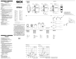
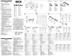
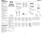
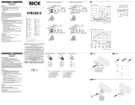
1
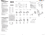
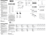
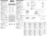
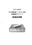
Maintenance SICK sensors are maintenance-free. We recommend doing the following regularly: - clean the external lens surfaces - check the screw connections and plug-in connections. No modifications may be made to devices. 9.9 3 (0.12) 9.7 31.5 (1.24) 28.5 (1.12) 25.4 (1.00) 9 (0.35) (0.39) D L D + 18.3 9.7 (0.72) 3 (0.12) 12 (0.47) (0.38) BKTM-xBxxxx1x 2a KTM-xBxxxx2x 2b 110 100 90 80 70 SICK AG, Erwin-Sick-Strasse 1, D-79183 Waldkirch More representatives and agencies at www.sick.com ∙ Subject to change without notice ∙ The specified product features and technical data do not represent any guarantee. Weitere Niederlassungen finden Sie unter www.sick.com ∙ Irrtümer und Änderungen vorbehalten ∙ Angegebene Produkteigenschaften und technische Daten stellen keine Garantieerklärung dar. Plus de représentations et d’agences à l’adresse www.sick.com ∙ Sujet à modification sans préavis ∙ Les caractéristiques de produit et techniques indiquées ne constituent pas de déclaration de garantie. Para mais representantes e agências, consulte www.sick.com ∙ Alterações poderão ser feitas sem prévio aviso ∙ As características do produto e os dados técnicos apresentados não constituem declaração de garantia. Altri rappresentanti ed agenzie si trovano su www.sick.com ∙ Contenuti soggetti a modifiche senza preavviso ∙ Le caratteristiche del prodotto e i dati tecnici non rappresentano una dichiarazione di garanzia. Más representantes y agencias en www.sick.com ∙ Sujeto a cambio sin previo aviso ∙ Las características y los datos técnicos especificados no constituyen ninguna declaración de garantía. 欲了解更多代表机构和代理商信息,请登录 www.sick.com ∙ 如有更改 , 不另行通知 ∙ 对所给出的产品特性和技术参数 的正确性不予保证。 その他の営業所は www.sick.com よりご覧ください ∙ 予告なし に変更されることがあります ∙ 記載されている製品機能およ び技術データは保証を明示するものではありません。 brn 1 blk 4 blu 3 wht 2 L+ 60 brn 1 1 brn QP blk blk 4 M blu 3 QN wht 2 blu wht Relative sensitivity in % Please find detailed addresses and additional representatives and agencies in all major industrial nations at www.sick.com L+ L+ 4QP 3M QN 2 QP M 50 40 30 20 0 QN 5 10 (0.20) 15 (0.39) 20 (0.59) (0.79) Sensing distance in mm (inch) 3a 1. Position background – 2. Position mark + – 3. Set switching threshold + KTM Core DEUTSCH 2011/65/EU Kontrastsensor Mit Potentiometer und Hell / Dunkelumschaltung Betriebsanleitung ® LISTED Sicherheitshinweise >> >> >> >> NFPA79 applications only These devices shall be protected by a 1A fuse suitable for 30Vdc Enclosure Type 1 Kein Sicherheitsbauteil gemäß EU-Maschinenrichtlinie. Vor der Inbetriebnahme die Betriebsanleitung lesen. Anschluss, Montage und Einstellung nur durch Fachpersonal. Gerät bei Inbetriebnahme vor Feuchte und Verunreinigung schützen. Der Kontrastsensor KTM ist ein photoelektronischer Sensor und wird zum optischen, berührungslosen Erfassen von Kontrastmarken eingesetzt. Inbetriebnahme Wartung SICK-Sensoren sind wartungsfrei. Wir empfehlen, in r egelmäßigen Abständen – die optischen Grenzflächen zu reinigen, – Verschraubungen und Steckverbindungen zu überprüfen. Veränderungen an Geräten dürfen nicht vorgenommen werden. + KTM-xB3xxxxx KTM-xB8xxxxx Tastweite Lichtfleckgröße Versorgungsspannung VS Schaltart Ausgangsstrom Imax. Schaltfrequenz Jitter Ansprechzeit Schutzart Schutzklasse Distance de détection Taille du spot lumineux Tension d‘alimentation VS Type de commutation Courant de sortie Imaxi. Fréquence de commutation Scintillement Temps de réponse Type de protection Classe de protection Alcance de detecção Tamanho do ponto de luz Tensão de força VS Tipo de ligação Corrente de saída Imáx Frequência de comutação Jitter Tempo de reação Tipo de proteção Classe de proteção 12.5 mm 2 mm x 2 mm DC 12 … 24 V 1) PNP / NPN 100 mA 2) 10 kHz 3) 25µs 50 µs 4) IP 67 12.5 mm 1 mm x 1 mm DC 12 … 24 V 1) PNP / NPN 100 mA 2) 10 kHz 3) 25µs 50 µs 4) IP 67 Ambient operating temperature Betriebsumgebungstemperatur Température ambiante Temperatura ambiente de operação -10 … +55 °C -10 … +55 °C 1) 1)Grenzwerte: 1) Valeurs limites: 12 V (-10 %) ... 24 V (+20 %). Consommation de courant sans charge < 50 mA Service dans un réseau protégév contre les courts-circuits 8 A au max. Ondulation résiduelle max. 5 VSS 2) Pour tension d‘alimentation > 24 V I max = 30 mA. Imax est la somme des courant de tous les Qn. 3) Rapport de 1:1 4) Durée du signal en charge ohmique 1) Distanza di ricezione Dimensioni zona illuminata Tensione di alimentazione VS Tipo di commutazione Corrente di uscita Imax. Frequenza di commutazione Jitter Tempo di risposta Tipo di protezione Classe di protezione Ancho de exploración Tamaño del punto de luz Tensión de alimentación VS Tipo de conmutación Corriente de salida Imáx. Frecuencia de conmutación Inestabilidad Tiempo de reacción Tipo de protección Protección clase 感应距离 検出範囲 Temperatura ambiente circostante Temperatura ambiente de servicio 工作环境-温度 使用周囲温度 1) 1) 1) 操作电流: 12 V (-10 %) ... 24 V (+20 %). 耗用电流无负荷< 50 mA 在防短路的网络里, 最大8 极限值剩余波纹度 max. 5 VSS 2) 当供电电压 > 24 V 时,最大电流 I max = 30 mA。 最大电流 Imax 是所有 Qn 的总电流。 3) 感应比:1:1 4) 电阻性负载时,传感器检测到变化时输出信号的转 换时间 1) 12 V (-10 %) ... 24 V (+20 %). Stromaufnahme ohne Last < 50 mA Betrieb in kurzschlussgeschütztem Netz max 8 A. Restwelligkeit ≤ 5 Vss 2) Bei Versorgungsspannung > 24 V, I max = 30 mA. Imax ist Summenstrom aller Qn. 3) Tastverhältnis 1:1 4) Signallaufzeit bei ohmscher Last Valores limite: 12 V (-10 %) ... 24 V (+20 %). Consumo de corrente sem carga < 50 mA Operação em rede protegida contra curto-circuitos max. 8 A Ondulação residual max. 5 VSS 2) No caso de tensão de alimentação > 24 V, I máx = 30 mA. Imáx é a corrente total de todos Qn. 3) Fator de detecção 1:1 4) Tempo de transição do sinal com carga ôhmica KTM Core 3b Am Beispiel Schaltausgang aktiv bei heller Marke mit dunklem Hintergrund H / D Umschalter auf auf „L“ (Hellschaltend) stellen. Marke in den Lichtfleck bringen Bei „+“ (Rechstanschlag) starten. Potentiometer in Richtung „–“drehen bis gelbe Anzeige LED erlischt. Poti-Position 1 merken. Anschließend Hintergrund in Lichtfleck bringen (LED leuchtet wieder) und Potentiometer weiter in Richtung „–“ drehen bis gelbe LED erneut erlischt (Position 2). Hinweis Gelbe LED entpricht immer dunkelschaltend. Bei Hellschaltend LED invers zu Schaltausgang. Bei schwachen Kontrasten wird der Einsatz des Sensors KTM Prime empfohlen. – Sensing range Light spot size Supply voltage VS Switching type Output current Imax Switching frequency Jitter Response time Enclosure rating Protection class Limit values: 12 V (-10 %) ... 24 V (+20 %). Power consumption without load < 50 mA Operation in short-circuit protected network max. 8 A ripple max. 5 Vpp 2) At supply voltage > 24 V, I max = 30 mA. Imax is consumption count of all Qn. 3) Scanning ratio 1:1 4) Signal transit time with resistive load Bestimmungsgemäße Verwendung 1 Leitungsdose spannungsfrei aufstecken und festschrauben. Für Anschluss in B gilt: brn=braun, blu=blau, blk=schwarz, wht=weiß. Ausgänge: QP oder QN. Sensor laut Anschlussschema B anschließen. 2 Sensor mit Befestigungsbohrungen an Stelle (z. B. Umlenkrolle) montieren, an der das Prüfobjekt die geringsten Seiten- und Höhenbewegungen ausführt. Dabei Tastweite beachten (vgl. technische Daten und Abbildung 2a / 2b x = Tastweite, y = relative Empfindlichkeit). Seiten- und Höhenbewegungen des Prüfobjektes durch entsprechend lange Markierungen ausgleichen. Sensor an Betriebsspannung legen (s. Typenaufdruck); Betriebsanzeige (LED grün) muss leuchten. 3 Einstellung der Schaltschwelle 3a Am Beispiel Schaltausgang aktiv bei dunkler Marke mit hellem Hintergrund H / D Umschalter auf „D“ (Dunkelschaltend) stellen. Hintergrund in den Lichtfleck bringen Bei „+“ (Rechstanschlag) starten. Potentiometer in Richtung „–“drehen bis gelbe Anzeige LED erlischt. Poti-Position 1 merken. Anschließend Marke in Lichtfleck bringen (LED leuchtet wieder) und Potentiometer weiter in Richtung „–“ drehen bis gelbe LED erneut erlischt (Position 2). Zwischen Position 1 und 2 drehen, damit Schaltschwelle optimal eingestellt ist. – 305 (12.01) 0.5 0.5 (0.02) (0.38) 31.5 (1.24) 28.5 (1.12) L (0.45) Österreich Phone +43 (0)22 36 62 28 8-0 Norge Phone +47 67 81 50 00 Polska Phone +48 22 837 40 50 România Phone +40 356 171 120 Russia Phone +7-495-775-05-30 Schweiz Phone +41 41 619 29 39 Singapore Phone +65 6744 3732 Slovenija Phone +386 (0)1-47 69 990 South Africa Phone +27 11 472 3733 South Korea Phone +82 2 786 6321/4 Suomi Phone +358-9-25 15 800 Sverige Phone +46 10 110 10 00 Taiwan Phone +886-2-2375-6288 Türkiye Phone +90 (216) 528 50 00 United Arab Emirates Phone +971 (0) 4 8865 878 USA/México Phone +1(952) 941-6780 12 (0.47) 11.4 Australia Phone +61 3 9457 0600 Belgium/Luxembourg Phone +32 (0)2 466 55 66 Brasil Phone +55 11 3215-4900 Canada Phone +1 905 771 14 44 Česká republika Phone +420 2 57 91 18 50 China Phone +86 4000 121 000 +852-2153 6300 Danmark Phone +45 45 82 64 00 Deutschland Phone +49 211 5301-301 España Phone +34 93 480 31 00 France Phone +33 1 64 62 35 00 Great Britain Phone +44 (0)1727 831121 India Phone +91–22–4033 8333 Israel Phone +972-4-6801000 Italia Phone +39 02 27 43 41 Japan Phone +81 (0)3 5309 2112 Magyarország Phone +36 1 371 2680 Nederland Phone +31 (0)30 229 25 44 25.4 (1.00) 1 Connect and secure cable receptacle tension-free. The following apply for connection in B brn=brown, blu=blue, blk=black, wht=white. Outputs: QP or QN. Connect sensor in accordance with connection diagram B. 2 Mount the sensor with mounting holes at the place (e. g. deflection roller) where the test object has the least horizontal and vertical movement. In doing so, pay attention to the scanning range (compare technical data and figure 2a / 2b x = scanning range, y = relative sensitivity). Align the horizontal and vertical movements of the test object using correspondingly long markings. Connect sensor to operating voltage (see type label); status indicator (green LED) must light up. Setting the switching threshold 3 3a Using the example of active switching output with dark mark and light background Set H / D switch to “D” (dark-switching). Bring the background into the light spot. Start at “+” (right-hinged). Turn the potentiometer in direction “–” until the yellow LED goes out. Note potentiometer position 1. Then bring the mark into the light spot (LED lights up again) and continue to turn the potentiometer in direction “–” until the yellow LED goes out again (position 2). Turn between position 1 and 2 to ensure that the optimum switching threshold is set. Using the example of active switching output with light mark 3b and dark background Set H / D switch to “L” (light-switching). Bring the mark into the light spot. Start at “+” (right-hinged). Turn the potentiometer in direction “–” until the yellow LED goes out. Note potentiometer position 1. Then bring the background into the light spot (LED lights up again) and continue to turn the potentiometer in direction “–” until the yellow LED goes out again (position 2). Note Yellow LED always corresponds to dark-switching. Light-switching LED inverse to switching output. For weak contrasts, we recommend using the KTM Prime sensor. (0.38) Starting Operation Ø 7 (0.28) (0.39) 9.7 The KTM contrast sensor is an photoelectronic sensor for the optical, non-contact detection of contrast marks. 0.5 (0.02) 9 KTM Core Correct use 9.9 (0.35) -------------------------------------------------------- 8015849.YD55 0515 COMAT ------------------------------------------------------ BZ int43 >> Not a safety component in accordance with EU Machinery Directive. >> Read the operating instructions before commissioning. >> Connection, mounting, and setting is only to be performed by trained specialists. >> When commissioning, protect the device from moisture and contamination. (0.02) Safety notes 21 (0.83) 0.5 21 (0.83) (0.02) A 5.6 (0.22) ENGLISH Contrast sensor With potentiometer and light / dark switching Operating instruction Valori limite: 12 V (-10 %) ... 24 V (+20 %). Assorbimento di corrente senza carico < 50 mA Funzionamento in rete con protezione dai cortocircuiti max. 8 A ondulazione residua max. 5 VSS 2) Per una tensione di alimentazione> 24 V, I max = 30 mA. Imax è la corrente cumulativa di tutti i Qn. 3) Rapporto di lavoro 1:1 4) Tempo di continuare de segnale a resistenza ohmica Valores límite: 12 V (-10 %) ... 24 V (+20 %). Consumo de corriente sin carga < 50 mA Funcionamiento en la red protegida contra cortocircuito, max. 8 A ondulación residual max. 5 VSS 2) Tensión de alimentación > 24 V, I máx = 30 mA. Imáx es la corriente total de todos los Qn. 3) Relación de exploración 1:1 4) Duración de la señal con carga óhmica 光斑尺寸 供給電圧 电源电压 VS 开关类型 供給電圧 VS スイッチ出力タイプ 输出电流Imax. 最大出力電流 Imax. スイッチング頻度 开关频率 抖动 触发时间 保护种类 保护级别 ステップ偏差 (Jitter) 応答時間 保護等級 KTM-xB3xxxxx KTM-xB8xxxxx 12.5 mm 2 mm x 2 mm DC 12 … 24 V 1) PNP / NPN 100 mA 2) 10 kHz 3) 25µs 50 µs 4) IP 67 12.5 mm 1 mm x 1 mm DC 12 … 24 V 1) PNP / NPN 100 mA 2) 10 kHz 3) 25µs 50 µs 4) IP 67 -10 … +55 °C -10 … +55 °C 保護クラス 限界値: 12 V (-10 %) ... 24 V (+20 %). 負荷なしでの電流消費 < 50 mA 短絡防止回路での動作 最大 8 A、 残留リップル最大 5 VSS 2) 電源電圧が> 24 V の場合、I max = 30 mA。 Imax はすべての Qn の全電流。 3) 検出比 1:1 4) 抵抗負荷における信号遷移時間 FRANÇAIS Détecteur de contraste Avec le potentiomètre et la commutation claire / sombre Manuel d’utilisations Remarques relatives à la sécurité >> Il ne s’agit pas d’un composant de sécurité conformément à la Directive CE sur les machines. >> Lire le manuel d’utilisation avant la mise en service. >> Faire effectuer le raccordement, le montage et le réglage uniquement par un personnel spécialisé. >> Protéger l’appareil de l’humidité et des impuretés lors de la mise en service. PORTUGUÊS Sensor de contraste Com potenciômetro e comutação por luz / sombra Instruções de operação Notas de segurança >> Os componentes de segurança não se encontram em conformidade com a Diretiva Europeia de Máquinas. >> Ler as instruções de operação antes da colocação em funcionamento. >> A conexão, a montagem e o ajuste devem ser executados somente por pessoal técnico qualificado. >> Durante o funcionamento, manter o aparelho protegido contra impurezas e umidade. ITALIANO Sensore di contrasto Con potenziometro e commutazione chiaro / scuro Struzioni d’uso Avvertenze sulla sicurezza >> Nessun componente di sicurezza conformemente alla direttiva macchine UE. >> Prima della messa in funzione leggere le istruzioni d’uso. >> Allacciamento, montaggio e regolazione solo a cura di personale tecnico specializzato. >> Alla messa in funzione proteggere l’apparecchio dall’umidità e dalla sporcizia. Utilisation conforme Especificações de uso Impiego conforme agli usi previsti Le capteur de contrastes KTM est un capteur photoélectronique qui sert à la détection visuelle de repères sans contact direct. O sensor de contraste KTM é um sensor photoleletrônico utilizado para a detecção óptica e sem contato de marcas de contraste. Il sensore di contrasto KTM è un sensore photoelettronico utilizzato per il rilevamento ottico senza contatto di marchi in contrasto. Mise en service Colocação em funcionamento Messa in funzione 1 Enficher la boîte à conducteurs sans aucune tension et la visser. Pour le raccordement dans B on a : brn = brun, blu = bleu, blk = noir, gra = gris, wht = blanc. Sorties : QP o QN. Brancher le capteur conformément au schéma de raccordement B. 2 Installer le capteur, muni de trous de fixation, à l’endroit (par ex. poulie de renvoi) où l’objet à examiner exécute les mouvements latéraux et verticaux les plus faibles. Ce faisant, tenir compte de la portée de détection (cf. les caractéristiques techniques et l‘illustration 2a / 2b x = portée de détection, y = sensibilité relative). Compenser les mouvements latéraux et verticaux de l’objet à examiner au moyen de repères de longueur appropriée. Apposer la tension de fonctionnement au capteur (cf. fiche signalétique) ; le témoin de fonctionnement (LED verte) doit être allumé. 3 Réglage du seuil de commutation 3a avec comme exemple une sortie de commutation active lors d’un repère sombre sur arrière-plan clair Mettre la commutation H / D « D » (commutation sombre). Amener l‘arrière-plan dans le spot lumineux. Démarrer au niveau du « + » (butée à droite). Faire tourner le potentiomètre en direction du « – » jusqu‘à ce que le témoin jaune s‘éteigne. Repérer la position Poti 1. Puis amener le repère dans le spot lumineux (le témoin est à nouveau allumé) et faire tourner le potentiomètre en direction du « – » jusqu‘à ce que le témoin jaune s‘éteigne à nouveau (position 2). Ajuster entre les positions 1 et 2 pour régler le seuil de commutation de manière optimale. 3b Avec comme exemple une sortie de commutation active lors d’un repère clair sur arrière-plan sombre Mettre la commutation H / D sur « D » (commutation claire). Amener le repère dans le spot lumineux. Démarrer au niveau du « + » (butée à droite). Faire tourner le potentiomètre en direction du « – » jusqu‘à ce que le témoin jaune s‘éteigne. Repérer la position Poti 1. Puis amener l‘arrière-plan dans le spot lumineux (le témoin est à nouveau allumé) et faire tourner le potentiomètre en direction du « – » jusqu‘à ce que le témoin jaune s‘éteigne à nouveau (position 2). Remarque Le témoin jaune indique toujours une commutation sombre. En cas de commutation claire, le témoin est à l‘inverse de la sortie de commutation. En présence de contrastes faibles, il est recommandé d‘utiliser le capteur KTM Prime. Maintenance Les capteurs SICK ne nécessitent aucune maintenance. Nous vous recommandons de procéder régulièrement - au nettoyage des surfaces optiques - au contrôle des liaisons vissées et des connexions. Ne procédez à aucune modification sur les appareils. 1 Enfiar a caixa de cabos sem torções e aparafusá-la. Para a ligação elétrica em B é: brn = marron, blu = azul, blk = preto, gra = cinzento, wht = branco. Saídas: QP e QN. Conectar o sensor de acordo com o esquema de conexão B. 2 Montar o sensor executando perfurações no lugar (por ex. rolo de inversão), em que o objeto de controle executa os menores movimentos laterais e de elevação. Observar a distância de detecção (cf. dados técnicos e figura 2a / 2b x = distância de detecção, y = sensibilidade relativa). Compensar os movimentos laterais e de elevação do objeto de controle através de marcações de comprimento adequado. Ligar o sensor à tensão operacional (ver especificações de tipo); o indicador de operação (LED verde) tem que acender. 3 Ajuste do limiar de comutação 3a No exemplo, saída de comutação ativa com marca escura e fundo claro Colocar comutador H / D para “D” (comutação para escuro). Colocar o fundo no ponto de luz. Iniciar com “+” (batente direito). Girar o potenciômetro na direção “–” até o indicador LED amarelo apague. Notar a posição do potenciômetro 1. Em seguida, colocar a marca no ponto de luz (o LED acende novamente) e continuar a girar o potenciômetro na direção “–” até que o LED amarelo apague novamente (posição 2). Girar entre a posição 1 e 2 para obter o melhor ajuste do limiar de comutação. 3b No exemplo, saída de comutação ativa com marca clara e fundo escuro Colocar comutador H / D para “L” (comutação para claro). Colocar a marca no ponto de luz. Iniciar com “+” (batente direito). Girar o potenciômetro na direção “–” até o indicador LED amarelo apague. Notar a posição do potenciômetro 1. Em seguida, colocar o fundo no ponto de luz (o LED acende novamente) e continuar a girar o potenciômetro na direção “–” até que o LED amarelo apague novamente (posição 2). Aviso O LED amarelo corresponde sempre a comutação por sombra. Com comutação por luz, LED inverso à saída de comutação. Para contrastes fracos, recomenda se a utilização do sensor KTM Prime. Manutenção Os sensores SICK são isentos de manutenção. Recomendamos que se efetue em intervalos regulares - uma limpeza das superfícies ópticas - uma verificação das conexões roscadas e dos conectores. Não são permitidas modificações no aparelho. 1 Inserire scatola esente da tensione e avvitare stringendo. Per collegamento B osservare: brn = marrone, blu = blu, blk = nero, gra = grigio, wht = bianco. Uscite: QPNP o QNPN. Collegare il sensore secondo lo schema dei collegamenti B. 2 Montare il sensore con i fori di fissaggio nel punto (ad es. carrucola di rinvio) in cui l’oggetto effettua meno movimenti orizzontali e verticali. Osservare l‘ampiezza di rilevamento (cfr. dati tecnici e figura 2a / 2b x = ampiezza di rilevamento, y = sensibilità relativa). Compensare i movimenti orizzontali e verticali dell’oggetto tramite demarcazioni di lunghezza adeguata. Applicare il sensore alla tensione d‘esercizio (v. stampigliatura del tipo); l‘indicatore di funzionamento (LED verde) deve essere acceso. 3 Impostazione della soglia di commutazione 3a Ad esempio, uscita di commutazione attiva con marchio scuro e sfondo chiaro Commutatore H / D impostato su «D» (commutazione scuro). Posizionare lo sfondo nella zona illuminata. Partire con «+» (battuta destra). Ruotare il potenziometro in direzione «–» fino allo spegnimento dell‘indicatore LED giallo. Notare la posizione del potenziometro 1. Poi posizionare il marchio nella zona illuminata (il LED si riaccende) e ruotare ulteriormente il potenziometro in direzione «–» fino al successivo spegnimento dell‘indicatore LED giallo (posizione 2). Tra le posizioni 1 e 2, effettuare una rotazione per regolare la soglia di commutazione in modo ottimale. 3b Ad esempio, uscita di commutazione attiva con marchio chiaro e sfondo scuro Commutatore H / D impostato su «L» (commutazione chiaro). Posizionare il marchio nella zona illuminata. Partire con «+» (battuta destra). Ruotare il potenziometro in direzione «–» fino allo spegnimento dell‘indicatore LED giallo. Notare la posizione del potenziometro 1. Poi posizionare lo sfondo nella zona illuminata (il LED si riaccende) e ruotare ulteriormente il potenziometro in direzione «–» fino al successivo spegnimento dell‘indicatore LED giallo (posizione 2). Indicazione Il LED giallo indica sempre una commutazione «scura». Per una commutazione «chiara», LED inverso rispetto all‘uscita di commutazione. Se il contrasto è debole, è consigliabile l‘impiego del sensore KTM Prime. Manutenzione I sensori SICK non hanno bisogno di manutenzione. Consigliamo di pulire in intervalli regolari - le superfici limite ottiche - verificare i collegamenti a vite e gli innesti a spina. Non è consentito effettuare modifiche agli apparecchi. ESPAÑOL Sensor de contraste Conmutación de claro / oscuro con potenciómetro. Instrucciones de servicio Indicaciones de seguridad >> No se trata de un componente de seguridad según la Directiva de máquinas de la UE. >> Lea las instrucciones de servicio antes de efectuar la puesta en funcionamiento. >> La conexión, el montaje y el ajuste deben ser efectuados exclusivamente por técnicos especialistas. >> Proteja el equipo contra la humedad y la suciedad durante la puesta en funcionamiento. Uso conforme a lo previsto El sensor de contraste KTM es un sensor photoelectrónico que se utiliza para detectar marcas de contraste de forma óptica y sin contacto. Puesta en funcionamiento 1 Insertar y atornillar bien la caja de conexiones sin tensión. Para conectar en B: brn = marrón, blu = azul, blk = negro, gra = gris, wht = blanco. Salidas: QPNP y QNPN. Conecte el sensor según muestra el esquema de conexión B. 2 Montar el sensor con las perforaciones de fijación en el lugar (p. e. polea de reenvío) donde los objetos a controlar ejecuten el menor movimiento lateral y de altura. Observar en este proceso el ancho de exploración (compare los datos técnicos e imagen 2a / 2b x = ancho de exploración, y = sensibilidad relativa). Compensar los movimientos laterales y de altura de los objetos a controlar mediante marcas correspondientemente largas. Conecte el sensor a la tensión de servicio (consulte los datos característicos); el indicador de servicio (LED verde) debe iluminarse. 3 Ajuste del umbral de conmutación 3a En el ejemplo, salida conmutada activa con marca oscura y fondo claro Ajuste el conmutador H / D en posición «D» (conmutación en oscuro). Coloque el fondo en el punto de luz. Empiece en «+» (tope derecho). Gire el potenciómetro en dirección «–» hasta que se apague el indicador LED amarillo. Marque la posición 1 del potenciómetro. A continuación, coloque la marca en el punto de luz (el LED volverá a iluminarse) y siga girando el potenciómetro en dirección «–» hasta que vuelva a apagarse el LED amarillo (posición 2). Gire el potenciómetro entre las posiciones 1 y 2 para ajustar el umbral de conmutación de forma óptima. 3b En el ejemplo, salida conmutada activa con marca clara y fondo oscuro Ajuste el conmutador H / D en posición «L» (conmutación en claro). Coloque la marca en el punto de luz. Empiece en «+» (tope derecho). Gire el potenciómetro en dirección «–» hasta que se apague el indicador LED amarillo. Marque la posición 1 del potenciómetro. A continuación, coloque el fondo en el punto de luz (el LED volverá a iluminarse) y siga girando el potenciómetro en dirección «–» hasta que vuelva a apagarse el indicador LED amarillo (posición 2). Indicación El LED amarillo siempre hace referencia a la conmutación en oscuro. En caso de conmutación en claro, el LED se corresponde inversamente a la salida conmutada. Si se trabaja con contrastes débiles, se recomienda usar el sensor KTM Prime. Mantenimiento Los sensores SICK no requieren mantenimiento. En intervalos regulares, recomendamos - limpiar las superficies ópticas externas - comprobar las uniones roscadas y las conexiones. No se permite realizar modificaciones en los aparatos. 中文 日本語 色标传感器 带电位计和亮 / 暗通切换功能 操作规程 コントラストセンサ ポテンショメータおよびライト / ダークオンスイッチ付き 取扱説明書 安全须知 >> 本设备非欧盟机械指令中定义的安全部件。 >> 调试前请阅读操作规程。 >> 仅允许由专业人员进行接线、安装和设置。 >> 调试时应防止设备受潮或脏污。 正确使用须知 对比度传感器 KTM 是一种光电传感器,用于非接触式光学检测。 操作步骤 1 在不通电的情况下插上电缆插座并拧紧。 B 接口对应如下:brn = 棕色,blu = 蓝色,blk = 黑色,wht = 白色。 输出端:QP 或 QN。 首先,根据连接图 B 连接传感器。 2 通过固定孔将传感器安装在相应位置(例如换向辊),测试对象在此位 置处的侧向和高度方向移动最少。 此时注意感应距离(对比技术数据和插图 2a / 2b x = 感应距离, y = 相对敏感度)。 通过适当长度的标记对测试对象侧向和高度方向的移动进行调节。 按工作电压(参见铭牌参数)接通传感器,状态指示灯 (绿色LED) 会亮起。 3 设置开关阈值 3a 例如,在深色标记和浅色背景下激活开关输出 将 H / D 转换开关调至“D”(暗通)。 将背景移入光斑中。 从“+”(右侧极限位置)处开始。 将电位计沿“–”方向旋转,直到黄色 LED 指示灯熄灭。 标记电位计位置 1。 然后,将色标移到光斑中(LED 再次亮起),并继续将电位计沿“–”方向 旋转,直到黄色 LED 重新熄灭(位置 2)。 在位置 1 和 2 之间旋转,以便对开关阈值进行最佳设置。 3b 例如,在浅色标记和深色背景下激活开关输出 将 H / D 转换开关置于“L”(亮通)。 将标记移入光斑中。 从“+”(右侧极限位置)处开始。 将电位计沿“–”方向旋转,直到黄色 LED 指示灯熄灭。 标记电位计位置 1。 然后,将背景移入光斑中(LED 再次亮起),并继续将电位计沿“–”方向 旋转,直到黄色 LED 重新熄灭(位置 2)。 提示 黄色 LED 始终与关灯动作一致。 亮通设置时 LED 与开关输出端相反。 对比度低时建议使用 KTM Prime 传感器。 保养 SICK 传感器无需维护。 我们建议定期进行以下操作: - 清洁镜头检测面 - 检查螺丝接头和插头连接。 请勿对设备进行任何改装。 安全上の注意事項 >> 本製品は EU 機械指令の要件を満たす安全コンポーネントではありま せん。 >> 使用を開始する前に取扱説明書をお読みください。 >> 接続、取付けおよび設定できるのは専門技術者に限ります。 >> 装置を使用開始する際には、濡れたり汚れたりしないように保護して ください。 使用目的 コントラストスキャナ KTM は光電センサで、対象物を光学技術により非接 触で検知するための装置です。 使用開始 1 ーブルプラグをケーブルに張力がかからないように差し込み、ネジ ケ 止めします。 B の接続:brn = 茶、blau = 青、blk = 黒、wht = 白 出力:QP または QN センサを接続図 B に従って接続します。 2 センサの固定用ボアのある方を、検査対象物の上下左右の動きが最も 小さい場所 (例えば偏向ローラー) に取付けます。 その際検出範囲にご注意ください (技術仕様および図 2a / 2b を参照。 x = 検出範囲、y = 相対感度) 検出対象物の上下左右の動きを、適切な長さのマークで補正します。 を参照して、配線を接続します。センサに作動電圧を供給すると (型式ラベル参照)、表示灯 (LED 緑) が点灯するはずです。 3 スイッチング閾値の設定 3a 例、スイッチング出力が作動しており、暗色のマークと明色の背景の 場合 H / D 切り替えスイッチを「D」 (ダークオン) にします。 背景を光点に移動させます。 「+」 (右極限) で始動させます。 黄色の LED 表示が消灯するまで、ポテンショメーターを「–」の方向に 回します。 ポテンショメータ位置 1 を覚えておきます。 続いてマークを光点内に移動させ(LED が再び点灯)、黄色い LED 表示 が再び消灯するまでポテンショメータをさらに「–」方向に回します。 イッチング閾値が最適な状態に設定されるように、位置 1 と 2 の間 ス で回します。 3b 例、スイッチング出力が作動しており、明色のマークと暗色の背景の 場合 H / D 切り替えスイッチを「L」(ライトオン)にします。 マークを光点に移動します。 「+」 (右極限) で始動させます。 黄色の LED 表示が消灯するまで、ポテンショメーターを「–」の方向に 回します。 ポテンショメータ位置 1 を覚えておきます。 続いて背景を光点内に移動させ(LED が再び点灯)、黄色い LED 表示 が再び消灯するまでポテンショメータをさらに「–」方向に回します。 注意事項 黄色い LED 表示は常にダークオンです。 ライトオンの場合は、LED はスイッチング出力の逆です コントラストが低い場合には、センサ KTM Prime の使用を推奨します。 メンテナンス SICK のセンサはメンテナンス不要です。 推奨する定期的な保全作業 - レンズ境界面の清掃 - ネジ締結と差込み締結の点検 デバイスに変更を加えることは一切禁止されています。