1
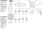
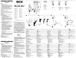
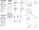
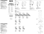
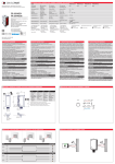
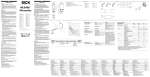
Installation instructions 4 The G6 housing can be fitted using the fitting screws supplied. Take the maximum tightening torque from the corresponding drawing. Maintenance SICK light barriers are maintenance-free. We recommend doing the following regularly: - Clean the external lens surfaces. - Check the screw connections and plug-in connections. No modifications may be made to devices. DEUTSCH Reflexions-Lichtschranke mit sichtbarem Rotlicht und Polarisationsfilter Betriebsanleitung Sicherheitshinweise >> >> >> >> Kein Sicherheitsbauteil gemäß EU-Maschinenrichtlinie. Vor der Inbetriebnahme die Betriebsanleitung lesen. Anschluss, Montage und Einstellung nur durch Fachpersonal. Gerät bei Inbetriebnahme vor Feuchte und Verunreinigung schützen. Bestimmungsgemäße Verwendung Die GL6 ist eine optoelektronische Reflexionslichtschranke und wird zum optischen, berührungslosen Erfassen von Sachen, Tieren und Personen eingesetzt. Sender und Empfänger sind in einem Gehäuse untergebracht. Zur Funktion wird ein Reflektor benötigt, der das Licht an den Empfänger zurück reflektiert. Wird der Lichtstrahl durch ein Objekt unterbrochen so führt es zu einem Schalten des Ausgangs. GL6G ist eine optoelektronische Reflexionslichtschranke mit Einstellungs möglichkeit der Schaltschwelle zur Erfassung transparenter Objekte (20 % Signalabschwächung). Inbetriebnahme 1 Auswahl des Reflektors in Abhängigkeit der benötigten Reichweite (siehe Diagramm Schaltabstände). 2 Nur bei den Steckerversionen: Leitungsdose spannungsfrei aufstecken und festschrauben. Nur bei den Versionen mit Anschlussleitung: Für Anschluss gilt: brn = braun, blu = blau, blk = schwarz, wht = weiß. 3 Nach Anschluss der Betriebsspannung leuchtet die grüne LED. Montage des Reflektors gegenüber der Lichtschranke. Durch horizontales und vertikales Schwenken wird der Sensor optimal auf den Reflektor ausgerichtet. Dabei ist kein Objekt zwischen Sensor und Reflektor. Bei optimaler Ausrichtung leuchtet die gelbe LED konstant. Bei ungenauer Ausrichtung oder nicht ausreichender Reserve blinkt die gelbe LED. Nach durchgeführter Ausrichtung ein Objekt in den Strahlengang führen um die Funktion zu überprüfen. GL6: Gelbe LED erlischt und Schaltausgang wechselt. GL6G und GL6 mit Potentiometer: Gelbe LED muss erlöschen. Ist dies nicht der Fall, Empfindlichkeit so lange verändern, bis Schaltschwelle korrekt eingestellt ist. PNP (Last → M): Objekt wird erkannt, Ausgang (Q) HIGH NPN (Last → L+): Objekt wird erkannt, Ausgang (Q) LOW 25.4 (1.00) 7.6 (0.30) Österreich Phone +43 (0)22 36 62 28 8-0 Norge Phone +47 67 81 50 00 Polska Phone +48 22 837 40 50 România Phone +40 356 171 120 Russia Phone +7-495-775-05-30 Schweiz Phone +41 41 619 29 39 Singapore Phone +65 6744 3732 Slovenija Phone +386 (0)1-47 69 990 South Africa Phone +27 11 472 3733 South Korea Phone +82 2 786 6321/4 Suomi Phone +358-9-25 15 800 Sverige Phone +46 10 110 10 00 Taiwan Phone +886-2-2375-6288 Türkiye Phone +90 (216) 528 50 00 United Arab Emirates Phone +971 (0) 4 8865 878 USA/México Phone +1(952) 941-6780 Maximum torque 0.4 Nm GL6(G) 0.5 (0.02) L D 10 L D PL20A 11.4 3 (0.12) 9.7 (0.45) 1 Select the reflector based on the required sensing range (see Operating distances diagram). 2 Only for connector versions: Plug in the cable socket without current applied and screw it tight. Only for versions with connecting cable: The following connections apply: brn = brown, blu = blue, blk = black, wht = white. 3 The green LED lights up after connecting the operating voltage. Installation of the reflector opposite the retro-reflective sensor. The sensor is optimally aligned with the reflector by swiveling the sensor horizontally and vertically. There should be no objects between the sensor and reflector. When aligned correctly, the yellow LED lights up continuously. If not aligned correctly or there is not adequate reserve, the yellow LED flashes. After alignment is complete, move an object into the optical path to test its function. GL6: The yellow LED goes out and the switching output changes. GL6G and GL6 with potentiometer: Yellow LED must switch off. If this does not happen, adjust the sensitivity until the switching threshold is correctly adjusted. PNP (load → M): Object is detected, Output (Q) HIGH NPN (load → L+): Object is detected, Output (Q) LOW Australia Phone +61 3 9457 0600 Belgium/Luxembourg Phone +32 (0)2 466 55 66 Brasil Phone +55 11 3215-4900 Canada Phone +1(952) 941-6780 Ceská Republika Phone +420 2 57 91 18 50 China Phone +852-2763 6966 Danmark Phone +45 45 82 64 00 Deutschland Phone +49 211 5301-301 España Phone +34 93 480 31 00 France Phone +33 1 64 62 35 00 Great Britain Phone +44 (0)1727 831121 India Phone +91–22–4033 8333 Israel Phone +972-4-6801000 Italia Phone +39 02 27 43 41 Japan Phone +81 (0)3 3358 1341 Magyarország Phone +36 1 371 2680 Nederlands Phone +31 (0)30 229 25 44 21 (0.83) 9.7 Starting operation GL6(G) Functional reserve (650 nm) 100 (0.38) The GL6 is an photoelectric retro-reflective sensor for the optical, noncontact detection of objects, animals and persons. The sender and receiver are integrated into a single housing unit. To function, a reflector is required that reflects the light back to the receiver. If the light beam is interrupted by an object, it causes the output to switch. GL6G is a photoelectric retro-reflective sensor with which it is possible to set the switching threshold to record transparent objects (20 % signal decrease). --------------------------------------------------------------------- 8015350 0912 CV -------------------------------------------------------------------- (0.38) 1 12 18.3 0 (0.47) (0.72) Reflective tape „Diamond Grade“ 2.0 0 (78.7) PL80A P250 PL40A 4.0 6.0 (157.5) (236.2) 8.0 (315.0) Distance in mm (inch) B GL6(G)-P / N4xxx GL6(G)-P / N6xxx GL6(G)-P / N7xxx GL6(G)-P / N3xxx GL6(G)-P / N5xxx 3a 3b GL6(G) GL6G – + SICK AG, Erwin-Sick-Strasse 1, D-79183 Waldkirch Please find detailed addresses and additional representatives and agencies in all major industrial nations at www.sick.com BZ int38 Correct use 0.5 (0.02) Safety notes >> Not a safety component in accordance with EU Machinery Directive. >> Read the operating instructions before commissioning. >> Connection, mounting, and setting is only to be performed by trained specialists. >> When commissioning, protect the device from moisture and contamination. 2 1 GL6(G) 31.5 (1.24) A Photoelectric retro-reflective sensor with visible red light and polarization filter Operating Instructions 28.5 (1.12) ENGLISH More representatives and agencies at www.sick.com ∙ Subject to change without notice ∙ The specified product features and technical data do not represent any guarantee. Weitere Niederlassungen finden Sie unter www.sick.com ∙ Irrtümer und Ä nderungen vorbehalten ∙ Angegebene Produkteigenschaften und technische Daten stellen keine Garantieerklärung dar. Plus de représentations et d’agences à l’adresse www.sick.com ∙ Sujet à modification sans préavis ∙ Les caractéristiques de produit et techniques indiquées ne constituent pas de déclaration de garantie. Para mais representantes e agências, consulte www.sick.com ∙ Alterações poderão ser feitas sem prévio aviso ∙ As características do produto e os dados técnicos apresentados não constituem declaração de garantia. Altri rappresentanti ed agenzie si trovano su www.sick.com ∙ Contenuti soggetti a modifiche senza preavviso ∙ Le caratteristiche del prodotto e i dati tecnici non rappresentano una dichiarazione di garanzia. Más representantes y agencias en www.sick.com ∙ Sujeto a cambio sin previo aviso ∙ Las características y los datos técnicos especificados no constituyen ninguna declaración de garantía. 欲了解更多代表机构和代理商信息,请登录 www.sick.com ∙ 如有更改, 不另行通知 ∙ 对所给出的产品特性和技术参数 的正确性不予保证。 その他の営業所は www.sick.com よりご覧ください ∙ 予告なし に変更されることがあります ∙ 記載されている製品機能およ び技術データは保証を明示するものではありません。 brn 1 L+ blu 3 M blk 4 Q wht 2 NC brn 1 L+ blu 3 M blk 4 Q wht 2 NC GL6(G)-E/F4xxx GL6(G)-E/F6xxx GL6(G)-E/F7xxx brn blu blk 1 L+ 3 M 4 Q GL6(G)-E/F2xxx brn blu blk 1 L+ 3 M 4 Q GL6(G)-P/N1xxx L L DD L D 4 GL6(G) L D L D Q (PNP) Q (NPN) brn 1 blk 4 ® LISTED wht 2 blu 3 L+ Q Q M brn 1 blk 4 wht 2 blu 3 L+ brn L+ brn 1 Q blk Q blu Q wht Q blk 3 M 4 Q M blu M L+ Q (NPN) Q (PNP) Montagehinweise 4 Das G6-Gehäuse kann mit den mitgelieferten Montageschrauben fixiert werden. Maximales Anzugsdrehmoment ist der entsprechenden Zeichnung zu entnehmen. Wartung SICK-Lichtschranken sind wartungsfrei. Wir empfehlen, in r egelmäßigen Abständen: – die optischen Grenzflächen zu reinigen. – Verschraubungen und Steckverbindungen zu überprüfen. Veränderungen an Geräten dürfen nicht vorgenommen werden. 8015350_BTA_GL6-GL6G_2012_09_14.indd 1 18.09.2012 14:02:23 GL6 GL6G Sensing range RW max. (with PL80A reflector) Light spot diameter / distance Supply voltage VS Output current Imax. Switching frequency Response time Enclosure rating Protection class Reichweite RW max. (mit Reflektor PL80A) Lichtfleckdurchmesser / Entfernung Versorgungsspannung UV Ausgangsstrom Imax. Schaltfolge max. Ansprechzeit Schutzart Schutzklasse Portée RW max. (avec réflecteur PL80A) Diamètre de la tache lumineuse / Distance Tension d‘alimentation UV Courant de sortie Imax. Fréquence max. Temps de réponse Type de protection Classe de protection Alcance da luz RW max. (com o refletor PL80A) Diâmetro do ponto de luz / distância Tensão de força UV Corrente de saída Imax. Sequência max. de sinais Tempo de reação Tipo de proteção Classe de proteção 0.03 … 7.2 m 8 mm / 350 mm DC 10 … 30 V 1) 100 mA 2) Typ. 1 kHz 3) < 0.625 ms 4) IP 67 0.03 … 7.2 m 8 mm / 350 mm DC 10 … 30 V 1) 100 mA 2) Typ. 1 kHz 3) < 0.625 ms 4) IP 67 Circuit protection Ambient operating temperature Schutzschaltungen Betriebsumgebungstemperatur Circuits de protection Température ambiante Circuitos protetores Temperatura ambiente de operação A, B, D 5) -25 … +55 °C A, B, D 5) -25 … +55 °C 6) 1) 1) 1) 1) Valores limiares, operação em rede protegida contra curto-circuitos max. 8 A 6) B = Entradas e saídas protegidas con tra polaridade inversa D = Saídas protegidas contra sobrecorrente e curto-circuito. Estabilidade da temperatura após o ajuste + / - 10 °C GL6 GL6G 0.03 … 7.2 m 8 mm / 350 mm DC 10 … 30 V 1) 100 mA 2) Typ. 1 kHz 3) < 0.625 ms 4) IP 67 0.03 … 7.2 m 8 mm / 350 mm DC 10 … 30 V 1) 100 mA 2) Typ. 1 kHz 3) < 0.625 ms 4) IP 67 A, B, D 5) -25 … +55 °C A, B, D 5) -25 … +55 °C 6) Limit values, operation in short-circuit protected network max. 8 A 2)When U > 24 V, I A max. = 50 mA. V 3) With light / dark ratio 1:1 4) Signal transit time with resistive load 5) A = V connections reversepolarity protected S 6) B = inputs and output reverse-polarity protected D = outputs overcurrent and short-circuit protected Temperature stability following adjustment + / - 10 °C Grenzwerte, Betrieb in kurzschlussgeschütztem Netzwerk max. 8 A Bei UV > 24 V, I A max. = 50 mA Mit Hell- / Dunkelverhältnis 1:1 Signallaufzeit bei ohmscher Last 5) A = U -Anschlüsse verpolsicher V B = Ein- und Ausgänge verpolsicher D = Ausgänge überstrom- und kurzschlussfest 6) Temperaturstabilität nach Einstellung + / - 10 °C 2) 3) 4) Portata RW massima (con riflettore PL80A) Diametro punto luminoso / distanza Tensione di alimentazione UV Corrente di uscita Imax. Sequenza signali max. Tempo di risposta Tipo di protezione Classe di protezione Alcance RW max. (con reflector PL80A) Diámetro / distancia de mancha de luz Tensión de alimentación UV Corriente de salida Imax. Secuencia de señales max. Tiempo de reacción Tipo de protección Protección clase Commutazioni di protezione Temperatura ambiente circostante 1) 6) Valeurs limites, fonctionnement en réseau protégé contre les courts-circuits, 8 A max. En cas de UV > 24 V, I A max. = 50 mA. Pour un rapport clair / sombre 1:1 Durée du signal en charge ohmique A = Raccordements UV protégés contre B = entrée et sortie sécurisées en mat. de polarisation D = sortie résistant au courant de surcharge et aux courts-circuits 6) Stabilité de la température à + / - 10 °C après réglage 2) 3) 4) 5) 2)Com U > 24 V, I A max. = 50 mA. V 3) Com uma relação luminoso / escuro de 1:1 4) Tempo de transição do sinal com carga ôhmica 5) A = Conexões U protegidas contra inversão de polos V 有效感距 RW(带反射器 PL80A) 検出距離範囲 RW、最大値 (リフレクタ PL80A 使用) 光点直径 / 距离 スポット径 / 距離 电源电压UV 供給電圧 UV 输出电流 Imax. 最大出力電流 Imax. 信号流 max. 触发时间 切替順序 max. 応答時間 保护种类 保護等級 保护级别 保護クラス Circuitos de protección Temperatura ambiente de servicio 保护电路 保護回路 工作环境-温度 使用周囲温度 Funzionamento in rete protetta da cortocircuiti max. 8 A 1) Valores límite, funcionamiento en red protegida contra cortocircuito max. 8 A. 1) 1) B = entrate e uscite protette da polarità inversa D = uscite protette da sovracorrente e da cortocircuito Resistenza termica dopo impostazione + / - 10 °C 6) B = Entradas y salidas protegidas contra polarización incorrecta D = Salidas a prueba de sobrecorriente y cortocircuitos Estabilidad de temperatura tras el ajuste + / - 10 °C 在具备短路保护的电网中运行时,极限值最大 8 A 当 UV > 24 V, I A max. = 50 mA. 亮 / 暗比 1:1 电阻性负载时,传感器检测到变化时输出信号的转换时间 5) A = U -接头防反接 V B = 具有反极性保护的输入端和输出端 D = 抗过载电流和抗短路输出端 6) 设定之后的温度稳定性 + / - 10 °C 2)Con U > 24 V, I A max. = 50 mA V 3) Con relatio chiaro / scuro 1:1 4) Tempo di continuare de segnale a resistenza ohmica 5) A = U -collegamenti con protez. contro inversione di poli V 2)Con U > 24 V, I A max. = 50 mA. V 3) Con una relación claro / oscuro de 1:1 4) Duración de la señal con carga óhmica 5) A = Conexiones U a prueba de inversión de polaridad V FRANÇAIS Barrière à réflexion avec faisceau rouge visible et filtre de polarisation Manuel d’utilisations Remarques relatives à la sécurité >> Il ne s’agit pas d’un composant de sécurité conformément à la Directive CE sur les machines. >> Lire le manuel d’utilisation avant la mise en service. >> Faire effectuer le raccordement, le montage et le réglage uniquement par un personnel spécialisé. >> Protéger l’appareil de l’humidité et des impuretés lors de la mise en service. 2) 3) 4) PORTUGUÊS Fotocélula com reflexão com filtro de polaridade e luz vermelha visível Instruções de operação Notas de segurança >> Os componentes de segurança não se encontram em conformidade com a Diretiva Europeia de Máquinas. >> Ler as instruções de operação antes da colocação em funcionamento. >> A conexão, a montagem e o ajuste devem ser executados somente por pessoal técnico qualificado. >> Durante o funcionamento, manter o aparelho protegido contra impurezas e umidade. 短絡保護された回路での限界値および動作は、8 A 以下で使用 電源電圧投入値 UV > 24 V 、I A max. = 50 mA. 明暗比率 1:1の場合 抵抗負荷における信号遷移時間 5) A = U 接続 逆接保護 V B = 出入力 逆接保護 D = 出力の過電流保護および短絡保護 6) 設定後の温度安定度は + / - 10 °C 2) 3) 4) ITALIANO Relè fotoelettrico a riflessione con luce rossa visibile e filtro di polarizzazione Struzioni d’uso Avvertenze sulla sicurezza >> Nessun componente di sicurezza conformemente alla direttiva macchine UE. >> Prima della messa in funzione leggere le istruzioni d’uso. >> Allacciamento, montaggio e regolazione solo a cura di personale tecnico specializzato. >> Alla messa in funzione proteggere l’apparecchio dall’umidità e dalla sporcizia. Utilisation conforme Especificações de uso Impiego conforme agli usi previsti La barrière lumineuse à réflexion GL6 est un capteur optoélectronique pour la détection visuelle des objets, des animaux ou des personnes sans contact direct. Émetteur et récepteur sont intégrés dans un seul et même boîtier. Un réflecteur et nécessaire pour le fonctionnement, permettant de renvoyer le faisceau vers le récepteur. Si le faisceau est interrompu par un objet, cela conduit à l’activation de la sortie. La barrière GL6G est une barrière lumineuse opto-électronique à réflexion avec réglage du seuil de commutation pour la détection d’objets transparents (signal affaibli à 20 %). O GL6 é uma fotocélula com reflexão optoeletrônica e é utilizada para a detecção óptica, sem contato, de objetos, animais e pessoas. O emissor e o receptor são alojados numa carcaça. Para a função, é necessário um refletor que reflete a luz de volta ao receptor. Se o raio de luz for interrompido por um objeto, a saída é ligada. O GL6G é uma fotocélula de reflexão optoeletrônica com possibilidade de ajuste do limite de detecção para registrar objetos transparentes (20 % de redução do sinal). GL6 è un relè fotoelettrico a riflessione optoelettronica utilizzato per il rilevamento ottico senza contatto di oggetti, animali e persone. Emettitore e ricevitore sono posizionati nel medesimo alloggiamento. Per il funzionamento è necessario un riflettore, che rinvia la luce all’emettitore. Se il fascio luminoso viene interrotto da un oggetto, questo provoca la commutazione dell’uscita. GL6G è una barriera fotoelettrica optoelettronica con possibilità di impostare la soglia di commutazione in modo tale da rilevare oggetti trasparenti (attenuazione di segnale del 20 %). Mise en service 1 Choix du réflecteur en fonction de la portée nécessaire (se reporter au digramme Distances de commutation). 2 Sur les versions enfichables seulement: Insérer et visser le boîtier de connexion, appareil hors tension. Sur les versions avec câble de raccordement seulement: Connexions: brn = brun, blu = bleu, blk = noir, wht = blanc. 3 Le témoin vert s‘allume dès que l‘on met l‘appareil sous tension. Montage du réflecteur en face de la barrière lumineuse. Il est possible d‘orienter le capteur de manière optimale en le faisant pivoter à l‘horizontale et à la verticale. Aucun objet ne doit se trouver entre le capteur et le réflecteur. Le témoin reste allumé en jaune lorsque le capteur est orienté de manière optimale. En cas d‘orientation imprécise ou de réserve insuffisante, le témoin jaune clignote. Une fois l‘orientation terminée, placer un objet dans le faisceau pour contrôler le fonctionnement. GL6 : Le témoin jaune s’éteint et la sortie de commutation change. GL6G et GL6 avec potentiomètre : Le témoin jaune doit s‘éteindre. Dans le cas contraire, modifier la sensibilité jusqu‘à ce que le seuil de commutation soit correctement réglé. PNP (charge → M) : l’objet est détecté, sortie (Q) HIGH NPN (charge → L+) : l’objet est détecté, sotie (Q) LOW Consignes de montagee 4 Il est possible de monter le carter G6 avec les vis de montage fournies. Consulter le serrage maximum dans le schéma correspondant. Maintenance Les barrières lumineuses SICK sont sans entretien. Nous vous recommandons de procéder régulièrement : - au nettoyage des surfaces optiques. - au contrôle des liaisons vissées et des connexions. Ne procédez à aucune modification sur les appareils. 8015350_BTA_GL6-GL6G_2012_09_14.indd 2 Colocação em funcionamento 1 Seleção do refletor de acordo com o alcance necessário (ver o diagrama Distâncias de detecção). 2 Somente para versões com conector: conectar e aparafusar a caixa de linha sem estar ligada à tensão. Somente para versões com cabo de conexão: Para conexão é válido o seguinte: brn = marrom, blu = azul, blk = preto, wht = branco. 3 Após a conexão da tensão de serviço, o LED verde acende. Montagem do refletor oposto à fotocélula. Dobrando o sensor na horizontal e na vertical, este é alinhado de forma ideal em relação ao refletor. Nenhum objeto fica entre o sensor e o refletor. Com um alinhamento ideal, o LED amarelo acende permanentemente. Com um alinhamento impreciso ou uma reserva insuficiente, o LED amarelo pisca. Após a finalização do alinhamento, posicionar um objeto no percurso do raio e verificar a função. GL6: O LED amarelo apaga e a saída de comutação muda. GL6G e GL6 com potenciómetro: O LED amarelo deve apagar. Se não apagar, alterar o nível de sensibilidade até o limiar de comutação estar corretamente ajustado. PNP (carga → M): objeto é detectado, saída (Q) HIGH NPN (carga → L+): objeto é detectado, saída (Q) LOW Instruções de montagem 4 A carcaça G6 pode ser fixada com os parafusos de montagem incluídos. O torque de aperto máximo pode ser consultado no respectivo desenho. Manutenção As barreiras de luz SICK não requerem manutenção. Recomendamos que se efetue em intervalos regulares: - uma limpeza das superfícies ópticas. - uma verificação das conexões roscadas e dos conectores. Não são permitidas modificações no aparelho. Messa in funzione ESPAÑOL Barrera fotoeléctrica de reflexión Con luz roja visible y filtro de polarización Instrucciones de servicio Indicaciones de seguridad >> No se trata de un componente de seguridad según la Directiva de máquinas de la UE. >> Lea las instrucciones de servicio antes de efectuar la puesta en funcionamiento. >> La conexión, el montaje y el ajuste deben ser efectuados exclusivamente por técnicos especialistas. >> Proteja el equipo contra la humedad y la suciedad durante la puesta en funcionamiento. Uso conforme a lo previsto El GL6 es una barrera fotoeléctrica de reflexión optoelectrónica empleada para la detección óptica y sin contacto de objetos, animales y personas. El emisor y el receptor van alojados en la misma carcasa. Para su funcionamiento se necesita un reflector que refleja la luz de vuelta al receptor. Si se interrumpe el haz de luz por un objeto, conlleva la conmutación de la salida. La GL6G es una barrera de reflexión optoelectrónica que permite ajustar el umbral de conexión para la detección de objetos transparentes (20 % de atenuación de la señal). Puesta en funcionamiento 中文 日本語 反射式光栅 配备可见红光和偏振滤光镜 操作规程 反射形光電スイッチ 可視赤色投光光源、偏光フィルタ付き 取扱説明書 安全须知 >> 本设备非欧盟机械指令中定义的安全部件。 >> 调试前请阅读操作规程。 >> 仅允许由专业人员进行接线、安装和设置。 >> 调试时应防止设备受潮或脏污。 正确使用须知 GL6 是一种光电反射式光栅,用于物体、动物和人体的非接触式光学检测。 发射器和接收器安装在壳体内。正常工作需要采用反射器,该反射器用于将光 线反射至接收器。如果由于物体造成光线中断,那么将造成输出变化。 GL6G 是一种光电反射式光栅,它可以设定切换阈值,以便检测透明物体 (20 % 信号衰减率)。 调试 1 根据所需的有效距离选择反射器(参见检测距离图表)。 2 仅针对插接版本: 无应力地插上导线插座并拧紧。 仅针对带连接导线的版本: 适用于连接:brn = 棕色,blu = 蓝色,blk = 黑色,wht = 白色。 3 通工作电压之后,绿色 LED 亮起。正对光栅安装反射器。通过水平和 接 垂直转动,将传感器准确对准反射器。此时,传感器与反射体之间无物 体。当准确对准时,黄色 LED 持续亮起。如果未准确对准或余量不足 时,黄色 LED 闪烁。 完成对准后,将物体置于光路中,以检查功能。 GL6: 黄色 LED 熄灭,并且输出发生变化。 GL6G 和 GL6 带有电位计: 黄色 LED 必须熄灭。否则须更改灵敏度,直 到开关阈正确设置。 安全上の注意事項 >> 本製品は EU 機械指令の要件を満たす安全コンポーネントではありま せん。 >> 使用を開始する前に取扱説明書をお読みください。 >> 接続、取付けおよび設定できるのは専門技術者に限ります。 >> 装置を使用開始する際には、濡れたり汚れたりしないように保護して ください。 使用目的 GL6 とは反射形光電スイッチで、物体、動物または人物などを光学技術に より非接触で検知するための装置です。投光器と受光器は一つのハウジング に格納されています。機能させるためには、光を受光器に反射し返すリフレ クタが必要となります。光線が対象物によって中断されると、スイッチン グ出力が生じます。 GL6G は、透明な対象物 (20 % の信号減衰) を検出するための閾値の設 定機能を持つ反射形光電センサです。 使用開始 1 必要なスキャニング範囲に応じたリフレクタの選択(スイッチング距 離の図表を参照)。 2 コネクタバージョンの場合のみ: 1 Selezione del riflettore a seconda della distanza di scansione necessaria (vedere diagramma «Distanza di commutazione») 2 Solo per versioni con connettore: Applicare il connettore senza tensione e avvitarlo fino in fondo. Solo per le versioni con cavo di collegamento: Per il collegamento vale quanto segue: brn = marrone, blu = blu, blk = nero, wht = bianco. 3 Una volta attivata la tensione di esercizio, il LED verde si illumina. Montaggio del riflettore di fronte al relè fotoelettrico. Muovendolo in direzione orizzontale e verticale, il sensore può essere allineato in modo ottimale con il riflettore. Accertarsi che non vi siano oggetti posizionati tra sensore e riflettore. In caso di allineamento ottimale il LED giallo resta costantemente acceso. In caso di allineamento impreciso o riserva insufficiente il LED giallo lampeggia. Una volta eseguito l‘allineamento, posizionare un oggetto nella traiettoria del fascio per verificarne il funzionamento. GL6: Il LED giallo si spegne e l’uscita di commutazione commuta. GL6G e GL6 con potenziometro: Il LED giallo deve spegnersi. In caso contrario modificare la sensibilità fino a raggiungere la corretta impostazione della soglia di commutazione. PNP (carico → M): l’oggetto viene rilevato, uscita (Q) HIGH NPN (carico → L+): l’oggetto viene rilevato, uscita (Q) LOW 1 Selección del reflector en dependencia del alcance necesario (véase diagrama distancias de maniobra). 2 Sólo en las versiones de conector: Insertar la caja de cables sin tensión y atornillarla. Sólo en las versiones con línea de conexión: Para la conexión rige: brn = marrón, blu = azul, blk = negro, wht = blanco. 3 Al conectar la tensión de servicio el LED se ilumina verde Montaje del reflector enfrente de barrera fotoeléctrica . Con el giro horizontal y vertical se ajusta el sensor óptimamente respecto al reflector. Durante este proceso no existe ningún objeto entre el sensor y el receptor. Con ajuste óptimo el LED se ilumina amarillo de modo constante. Con un ajuste impreciso o sin reserva suficiente, el LED amarillo parpadea. Para comprobar su función, colocar un objeto finalizado el ajuste en la trayectoria óptica. GL6: El LED amarillo se apaga y la salida de conmutación cambia. GL6G y GL6 con potenciómetro: El LED amarillo debe apagarse. Si no es así varíe la sensibilidad hasta que se ajuste el umbral de conmutación correctamente. PNP (Carga → M): Se detecta el objeto, salida (Q) HIGH NPN (Carga → L+): Se detecta el objeto, salida (Q) LOW Indicazioni per il montaggio 4 La caja G6 puede fijarse con los tornillos de montaje suministrados. Para el par de apriete máximo, consulte el plano correspondiente. メンテナンス Mantenimiento SICK の光電スイッチはメンテナンス不要です。 Las barreras fotoeléctricas SICK no precisan mantenimiento. En intervalos regulares, recomendamos: - Limpiar las superficies ópticas externas. - Comprobar las uniones roscadas y las conexiones. No se permite realizar modificaciones en los aparatos. - レンズ境界面の清掃。 - ネジ締結と差込み締結の点検。 4 L’alloggiamento del G6 può essere fissato con le viti di montaggio fornite in dotazione. La coppia massima corrispondente da rispettare è indicata sulla relativa illustrazione. Manutenzione Le barriere fotoelettriche SICK sono esenti da manutenzione. Consigliamo di pulire in intervalli regolari: - le superfici limite ottiche. - Verificare i collegamenti a vite e gli innesti a spina. Non è consentito effettuare modifiche agli apparecchi. Indicaciones de montaje PNP(负载 → M):识别到对象,输出端 (Q) HIGH NPN(负载 → L+):识别到对象,输出端 (Q) LOW 安装提示 4 G6 壳体可使用随附的安装螺栓进行固定。 最大拧紧扭矩请参阅相应图纸。 保养 SICK 光电开关无需保养。 我们建议,定期: - 清洁镜头检测面。 - 检查螺丝接头和插头连接。 不得对设备进行任何改装。 ケーブルプラグをケーブルに張力がかからないように取り付け、ネジ 止めします。 接続ケーブル付きのバージョンの場合のみ: 接続:brn = 茶色、blu = 青色、blk = 黒色、gra = 灰色、wht = 白色。 3 動作電圧の接続後に緑色の LED が点灯します。光電スイッチの向かい 側にリフレクタを取り付けます。センサーを水平方向や垂直方向に旋 回させることにより、リフレクタに合わせます。その際にセンサーと リフレクタの間に対象物があってはなりません。方向調整が最適の場 合は、黄色の LED が継続して点灯します。方向調整が正確でないかま たはリザーブが十分でない場合は、黄色の LED が点滅します。 方向調整の実行後に、機能を点検するために対象物を光路に移動さ せます。 GL6: 黄色の LED が消えてスイッチング出力が切り替わります。 GL6G と GL6 ポテンショメータ:黄色い LED が消えるはずです。そ うでない場合、スイッチング閾値が正しく設定されるまで、感度を変 更します。 PNP (負荷 → M):対象物は検出されます、出力 (Q) HIGH NPN (負荷 → L+):対象物は検出されます、出力 (Q) LOW 取付け上の注意 4 G6 ハウジングは、付属の取付けネジで固定することができます。 最大締め付けトルクについては、対応する図面を参照してください。 推奨する定期的な保全作業 : デバイスに変更を加えることは一切禁止されています。 18.09.2012 14:02:23