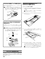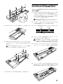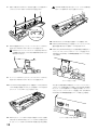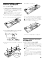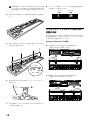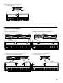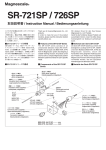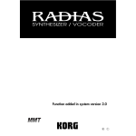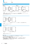
1
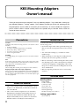
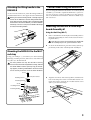
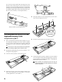
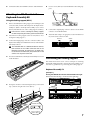
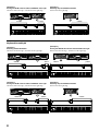
KKS Mounting Adapters Owner’s manual Thank you for purchasing the Korg MA-T rack tray (Mounting Adapter - Tray) and/or MA-L locking support (Mounting Adapter - Locking support). These product will allow you to take full advantage of the Korg Komponent System (KKS) to customize your instrument(s). To ensure trouble-free enjoyment, please read this owner’s manual carefully and use the product only as directed. Please retain this manual for future reference. ○ ○ ○ ○ ○ ○ ○ ○ ○ ○ ○ ○ ○ ○ ○ ○ ○ ○ ○ ○ ○ ○ ○ ○ ○ ○ ○ ○ ○ ○ ○ ○ ○ ○ ○ ○ ○ ○ ○ ○ ○ ○ ○ ○ ○ ○ ○ ○ ○ ○ ○ ○ ○ ○ ○ ○ ○ ○ ○ ○ ○ ○ ○ Precautions Cautions for use Location Using the unit in the following locations can result in a malfunction. • In direct sunlight • Locations of extreme temperature or humidity • Excessively dusty or dirty locations • Locations of excessive vibration • Close to magnetic fields To ensure that all steps are performed safely, please observe the following points. Handling To avoid breakage, do not apply excessive force to the switches or controls. Care If the exterior becomes dirty, wipe it with a clean, dry cloth. Do not use liquid cleaners such as benzene or thinner, or cleaning compounds or flammable polishes. Keep this manual After reading this manual, please keep it for later reference. Keeping foreign matter out of your equipment Never set any container with liquid in it near this equipment. If liquid gets into the equipment, it could cause a breakdown, fire, or electrical shock. Be careful not to let metal objects get into the equipment. • Perform all steps in the order specified, taking care that you use the correct parts in the correct orientation. • You will need a Phillips (+) screwdriver with a number 2 tip. • When attaching or removing the sound generator module, take care not to pinch your hand. • Before connecting or disconnecting the cables, make sure that the power of the sound generator module is turned off. Plugging or unplugging cables with the power on may cause the sound generator module to malfunction. • Before using this product, be sure to read “Safety cautions.” Included items Rack Tray (MA-T) About this manual • This owner’s manual refers to the RADIAS sound module as the RADIAS-R; and the M3 sound module as the M3-M. • This owner’s manual explains how to attach the RADIAS-R to the Keyboard Assembly 61, how to attach both the RADIAS-R and the M3-M to the Keyboard Assembly 73/88, and how to attach two M3-M modules to the Keyboard Assembly 88. 2 Lifting handle Double-sided tape Connection cable Screws (M5 x 12) Insulating washers Insulating bushings Module fastening screw (M3 x 8) 1 1 1 4 4 4 1 Locking support (MA-L) Screws (M4 x 6) 2 Attaching the lifting handle to the RADIAS-R As shown in the illustration, attach the lifting handle included with the MA-T to the upper left of the RADIAS-R. Before you attach the lifting handle, carefully wipe the surface of the RADIAS-R and the lifting handle with a clean cloth to remove any dirt or dust. If the lifting handle should come off after installation, peel off the doublesided tape, and use a new piece of double-sided tape to reattach the lifting handle. Caution when using the RADIAS-R If you are using the RADIAS-R attached to one of the keyboard assemblies, you’ll need to update the RADIAS to system version 2.0 or later. For cautions regarding use in this situation, refer to the RADIAS documentation “Functions added in system version 2.0.” Attaching the RADIAS-R to the Keyboard Assembly 61 Using the Rack Tray (MA-T) 1 Remove the M3-M from the Keyboard Assembly. (Refer to the Keyboard Assembly 61 owner’s manual section “Removing the module.”) Don’t lose the screws you removed or the sound module retaining bar part “A”; you’ll need these later. 2 As shown in the illustration, place the rack tray (MA-T) approximately in the center of the Keyboard Assembly 61. 3 Align the screw holes of the rack tray (MA-T) with the screw holes in the tab portion of the sound module retainers “B.” Fasten the rack tray using the two module retainer screws (M3 x 8) you removed in step 1. Mounting the RADIAS-R to the MA-T rack tray Using your Phillips (+) screwdriver, use the insulating bushings, insulating washers, and screws to attach the rack tray (MA-T) to the RADIAS-R. You must perform this step after the MA-T rack tray has been attached to the Keyboard Assembly, and with the sound module retainers part B (61 key) or the locking support (73/88 key) folded down. You must also be sure to securely fasten the screws at all four locations. Screw Insulating washer Insulating bushing Screw Front panel surface Insulating washer Insulating bushing 3 4 Noting the orientation of the sound module retaining bar that you removed in step 1, align the screw holes of the Keyboard Assembly with the screw holes of the retaining bar. Handtighten the four screws (M3 x 8), and then use your Phillips (+) screwdriver to tighten them firmly. Do not forcibly tighten the screws when they are not correctly aligned in the screw holes. Doing so will damage the screws. 7 Connect the connection cable to the TO KYBD connector of the RADIAS-R. Attaching both the M3-M and the RADIAS-R to the Keyboard Assembly 73/88 Using the rack tray (MA-T) and the locking support (MA-L) 1 Toward the module Don’t lose the screws you removed, the retaining bar, or the locking support; you’ll need these later. Toward the keyboard Cross-section of retainer part ‘A’ 5 Remove the M3-M and the retaining bar from the Keyboard Assembly 73/88. (Refer to the Keyboard Assembly 73/88 owner’s manual, “Module removal.”) Remove the locking support from the rear rail. (Refer to the Keyboard Assembly 73/88 owner’s manual, “Locking support assembly.”) 2 Remove the two cover panels. (Refer to the Keyboard Assembly 73/88 owner’s manual, “Cover panels.”) 3 Remove the cable clamp that is attached to the inside of the rear rail. As shown in the illustration, pull the connection cable out over the rack tray. Remove Attach Rear rail 4 6 4 The included cable is a dedicated cable for connection between the TO KYBD connector and the TO MODULE connector, or between the TO KYBD connector and the TO MODULE (2nd) connector. Do not connect it to any other connector. Use the four included screws, insulating washers and insulating bushings to attach the rack tray (MA-T) to the RADIASR. (Refer to “Mounting the RADIAS-R to the MA-T rack tray.”) When mounting the RADIAS-R to the rack tray, be careful not to pinch the cable between the rack tray and the RADIAS-R. Connect the straight plug of the connection cable included with the rack tray (MA-T) to the TO MODULE (2nd) connector. 5 Attach the two locking support to the rear rail. (Refer to “Positioning the locking support.”) 6 Place the rack tray (MA-T) and the M3-M on the Keyboard Assembly 73/88, and then route the cable connected to the TO MODULE (2nd) connector over the rack tray as shown in the illustration. 11 Fold down the M3-M and rack tray (MA-T), and then use the four included screws, insulating washers and insulating bushings to attach the rack tray (MA-T) to the RADIAS-R. (Refer to “Mounting the RADIAS-R to the MA-T rack tray.”) 7 Noting the orientation of the retaining bar that you removed in step 1, use your Phillips (+) screwdriver to tighten the four screws. When mounting the RADIAS-R to the rack tray, be careful not to pinch the cable between the rack tray and the RADIAS-R. Toward the module Toward the keyboard Cross-section of retainer part “A” 12 Connect the connection cable to the TO KYBD connector of 8 the RADIAS-R. Align the screw holes on the bottom of the M3-M with the screw holes in the locking support, and use two screws (M4 x 6) to fasten them securely. The M3-M has screw holes in two locations for attaching the locking support; use the screw hole located on the left as seen from the rear. 9 13 Move the M3-M and RADIAS-R to the upright position, attach the cable clamp in an appropriate location, and route the connection cable through it. 14 If you want to use the M3-M or RADIAS-R in the upright position, fasten the lock plate of the locking support. (Refer to the Keyboard Assembly 73/88 owner’s manual, “Raising the module”). Align the screw holes of the rack tray (MA-T) and the locking support, and use two screws (M4 x 6) to tighten them firmly. 10 Connect the cable connected to the TO MODULE connector to the M3-M’s TO KYBD connector. Route the other cable over the rack tray (MA-T) as shown in the illustration. With the module raised 5 If you want to use the module in the lowered position, rotate the latch of the locking support to the horizontal position and fasten it. In the case of the RADIAS-R, use the module retaining screws included with the rack tray to fasten the rack tray and the locking support. (Refer to the Keyboard Assembly 73/88 owner’s manual, “Lowering the module.”) 5 Noting the orientation of the retaining bar that you removed in step 1, fasten it using the four screws. With the module lowered (storage position) Toward the module Toward the keyboard Attaching only one RADIAS-R to the Keyboard Assembly 73/88 Using the rack tray (MA-T) 1 Cross-section of retainer part “A” 6 Route the connection cable as shown in the illustration. 7 Fold down the rack tray (MA-T), and then use the four included screws, insulating washers and insulating bushings to attach the rack tray (MA-T) to the RADIAS-R. (Refer to “Mounting the RADIAS-R to the MA-T rack tray.”) Remove the M3-M from the Keyboard Assembly 73/88. (Refer to Keyboard Assembly 73/88 owner’s manual, “Module removal.”) Remove the locking support. (Refer to Keyboard Assembly 73/88 owner’s manual, “Locking support assembly.”) Don’t lose the screws you removed, the retaining bar, or the locking support; you’ll need these later. 2 Re-attach the locking support to the rear rail. (Refer to “Positioning the locking support.”) 3 Position the rack tray (MA-T) on the keyboard 73/88. When mounting the RADIAS-R to the rack tray, be careful not to pinch the cable between the rack tray and the RADIAS-R. 4 6 Align the screw holes of the rack tray (MA-T) with the screw holes of the locking support. Use your Phillips (+) screwdriver to firmly tighten the two screws (M4 x 6). 8 Connect the cable to the TO KYBD connector of the RADIAS-R. 6 Use two screws (M4 x 6) to fasten the M3-Ms to the locking supports. 7 Connect the L-shaped plugs of the two cables to the TO KYBD connector of each M3-M module. 8 Attach the cable clamp to an appropriate location inside the rear rail, and route the connection cable. Attaching two M3-M units to the Keyboard Assembly 88 Using the locking support (MA-L) 1 Remove the M3-M, the locking support, the retaining bar, the connection cable, and the cable clamp from the Keyboard Assembly 88. (Refer to the Keyboard Assembly 73/88 owner’s manual, “Module removal” and “Locking support assembly.”) Don’t lose the screws, retaining bar, locking support, or cable clamp that you remove; you’ll need them later. 2 Attach the two locking supports to the rear rail. (Refer to “Positioning the locking support.”) 3 Connect the straight plugs of the two connection cables to the Keyboard Assembly 88’s TO MODULE connector and TO MODULE (2nd) connector. Remove The included cable is a dedicated cable for connection between the TO KYBD connector and the TO MODULE connector, or between the TO KYBD connector and the TO MODULE (2nd) connector. Do not connect it to any other connector. 4 Place the two M3-M units on the Keyboard Assembly 88 as shown in the illustration. Attach Rear rail Positioning the locking support The illustrations below show various examples of attaching the M3-M and RADIAS-R to the Keyboard Assembly 73/88. Use these as guidelines for positioning the locking support. Keyboard Assembly 73 [Example 1] Placing the RADIAS-R at the left and the M3-M at the right 290 mm from the left edge / 70 mm from the right edge 5 Noting the orientation of the retaining bar that you removed in step 1, fasten it using the four screws (M3 x 8). 290mm 70mm Toward the module Toward the keyboard Cross-section of retainer part “A” 7 [Example 2] Placing the M3-M at the left and the RADIAS-R at the right 610 mm from the left edge / 210 mm from the right edge 610mm [Example 3] Attaching only one RADIAS-R module 530 mm from the right edge 530mm 210mm Keyboard Assembly 88 [Example 2] Placing the RADIAS-R at the left and the M3-M at the right 400 mm from the left edge / 190 mm from the right edge [Example 1] Attaching two M3-M modules 630 mm from the left edge / 90 mm from the right edge 630mm 90mm [Example 3] Placing the M3-M at the left and the RADIAS-R at the right 730 mm from the left edge / 320 mm from the right edge 730mm 8 320mm 400mm 190mm [Example 4] Attaching only one RADIAS-R module 650 mm from the right edge 650mm KKSマウンティング・アダプター 取扱説明書 このたびは、コルグ・ラック・トレイ (MA-T) 、 またはリフトアップ・アタッチメント (MA-L) をお買い上げいただきまして誠にあり がとうございます。 本製品を末永くご愛用いただくためにも、 この取扱説明書をよくお読みになって正しい方法でご使用ください。 また、取扱説明書は大切に保管してください。 ○ ○ ○ ○ ○ ○ ○ ○ ○ ○ ○ ○ ○ ○ ○ ○ ○ ○ ○ ○ ○ ○ ○ ○ ○ ○ ○ ○ ○ ○ ○ ○ ○ ○ ○ ○ ○ ○ ○ ○ ○ ○ ○ ○ ○ ○ ○ ○ ○ ○ ○ ○ ○ ○ ○ ○ ○ ○ ○ ○ ○ ○ ○ 取り付け作業の前に、 必ずこの内容をよ くお読みください。 安全上のご注意 ・本製品の隙間に指などを入れない。 お客様がけがをしたり、本製品が破損する恐れがあります。 ・本製品に前後方向から無理な力を加えない。 本製品が転倒してお客様がけがをしたり、本製品が破損する恐れがあ ります。 ・外装のお手入れに、ベンジンやシンナー系の液体、コンパウンド質、 強燃性のポリッシャーは使用しない。 ご使用になる前に必ずお読みください ここに記載した注意事項は、製品を安全に正しくご使用いただき、あなたや 他の方々への危害や損害を未然に防ぐためのものです。 注意事項は誤った取り扱いで生じる危害や損害の大きさ、または切迫の程 度によって、内容を「警告」、 「注意」の2つに分けています。これらは、あな たや他の方々の安全や機器の保全に関わる重要な内容ですので、よく理解 した上で必ずお守りください。 火災・感電・人身障害の危険を防止するには 取扱説明書について ・ この取扱説明書は、RADIAS の音源ユニット部分を RADIAS-R、 M3 の音源ユニット部分を M3-M と記述しています。 ・ この取扱説明書は Keyboard Assembly 61 に RADIAS-R を取 り付ける方法、Keyboard Assembly 73/88 に RADIAS-R と M3-M の 2 台を同時に取り付ける方法、また Keyboard Assembly 88 に 2 台の M3-M を取り付ける方法を記述しています。 図記号の例 記号は、注意(危険、警告を含む) を示しています。 記号の中には、具体的な注意内容が描かれています。左の図は「一般的 な注意、警告、危険」を表しています。 記号は、禁止(してはいけないこと) を示しています。 記号の中には、具体的な注意内容が描かれることがあります。左の図は 「分解禁止」を表しています。 記号は、強制(必ず行うこと) を示しています。 記号の中には、具体的な注意内容が描かれることがあります。左の図は 「電源プラグをコンセントから抜くこと」を表しています。 以下の指示を守ってください 警告 この注意事項を無視した取り扱いをすると、 死亡や重傷を負う可能性が予想されます ・本製品を分解したり改造したりしない。 ・取扱説明書に書かれている「取り付け方」に従って、確実に設置する。 本製品が転倒または破損して、お客様がけがをする恐れがあります。 注意 この注意事項を無視した取り扱いをすると、傷害を負う可能性 または物理的損害が発生する可能性があります ・ネジなどに必要以上の力を加えない。 本製品が破損する恐れがあります。 ・不安定な場所に置かない。 本製品が転倒してお客様がけがをしたり、本製品が破損する恐れがあ ります。 ・本製品の上に乗ったり、重いものをのせたりしない。 本製品が転倒してお客様がけがをしたり、本製品が破損する恐れがあ ります。 作業時の注意 正しく安全に作業を行うためには、以下の項目に注意してください。 ・ 部品の種類や向きを間違わないように注意し、手順どおりに組み 立ててください。 ・ 先端サイズが No.2 のプラス・ドライバーをご用意ください。 ・ 音源モジュール取り付け、または取り外しをする場合などに、手を はさまないよう注意してください。 ・ 接続ケーブルを抜き差しする場合は、必ず音源モジュールの電源 を切った状態で行ってください。電源を入れた状態で抜き差しを 行うと、音源モジュールが正常に動作しなくなることがあります。 ・ 作業する場合は、必ず前述の「安全上の注意」をお読みになってか ら作業を行ってください。 付属品について ■ラック・トレイ (MA-T) フック 両面テープ 接続ケーブル ネジ(M5 × 12) 絶縁ワッシャ 絶縁ブッシュ モジュール固定ネジ(M3 × 8) 1個 1枚 1本 4個 4個 4個 1個 ■リフトアップ・アタッチメント (MA-L) ネジ(M4 × 6) 2個 9 RADIAS-R本体にフックを取り付ける 図のように RADIAS-R 本体の左上にラック・トレイ(MA-T)に付 属のフックを取り付けます。 Keyboard Assembly 61に RADIAS-Rを取り付ける ラック・トレイ (MA-T) を使用 フックを貼り付ける前にRADIAS-R本体の接着面をきれいな 布等でよく拭いて、 汚れ等を落としてください。 また、 貼り付け たフックがとれてしまった場合は、 両面テープをはがし、 付属 の両面テープでフックを貼り付け直してください。 1 K e y b o a r d A s s e m b l y 6 1 から M 3 - M を取り外します。 (Keyboard Assembly 61 取扱説明書「モジュールの取り外し 方」を参照) 取り外したネジ、 音源モジュール固定パーツAは、 後で使用す るので無くさないようにしてください。 2 図のように、ラック・トレイ (MA-T) をKeyboard Assembly 61 のほぼ中央に置きます。 ラック・トレイ (MA-T) にRADIAS-R を取り付ける お手持ちの+(プラス)ドライバーを使って、絶縁ブッシュ、絶縁 ワッシャ、 ネジでラック・トレイ(MA-T)にRADIAS-Rを取り付け ます。 この作業は、 ラック・トレイ(MA-T)がKeyboard Assembly に取り付けてある必要があります。 取り付け時は、必ず音源モ ジュール固定パーツB(61key) 、 またはリフトアップ・アタッ チメント (73/88key) を倒した状態で行ってください。 また、 必ず 4 箇所をネジでとめ、確実に締めてください。 3 ラック・トレイ(MA-T)のネジ穴と、音源モジュール固定パーツB のネジ穴を合わせます。手順 1 で取り外した 2 本のモジュール固 定ネジ(M3 × 8)で固定します。 ネジ 絶縁ワッシャ フロント・パネル側 絶縁ブッシュ ネジ 絶縁ワッシャ 絶縁ブッシュ 4 手順1で取り外した音源モジュール固定パーツ Aを向きに注意し て、Keyboard Assembly 側のネジ穴と KB カバーのネジ穴を合 わせます。4 本のネジ(M3 × 8)を軽く手で締め付けてから、お手 持ちの+ (プラス) ドライバーでネジを確実に締めて取り付けます。 ネジ穴がうまく合っていない状態で、ネジを無理に締め付け ないでください。ネジが破損する恐れがあります。 RADIAS-R使用時の注意 各Keyboard AssemblyにRADIAS-Rを取り付けてご使用になる場 合、RADIASのシステムをバーション2.0以降にする必要があります。 使用上の注意点などは、RADIAS の「システム・バージョン 2.0 の追加 機能」を参照してください。 10 Keyboard Assembly 73/88にM3MとRADIAS-Rの2台を取り付ける ラック・トレイ (MA-T) とリフトアップ・アタッチメント (MA-L) を使用 1 Keyboard Assembly 73/88 から M3-M と KB カバーを取り 外します。 (Keyboard Assembly 73/88取扱説明書「モジュー ルの取り外し方」を参照)リフトアップ・アタッチメントを取り外 します。 (Keyboard Assembly 73/88取扱説明書「リフトアッ プ・アタッチメントの取扱い」を参照) モジュール側 鍵盤側 取り外したネジ、KB カバー、リフトアップ・アタッチメント 固定パーツA 断面図 は、後で使用するので無くさないようにしてください。 2 2 つのカバー・パネルを取り外します。 ( Keyboard Assembly 73/88 取扱説明書「カバー・パネルの取扱い」を参照) 5 図のように、ラック・トレイの上に接続ケーブルを引き出します。 3 リア・レールの内側に取り付けてあるケーブル・クランプを取り外します。 取り外す 取り付ける リア・レール 4 ラック・トレイ(MA-T)に付属の接続ケーブルのストレート・プラ グ側を TO MODULE(2nd)に接続します。 付属の接続ケーブルは、TO KYBD 端子と TO MODULE 端 6 子、またはTO KYBD端子とTO MODULE(2nd)端子を接続 する専用ケーブルです。他の端子には接続しないでください。 付属の4本のネジでRADIAS-Rをラック・トレイ(MA-T)に取り 付けます。 (「ラック・トレイ(MA-T)にRADIAS-Rを取り付ける」 を参照) 5 2つのリフトアップ・アタッチメントをリア・レールに取り付けま す。 ( 「リフトアップ・アタッチメント取り付け位置の目安」 を参照) RADIAS-Rを取り付けるときに、ラック・トレイとの間に接 続ケーブルを挟まないように注意してください。 6 ラック・トレイ(MA-T)と M3-M を Keyboard Assembly 73/ 88に載せてから、TO MODULE(2nd)端子に接続されている接 続ケーブルを図のようにラック・トレイの上に引き出します。 7 RADIAS-R の TO KYBD 端子に接続ケーブルを接続します。 11 7 RADIAS-Rを取り付けるときに、ラック・トレイとの間に接 手順 1 で取り外した KB カバーを向きに注意して、お手持ちの+ 続ケーブルを挟まないように注意してください。 (プラス)ドライバーを使って 4 本のネジで固定します。 モジュール側 鍵盤側 KBカバー断面図 8 12 RADIAS-R の TO KYBD 端子に接続ケーブルを接続します。 13 M3-MとRADIAS-Rを起こした状態にし、ケーブル・クランプを M3-Mの底部のネジ穴とリフトアップ・アタッチメントのネジ穴 適切な位置に取り付けて、接続ケーブルを引き回します。 を合わせて、2 本のネジ(M4 × 6)でしっかり固定します。 M3-M にリフトアップ・アタッチメントを取り付けるネジ穴 は2箇所にありますが、リアから見て左側の取り付けネジ穴に 取り付けてください。 9 14 M3-M、または RADIAS-R を起こした状態で使用する場合は、リ フトアップ・アタッチメントのロック・プレートを固定します。 (Keyboard Assembly 73/88 取扱説明書「モジュールの起こ し方」を参照) ラック・トレイ(MA-T)とリフトアップ・アタッチメントのネジ穴 を合わせて、2 本のネジ(M4 × 6)でしっかり固定します。 10 TO MODULE 端子に接続されている接続ケーブルを M3-M の TO KYBD端子に接続します。 もう一方の接続ケーブルは、 図のよ うにラック・トレイ(MA-T)の上に引き出します。 11 M3-Mとラック・トレイ (MA-T)を倒した状態にしてから、付属の 4本のネジで、 RADIAS-Rをラック・トレイ (MA-T)に取り付けま す。 ( 「ラック・トレイ (MA-T) にRADIAS-Rを取り付ける」 を参照) 12 モジュールを起こした状態 また、倒した状態で使用する場合は、リフトアップ・アタッチメン トのストッパーを縦に回転させて固定します。RADIAS-Rの場合 は、 ラック・トレイに付属のモジュール固定ネジを使い、 ラック・ト レイとリフトアップ・アタッチメントを固定します。 ( Keyboard Assembly 73/88 取扱説明書「モジュールの倒し方」を参照) モジュールを倒した状態(収納状態) Keyboard Assembly 73/88に RADIAS-R1台だけ取り付ける 6 図のように接続ケーブルを引き出します。 7 ラック・トレイ(MA-T)を倒した状態にしてから、付属の4本のネ ラック・トレイ (MA-T) を使用 1 Keyboard Assembly 73/88 から M3-M を取り外します。 (Keyboard Assembly 73/88 取扱説明書「モジュールの取り 外し方」を参照)リフトアップ・アタッチメントを取り外します。 (Keyboard Assembly 73/88 取扱説明書「リフトアップ・ア タッチメントの取扱い」を参照) 取り外したネジ、KB カバー、リフトアップ・アタッチメント は、後で使用するので無くさないようにしてください。 2 リフトアップ・アタッチメントをリア・レールに取り付け直しま す。 ( 「リフトアップ・アタッチメント取り付け位置の目安」 を参照) 3 ラック・トレイ(MA-T)をKeyboard Assembly 73/88に置きます。 ジで、R A D I A S - R をラック・トレイ(M A - T )に取り付けます。 (「ラック・トレイ(MA-T)に RADIAS-R を取り付ける」を参照) RADIAS-Rを取り付けるときに、ラック・トレイとの間に接 続ケーブルを挟まないように注意してください。 4 ラック・トレイ (MA-T) のネジ穴と、 リフトアップ・アタッチメント のネジ穴を合わせます。お手持ちの+(プラス)ドライバーを使っ て、2 本のネジ(M4 × 6)でしっかり固定します。 8 RADIAS-R の TO KYBD 端子に接続ケーブルを接続します。 Keyboard Assembly 88に2台の M3-Mを取り付ける 5 手順1で取り外したKBカバーを向きに注意して、4本のネジで固 リフトアップ・アタッチメント (MA-L) を使用 定します。 1 Keyboard Assembly 88に取り付けてあるM3-M、 リフトアッ プ・アタッチメント、 KBカバー、 接続ケーブル、 ケーブル・クランプ を取り外します。 (Keyboard Assembly 73/88取扱説明書「モ ジュールの取り外し方」、 「リフトアップ・アタッチメントの取扱 い」を参照) 取り外したネジ、 KBカバー、 リフトアップ・アタッチメント、 ケーブル・クランプは、後で使用するので無くさないように してください。 2 モジュール側 2つのリフトアップ・アタッチメントをリア・レールに取り付けま す。 ( 「リフトアップ・アタッチメント取り付け位置の目安」 を参照) 鍵盤側 KBカバー断面図 3 Keyboard Assembly 88 の TO MODULE 端子と TO MODULE (2nd) 端子に、 2本の接続ケーブルのストレート・プラグ側を 接続します。 13 付属の接続ケーブルは TO KYBD 端子と TO MODULE 端 子、または TO KYBD 端子と TO MODULE(2nd)端子を接 続する専用ケーブルです。 他の端子には接続しないでくださ い。 4 8 リア・レールの内側にケーブル・クランプを適切な位置に取り付 け、接続ケーブルを引き出します。 取り外す 取り付ける 図のように、Keyboard Assembly 88に2台のM3-Mを置きま す。 リア・レール リフトアップ・アタッチメント取り付け 位置の目安 下記は、Keyboard Assembly 73/88 に M3-M、RADIAS-R を取り 付ける場合の例をいくつかあげています。 リフトアップ・アタッチメン トを取り付ける位置の目安としてください。 Keyboard Assembly73の場合 5 手順 1 で取り外した K B カバーを向きに注意して、4 本のネジ 【例 1】左側に RADIAS-R、右側に M3-M を配置するとき 左端から 290mm/ 右端から 70mm (M3 × 8)で取り付けます。 290mm 70mm モジュール側 鍵盤側 KBカバー断面図 【例 2】左側に M3-M、右側に RADIAS-R を配置するとき 左端から 610mm/ 右端から 210mm 6 2 本のネジ(M4 × 6)で M3-M をリフトアップ・アタッチメント に固定します。 610mm 7 2 本の接続ケーブルの L プラグ側を、それぞれの M 3 - M の T O KYBD 端子に接続します。 14 210mm 【例 3】 RADIAS-R を 1 台だけを配置するとき 右端から 530mm 530mm Keyboard Assembly88の場合 【例 1】2 台の M3-M を配置するとき 左端から 630mm/ 右端から 90mm 630mm 【例 2】左側に RADIAS-R、右側に M3-M を配置するとき 左端から 400mm/ 右端から 190mm 90mm 【例 3】左側に M3-M、右側に RADIAS-R を配置するとき 左端から 730mm/ 右端から 320mm 730mm 400mm 190mm 【例 4】RADIAS-R を 1 台だけを配置するとき 右端から 650mm 320mm 650mm 15 4015-2 Yanokuchi, Inagi-city, Tokyo 206-0812 Japan 2007 KORG INC. Printed in Japan