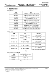
1
Product Specification
製品規格
108-5179
27APR11
Rev.E4
AMP-ECONOSEAL “J”-Ⅱ CONNECTOR
1.
Scope :
This specification covers requirements for product performance and test methods of
AMP-ECONOSEAL “J”-Ⅱ connectors.
2.
Product
Product Part Numbers and Descriptions :
The products of the following part numbers shall be governed under this specification.
Part Numbers
Descriptions
171630, 171662
.070 Series, Receptacle Contact
171631, 171661
.070 Series, Tab Contact
172746, 172888
178210, 176886
900324, 900325
Rubber Plug for .070 Series Contact
172748
Cavity Plug for .070 Series Connector
171632
.250 Series, Receptacle Contact
171633
.250 Series, Tab Contact
172747
Rubber Plug for .250 Series Contact
172749
Cavity Plug for .250 Series Connector
172743
.070 / .250 Combination, 15-Pos. Plug Housing Assembly
172744
.070 / .250 Combination, 15-Pos. Cap Housing
173090
.070 Series, 2-Pos. Plug Housing Assembly
173063
.070 Series, 2-Pos. Cap Housing
173091
.070 Series, 3-Pos. Plug Housing Assembly
173065
.070 Series, 3-Pos. Cap Housing
173914
.070 Series, 4-Pos. Plug Housing Assembly
173915
.070 Series, 4-Pos. Cap Housing
173919
.070 Series, 6-Pos. Plug Housing Assembly
173920
.070 Series, 6-Pos. Cap Housing
173891
.070 Series, 13-Pos. Plug Housing Assembly
173892
.070 Series, 13-Pos. Cap Housing
タイコ エレクトロニクス ジャパン合同会社 (〒213-8535 川崎市高津区久本 3-5-8)
Tyco Electronics Japan G.K. (3-5-8 Hisamoto Takatsu-ku Kawasaki, 213-8535)
© Copyright 2011 TE Connectivity All international rights reserved.
* : 商標 Trademark
1 of 29
Product Specification
3.
Definitions of Terms
Terms :
3.1
Contact:
108-5179
Contact is a metallic component member of connector to make electrical contact, capsulated in housing.
3.2
Housing:
Housing is an electrically insulating, plastic component member of connector to capsulate contacts in its
cavities. Cap housing that capsulate tab contacts, and plug housing that capsulate receptacle contacts, are
available.
3.3
Rubber Plug:
Rubber plug is an at achment rubber plug, used on the wire next to wire crimp of tab contact and receptacle
contact to provide water-tight sealing of connector assembly.
3.4
Cavity Plug:
Cavity plug is a cavity filler to protect cavity when it is not in use.
3.5
Seal Ring:
Seal ring is a component part attached on plug housing to provide water-tight connection between cap
housing, when the housings are mated.
3.6
Connector Assembly:
Connector assembly is an assembly, consisting of housing, with wire-crimped contacts filled in all or partial
cavity positions and furnished with all component parts required to provide water-tight connector functions.
Cap connector assembly containing tab contacts, and plug connector containing receptacle contacts and being
equipped with seal ring, are available.
4.
Material and Finish :
4.1
Contact:
Contact shall be made of brass or pre-tinned brass or plain bras with selective gold plating over nickel
underplate, conforming to Copper Alloy No. 260 of ASTM B 36, or pre-tinned phosphor bronze or plain
phosphor bronze with selective gold plating over nickel underplate.
4.2
Housing:
Housing shall be made of molded, heat-resistive 6/6 Nylon resin or polybuthylene terephthalate resin (PBT).
Rev. E4
2 of 29
Product Specification
4.3
108-5179
Rubber Plug:
Rubber plug shall be made of nitrile butadiene rubber (NBR).
4.4
Cavity Plug:
Cavity plug shall be made of nitrile butadiene rubber (NBR).
4.5
Seal Ring:
Seal ring shall be made of nitrile butadiene rubber (NBR).
5.
Product Design Feature,
Feature, Construction and Dimensions :
5.1
Contact:
Contact design feature, construction and dimensions shall be conforming to the applicable customer product
drawings. All tab contacts and receptacle contacts shall be mated regardless of the wire sizes applied.
5.2
Housing:
Product design feature, construction and dimensions shall be conforming to the applicable customer product
drawings. Housings shall be provided with polarization and locking mechanism with contact insertion entry
guide.
5.3
Rubber Plug:
Product design feature, construction and dimensions shall be conforming to the applicable product drawings.
5.4
Cavity Plug:
Product design feature, construction and dimensions shall be conforming to the applicable product drawings.
Rev. E4
3 of 29
Product Specification
6.
Performance Rating :
6.1
Temperature Rating:
108-5179
Temperature rating of the connector assemblies shall be within the range of –30℃ and 105℃, including the
temperature rising resulted from the energized operation effect in addition to the ambient temperature.
6.2
Applicable Wire Size:
The wires of the following sizes, shall be used for terminating the subject product connectors.
Contact
Part Number
Rubber Plug
Applicable Wire Size (mm2)
Insulation Diameter (mm)
171630
171631
172746
178210
900324
AV or AVS Wire
0.2, 0.3 or 0.5 mm2
One-wire Crimp
1.4 – 2.4
171661
171662
172888
176886
900325
AV or AVS Wire
0.5, 0.85 or 1.25m mm2
One-wire Crimp
2.0 – 2.6
172747
AV or AVS Wire
1.25, 2.0 or 3.0 mm2
One-wire Crimp
2.5 – 4.1
171632
171633
Notes : AV Wire = Low voltage wires and cables for automobiles per JIS C 3406 (Vinyl-insulated)
AVS Wire = Low voltage wires and cables for automobiles with thin
wall insulation which have been predominantly used for automobile
harness wiring according to the weight reduction trends of recent
automobile industry. Specification has been not established as
the end of 1983, quality being equivalent to AV wires.
Rev. E4
4 of 29
Product Specification
7.
108-5179
Performance
Performance Requirements and Test Methods :
When the products are tested in accordance with the test methods specified in Paragraph of 7.2, in
accordance with the test sequence specified in Paragraph 7.3, the requirements specified in Table 3
shall be met.
7.1
Summary of Requirements:
Test Items
(Paragraph Number
of Test Methods)
Appearance
(Para. 7.2.1)
Initial
Final
Connector shall appear normal without evidence of defects such as cracks, damages and
breakage, loose and loss of component parts, rust and fusion that are detrimental to
connector functions.
Insertion Force of
Contact or Connector
(Para. 7.2.2)
.070 : 2.94 – 7.85N
.250 : 6.86 – 14.7N
Extraction Force of
Contact or Connector
(Para. 7.2.3)
.070 : 2.94 – 7.85N
.250 : 5.88 – 13.7N
Termination
Resistance
(Low Level)
(Para. 7.2.4)
Performance Requirements of Connector
Performance Requirements
of Contact
(Initial)
Pos.
2
3
4
6
13
15
N
Max.
49
58.8
68.6
78.5
127
137
Pos.
2
3
4
6
13
15
N
Max
39.2
49
68.6
78.5
127
137
3.0 mΩ max.
10.0 mΩ max.
Table 3 (To be continued)
Rev. E4
5 of 29
Product Specification
7.1
108-5179
(Continued):
Test Items
(Paragraph Number
of Test Methods)
Performance Requirements
of Contact
(Initial)
Termination Resistance
(Para. 7.2.5)
Insulation
Resistance
(Para. 7.2.6)
Dielectric Strength
(Para. 7.2.7)
Handling Touch of
Connector Insertion /
Extraction
(Para. 7.2.8)
Contact Retention
Force (Para. 7.2.10)
Housing Retention
Force (Para 7.2.11)
Water-tight Sealing
(Para. 7.2.12)
Heat Resistivity
(Para. 7.2.13)
Cold Resistivity
(Para. 7.2.14)
“Kojiri” Resistivity
(Para. 7.2.15)
Cleaning Solvent
Resistivity
(Para. 7.2.16)
Oil Resistivity
(Para. 7.2.17)
Ozone Resistivity
(Para. 7.2.18)
Weather Aging
(Para. 7.2.19)
Dust Bombardment
(Para. 7.2.20)
(Initial)
(Final)
3mV/A max.
10mV/A max.
100MΩ min.
Connector shall appear normal without showing
evidence of abnormalities.
No obstruction shall be felt tactually during insertion / extraction of contacts and
connectors.
Wire Size
Crimp Tensile Strength
(Para. 7.2.9)
Performance Requirements of Connector
Tensile
Strength
mm2
(AWG)
N Min.
0.2
0.3
0.5
0.85
1.25
2.0
3.0
(#24)
(#22)
(#20)
(#18)
(#16)
(#14)
(#12)
68.6
78.5
88.3
127.0
177.0
265.0
294.0
78.5N min.
98.1N min.
49KPa(49mN/mm2) Min.
29.4KPa(29.4mN/mm2)
Min.
Performance
requirements for each
test item shall be met
when tested
environmentally and
durability in the sequence
specified in Table 5.
Table 3 (To e continued)
Rev. E4
6 of 29
Product Specification
7.1
108-5179
(Continued Ⅱ)
Test Items
(Paragraph Number
of Test Methods)
Performance Requirements
of Contact
(Initial)
Performance Requirements of Connector
(Initial)
(Final)
Performance
requirements for each
test item shall be met
when tested
environmentally and
durably in the sequence
specified in Table 5.
Temperature Rising
(Para. 7.2.21)
Water Splash
(Para. 7.2.22)
Current
(Para. 7.2.23)
Table 3 (End)
7.2
7.2.1
Test Methods:
Appearance:
Visually and tactually inspect the product samples for evidence of abnormalities such as cracks, damages,
breakage, loose and loss of component parts, rust, fusion and deformation that are detrimental to connector
functions.
7.2.2
Insertion Force of Contact or Connector:
Securely fasten one of the mating pair of contacts or connector assemblies on the head of
tensile testing
machine, and apply an axial push-in load to the counterpart contact or connector to mate them together, by
operating the head to travel with the speed at a rate of 100mm approximately a minute. The force required to
mate the samples without locking mechanism set in effect, shall be measured and recorded.
7.2.3
Extraction Force of Contact or Connector:
Securely fasten one of the mated pair of contacts or connector assemblies on the head of tensile testing
machine, and apply and axial pull-off load to the free end of the mated samples to separate them by operating
the head to travel with the speed at a rate of 100mm approximately a minute. The force required to extract
without locking leg set in effect, shall be measured and recorded.
7.2.4
Termination Resistance (Low Level):
Mated pair of contacts or connectors shall be tested by applying closed circuit test current of 50mA max. at
open circuit voltage of 50mV max. in the test circuit as shown in Fig.1. Measure the millivolt drop of the circuit
by probing across the points 75mm apart from the wire crimps each side (Y – Y´in Fig.1). Low level
termination resistance shall be obtained by calculation after deducting the resistance of the totally 150mm
long wires used for the termination. Measurement shall be done one position after one, respectively.
Rev. E4
7 of 29
Product Specification
108-5179
Fig. 1
7.2.5
Termination Resistance:
Mated pair of contacts or connectors shall be tested by applying closed circuit test current of 1A at open
circuit voltage of 12V DC in the test circuit as shown in Fig. 1. Measure the millivolt drop of the test circuit
after the temperature of the circuit becomes stabilized, by probing across the points 75mm apart from the
wire crimps each side (Y – Y´in Fig.1). Termination resistance shall be obtained by calculation after deducting
the resistance of totally 150mm long wires used for the termination. Measurement shall be done one position
after one respectively. To facilitate uniform current flow on the wires, solder must be applied to the probing
points with sufficiently long removal of wire insulation.
7.2.6
Insulation Resistance:
Mated pair of connectors shall be tested for insulation resistance, with all the contacts series wired as shown
in Fig.2. Test potential of 500V DC shall be applied between the adjacent contacts and between the contacts
and the ground. Measure the insulation resistance by using insulation megohmmeter.
Fig. 2
Rev. E4
8 of 29
Product Specification
7.2.7
108-5179
Dielectric Strength:
Mated pair of connectors shall be tested by applying test potential of 1000V AC with commercial frequency
between the adjacent contacts that are series wired as shown in Fig.2. The test potential shall be kept for 1
minute.
7.2.8
Handling Touch of Connector Insertion / Extraction:
Check handling touch of connector if obstruction is felt during insertion / extraction assembly operation, by
manually inserting and extracting repeatedly.
7.2.9
Crimp Tensile Strength:
A 100mm long wire crimped contact shall be securely fastened on the head of tensile testing machine, and
apply an axial pull-off load to the wire by operating the head to travel with the speed at a rate of 100mm
approximately a minute. Crimp tensile strength is determined when the wire is broken or is pulled out of the
wire crimp. Measure and record the force required to separate the wire from the wire crimp.
7.2.10
Contact Retention Force:
Load the contact in housing cavity that is crimped on a 100mm long, 0.85mm2 (#18 AWG) or greater wire. Then,
securely fasten the contact-loaded connector on the tensile testing machine, and apply an axial pull-off load
to the end of crimped wire by operating the head to travel with the speed at a rate of 100mm approximately a
minute. The force required to dislodge the contact from the loaded contact position shall be measured and
recorded.
7.2.11
Housing Retention Force:
Mate the contact-loaded connectors with the locking mechanism set in effect, and fasten one of the
connectors on the tensile testing machine. Then, apply an axial pull-off load to separate them to the
counterpart connector uniformly by operating the head to travel with the speed at a rate of 100mm
approximately a minute. The force required to separate the connectors with or without disengagement or
breakage of locking mechanism.
7.2.12
Water-tight Sealing:
Suspend the assembled connector in the tap water in the tub immersingly, as shown in Fig.3. With the tub
chamber closed, blow compressed air into it until inside pressure reaches to 9.8Kpa (9.8mN/mm2) and keep the
pressure level for 1 minute. If the connector withstands the pressure without showing signs of water leakage
into housing, increase the pressure level by the steps of graduation of 9.8Kpa (9.8mN/mm2) each time.
The circuitry of the testing connector shall be monitored for current leakage by applying the test current of
12V during the pressure elevation.
Rev. E4
9 of 29
Product Specification
108-5179
Fig. 3
7.2.13
Heat Resistivity:
Expose mated pair for connectors under the elevated temperature of 120±2℃ in the test oven for 120 hours.
After completion of test duration, take out of the oven and recondition the sample in the room temperature.
7.2.14
Cold Resistivity:
Expose mated pair of connectors under the frozen temperature of – 50±5℃ for 120 hours in the test
chamber. After completion of the test duration, take out of the chamber, and recondition the sample in the
room temperature.
7.2.15
“Kojiri” Resistivity:
Apply one cycle each of reciprocating, twisting and bending torque force of 196N・cm (T) to free-end side of
mated connectors with the counterpart connector securely fastened on the testing fixture. The torque shall be
applied at every 1mm depth in unmating way until the connectors are separated. Making one separation a
cycle, repeat the motion for 25 cycles for front-rear direction of the connectors. After one-direction
movement cycles are completed, apply the forcing motion in the same manner to the right-left direction of the
mated pair of the connectors, for another 25 cycles.
Fig. 4
This method may be manually simulated by repeating insertion / extraction with Kojiri movement by hand.
Rev. E4
10 of 29
Product Specification
7.2.16
108-5179
Cleaning Solvent Resistivity:
Immerse assembled connector in commercially available solvent for cleaning automobile front-shield glass
which is controlled at 50±2℃ for 1 hour. After the test duration, the sample connector shall be rinsed in tap
water for 5 minutes, and dried in the room temperature without aid of powered ventilation.
7.2.17
Oil Resistivity:
Mated pair of connectors shall be tested by immersing into the following kinds of test oil, in the sequence
stated below.
1.
2.
3.
4.
7.2.18
Engine Lubricant oil conforming to SAE 10W
or equivalent.
Kerosene at room temperature for cleaning.
Gasoline conforming to JIS K 2202 or equivalent, at
room temperature.
Drying in the room temperature
50℃ for 1 hour
for 5 minutes
for 1 hour
as required
Ozone Resistivity:
Mated pair of connectors shall be exposed under the ozone atmosphere of 50±5pphm for 24 hours in
accordance with JIS K 6301 Para.16. After the test duration, the sample shall be taken out from the test
chamber, and reconditioned in the room temperature. The chamber shall be kept at 40±2℃. The tested
condition of cracking on rubber parts shall be recorded in accordance with Para. 16.6 of JIS K 6301.
7.2.19
Weather Aging (Accelerated Aging Test by using Weathermeter):
Mated pair of connectors shall be tested for 150 hours in accordance with sunshine carbon weathermeter in
accordance with the method specified in Para. 5.4 (WAS – IS) of JIS D 0205, in the temperature at 63±3℃.
The tested condition of cracking on rubber parts shall be recorded in accordance with Para. 16.6 of JIS K
6301.
7.2.20
Dust Bombardment:
Hang mated pair of connectors in the middle of closed test chamber whose three dimensions are 1,000mm
respectively (1m3 capacity), where the connector assemblies are subject to undergo dust bombardment testing
by ejecting 1.5kg of Portland Cement or dust particles of Kanto Loam Layers with the use of powered blower
fan to disperse within the chamber at a rate of 10 seconds once every 15 minutes totally for 1 hour. The
sample connector shall be placed at the place 150mm apart from the chamber wall. After the test duration,
connectors shall be inserted and extracted for 3 cycles.
Note: Kanto Lam Layers = Volcanic soil layers typically found in the eastern areas of Mt. Fuji, extending to
cover up to near Tokyo in Kanto District, Japan.
Rev. E4
11 of 29
Product Specification
7.2.21
108-5179
Temperature Rising:
All .070 and .250 contacts are series wired into two separate circuits in segregation by contact sizes
respectively, and apply test current of the intensity obtained from the calculation by using coefficient factors
specified in Table 4 until the temperature rising becomes stabilized. Measurement shall be done by probing the
temperature on the surface of contact wire crimp. The test shall be done in the draft-free test chamber.
Wire Size
0.2 mm2
0.3 mm2
0.5 mm2
0.85 mm2
1.25 mm2
2.0 mm2
3.0 mm2
Test Current
A (DC)
7.0
9.0
11.0
14.5
18.5
25.0
34.0
No. of Pos.
1
2–3
4–5
6–8
9 – 12
13 and over
Reduction
Coefficient
1
0.75
0.6
0.55
0.5
0.4
Table 4a & 4b
Note:Applicable intensity of the test current
can be obtained by calculation of the
specified test current for each wire size
multiplied by the reduction coefficient.
7.2.22
Water Splash:
Hang the test sample in the test chamber and expose under the elevated atmosphere of 120±3℃ fro 40
minutes, immediately after this, followed by undergoing water splash conditioning by sprinkling water having
temperature of normal atmosphere for 20 minutes. Making this a cycle, repeat 48 cycles of the test in
accordance with the test method specified in Para. S1 of D 0203.
During the test, the test current of 12V shall be applied between the contacts, and circuits shall be monitored
and current leakage shall be recorded. For this test, the length of the lead shall be 2 meters with the end of
which to be placed outside of the chamber.
7.2.23
Current-loaded Vibration:
All .070 and .250 contacts are series-wired into two separated circuits in segregation by contact sizes
respectively, and fasten the connectors loaded with the crimped contacts on the vibration testing machine as
shown in Fig.5. Testing shall be done by applying vibration having accelerated velocity of 44m/s2 (4.5G) ‘s in
sweeping vibration changing in the range of 20-200Hz at a rate of one reciprocation cycle every 3 minutes.
The vibratile conditioning shall be applied to “X” axis for 30 hours, to “Y” axis for 30 hours and to “Z” axis for
40 hours. At the end of vibration for one axis, termination resistance (low level) shall be measured. During
vibration, test current obtained from the calculation in the same manner specified in Para.7.2.21 shall be
applied with intervals for 100 cycles, each cycle consisting of 45 minutes “ON” and 15 minutes “OFF”.
Rev. E4
12 of 29
Product Specification
108-5179
Fig. 5
Rev. E4
13 of 29
Product Specification
108-5179
7.3 Test Sequence:
All the tests shall be performed in the sequence specified in Table 5.
Test Sequence
Classification
Contact
Sample Groups
Test Item
Appearance
(Confirmation of Products)
Contact or Connector
Insertion Force
Contact or Connector
Extraction Force
Termination Resistance
(Low Level)
Connector
Ⅰ
Ⅱ Ⅰ
1
1
1
Ⅱ
Ⅲ
1
1
2
2
Ⅴ
1
1
1
3
6
8
2
2
Water-tight Sealing
5
7
9
5
2
9
5
11
Insulation Resistance
3
Dielectric Strength
Ⅷ
1
4
1
4
2
5
2
5
7
8
3
6
6
10
4
Handling Touch of
Connector
Insertion and Extraction
3
Contact Retention Force
2
Housing Retention Force
12
Heat Resistivity
5
Cold Resistivity
7
Water Splash
2
“Kojiri” Resistivity
4
2
Current-Loaded Vibration
6
Cleaning Solvent Resistivity
4
Oil Resistivity
6
Ozone Resistivity
3
Weather Aging
3
Dust Bombardment
Temperature Rising
Ⅶ
11
Termination Resistance
Crimp Tensile Strength
Ⅵ
10
4
3
Ⅳ
8
3
Table 5
Note:
Rev. E4
The numbers in the columns indicate the sequence in which the tests are performed.
14 of 29
Product Specification
8
Quality Assurance Provisions :
8.1
Test Conditions:
108-5179
Unless otherwise specified, all the tests shall be performed in any combination of the following test conditions.
Temperature
Relative Humidity
Atmospheric Pressure
15 – 35℃
45 – 75%
86.7 – 107KPa (650 – 800mmHg)
Table 6
8.2
Qualification Testing:
8.2.1
Sample Preparation:
All the samples to be employed for the tests, shall be prepared in accordance with AMP Application
Specification, 114-5082, Crimping AMP-ECONOSEAL “J” MARK Ⅱ Connector Contacts, by using the wires
of the sizes specified in Table 7.
Unless otherwise specified, no sample shall be reused for the tests.
8.2.2
Number of the Samples:
Each group of the sample contacts shall consist of more than 10 sets of prepared contacts, and connector
sample group shall consist of more than 2 sets of assembled connectors.
8.2.3
Applicable Wires:
For termination of the sample contacts to be used for the tests, the wires of the following sizes shall be used.
Wire Size
Strand Composition
Calculated Cross-sectional
Area of Conductor
Remarks
Nominal
mm2
(AWG)
Diameter
of a Strand
No. of
Strands
mm2
CMA
0.2
(#24)
0.20
7
0.22
434
0.3
(#22)
0.26
7
0.37
733
0.5
(#20)
0.32
7
0.56
1,111
0.85
(#18)
0.32
11
0.88
1,746
1.25
(#16)
0.32
16
1.29
2,540
2.0
(#14)
0.32
26
2.09
4,127
3.0
(#12)
0.32
41
3.30
6,508
JIS C 3406
Wires and
Cables for
Auto mobiles
(AV Wires &
AVS Wires
with Thin
Insulation Wall
Table 7
Rev. E4
15 of 29
Product Specification
9
9.1
108-5179
Application and Handling :
Crimpling and Handling:
All the wire crimping and handling shall be done moderately in conformance with the procedures and
workmanship evaluation levels specified in AMP Application Specification 114-5082, Crimping of
AMP-ECONOSEAL “J” MARK Ⅱ, Combination, 15-position Connector Contacts.
Harness assembly operation and extraction / loading of contacts to and from the housing must be done
according to the instructions provided in the customer manual CM-229J.
10
Reference Documents :
JASO D 605
Multi-Position Connectors for Automobiles
JASO D 7101
Test Methods for Plastic Molded Component Parts
JIS C 3406
Low Voltage Cables for Automobiles
JIS D 0203
Method of Moisture, Rain and Spray Test for Automobile Parts
JIS D 0204
Method of High and Low Temperature Test for Automobile Parts
JIS D 1601
Vibratile Testing Method for Automobile Parts
JIS D 0205
General Rules of Weatherability for Automobile Parts
JIS K 6301
Physical Testing Methods for Vulcanized Rubber
JIS K 2202
Motor Gasoline
114-5082
Application Specification, Crimping of AMP-ECONOSEAL “J”,
MARK Ⅱ, .070/.250 Combination, 15-Position Connector Contacts
Rev. E4
CM-229J
Customer manual
501-5364
Qualification Test Report
16 of 29
Product Specification
1.
108-5179
適用範囲 :
本規格はエコノシール “J”-Ⅱコネクタについて規定する。
2.
製品型番 :
第1表
型
Rev. E4
番
名
171630, 171662
.070 シリーズ・リセプタクル・コンタクト
171631, 171661
.070 シリーズ・タブ・コンタクト
172746, 172888
178210, 176886
900324, 900325
.070 用ラバープラグ
称
172748
.070 用キャビティープラグ
171632
.250 シリーズ・リセプタクル・コンタクト
171633
.250 シリーズ・タブ・コンタクト
172747
.250 用ラバープラグ
172749
.250 用キャビティープラグ
172743
.070/.250 コンビネーション 15 極プラグ・ハウジング・アッセンブリ
172744
.070/.250 コンビネーション 15 極キャップ・ハウジング
173090
.070 シリーズ 2 極プラグ・ハウジング・アッセンブリ
173063
.070 シリーズ 2 極キャップ・ハウジング
173091
070 シリーズ 3 極プラグ・ハウジング・アッセンブリ
173065
.070 シリーズ 3 極キャップ・ハウジング
173914
070 シリーズ 4 極プラグ・ハウジング・アッセンブリ
173915
.070 シリーズ 4 極キャップ・ハウジング
173919
070 シリーズ 6 極プラグ・ハウジング・アッセンブリ
173920
.070 シリーズ 6 極キャップ・ハウジング
173891
070 シリーズ 13 極プラグ・ハウジング・アッセンブリ
173892
.070 シリーズ 13 極キャップ・ハウジング
17 of 29
Product Specification
108-5179
3.
用語の
用語の意味 :
3.1
コンタクト ; コネクタの構成部品である接触子をいう。
3.2
ハウジング ; コネクタの構成部品であるコンタクトを収容するものをいう。
これにはタブコンタクトを収容するキャップハウジングとリセプタクルコンタクトを収容する
プラグハウジングがある。
3.3
ラバープラグ ; 防水性を得る目的でタブコンタクト及びリセプタクルコンタクトの電線側に装着
されるゴムをいう。
3.4
キャビティープラグ ; 2 極以上のコネクタの場合、コンタクトを使用しない極数のハウジング
ゴム栓穴に埋め込んで使用されるものをいう。
3.5
シールリング ; プラグハウジングに装着されており、キャップハウジングと嵌合した時両者との
間で防水性を得る目的で使用されるものをいう。
3.6
コネクタ
4.
使用材料・
使用材料・表面処理 :
4.1
コンタクト ; ASTM B 36 COPPER ALLOY 260 に準拠する黄銅条及び錫めっき付黄銅条及び
全面ニッケル下地めっき付部分金めっきが施された黄銅条又は錫めっき付りん青銅条及び
全面ニッケル下地めっき付部分金めっきが施されたりん青銅条より製造される。
4.2
ハウジング ; 耐熱 66 ナイロン樹脂又はポリプチレン・テレフタレート(PBT)樹脂より製造される。
4.3
ラバープラグ ; ニトリルゴム(NBR)より製造される。
4.4
キャビティープラグ ; ニトリルゴム(NBR)より製造される。
4.5
シールリング ; ニトリルゴム(NBR)より製造される。
5.
形状・
形状・構造及び
構造及び寸法 :
5.1
コンタクト ; 形状、構造及び寸法は該当する図面に合致していること。すべてのタブ・コンタクトとリセプタク
ルコンタクトは適用電線範囲に関係なく相互に嵌合できる。
5.2
ハウジング ; 形状、構造及び寸法は該当する図面に合致していること。誤嵌合防止機構、ハウジング相互
のロック機構及びコンタクト挿入ガイドを有する。
5.3
ラバープラグ ; 形状、構造及び寸法は該当する図面に合致していること。
5.4
キャビティープラグ ; 形状、構造及び寸法は該当する図面に合致していること。
Rev. E4
; ゴム栓を装着した電線を圧着し、ハウジングに全極アッセンブリしたものをいう。
これにはタブコンタクトをアッセンブリしたキャップハウジングとリセプタクルコンタクト
及びシールリングをアッセンブリしたプラグハウジングがある。
18 of 29
Product Specification
6.
使用条件 :
6.1
使用温度範囲
108-5179
-30~105℃(周囲温度+通電による温度上昇)
6.2
適用電線範囲
第2表
コンタクト
171630
171631
171661
171662
型番
ラバープラグ
172746
178210
900324
172888
176886
900325
171632
171633
172747
適用電線範囲(mm2)
AV 及び AVS
0.2、0.3、0.5
の一本圧着
AV 及び AVS
0.5、0.85、1.25
の一本圧着
AV 及び AVS
1.25、2、3
の一本圧着
絶縁被覆外径(mm)
1.4~2.4
2~2.6
2.5~4.1
※薄肉自動車電線(AVS)
7
性能及び
性能及び試験方法 :
第 7.2 項(試験方法)及び第 7.3 項(試験順序)に基づき試験した結果、第 3 表の性能を満足すること。
第3表
項目
外観
試験
方法
7.2.1
コンタクト又は
コネクタの挿入力
コンタクト又は
コネクタの引抜力
ローレベル抵抗
総合抵抗
絶縁抵抗
耐電圧
挿抜のフィーリング
7.2.4
7.2.5
7.2.6
7.2.7
7.2.8
圧着部引張強度
7.2.9
Rev. E4
7.2.2
7.2.3
コンタクトの性能
コネクタの性能
初期性能
初期性能
耐久・環境試験後の性能
亀裂、割損、破損、がた、部品のはずれ、錆び、溶解等で機能を損う欠点のない
こと。
.070 シリーズ;2.94-7.85N
極数
2
3
4
6
13
15
49
58.8 68.6 78.5 127 137
.250 シリーズ;6.86-14.7N
N 以下
.070 シリーズ;2.94-7.85N
極数
2
3
4
6
13
15
49
68.6 78.5 127 137
.250 シリーズ;5.88-13.7N
N 以下 39.2
3mΩ以下
10mΩ以下
3mV/A 以下
10mV/A 以下
100MΩ以上
異常なきこと
有害な引掛り等のないこと
0.2mm2-68.6N 以上
0.3mm2-78.5N 以上
0.5mm2-88.3N 以上
0.85mm2-127.0N 以上
1.25mm2-177.0N 以上
2.0mm2-265.0N 以上
3.0mm2-294.0N 以上
19 of 29
Product Specification
コンタクト保持力
ハウジング保持力
試験
方法
7.2.10
7.2.11
シール性
7.2.12
耐熱性
耐寒性
耐こじり性
耐洗剤性
耐油性
耐オゾン性
耐候性
耐塵性
温度上昇
散水
複合環境
7.2.13
7.2.14
7.2.15
7.2.16
7.2.17
7.2.18
7.2.19
7.2.20
7.2.21
7.2.22
7.2.23
項目
7.2
試験方法
7.2.1
外観
コンタクトの性能
初期性能
108-5179
コネクタの性能
耐久・環境試験後の性能
78.5N 以上
98.1N 以上
29.4Kpa 以上
49Kpa 以上
(29.4mN/mm2)
(49mN/mm2)
初期性能
第 5 表に示す順序で耐久・
環境試験を行ったとき性能を
満足すること。
外観を目視及び感触により観察し、有害な亀裂、割損、がた、部品のはずれ、錆、溶解及び変形等
の有無を確認する。
7.2.2
コンタクト又はコネクタの挿入力
コンタクト又はコネクタの一方を固定し、他方を軸方向に毎分約 100mm の一定速度で操作する。
なお、ハウジングのロック機構は作用させて行う。
7.2.3
コンタクト又はコネクタの引抜力
コンタクト又はコネクタの一方を固定し、他方を軸方向へ毎分約 100mm の一定速度で操作する。
なお、ハウジングのロックレグは押し下げて行う。
7.2.4
ローレベル抵抗
コンタクト又はコネクタを嵌合した状態で開放電圧 DC50mV 以下、短絡電流 50mA 以下を通電し、
圧着部より 75mm 離れた点で抵抗を測定する。(第 1 図の Y-Y´間)
ローレベル抵抗は、Y-Y´間の抵抗から 150mm の電線の抵抗分を差引いて算出する。
なお、測定は 1 極づつ行うものとする。
Rev. E4
20 of 29
Product Specification
108-5179
第1図
7.2.5
総合抵抗
コンタクト又はコネクタを嵌合した状態で開放電圧 DC12V、短絡電流 1A を通電しコンタクトの温度が
安定した後、圧着部より 75mm 離れた点で電圧降下を測定する。(第 1 図の Y-Y´間)
総合抵抗は、Y-Y´間の電圧降下から 150mm の電線の電圧降下を差引いて算出する。
なお、測定は 1 極ずつ行うものとする。Y-Y´点は被覆を余分にむきとって電流密度を一様にするため、
プローブをあてる電線部分に半田をもる。
7.2.6
絶縁抵抗
コネクタを嵌合した状態で第 2 図の如く、隣接するコンタクト相互間、及びコンタクト対ハウジング間
(対アース間)を測定する。
なお、測定電圧は DC500V とする。
7.2.7
耐電圧
コネクタを嵌合した状態で第 2 図の如く、隣接するコンタクト相互間及びコンタクト対ハウジング間
に商用周波数の AC1000V を 1 分間印加する。
Rev. E4
21 of 29
Product Specification
108-5179
第2図
7.2.8
挿抜のフィーリング
コンタクト又はコネクタの挿入、引抜きを手動にて行い、そのフィーリングを触感にて確認する。
7.2.9
圧着部引張強度
約 100mm の長さの電線を圧着したコンタクトを固定し、電線を軸方向に毎分約 100mm の一定速度で引張り、
電線の破断又は圧着部から電線の引抜けた時の荷重を測定する。
7.2.10
コンタクト保持力
ハウジングに約 100mm の長さ、0.85mm2 以上の断面積の電線を圧着下コンタクトが組込まれたコネクタを
固定し、電線を軸方向へ毎分約 100mm の一定速度で引張りコンタクトがハウジングから抜けた時の荷重を測
定する。
7.2.11
ハウジング保持力
コネクタを嵌合した状態で一方を固定し、他方を軸方向へ毎分約 100mm の一定速度で引張り、
ロック機構外れ又は破損して嵌合の外れた時の荷重を測定する。
Rev. E4
22 of 29
Product Specification
7.2.12
108-5179
シール性
第 3 図に示す試験装置内の水中にコネクタを吊るし、装置内に圧縮空気を送り、9.8Kpa(9.8mN/mm2)の
圧力を 30 秒間保つ。コネクタ内への浸水がなければ 9.8Kpa(9.8mN/mm2)ずつ上げていく。
試験中のコネクタ内への浸水の有無は、コネクタの各極間に 12V の電圧を印加しリーク電流を監視することに
より確認する。
第3図
7.2.13
耐熱性
コネクタを嵌合した状態で 120±2℃に保たれた恒温槽に 120 時間放置し、その後取り出して常温に戻るまで
放置する。
7.2.14
耐寒性
コネクタを嵌合した状態で-50±5℃に保たれた恒温槽に 120 時間放置し、その後取り出して常温に戻るまで
放置する。
7.2.15
耐こじり性
コネクタを引抜き時に第 4 図の如くコネクタの一方を固定し、他方を 1mm 間隔でコンタクト同士の嵌合が外れ
るまで引抜きながら、各段階で前後方向に 1 往復、196N・cm(T)のトルクを加える。これを 1 サイクルとして
25 サイクル行う。次に左右方向も同様に 1 往復 196N・cm(T)のトルクを加える。これを 1 サイクルとして 25
サイクル行う。又は手指により、こじりながら 50 回挿抜を繰り返す。
Rev. E4
23 of 29
Product Specification
108-5179
第4図
7.2.16
耐洗剤性
50±2℃のウォッシャ液(市販品)にコネクタを 1 時間浸漬し、その後水道水中に 5 分間浸漬したのち、
自然乾燥する。
7.2.17
耐油性
コネクタを嵌合した状態で 50±2℃のエンジン油(SAE10W)又は同等品、常温のガソリン(JIS-2202)又は
同等品、及び常温の白灯油を使用し、次の順序で試験を行う。
エンジン油
1 時間浸漬
→ 白灯油洗浄
5 分間浸漬
→ ガソリン
1 時間浸漬
→ 自然乾燥
7.2.18
耐オゾン
コネクタを嵌合した状態で 40±2℃に保たれた密閉容器内に吊るし、JIS K 6301 第 16 項に基づき、
オゾン濃度 50±5pphm 中に 24 時間放置後取り出し室温に放置する。
ゴムの亀裂状態は JIS K 6301 第 16.6 項に基づき記録しておく。
Rev. E4
24 of 29
Product Specification
7.2.19
108-5179
耐候性
コネクタを嵌合した状態で JIS D 0205 第 5.4 項(WAN-1S)に基づきサンシャインカーボンアーク灯式耐候性
試験機で 63±3℃、150 時間試験を行う。
ゴムの亀裂状態は JIS K 6301 第 16.6 項に基づき記録しておく。
7.2.20
耐塵性
コネクタを嵌合した状態で縦横高さが 1000mm の密閉容器内に壁から 150mm 離して保持しポルトランドセメン
ト又は関東ローム粉 1.5kg を 15 分間に 10 秒の割合で空気を吹き込み拡散させ、これを 1 時間行った後、取り
出して 3 回挿抜を行う。
7.2.21
温度上昇
コネクタを嵌合した状態で全極直列に接続し(但し.070/.250 コンビネーション 15 極コネクタは.070 コンタクト
と.250 コンタクトを別回路でそれぞれ直列に接続する)第 4 表より算出される電流を通電し、温度が飽和した時
の端子圧着部の表面温度を測定する。この測定された温度から室温を差引いた値が 65℃以下であるかの確
認を行う。なお、試験中は無風状態とする。
第4表
電線サイズ(mm2)
電流値(DC A)
極数
減少係数
0.2
7
1
0.3
9
2~3
0.75
0.5
11
4~5
0.6
0.85
14.5
6~8
0.55
1.25
18.5
9~12
0.5
13 以上
0.4
2
25
3
34
1
(注)通電電流は各電線サイズに対応する電流値と減少係数との積から算出される。
7.2.22
散水試験
コネクタを散水試験槽内に吊るし、40 分間 120±3℃の温度で加熱し、その後直ちに 20 分間常温水を
散水する。これを 1 サイクルとして 48 サイクル実施する。散水条件は JIS D 0203 の S1 とする。
試験中はコネクタの各極間に 12V の電圧を印加し、リーク電流を記録する。なお、試験を実施する時は、
リードワイヤは 2m とし、試験槽の外へ出す。
Rev. E4
25 of 29
Product Specification
7.2.23
108-5179
複合環境試験
コネクタを嵌合した状態で、全極直列に接続し(但し.070/.250 コンビネーション 15 極コネクタは、.070 コンタク
トと.250 コンタクトを別回路でそれぞれ直列に接続する)、第 5 図の如く、振動試験機に取付ける。振動加速度
は 44m/s2(4.5G)、振動周波数は、20~200Hz を 3 分間でスイーブさせる。これを X 軸 30 時間、Y 軸 30 時間、
Z 軸 40 時間を 1 サイクルとして 1 サイクル行い、各方向の終了時にローレベル総合抵抗を測定する。また加
振中、.070, .250 コンタクトに第 4 表より算出される電流を通電し、45 分間 ON、15 分間 OFF を 1 サイクルとし
て 100 サイクル行う。また雰囲気温度は 90℃とする。
第5図
Rev. E4
26 of 29
Product Specification
7.3
108-5179
試験順序
試験順序は第 5 表に示すグループ毎の順序に従って行うものとする。
第5表
試験順序
区
分
コンタ
クト
コネクタ
グループ
Ⅰ
Ⅱ
Ⅰ
1
1
1
Ⅱ
Ⅲ
Ⅳ
Ⅴ
Ⅵ
Ⅶ
Ⅷ
項目
外観
コネクタ又は
コンタクト挿入力
コネクタ又は
コンタクト引抜力
1
1
2
2
ローレベル抵抗
1
1
3
6
8
2
2
シール性
5
7
9
5
2
9
5
11
絶縁抵抗
3
耐電圧
4
2
5
2
5
7
8
3
6
6
4
3
コンタクト保持力
2
ハウジング保持力
12
高温放置
5
低温放置
7
散水
2
耐こじり性
4
2
複合環境
6
耐洗剤性
4
耐油性
6
耐オゾン性
3
耐候性
3
耐塵性
Rev. E4
1
10
挿抜のフィーリング
温度上昇
4
11
総合抵抗
圧着部引張強度
1
10
4
3
1
8
3
27 of 29
Product Specification
8.
品質保証条件
8.1
試験条件
108-5179
特に指定のない場合は第 6 表に示す環境条件のもとで性能試験を行うものとする。
第6表
温度
相対湿度
気圧
8.2
8.2.1
15~35℃
45~75%
86.7-107Kpa(650-800mmHg)
試験
試料
性能試験に用いる試料は、取付適用規格 114-5082「エコノシール “J”-Ⅱコネクタ用、.070 及び.250
シリーズコンタクトの圧着条件」に基づいて、第 7 表に示す電線に圧着した正規の試料であること。
いずれの試料も規定された順序以外の他の試験に用いてはならない。
8.2.2
試料数
性能試験に用いる試験数は各グループ毎にコンタクト単体の場合 10 セット、コネクタの場合 2 セット以上で行う
ものとする。
8.2.3
使用電線
性能試験に用いる電線は第7表に示す電線にて行うものとする。
第7表
電線サイズ
素線構成
断面積
備考
呼び
0.2
0.3
0.5
0.85
1.25
2
3
Rev. E4
AWG
#24
#22
#20
#18
#16
#14
#12
素線径
(mm)
0.20
0.26
0.32
0.32
0.32
0.32
0.32
素線数
mm2
CMA
7
7
7
11
16
26
41
0.22
0.37
0.56
0.88
1.29
2.09
3.30
434
733
1111
1746
2540
4127
6508
JIS C 3406 の
自動車用電線
AV および薄肉
自動車用電線
(AVS)
28 of 29
Product Specification
9.
取扱い
取扱い上の注意事項
9.1
圧着及び取扱い
108-5179
ハウジングとコンタクトの保持性能及びコネクタの接触性能を維持する為、コンタクトの圧着は「取付適用規格
エコノシール “J”-Ⅱコネクタ用.070 及び.250 シリーズのコンタクトの圧着条件 114-5082」に基づいて作業を
行うこと。
また、ハーネスの製造作業、コンタクトの引抜き方法は、「エコノシール “J”-Ⅱコネクタ取扱説明 CM-229J」
に基づいて作業を行うこと。
10.
参考規格
JASO D 605
Rev. E4
:
「自動車用多極コネクタ」
JASO D 7101 :
「プラスチック成形部品の試験方法」
JIS C 3406
:
「自動車用低圧電線」
JIS D 0203
:
「自動車部品の耐湿および耐水試験方法」
JIS D 0204
:
「自動車部品の高温及び低温試験方法」
JIS D 1601
:
「自動車部品振動試験方法」
JIS D 0205
:
「自動車部品の耐候性試験通則」
JIS K 6301
:
「加硫ゴム物理試験法」
JIS K 2202
:
「自動車ガソリン」
114-5082
:
エコノシール “J”-Ⅱコネクタ用.070 及び.250 シリーズのコンタクトの圧着条件
CM-229J
:
エコノシール “J”-Ⅱコネクタ取扱説明書
501-5364
:
認定試験報告書
29 of 29