1
411-78121
Instruction Sheet
取扱説明書
CLEAN
7 Dec 11 Rev B2
BODY 025/040 SEALED 132 / 104 / 60 POS CONNECTOR
(CLEAN BODY 025/040 SEALED 132 / 104 / 60 極コネクタ)
コネクタ)
1. 品名称及
品名称及び
び型番
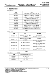
Product Descriptions and Part Numbers
1.1 コネクタ
Connectors
型番 Part Numbers
1717138-4
1717138-5
1717138-6
1717138-7
1612108-4
1746089-1
1717139-1
1827108-1
1827109-1
1674419-2
1903287-1
1939152-1
1939153-1
1981116-1
© Tyco Electronics Japan G.K.,
a TE Connectivity Ltd. Company
All Rights Reserved
タイコ エレクトロニクス ジャパン合同会社
(TE Connectivity Ltd.グループ)
TE logo is a trademark.
*Trademark
品名 Description
44 極プラグ・アッセンブリ (C)
44Pos Plug Assembly (C)
44 極プラグ・アッセンブリ (B)
44Pos Plug Assembly (B)
44 極プラグ・アッセンブリ (A)
44Pos Plug Assembly (A)
34 極プラグ・アッセンブリ(A)
34Pos Plug Assembly(A)
キャビティー・プラグ(埋め栓)
Cavity Plug
44 極ワイヤーカバー V タイプ
44Pos Wire Cover V Type
132 極キャップ・アッセンブリ
132Pos Cap Assembly
44 極ワイヤーカバー(A)
44Pos Wire Cover(A)
44 極ワイヤーカバー(B)
44Pos Wire Cover(B)
44 極ワイヤーカバー(C)
44Pos Wire Cover(C)
44 極ワイヤーカバー タイプⅣ
44Pos Wire Cover Type-IV
60 極プラグ・アッセンブリ
60Pos Plug Assembly
104 極キャップ・アッセンブリ
104Pos Cap Assembly
60 極キャップ・アッセンブリ
60Pos Cap Assembly
Fig.1
This is a Class II confidential document belonging to Tyco Electronics Japan G.K. A Class II
document may not be disclosed to any non-Tyco Electronics persons without (1) the written
approval of a Tyco Electronics manager and (2) the signing of a Confidential Disclosure
Agreement. この文書はタイコ エレクトロニクス ジャパン合同会社に帰属するクラス II 機密文
書です。クラス II 文書は(1)弊社の書面による承認 及び (2)機密保持合意書への署名なしに
社外へ公開することを許可しません。
Other products, logos, and company names might be trademarks of their respective owners.
1 of 20
LOC B
Instruction Sheet
取扱説明書
411-78121
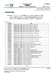
1.2 コンタクト
Contact
型番 Part
Numbers
1717148-1
1318329-1
1612776-1
1318332-1
1612775-1
Rev B2
品名
Description
クリーンボディー025 端子(S)
Clean Body 025 Contact (S)
クリーンボディー025 端子(M)
Clean Body 025 Contact (M)
クリーンボディー040 端子(S)
Clean Body 040 Contact (S)
クリーンボディー040 端子(M)
Clean Body 040 Contact (M)
クリーンボディー040 端子(CAN)
Clean Body 040 Contact (CAN)
Fig.2
適応電線
適応被覆外径
Applicable Wire
Applicable insulation
diameter
0.3―0.5mm2
1.1―1.7mm
0.5-0.85mm2
1.25―1.9mm
0.3―0.5mm2
1.25―1.7mm
0.75―1.25mm2
1.6―2.2mm
CAN 電線専用
CAN Wire Only
1.8―2.2mm
2 of 20
Instruction Sheet
取扱説明書
411-78121
1.3 製品の構成
CONTENTS
プラグ・アッセンブリ
Plug Assembly
040 メス端子
040 Female Contact
025 メス端子
025 Female Contact
ワイヤーカバー
Wire Cover
Fig.3
Fig.4
キャップ・アッセンブリ
Cap Assembly
Rev B2
3 of 20
Instruction Sheet
取扱説明書
411-78121
2. 顧客
顧客の
の受入検査
CUSTOMER RECEIVING INSPECTION
Tyco 品質管理規定により検査を行い、出荷に際しては完全なロット管理を行っていますが、受入検査
として少なくとも該当製品の顧客用図面の内容について、検査をすることが望まれます。
Tyco conducts inspections according to their quality control regulations to maintain an over
all lot control. In addition, the customers should conduct receiving inspections based on the
specific customer drawings.
3. 保管
保管および
および運搬時
および運搬時の
運搬時の取扱いについて
取扱いについて
STORAGE AND CARRYNG
3.1 端子
Contact
(1)梱包箱から出された状態での放置、運搬は避けて下さい。
(2)リールのフランジの面だけを持って運ばないで下さい。リールが破損し、圧着機にかからなくなります。
(1)Avoid receiving or carrying the contact reel in an open area without wrapping it in proper material.
(2)Do not lift up and carry the contact reel by gripping one the side of the reel, this may result
in damage to the reel and contacts before use.
Fig.5
横にして片側だけを持たない
Do not lift up laterally
holding one side only.
良い方法
Acceptable
(3)湿気の多い所には放置しないで下さい。直射日光にあたらない乾燥した清潔な屋内で、かつ常温常湿
(5~35℃,45~85%RH)の環境下に保管して下さい。
Avoid storing the contact reel in a moist or dusty place. Stock the reel in a comparatively dry
and clean place (5~35℃,45~85%RH) away from direct sunlight.
Rev B2
4 of 20
Instruction Sheet
取扱説明書
411-78121
(4)圧着機から一時取り外されたリールは、その先端の端子を適切な紐や針金によってフランジに結び、
リールがほどけない様にして下さい。
When removing the contact reel from the machine, fasten the end of the contact strip onto the
edge of the reel with use of proper string or wire. Fig 6.
結ぶ
Tie strip end with a wire neatly.
Fig.6
3.2 ハウジング
Housing
(1)直射日光にあたらない乾燥した清潔な屋内で、かつ常温常湿(5~35℃,45~85%RH)の環境下に保管
して下さい。
Avoid storing the contact reel in a moist or dusty place. Stock the reel in a comparatively dry
and clean place (5~35℃,45~85%RH) away from direct sunlight.
(2)露出状態での運搬や、長時間放置することは避けて下さい。
Avoid leaving or carrying the housing in an open area without wrapping it in proper material.
(3)運搬の際は、落下・衝撃を避けて下さい。
Do not drop or shock the housing when carrying it.
4. 圧着作業
CRIMPING OPARATION
圧着作業は、必ず当社指定の工具を使用いただき、指示された規程に従って、正しく実施して下さい。
Any crimping of contact must be performed by using appropriate Tyco tools according to
the applicable Instruction Sheet and Specification.
4.1 電線
Wire
4.1.1 適用電線
Applicable Wire
適用電線については、Fig.2を参照願います。
See Fig.2 for applicable wire.
Rev B2
5 of 20
Instruction Sheet
取扱説明書
411-78121
4.1.2 端末加工上の注意
Notes for Stripping Wire End
芯線に傷・切断・切欠き等がないように注意して下さい。
Wire end must be stripped without cut or damage of wire strands.
傷
Nick
切断
Cut off
切欠き
Damaged
Fig.7
不良
Defective
不良
Defective
不良
Defective
正常
Intact and Normal
Acceptable
Fig.7
使用する電線の絶縁被覆は滑らかなものを使用して下さい。圧着時に絶縁被覆表面に傷や変形のある
ものは使用しないで下さい。防水性能が低下する恐れがあります。
The wire must be using smooth insulation surface. Do not use the one that there is a wound
and deformation in the wire insulation surface when the contact crimping. There is fear that
the waterproof performance decreases.
4.2 圧着条件
Operation of Crimping Machine
下表の取付適用規格を、それぞれ参照願います。
See following Customer Manual for each contact.
Clean Body 025/040 端子
Clean Body 025/040 Contact
Rev B2
114-5278
6 of 20
Instruction Sheet
取扱説明書
411-78121
4.3 圧着端子の保管及び取扱いについて
Storage and Handling of Crimping Products
(1)乾燥した清潔な場所に保管して下さい。また、長期間にわたり露出状態で放置することは避けて
下さい。
Store the products in a clean, dry area cover with proper sheet or paper when placed in an
open area until the next day.
(2)束ねる場合は、端子のからみ・変形のない様に十分注意して下さい。
Care should be taken for tangle and deform of contacts in case of the leads should be in bands.
(3)多量に積み重ねると突起部が引っかかり、重量のために端子が変形し、接触不良、
端子保持力低下の原因となりますので、ご注意願います。
Do not stack the product so many layers. It makes electrical connection defective and low
contact retention force by catch together or by deform causing the weight of themselves.
(4)端子先端をそろえる為に、端子先端をたたいたり机面等に当てたりしないで下さい。
端子の変形が発生し、嵌合や性能に支障をきたす場合があります。
Must no hit tip of the contacts to coordinate the bundle. It makes mating or electrical defective.
Rev B2
7 of 20
Instruction Sheet
取扱説明書
411-78121
5. ハーネス製造作業
ハーネス製造作業
HARNESS MAKING
5.1 メス端子のハウジングへの挿入
Insertion Female Contact into Housing
(1)リテーナが仮係止状態にあることを確認して下さい。万一、本係止状態にある場合には仮係止
状態にした後に作業願います(Fig.8 参照)。本係止状態では端子が挿入できません。
Check Retainer is in pre-lock condition.(See Fig.8)The contact cannot be inserted in case
of the final lock condition.
仮係止状態
Pre-lock
Condition
リテーナー
Retainer
本係止状態
Final Lock Condition
Fig.8
Rev B2
8 of 20
Instruction Sheet
取扱説明書
411-78121
(2)Fig.9 のような向きにメス端子を指定のキャビティ(メス端子が収納される穴)に「カチッ」というランスの
装着音がするまで挿入して下さい。入り難い場合は無理に押し込もうとせずにリテーナーの位置を確認
して下さい。
Insert the contacts into the housing with same direction as shown in Fig. 9 The insertion
finished when you hear click sound and contact stops.
Please check the position of Retainer without pushing in by force, when it is hard to insert.
040 Contact
025 Contact
Fig.9
(3)更に電線を 20N 以下で引張り、端子が抜けてこないことを確認して下さい。
In addition to above action, confirm no extraction is made by puling wires with 20N max for contact.
注意
端子の挿入作業時、メスハウジング内にある一括防水用ゴム部品により、挿入力が通常
(非防水)コネクタより高めとなっております。挿入時には、端子がキャビティに突き当たるまで
確実に挿入し、ランスに係止されている事を確認願います。
NOTE
The contact performs higher insertion force than non-sealed type connector cause of
using family seal device. The contact especially requires careful insertion operation
specified by above-mentioned (2) and (3).
Rev B2
9 of 20
Instruction Sheet
取扱説明書
411-78121
5.2 ダブルロック(二重係止)作業
Retainer Final Lock (Secondary Lock)
(1) 全てのメス端子を挿入した後、リテーナーを確実に奥まで押し込み、本係止状態にします。
これで端子のダブルロックが完了です。
After all cavities are filled by inserted Contacts or Cavity Plugs properly, insert Retainers
into Housing to deep end and complete Final Lock condition.
ダブルロック作業前 (Before Retainer Insertion)
押す (Push)
)
(Pre-Lock Position)
ダブルロック作業後 (After Retainer Insertion)
リテーナー
Retainer
(Final Lock Position)
Fig.10
※ 挿入する際『パチッ』と音がするまで。且つ、図の様にリテーナ-が下に突き抜けていることを確認して下さい。
In case it inserts, until it make a clicking sound. And please check that retainer, it has run downward
as shown in a figure.
(2)リテーナーが押し込めない場合は、無理に押し込まず、メス端子の挿入不足がないか再度確認し、 完全に
挿入して下さい(Fig.10 参照)。挿入不足のメス端子がある場合、リテーナーを押し込むことができません。
When Retainers can not be inserted, do not operate with force and must find half insertion contact.
(Refer Fig.10) The half insertion contact prevents the retainers from inserting.
Rev B2
10 of 20
Instruction Sheet
取扱説明書
411-78121
5.3 ダブルロックの解除方法
Retainer Release Procedure
メス端子を挿入する場合や引き抜く場合は、リテーナーを仮係止状態にします。本係止状態では、挿入、
引き抜きはできません。
In case of Female Contact insertion or extraction, Retainer is extracted to Pre-Lock condition
(see Fig.10). It is impossible to insert or extract the contacts with Retainer final lock condition.
(1)シールを傷付けない様、充分に注意し、指又は適当な工具を用いてリテーナ-の突き出している部分を
押し、仮係止状態に戻す。
Push the retainer by finger or a tool then move it to Pre-Lock condition. And please be careful not
to damage the rubber then.
ダブルロック解除作業 (Pre-Lock Working )
押す(Push)
)
押す(Push)
)
拡大
(Detail)
Fig.11
Rev B2
11 of 20
Instruction Sheet
取扱説明書
411-78121
5.4 メス端子の引き抜き方法
Female Contact Extraction
(1) リテーナーが仮係止状態になっていることを確認します。万一、本係止状態になっている場合は、
仮係止状態にしてください(参照 Fig.10)。本係止状態では端子の引き抜きはできません。
Confirm Retainers are in Pre-Lock condition. In case of Final Lock condition, it is necessary
to move it to Pre-Lock condition(see Fig.10 ). It is impossible to extract the contacts under
Final Lock condition.
(2)専用冶具(P/N:1729919-1)でランスを軽く押しながら、電線を引張って端子を抜きます。
(端子を一度挿入方向に押込んでから上記の作業を行なうと、引抜き易くなります。)
Extract contact with pulling the crimped wire while pressing latch slightly with extraction
jig. (P/N:1729919-1) (It makes easier the operation that push the contacts to bottom end
of the cavities once before the operation above-mentioned).
拡大 (Detail
専用冶具挿入口
(Entrance of exclusive tool)
ランスが下がる。
(Lance is Fell.)
専用冶具
(Exclusive tool)
オス端子飛び込み間口
(Male Contact Insertion Window)
挿入方向
(Insertion Direction)
Fig.12
Rev B2
12 of 20
Instruction Sheet
取扱説明書
411-78121
注意
NOTE
注意
NOTE
Rev B2
端子の挿抜は同じ防水ゴムに対して3回までとし、それ以上挿抜を行なう際にはプラグ・
アッセンブリは必ず交換して下さい。
Plug Assembly must be exchanged for new one if insertion and separating
of contacts is to three times to the same rubber.
抜き治具をメス端子内部に挿入させないよう注意して下さい。万一、挿入させてしまった場合、再
使用せずに新品のメス端子と交換して下さい。
Do not insert the exclusive tool into inside of the female contact. In case of
the Insertion, no reuse is allowed and must be replaced with new female contact.
13 of 20
Instruction Sheet
取扱説明書
411-78121
5.5 キャビティプラグのハウジングへの挿入 (キャビティプラグを
キャビティプラグを取り付ける場合
ける場合のみ
場合のみ)
のみ)
)
Insertion Cavity Plug into Housing (Only in the case the cavity plug is attached.)
キャビティプラグは 025/040 サイズ共通で使用できます。
025 キャビティへは止まるまで、040 キャビティへは後端が飛び出ないよう、Fig.13 のようにキャビティプラグ
を挿入して下さい。
The cavity plug can be used for 025 and 040 sizes in common.
Insert the cavity plug in 025 cavities until stopping as shown in Fig.13.
Insert the cavity plug in 040 cavities until just withdrawing to the inside as shown in Fig.13.
注意
040 キャビティの奥までキャビティプラグを押し込み過ぎないようにして下さい。万一、
入れ過ぎた場合は、プラグ・アッセンブリは再使用せずに必ず交換して下さい。
NOTE
Do not push the cavity plug into the interior of 040 cavities too much. In case of
the Insertion, no reuse is allowed and Plug Assembly must be exchanged for
new one.
Fig.13
Rev B2
14 of 20
Instruction Sheet
取扱説明書
411-78121
5.6 ワイヤーカバーの取付け (ワイヤーカバーを
ワイヤーカバーを取付ける
取付ける場合
ける場合のみ
場合のみ)
のみ)
)
Wire Cover Attach Operation (Only in the case the wire cover is attached.)
(1)ワイヤーハーネスを引出方向に曲げる。
Bend wire harness to specified direction.
(2)カバーの後端をバックプレートに差し込む。ワイヤーカバーの背面側ロック部をプラグアッセンブリの
ロック係止用穴に挿入する。
Insert the back side lock of the Lever Assembly into hole for latch at Plug Assembly.
(3)差込を軸に回して反対のロックを閉じる。
It turns centering on a plug and close an opposite lock.
(4)ワイヤーカバーのヒンジを閉じる。ワイヤーカバーのワイヤー取出し側のワイヤーロック部(ヒンジ)を
ハーネスが漏れないことを確認してから締める。
Close the hook of the wire cover. Insert the wire taking out side lock of the Lever Assembly
into hole for latch at Plug Assembly.
(3)
(4)
Close the hook.
(2)
注意
Fig.14
ワイヤーハーネスがカバーからはみ出していないか、カバーに噛み込んでいないか等を確認
して下さい。
NOTE
No improper Wire Cover Attach Operation is allowed. Confirm wires are inside of the
Wire Cover neatly.
注意
レバー位置に注意して下さい。弊社出荷時のレバー位置にて、取付け作業をして下さい。
レバーアッセンブリの弊社出荷形態は Fig.16 を参照願います。
NOTE
Be aware Lever position. The operation should be done with same Lever position as
shipping condition. See Fig. 16 for Lever shipping condition.
Rev B2
15 of 20
Instruction Sheet
取扱説明書
411-78121
5.7 ハーネス製品の管理
Wire Harness Control
5.7.1 取扱いについて
Handling
コネクタや電線に無理な力を加えたり、衝撃を与えたりしないように十分注意して下さい。
Do not apply too much force or shock against connector or harness.
5.7.2 電線の結束やテーピングについて
Wire tie up and taping
束ね位置はコネクタ端面から 30mm 以上離し、かつ電線に無理な力がかからないように注意して下さい。
Wires are tied up at apart from 30mm more from the end of connector. The operation
be conducted carefully so that too much force is applied against the wires.
5.7.3 導通検査について
Conductivity Check
(1)導通検査に使用する治具は、相手側コネクタ又は同等のものを使用して下さい。
Use applicable mating connector or equivalent for conductivity check jig.
(2)メス端子内部に、検査用プローブを単独で絶対に挿入させないで下さい。
Check probe pin must not be inserted inside of female contact.
注意
NOTE
万一、挿入させてしまった場合、必ず新品のメス端子と交換して下さい。
Contact must be replaced in case of the prove pin insertion.
(3)導通検査用治具使用の際は弊社に御連絡下さい。
Contact Tyco if the check jig is required.
5.7.4 保管について
Storage
乾燥した清潔な場所に保管して下さい。また露出状態で長時間放置しないで下さい。
Store the product dry and clean area. In addition, do not leave the product with exposed condition.
5.7.5 出荷・運搬について
Shipping and Carrying
適正な梱包箱を利用し、塵埃、雨水等を防止し、丁寧に取扱うよう注意して下さい。
Use proper package which can prevent product from dust, rain, and etc. And handle carefully.
Rev B2
16 of 20
Instruction Sheet
取扱説明書
411-78121
6. コネクタ
コネクタの
の嵌合及び
嵌合及び離脱作業
Connector mating and unmating operation
同じマーク同士を確認した後、嵌合
Mate after confirm each same mark.
同様に
the same .
Fig.15
6.1 コネクタの嵌合
Connector Mating
(1)端子のハウジングへの装着状態、電線の束ね位置は正しいか、またリテーナーが本係止状態
になっていることを確認して下さい。仮係止状態になっている場合は本係止状態にして下さい。
(5.2 参照)。
Check contact latching condition, proper wire tie up position, and Retainer is in final lock
condition. Retainer must be adjusted to final condition if it is in initial lock condition.
(Refer par. 5.2)
(2) 次に、端子の変形、変色、傷、錆、ハウジングの変形、割れ、欠損、変色等の異常がないか確認して
下さい。
In the next step, check no contact has deformation, discolor, damage, rust and housing has
no deformation, crack, breakage, and discolor.
Rev B2
注意
万一、異常を発見した場合、必ず新品と交換して下さい。
NOTE
In case of any trouble is found, replace it to new one.
17 of 20
Instruction Sheet
取扱説明書
411-78121
(3)レバー位置の確認
Lever Position Confirmation
・レバーが初期位置にある事を確認して下さい。
Check Lever is at initial lock position.
・弊社出荷形態では、嵌合終了位置です。Fig.16 の通り、レバーを初期位置に移動させて下さい。
Tyco ships the product with Lever at mating complete position. Change it to initial position as
shown Fig. 16.
レバー初期位置 (Lever at initial position)
レバー嵌合終了位置 (Lever at mating complete position)
Fig.16
(4)コネクタを仮係止する。
プラグハウジングをオス側に Fig.15 の方向で真っ直ぐ挿入して下さい。それ以上押し込むことが
できなければ仮係止位置です。
Connector Pre-lock Operation
Insert female housing straight in male housing with specified direction by Fig.15. It is at
connector pre-lock condition when the female housing can not be inserted further more.
注意
NOTE
注意
NOTE
注意
NOTE
Rev B2
挿入時は絶対にコネクタをこじらない(挿入方向以外に力を加えない)よう注意して下さい。
At the insertion operation, no Kojiri (apply force except insertion direction) must be made.
ハーネス、プラグコネクタに無理な力を与えないで下さい。
Must not apply too much force against harness or female housing.
プラグコネクタを仮係止位置まで押込まずにレバー操作を開始すると、正常な嵌合が
出来ない恐れがあります。この様な時は、(3)の作業からやり直して下さい。
Normal mating operation may not be made if the operation is started under Incomplete
pre-lock operation. The operation must be returned to (3).
18 of 20
Instruction Sheet
取扱説明書
411-78121
(5)コネクタを嵌合する。
レバーを操作(回転)させて、レバー本係止部に確実にロックさせる。
この時、レバーのみを持つのではなく、プラグ本体をオス側に押し当てながら作業して下さい。
Make connector be mated.
Operate (rotate) Lever to the final lock position completely.
At this operation, do not handle Lever only but also pressing female housing to male housing.
コネクタ仮係止状態 (Connector Pre-lock position)
レバー嵌合終了位置 (Lever at mating complete position)
Fig.17
注意
NOTE
Rev B2
レバー操作中に引っ掛かり感があったり、スムーズに操作出来ない場合は、レバーを
初期位置に戻して、仮係止状態(奥まで押し当てた状態)として、再度作業し直して下さい。
In case of any unexpected feeling such as double action or unsmooth insertion during
the operation, Lever must be adjusted to at initial condition. Operation must be restart-ed.
And then return to (4) operation.
19 of 20
Instruction Sheet
取扱説明書
411-78121
6.2 コネクタの離脱
Connector unmating
(1)レバー本係止部を押し下げ、レバーのロックを解除する。
Release Lever lock by pressing down final lock device.
(2)レバーを操作(回転)させて、レバーを初期位置用係止部にロックする。
Lock Lever at initial lock device by operating (rotating) it.
(3)コネクタをオス側から引抜く。
Release female housing from male housing.
解除レバー
(Release Lever)
Fig.18
押しながらロックを解除する。
(Release Lever lock by pressing down)
レバー嵌合終了位置 (Lever at mating complete position)
レバー初期位置 (Lever at initial position)
Fig.19
Rev B2
20 of 20