1
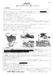
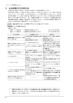
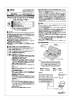
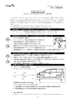
2015年1月 M56Y01-0
INSTALLATION MANUAL
ハイキャスロックⅡ タイプB
HICAS LOCK II TYPE B
品
番
56000 S210
Part Number
適
合
Application
HICASⅡ
SUPER HICAS
電動 ELECTRICAL SUPER HICAS
●KS13 SILVIA
●KRS13 180SX
●HCC33 LAUREL
●CA31 CEFIRO
●KPS13 SILVIA
●KRPS13 180SX
●HCR32 SKYLINE GTS
●BNR32 SKYLINE GT-R
●(G)CZ32 FAIRLADY Z (300ZX)
EARLY (~93.3)
●PBY32
CEDRIC/ GLORIA
●ECR33 SKYLINE GTS/GTS25t
●BCNR33 SKYLINE GT-R
●CS14
SILVIA
●S15
SILVIA
●(G)CZ32 FAIRLADY Z - LATE(93.3~)
●HBY33 CEDRIC/ GLORIA
●GCC34 LAUREL
●ER34
SKYLINE 25GT-T
日本語・・・・・・・・・・・・・・2p
English・・・・・・・・・・・・・13p
●この取扱説明書を良く読んでからお使いください
●”ハイキャスコンピューター配置図”とあわせてお使いください
●取り付け後も大切に保管してください
●販売店様で取り付けをされる場合は本書を必ずお客様へお渡しください
TOMEI製品のお買いあげありがとうございます。
ハイキャスロックⅡは車両のハイキャス機能を、電子回路(電気)とアクチュエーター(機械)の
2系統で完全に停止させることで、リアの剛性不足(フニャフニャ感)を解消。
FRの特性を最大限に生かしたダイナミックな走行が可能になります。
●
●
●
●
Please carefully read this manual prior to installation.
Please also refer to the MAZDA Service Manual with this Manual.
After the installation has been completed please keep this manual for future reference.
If the install was done in a shop please make sure to give this manual to the owner.
Thank you for purchasing a TOMEI quality product.
The HICAS & HICAS II LOCK will control the vehicles electrical (electronics) and actuators
(mechanical) system of the HICAS system.
This will eliminate the feel of lack of ridgity in the rear (limp feeling). The dynamic driving
characteristics will greatly improve with enhanced feedback to bring out the best from
your RWD car.
1
注意
■取扱説明書を良く読んで取り付けを行ってください。
■本品は自動車競技専用品です。サーキットか、公道から閉鎖されたコース内に限って使用してください。
■一般公道で使用すると車両本来の安全性が失われ危険です。
■本品は標準状態の車両(ハイキャスが作動する車両)とは旋回時の特性が変化します。
慣れるまで安全な場所で練習してからお使いください。
部品構成
キットに付属されている内容は下記の通りです。 ( )内は数量です。
ビス(2[予備のビス1])
両面テープ
(1)
ユニット (1)
シム (2)
タイラップ[小]
(1)
タイラップ[大]
(2)
オスコネクター (2)
取扱説明書
保証書
メスコネクター (2)
取扱説明書/保証書 (各1)
ハイキャスコンピューター配置図
ハイキャスコンピューター
後輪
シリンダー
ハイキャスロックユニット
ハイキャスロックシム
ハイキャスロックシム
2
作業に必要な工具類
取り付けには下記が必要です。
マイナスドライバー[大] 1
プラスドライバー[小] 1本
ニッパー
プライヤー
エレクトロタップかしめ用
モンキーレンチ 2本
電工圧着ペンチ
ジャッキ、リジットラック
メカニカルロック
取り付け準備
【車両設置】
車両下側の作業ができるように車両を設置してください。
警告
車両が不安定な状態で作業すると、車両が落下します。
リフトやピットを使用するか、ジャッキで車両を上げた後、 リジットラックで固定してください。
【ブーツ外し】
作業の箇所は後輪部分です。
シリンダーの位置など確認してください。
クランプ
シリンダー
ブーツ
シリンダー
クランプを外してください。
外したクランプは使用しません。
後輪
ブーツの内側のつけ根を外し、
ブーツを外側に移動させてください。
3
シムの取り付け
※ 電動スーパーハイキャス車
①左右のナットにモンキーレンチをかけ、
両方のナットを6ミリほど緩めてください。
警告
ナットは緩めすぎると外れます。
ナットは外れてしまうと、再び取り付けることが
できなくなることがあります。
緩めすぎないように注意し、絶対にナットを外さないでください。
6ミリ
6ミリ
シリンダー
ナット
②シムのビスを一旦外してシムを分割し、下図の箇所にシムを差し込んでください。
シム
シム
シム
シム
③シムをビスで固定してください。
ビス
ビス
ビス
ビス
4
右側(または左側) シムの取り付け
※ハイキャスⅡ、スーパーハイキャス車共通
①左右のナットにモンキーレンチをかけ、
どちらか一方のナットを6ミリほど緩めてください。
警告
緩める側と逆のナットをレンチで固定
6ミリ
シリンダー
ナットは緩めすぎると外れます。
ナットは外れてしまうと、再び取り付けることが
できなくなることがあります。
緩めすぎないように注意し、絶対にナットを外さないでください。
※片側が緩むと反対側は空回りします。
ナット
②シムのビスを一旦外してシムを分割し、下図の箇所にシムを差し込んでください。
シム
シム
③シムをビスで固定してください。
ビス
ビス
シリンダーのロッド
ハイキャスⅡ、スーパーハイキャス車にシムを
取り付けた場合、シムの内径がシリンダーのロッドの
外径より2~3ミリ大きいため、ガタがあります。
ただし、機能上の問題はありません。
シム
ガタ(2~3ミリ)
5
左側(または右側) シム取り付け
5ページにて、シムを取り付けた逆側にもシムをはさむ為の、すき間を確保します。
●車両の”自己診断機能”を利用して、パワーシリンダーを動かします。
自己診断機能……ハイキャスが動くか、動かないか点検する方法
・ステアリングボスを交換している場合は、ご使用のボスがハイキャス対応タイプか確認してください。
ハイキャス対応タイプでは無い場合、パワーシリンダーは動きませんのでノーマルステアリングに交換してください。
・この作業にはステアリングを切る人と、シムを入れる人の2人による作業になります。
・片側のシムを入れた段階で、反対側へもシムを挿入できる隙間がある場合は、
この機能を利用する必要はありません。
ハイキャスⅡ車両の場合
①電磁バルブのコネクターを外してください。
コネクター色 : 茶 色
ピン : 2 極
②エンジンをかけてください。
③シムを入れた方にステアリングを
めいいっぱい切ってください。
リアが動き、シムを入れていない側の隙間が開きます。
※左図は5ページの作業で最初に右側のシムを入れ、
左側の隙間を開ける場合のステアリング操作です。
めいいっぱい
開く
シム
④シムのビスを一旦外し、シムを分割してください。
⑤シムを差し込んでビスで固定してください。
シム
シリンダー
ビス
ビス
6
スーパーハイキャスの車両の場合
①エンジンを切ったまま、ギヤをニュートラル(AT車はP)に入れて、サイドブレーキを引いてください。
②ステアリングを直進にしてください。
③次の操作を、エンジン始動後10秒以内に行います
(1) エンジンをかける
(2) ステアリングを左右に“それぞれ5回”以上、20度以上 の角度で回す
(3) ブレーキを“5回”以上、踏む
これらは必ず順番に行って下さい。
【ステアリング】 【ブレーキ】 左右に“それぞれ5回”以上回す。(20度以上)
“5回”以上踏む。
①
②
左へ
右へ
①
②
③
④
③
⑤
④
⑥
⑤
20度以上の角度で
④エンジンを2000rpm以上に上げてください。
⑤シムを入れた方にステアリングを180度以上
切ってください。
リアが動き、シムを入れていない側の隙間が開きます。
※左図は5ページの作業で最初に右側のシムを入れ、
左側の隙間を開ける場合のステアリング操作です。
180度以上
開く
⑥シムのビスを一旦外し、シムを分割してください。
⑦シムを差し込んでビスで固定してください。
シム
シム
シリンダー
ビス
ビス
7
車両復帰
①パワーシリンダーを戻します。
②エンジンを止めて下さい。
③左右のナットをモンキーレンチを用いて、
締め付けてください。
ナットの頂部がシムのビスに当たらない様に、シムの位置を調整してください。
ナット
当たる
隙間
ビス
シム
④シムにブーツをかぶせ、タイラップ[大] で固定してください。
注意
ブーツをかぶせる際は、先のとがっていない工具などを
利用して、こじってください。
また、ブーツがやぶれないよう注意が必要です。
⑤車両を床に下ろしてください。
ホイールアライメント調整
ハイキャスロックのシムを取り付けると、わずかにトーインが付きます。
適当なトーインは直進安定性の確保に必要ですが、大きい場合はタイヤの偏摩耗を
招きます。シムの取り付けで付くトーイン量はわずかですが、作業後はトーインを測定し、
調整を行ってください。
トーイン=後側距離-前側距離
8
エレクトリカル(電気的)ロック
電磁バルブ コネクター外し
①イグニッションスイッチをOFFにし、バッテリーのマイナス端子を外してください。
②下図にしたがって、コネクターを外す、または接続してください。
③コネクターを外す車両の場合は、外したコネクターにゴミが入らないよう、
ビニールテー プなどで被服してください。
S13, RS13, A31, C33
電磁バルブ
PS13, RPS13
コネクター色:茶色 ピン数:2極
電磁バルブ
コネクター色:灰色 ピン数:3極
はずす
つなぐ
R32
Z32 M/C(マイナーチェンジ)前
電磁バルブ
コネクター色:灰色 ピン数:3極
電磁バルブ
コネクター色:灰色 ピン数:3極
はずす
はずす
Y32
電磁バルブ
S14, S15, R33, Z32 M/C後, C34, Y33, ER34
コネクター色:灰色 ピン数:3極
電磁バルブ
左前輪の前、カバーの内側
コネクター色:灰色 ピン数:3極
後輪下側
はずす
はずす
9
ユニット取り付け
ハイキャス
コンピューター
①ハイキャスコンピューターを探してください。
別紙の“ハイキャスコンピューター配置図”から、
ハイキャスコンピューターの位置を確認してしてください。
②配線を選別してください。
別紙の“ハイキャスコンピューター配置図”から、
コード3本を選別してください。
電源コード
信号コードA
信号コードB
③下記のとおり、配線を接続してください。
①電源コード
切断
ハイキャス
コンピューター
②信号コードA
切断
③信号コードB
□ ▽
記号解説
▽ □
△ □
青
□ △
白
赤
黒
黄
■ エレクトロタップ
△ オスギボシ
□ メスギボシ
(1)電源コードに、ユニットの赤コードをユニットのエレクトロタップで接続してください。
(2)信号コードAを切断し、コンピューター側にメスギボシを、車両側にオスギボシをかしめてください。
かしめたメスギボシにユニットの青線を、また、オスギボシにユニットの白線を接続してください。
(3)信号コードBを切断し、コンピューター側にオスギボシを車両側にメスギボシをかしめてください。
かしめたオスギボシにユニットの黒線を、また、メスギボシにユニットの黄線を接続してください。
(4)配線をタイラップ[小]で束ね、ユニットを任意の場所に両面テープで固定してください。
(5)バッテリーのマイナス端子を接続してください。
10
保証書とサービス
注意
■本品は保証書を添付しています。保書証は取扱説明書と一緒に保管してください。
(保証書の再発行は実施いたしませんので、大切に保管してください。)
■保証書は販売店で所定事項を記入してもらうか、購入時のレシートを一緒に保管して、購入した販売店と日付が
確認できるようにしておいてください。
■保証の条件は保証書に記載いたしましたので、内容を良くお読みください。
■外観上の変化(傷等)や、消耗品、取り外したことにより再使用できなくなった部品(タイラップ)は保証できません。
■保証期間経過後の修理については、販売店か当社までご相談ください。
修理によって機能が維持できる場合は、お客様のご希望により有償修理致します。
11
12
CAUTION
■ Please thoroughly read the attached installation manual.
■ These products are designed to be used for off road competition purposes only.
■ This product is NOT for use on public roads, due to safety risks and may not be road legal in your area.
■ This product will change the vehicles (that are fitted with HICAS) driving and turning characteristics.
Please test the vehicle in a safe off public road environment to get used to the new feel of the car.
KIT CONTENTS
Below is the contents of this kit with the quantity listed in brackets ().
Screws (2 [with 1 spare])
DOUBLE SIDED TAPE (1)
For the Unit
UNIT (1)
SHIM (2)
Cable Ties [Large] (2)
for securing the boots.
Cable Tie [small] (1) for wiring
Male Connector (2)
Installation
Manual
Warranty
Female Connectors (2)
Installation Manual /
Warranty Card (1 each)
HICAS Computer
Location Manual (1)
HICAS Computer
Rear
Wheels
Cylinder
HICAS Lock Unit
HICAS Lock Shim
HICAS Lock Shim
13
REQUIRED TOOLS
These tools are the bare minimum required for the job.
Flathead Screw Driver
[Large] 1
Nipper
Phillips-Head Screwdriver
[Small] 1
Monkey Wrench x2
Pliers
Electrical Crimping Pliers
Jack Stands & Floor Jack
MECHANICAL LOCK
Installation Preparation
【Vehicle Installation】
Have the vehicle setup so you can work under the vehicle.
WARNING
When working with an unstable vehicle, will increase the risk
factor of the vehicle dropping on you.
Use a lift or a pit to safely gain access to areas under the car,
Please use a fixed rigid car stand if required.
【Boots Removal】
You'll be working on the rear wheels.
Check the positions of the cylinders, etc.
Clamp
Cylinder
Boots
Cylinder
Remove the clamp
Do not reuse the clamp
Rear
Pull back the boots far enough to reveal the nut.
14
SHIM INSTALLATION
※ Cars with Electric Super HICAS
①Use the monkey wrenches on the nuts on both sides
to loosen them about 6mm.
WARNING
Be careful not to loosen the nut too much.
You do not want the nut to come off.
If the nut comes off, it may be impossible
to reinstall it. So never remove the nut.
6mm,
6mm
Cylinder
Nut
② Take the shims apart and then install them as shown in the illustration below.
Shim
Shim
Shim
Shim
③ Secure the Shims in place with the screws.
Screw
Screw
Screw
Screw
15
RIGHT SIDE (THEN LEFT SIDE) SHIM INSTALLATION
※ Same for both HICAS II & Super HICAS
① Use monkey wrenches on both nuts to hold the right
and loosen the left side. Loosen the nut about 6 mm.
WARNING
Hold the nut with a wrench in place to
loosen the nut on the opposite side.
6mm
Cylinder
Be careful not to loosen the nut too much.
You do not want the nut to come off.
If the nut comes off, it may be impossible
to reinstall it. So never remove the nut.
※ Leave the opposite side as normal.
Nut
② Leave the other side as normal. Separate the Shims and then install as shown below.
Shim
Shim
③ Secure the Shims in place with the Screws.
Screw
Screw
Cylinder Rod
The HICAS II and Super HICAS, shims have
a 2-3mm larger inner diameter than the rods
cylinder bore of the Shim. This will have a
backlash, but it poses no functional problems.
Shim
Play (2~3mm)
16
LEFT SIDE (THEN RIGHT SIDE) SHIM INSTALLATION
Page 5 contains the opposite sides clearance for the Shims.
●Vehicle "Self-Diagnostics", move the power cylinder.
Self-Diagnostics.... What HICAS moves and how to verify the job.
・When changing your steering wheel boss, check to make sure it's the HICAS compatible type.
If it's not compatible, then change the steering wheel to the stock standard one to get it working.
・This is done with 2 people, 1 at the steering wheel, and the other working with the Shims.
・Install a Shim on one side, then if there's enough gap to insert the shim on the other side,
then you won't need to do this.
For vehicles equipped with HICAS II
① Remove the Solenoid Valve Connector.
Connector Color: Brown
Pin : 2 Pole
② Start the Engine.
③ Turn the steering wheel full lock to the side
where you had installed the shim
The cylinder will move and the gap will widen
on the other side.
※As shown on the illustration on page 16,
you install the shim on the right side first.
Then you can make the gap wider with the
steering wheel.
Full Lock
Open
Shim
④ Separate the Shims to install them in place.
⑤ Use the screws to secure the shims in place.
Shim
Cylinder
Screw
Screw
17
VEHICLES WITH SUPER HICAS
① Have the engine turned off and the gear in neutral (AT cars in P). Have the Handbrake/E Brake on.
② Then position the steering wheel to the center.
③ Perform the following operations within the first 10seconds after the engine starts
(1) Start the engine
(2) Turn the steering wheel from side to side, at least "5 times each side", turning the steering wheel
at least at 20 degrees.
(3) Turn the steering wheel 5 times as shown below, and then Pump the brake (at least 5 times) afterwards.
Please be sure to perform in the order as shown.
【STEERING】 【BRAKE】 5 times each for both left and right. (At least 20 degrees)
Step on the pedal 5 times.
①
②
Left
Right
①
②
③
④
③
⑤
④
⑥
⑤
Turn at least 20 degrees on each side.
④ Raise the engine rpm above 2000rpm.
⑤ Turn the steering wheel more than 180 degrees to
install a Shim. Allow movement of the rear open
side. This gap does not require a Shim.
※As shown on the illustration on page 16,
you install the shim on the right side first.
Then you can make the gap wider with the
steering wheel.
Turn at least 180 degrees
Open
⑥ Separate the Shims to install them.
⑦ Use the screws to secure it in place once fitted.
Shim
Shim
Cylinder
Screw
Screw
18
INSTALLATION VERIFICATION
① Re-install the power cylinder.
② Turn off the engine.
③ Fix in place by using both wrenches to tighten
both nuts.
Adjust and position the shim so that the nut will not cover the screws on the shims.
Nut
Contact
Correct
Clearance
Screw
Shim
④ Fit the boots over the shim, and tie in place with the large
cable tie.
CAUTION
When covering the boots, use a blunt tool to aid with
positioning the boot in place.
Take care not to damage or tear the boots.
⑤ Safely lower the vehicle.
WHEEL ALIGNMENT
If you install a shim HICAS lock, your toe settings will be affected.
Correction to your toe settings will be required to correct your steering alignment, this
will prevent uneven wear on your tires.
The amount of toe-in will have changed due to the installation of the shims.
A professional wheel alignment will correct this.
Toe-in = Heel Gap-Toe Gap
19
ELECTRICAL LOCK
REMOVAL OF THE SOLENOID CONNECTOR
① Turn OFF the ignition, disconnect the battery's negative terminal.
② Follow the diagrams below to disconnect and reconnect the connector.
③ If the connected is to be left disconnected, wrap it with vinyl electrical tape
to protect it from unwanted dirt and grime.
S13, RS13, A31, C33
Soleniod
PS13, RPS13
Connector Color: Brown PIN #: 2
Soleniod
Connector Color: Grey PIN #: 3
Disconnect
Connect
R32
Soleniod
Z32 (Late Model)
Connector Color: Grey PIN #: 3
Soleniod
Connector Color: Grey PIN #: 3
Disconnect
Disconnect
Y32
Soleniod
S14, S15, R33, Z32 Late, C34, Y33, ER34
Connector Color: Grey PIN #: 3
Soleniod
In front of the left front wheel, the inside the cover
Connector Color: Grey PIN #: 3
Behind the HICAS cylinder.
Disconnect
Disconnect
20
UNIT INSTALLATION
HICAS
Computer
① Locate the HICAS computer.
Check on the separate "HICAS Computer Information"
documentation for the location of the HICAS computer.
②Check the wiring.
Check the 3rd wire as per reference on the supplied "
HICAS Computer Information" documentation.
Power
Wire A
Wire B
③ Follow the illustration below for the correct wiring method.
① Power
Cut
HICAS
Computer
② Wire A
Cut
③ Wire B
□ ▽
▽ □
Red
Symbol Keys
△ □
Blue
□
White
△
Black
Yellow
■ Electro-Tap
△ Male Connector
□ Female Connector
(1) Connect the red power wire to the vehicles HICAS ECU power wire with the supplied Electro Tap.
(2) Cut wire A, and connect the male connector on the vehicle side and the female connector on the
computer side . The Blue Hicas Lock unit's wire with the male connector then connects to the female
connector is then to be connector on the computer side (that you have just made).
The White wire then connects to the vehicle side male connector.
(3) Cut Wire B, and connect the female connector on the vehicle side and the male connector on the
computer side. Then connect the Black Hicas Unit wire with the female connector on the computer sides
male connector (that you have just made).
The Hicas Units Yellow wire male connector is then to be connected to the vehicle side female
connector (that you have just made).
(4) Use the small cable tie to keep it tidy and use the double sided tape to secure the unit in your
chosen location.
(5) Connect the battery's negative terminal.
21
WARRANTY & SERVICE
CAUTION
■ This product comes with a limited warranty cover. The Warranty card should be found supplied with this manual.
(Tomei WILL NOT re-issue another warranty card, so please keep it safe.)
■ The Warranty card is to be completed with the dealers details (by the dealer) from whom you had purchased
the product from. You'll need to keep the warranty card with the original purchase receipt showing the date of
purchase in case you need to make a claim.
■ Read the Warranty card terms in detail to know what we do and do not cover.
■ The limited Warranty does NOT cover claims in requires to changes in the product appearance with later product
revisions, scratches and cosmetic blemishes, general wear from usage. If the product(s) has been tampered with,
altered in anyway, it will void the "Limited Warranty" immediately.
■ For any Warranty claims during the "Limited Warranty" coverage period, you will have to contact and notify the
dealer/shop whom you had purchased our product from to initiate the Warranty claim. Specific requests for
repairs/replacements by the customer is to be paid for separately by the customer and will not be covered by the
"Limited Warranty" coverage.
22
23
株式会社 東名パワード
〒194-0004 東京都町田市鶴間1737-3
TEL : 042-795-8411(代)
FAX : 042-799-7851
1737-3 Tsuruma Machida-shi Tokyo 194-0004 JAPAN
TEL : +81-42-795-8411(main switchboard)
FAX : +81-42-799-7851
http://www.tomei-p.co.jp
この製品に関わる取り付け、操作上のご相談は上記へお願いします。
営業時間:月~金(祝祭日、年末年始を除く)9:00~18:00
If you have any questions in regards to the installation of this product,
please contact your local authorized Tomei Powered distributor.
OPEN: Monday - Friday (National holidays and public holidays excluded). 09:00 - 18:00
2015年1月 ハイキャスロック取扱説明書 M56Y01-0
HICAS LOCK INSTALLATION MANUAL 2015.1 M56Y01-0
24