1
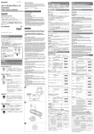
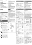
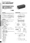
日本語 3-863-799-05 (1) English A カメラ設置上のご注意 下記の注意事項を守らないと、けがをしたり周辺の物品に損害を与え ることがあります。 内部に水や異物を入れない 水や異物が入ると、火災の原因となります。 万一、水や異物が入ったときは、すぐに本機が接続されている電 源供給機器の電源を切り、DC電源ケーブルや接続ケーブルを抜 いて、お買い上げ店にご相談ください。 Black-and-White Video Camera Module 分解しない、改造しない 分解や改造をすると、火災やけがの原因となります。 点検および修理は、お買い上げ店にご依頼ください。 カメラケーブルを傷つけない 取扱説明書 カメラケーブルを傷つけると、火災や故障の原因となることがあ ります。次の項目をお守りください。 ˎˎ 設置時に、製品と壁やラック、棚などの間に、はさみ込まない。 ˎˎ カメラケーブルを加工したり、傷つけたりしない。 ˎˎ 重いものをのせたり、引っ張ったりしない。 ˎˎ 熱器具に近づけたり、加熱したりしない。 ˎˎ カメラケーブルを抜くときは、必ずプラグを持って抜く。 芯線の露出や断線などでカメラケーブルが傷んだら、お買い上げ 店に交換をご依頼ください。そのまま使用すると、火災の原因と なります。 Operating Instructions お買い上げいただきありがとうございます。 電気製品は、安全のための注意事項を守らないと、 けがをしたり周辺の物 品に損害を与えることがあります。 この取扱説明書には、 事故を防ぐための重要な注意事項と製品の取り扱いかたを示してあ ります。この取扱説明書をよくお読みのうえ、製品を安全にお使いください。お読みになっ たあとは、いつでも見られるところに必ず保管してください。 XC-56BB 設置は確実に 設置については、必ずお買い上げ店にご相談ください。 壁面や天井などへの設置は、本機と取り付け金具を含む重量に充 分耐えられる強度があることをお確かめください。充分な強度 がないと、落下して、大けがの原因となります。 また、1年に1度は、取り付けがゆるんでいないことを点検して ください。 指定された電源を使う © 2004 Sony Corporation Printed in Japan この取扱説明書に記されている電源供給機器(カメラアダプター など)でお使いください。規定外の電源でのご使用は、火災の原 因となることがあります。 A 指定されたカメラケーブル、接続ケーブルを使う モニター / Monitor この取扱説明書に記されているカメラケーブル、接続ケーブルを 使わないと、火災や故障の原因となることがあります。 カメラ設置の際は、周辺機器を含めてカメラに接続されている各機器間で接地電位の 差が生じないようにしてください。接地電位差により故障の原因となる場合がありま す。設置の都合により電位差を生ずる場合は、機器の内いずれかひとつの機器だけを接 地するようにしてください。 使用上のご注意 カメラ / Camera 異常電流/ Abnormal electricity GND2 The model and serial numbers are located on the bottom. Record the serial number in the space provided below. Refer to these numbers whenever you call upon your Sony dealer regarding this product. GND1 Model No. XC-56BB Important Safety Instructions (接地電位差)/ ˎˎRead these instructions. ˎˎKeep these instructions. ˎˎHeed all warnings. ˎˎFollow all instructions. ˎˎDo not use this apparatus near water. ˎˎClean only with dry cloth. ˎˎDo not block any ventilation openings. Install in accordance with the manufacturer’s instructions. ˎˎDo not install near any heat sources such as radiators, heat registers, stoves, or other apparatus (including amplifiers) that produce heat. ˎˎOnly use attachments/accessories specified by the manufacturer. ˎˎRefer all servicing to qualified service personnel. Servicing is required when the apparatus has been damaged in any way, such as power-supply cord or plug is damaged, liquid has been spilled or objects have fallen into the apparatus, the apparatus has been exposed to rain or moisture, does not operate normally, or has been dropped. (Ground electric potential difference) B Serial No. ______________ WARNING To reduce the risk of fire or electric shock, do not expose this apparatus to rain or moisture. C XC-56BB DC-700 WEN HD 1 2 TRIG VIDEO 1 CAMERA AC IN 2 VD/SYNC The camera operates on +12 V DC. Use a stable power source free from ripple or noise. Foreign bodies 使用・保管場所 Be careful not to spill liquids, or drop any flammable or metal objects in the camera body. 次のような場所での使用および保管はお避けください。 ˎˎ 極端に暑い所や寒い所。適正使用温度は0∼40℃です。 ˎˎ 激しい振動のある所。 ˎˎ 強力な電波を発生するテレビ、ラジオの送信所の近く。 Locations for operation and storage Avoid operation or storage in the following places. お手入れ レンズや光学フィルターの表面に付着したごみやほこりは、ブロアーで払ってくださ い。外装の汚れは、乾いた柔らかい布でふきとります。ひどい汚れは、中性洗剤溶液を 少し含ませた布でふきとった後、からぶきします。アルコール、ベンジンなどは、変質し たり塗料がはげることがありますので、使用しないでください。 レーザービームについてのご注意 レーザービームはCCDに損傷を与えることがあります。レーザービームを使用した 撮影環境では、CCD 表面にレーザービームが照射されないように充分注意してくだ さい。 概要 D Note on laser beams XC-56BBは固体撮像素子CCD(Charge Coupled Device)を採用した白黒ビデオカメ ラモジュールです。 高画質 VGA対応の33万画素CCDにより、VGA相当(647×493画素)のきめ細かな画像を再現 します。また正方画素CCDの採用により、画像処理時のアスペクト比変換は不要です。 多様なモード設定 外部同期 ˎˎGain: Fix/Manual ˎˎRead mode: normal (30 fps)/binning (60 fps) ˎˎPartial Scan ˎˎSynchronized input/output ˎˎ75-ohm termination ˎˎShutter: Normal/Trigger shutter ˎˎShutter speed High image quality The progressive scan CCD (330,000 dots, VGA compliant) provides a high-resolution image with 647 × 493 pixels. By adopting square pixels, images can be processed using the original aspect ratio without a converting procedure. Various mode settings Rear panel switches allow the following mode settings. For customers in Europe For the customers in Europe The manufacturer of this product is Sony Corporation, 1-7-1 Konan, Minato-ku, Tokyo, Japan. The Authorized Representative for EMC and product safety is Sony Deutschland GmbH, Hedelfinger Strasse 61, 70327 Stuttgart, Germany. Pour les clients en Europe E 1 小突起/Small protrusion Le fabricant de ce produit est Sony Corporation, 1-7-1 Konan, Minato-ku, Tokyo, Japon. Le représentant autorisé pour EMC et la sécurité des produits est Sony Deutschland GmbH, Hedelfinger Strasse 61, 70327 Stuttgart, Allemagne. Fü Kunden in Europa Der Hersteller dieses Produkts ist Sony Corporation, 1-7-1 Konan, Minato-ku, Tokyo, Japan. Der autorisierte Repräsentant für EMV und Produktsicherheit ist Sony Deutschland GmbH, Hedelfinger Strasse 61, 70327 Stuttgart, Deutschland. ネジ/Screw コントロール部/Control unit 2 小突起/Small protrusion HD信号とVD信号は、リアパネルのスイッチを変更することにより、12ピンコネクター から出力させることができます。 電子シャッター FL(フリッカーレス)モードと豊富なシャッタースピード(1/125∼1/15000秒)の中か ら、撮影条件に合った速度が選べます。 外部トリガーシャッター機能(1/4∼1/100000秒) トリガーを入力することにより、1枚の静止画が得られます。高速で移動する物体を正 確にとらえます。 部分読み出し機能 有効な映像出力ライン数を限定することにより、高速な画像処理に適したフレーム レートの高い映像出力が得られます。 ビニング機能 垂直方向の2画素を混合した映像信号が60 度がほぼ2倍となります。 溝/Slit 筐体固定 筐体固定用のネジ穴がCCDの基準面が含まれているフロントパネルの下部にあります。 ここでカメラモジュールを固定すれば、光軸のずれを最小限にとどめることができます。 従来機XC-55BBと互換性のあるピン配置になっています。 B 構成 白黒ビデオカメラモジュールXC-56BBを中心としたシステムの構成品目は、次のとお りです。 白黒ビデオカメラモジュール For the customers in the U.S.A. SONY LIMITED WARRANTY - Please visit http://www.sony.com/psa/warranty for important information and complete terms and conditions of Sony’s limited warranty applicable to this product. SONY LIMITED WARRANTY - Please visit http://www.sonybiz.ca/solutions/ Support.do for important information and complete terms and conditions of Sony’s limited warranty applicable to this product. ネジ/Screw F For the customers in Europe Sony Professional Solutions Europe - Standard Warranty and Exceptions on Standard Warranty. Please visit http://www.pro.sony.eu/warranty for important information and complete terms and conditions. For the customers in Korea SONY LIMITED WARRANTY - Please visit http://bpeng.sony.co.kr/handler/ BPAS-Start for important information and complete terms and conditions of Sony’s limited warranty applicable to this product. ツメ/Pawl カメラケーブルCCXC-12P02N(2 m)/05N(5 m)/10N(10 m)/ ˎˎ 安全のための注意事項を守る。 ˎˎ 長期間、安全にお使いいただくために、定期点検をすることをおすすめします。点検 の内容や費用については、お買い上げ店にご相談ください。 お買い上げ店にご連絡ください。 ˎˎ 故障したら使わずに、 警告表示の意味 行為を禁止する記号 この取扱説明書および製品では、次のような表示を しています。表示の内容をよく理解してから本文を お読みください。 行為を指示する記号 この表示の注意事項を守らないと、火災 やその他 の事故によりけがをしたり周辺の物品に損害を 与えたりすることがあります。 Shutter speed can be selected from a wide range (1/125 to 1/15000 sec.) or in flickerless (FL) mode. External trigger shutter function (1/4 to 1/100000 sec.) You can obtain a freeze picture by inputting an external trigger. This function is useful to shoot a fast-moving object clearly. Partial Scan The camera module can limit the number of effective video output lines to achieve high frame rates, enabling high-speed image processing. By “binning” two pixels that align vertically, you can acquire sensitivity twice as high as that in the normal mode, and a frame rate of 60 fps. Body fixing The screw holes to install the camera module are located under the front panel (the CCD reference plane). Installing the camera module on the front panel minimizes deviation of the optical axis. B The Black-and-White Video Camera Module XC-56BB system comprises the following products. XC-56BB専用ケーブル(2m) Cマウントレンズ CCXC-12P02N (2 m, 6.6 ft)/05N (5 m, 16.4 ft)/10N (10 m, 32.8 ft)/25N (25 m, 82 ft) Camera Cable NFマウントレンズ DC-700/700CE Camera Adaptor 推奨レンズ:VCL-03S12XM/06S12XM/12S12XM/12SXM Special cable for the XC-56BB (2 m, 6.6 ft) 接写リングセット LO-999ERK VCT-55I Tripod Adaptor (for CCU) Cマウントアダプター LO-999CMT VCT-333I Tripod Adaptor (for CHU) C・D 接続例 トリガーを入力してカメラを動作させる場合には、DC-700は使用できません。ジャ ンクションボックスJB-77と市販の安定化電源を用い、JB-77のCLOCK OUT端子にト リガーを入力してください。 カメラモジュールを、カメラアダプター DC-700を介して電源に接続します。カメラア ダプター DC-700の詳細については、DC-700の取扱説明書をご覧ください。 モニター 専用ケーブル 75 Ω同軸ケーブル カメラケーブル(CCXC-12P05Nなど) DC IN/SYNC端子 VIDEO 1端子へ CAMERA端子へ AC IN端子へ 同期信号発生器 Recommended lenses: VCL-12YM/50Y-M NF-mount lens Recommended lenses: VCL-03S12XM/06S12XM/12S12XM/12SXM LO-999CMT C-mount adaptor Connection example C.D If you intend to operate the camera using a trigger pulse, you cannot use the DC-700/700CE. Use the JB-77 Junction Box and a commercially available stable power source, and input a trigger pulse to the CLOCK OUT jack on the JB-77. AC電源へ HD端子へ VD/SYNC端子へ HD出力 VD出力 Connecting DC-700/700CE (not supplied) 1 (Fig. C) Connect the camera module to the power via the DC-700/700CE Camera Adaptor. For details on the DC-700/700CE Camera Adaptor, refer to the DC-700/700CE Instruction Manual. Monitor Special cable 75-ohm coaxial cable Camera cable (e.g. CCXC-12P05N) Sync signal generator DC-700(別売り)との接続例2(図D) DC-700 カメラケーブル(CCXC-12P05Nなど) XC-56BBコントロール部(CCU) 三脚アダプター(VCT-55I) 専用ケーブル XC-56BBヘッド部(CHU) 三脚アダプター(VCT-333I) Cマウントレンズアダプター(LO-999CMT) Cマウントレンズ Cマウントレンズをご利用いただく場合は、VCL-12YM、VCL-50Y-Mを装着可能で す。その他のレンズは本機の特性上、装着できません。 接写リングキット(LO-77ERK) NFマウントレンズ VCL-03S12XM/06S12XM/12S12XM/12SXMを装着可能です。 ご注意 XC-56BBのCHUとCCUは、同一シリアルナンバーでの組み合わせにてご使用くださ い。 XC-56BBにCマウントレンズを取り付ける際のご注意 ˎˎ Cマウントレンズを取り付ける場合はCマウントアダプター LO-999CMT(別売り) が必要です。Cマウントレンズはレンズマウント面からの飛び出し量が4.1mm以下 のものを使用してください。 4.1 mm以下 C-mount lens LO-999ERK Extension ring kit DC-700(別売り)との接続例1(図C) DC IN/SYNC connector To VIDEO 1 connector To CAMERA connector To - AC IN connector To AC power source To HD connector To VD/SYNC connector HD output VD output Connecting DC-700/700CE (not supplied) 2 (Fig. C) DC-700/700CE Camera cable (e.g. CCXC-12P05N) XC-56BB Camera Control Unit (CCU) VCT-55I (Tripod adaptor) Special cable XC-56BB Camera Head Unit (CHU) VCT-333I (Tripod adaptor) LO-999CMT C-mount adaptor C-mount lens If you use a C-mount lens, you can attach a VCL-12YM/VCL-50Y-M lens. Because of the unique characteristics of the XC-56BB, you cannot install any other type of lens. LO-77ERK Extension ring kit NF-mount lenses You can attach a VCL-03S12XM/06S12XM/12S12XM/12SXM lens. Note レンズマウント面 The XC-56BB CHU and CCU must have the same serial number combination. ˎˎ Cマウントアダプターをご使用時のカメラ設置については、カメラヘッドを固定せ ず、Cマウントレンズを固定して、無理な力がカメラヘッドにかからないようにご注 意ください。 ˎˎ 振動や衝撃の多いところでのCマウントアダプターご使用は破損、ゆるみなどの原因 になります。 Notes for installing the C-mount lens to the XC-56BB ˎˎTo install the C mount lens, you will need a C mount adaptor LO-999CMT (not supplied). The protrusion on the C mount lens must be 4.1mm (3/16 in.) or less from the lens mounted surface. 4.1mm or less (3/16 in.) XC-56BBにNFマウントレンズ(専用レンズ)を取り付ける際のご注意 Lens mounted surface VCL-7S12XEA(オートアイリスレンズ)は、取り付けることができません。 ヘッド部とコントロール部の接続 1 2 E 付属の専用ケーブルをコントロール部に接続します。コントロール部端子 上部の小突起とプラグの溝を合わせて充分に深く差し込んでからネジを 締め付けます。 もう一方のプラグを1と同じ要領でヘッド端子に接続します。 ˎˎ レンズを 取り扱うときはゴミや指紋がレンズ表面に付かないようにご注意くださ い。 ˎˎ 専用ケーブルのプラグ両端はコントロール部、ヘッド部のどちらに接続してもかま いません。 ˎˎ 故障の恐れがありますので通電中は専用ケーブルを抜き差ししないでください。 フェライトコアの取り付け(図F) ソニー製品は安全に充分に配慮して設計されています。しかし、まちがった使いかたを すると、火災や感電などにより死亡や大けがなど人身事故につながることがあり、危険 です。 事故を防ぐために次のことを必ずお守りください。 Electronic shutter function System Components カメラアダプター DC-700/700CE ご注意 安全のために You can output the HD and VD signals from the 12-pin connector by changing the rear panel switch. The pin assignment is compatible with the existing model, the XC-55BB. 25N(25 m) 接続が終わったら、まずモニターの電源を入れ、最後にカメラコントロールユニットの 電源を入れてください。 約150mm/About 150 mm Internal sync signal output The connector complies with the 12-pin assignment used by the XC-55BB. コントロール部(CCU)とヘッド部(CHU)に分かれています。 HD (horizontal drive), VD (vertical drive) signals: The camera module automatically detects the HD and VD signals input and externally synchronized with those signals. Binning XC-55BB互換の12ピンコネクターピンアサインメント For the customers in Canada ヘッド部/Head unit fpsで得られます。ノーマルモード比で感 External synchronization 推奨レンズ:VCL-12YM/50Y-M Cet appareil numérique de la classe B est conforme à la norme NMB-003 du Canada. 溝/Slit 内部同期信号出力 For the customers in the U.S.A. Pour les utilisateurs au Canada RB Before operating the unit, please read this manual thoroughly and retain for future reference. The camera module consists of Camera Control Unit (CCU) and Camera Head Unit (CHU). This camera is not intended for use in security applications in the meaning of the European standard series EN 50132 (Alarm systems - CCTV surveillance systems for use in security applications). Overview The XC-56BB is a monochrome video camera module using a progressive scan CCD (Charge Coupled Device) solid state image sensor. This Class B digital apparatus complies with Canadian ICES-003. Laser beams may damage a CCD. You are cautioned that the surface of a CCD should not be exposed to laser beam radiation in an environment where a laser beam device is used. リアパネルのスイッチの切り換えにより、以下のモード設定が可能です。 ˎˎ ゲイン : 固定/手動調整 ˎˎ 読み出しモード : ノーマル(30 fps)/ビニング(60 fps) ˎˎ 部分読み出し機能 ˎˎ 同期入出力 ˎˎ 75 Ω終端 ˎˎ シャッター機能 : ノーマル/トリガーシャッター ˎˎ シャッタースピード For customers in Canada Use a blower to remove dust from the surface of the lens or optical filter. Clean the exterior with a soft, dry cloth. If the camera is very grimy, apply a cloth soaked in a mild detergent then wipe with a dry cloth. Do not apply organic solvents such as alcohol or benzine which may damage the finish. 三脚アダプター VCT-333I(CHU用) This device complies with part 15 of the FCC Rules. Operation is subject to the following two conditions: (1) This device may not cause harmful interference, and (2) this device must accept any interference received, including interference that may cause undesired operation. Care Black-and-White Video Camera Module All interface cables used to connect peripherals must be shielded in order to comply with the limits for a digital device pursuant to Subpart B of part 15 of FCC Rules. ˎˎExtremely hot or cold locations. Recommended temperature range is 0°C to 40°C. (32°F to 104°F) ˎˎLocations subject to strong vibration ˎˎNear generators of strong electromagnetic radiation such as TV or radio transmitters. 三脚アダプター VCT-55I(CCU用) You are cautioned that any changes or modifications not expressly approved in this manual could void your authority to operate this equipment. Notes on Operation To avoid electrical shock, do not open the cabinet. Refer servicing to qualified personnel only. This equipment has been tested and found to comply with the limits for a Class B digital device, pursuant to part 15 of the FCC Rules. These limits are designed to provide reasonable protection against harmful interference in a residential installation. This equipment generates, uses and can radiate radio frequency energy and, if not installed and used in accordance with the instructions, may cause harmful interference to radio communications. However, there is no guarantee that interference will not occur in a particular installation. If this equipment does cause harmful interference to radio or television reception, which can be determined by turning the equipment off and on, the user is encouraged to try to correct the interference by one or more of the following measures: - Reorient or relocate the receiving antenna. - Increase the separation between the equipment and receiver. - Connect the equipment into an outlet on a circuit different from that to which the receiver is connected. - Consult the dealer or an experienced radio/TV technician for help. When you install the camera with various peripheral devices and if the devices have different ground electric potential, ground only one device. In case there is a ground electric potential difference, the camera may be damaged. DC+12 Vで動作します。リップル、ノイズのない安定した電源をお使いください。 で動作します。 Owner’s Record A Power supply 電源について HD、VD信号:入力されたHD、VD信号を自動的に識別し、その信号に応じて外部同期 電源/ Power supply unit When installing the camera ヨーロッパでご使用の場合は、ケーブルにフェライトコアを取り付けてください。フェ ライトコアはケーブルのコントロール部に接続する側に取り付けます。図のように ケーブルを巻き付け、フェライトコアを閉じます。その際、ケーブルがフェライトコア のツメに挟まれないように注意してください。 ˎˎWhen you use a C mount adapter, lock the C-mount lens instead of the camera head. This eliminates unnecessary force to the camera head. ˎˎDo not use the C mount adapter where there is excessive vibration or shock, otherwise the C mount adapter and/or the camera may be damaged. Note for installing the NF-mount lens (special lens) onto the XC-56BB You cannnot use the VCL-7S12XEA (auto-iris lens). Connecting the CHU and the CCU 1 2 E Connect the cable (supplied) to control unit. Match the small protrusion with the slit in the plug. Insert the plug and tighten the screw. Similarly, connect the plug to head connector. After connecting the cable, turn on the monitor power, then, turn on the power for the camera control unit. Notes ˎˎDo not touch the lens surface. Make sure the lens is clean. ˎˎYou can connect either cable end to the control unit or head unit. ˎˎDo not connect or disconnect the supplied cable while the power is turned on, otherwise the camera may be damaged. Installing the ferrit core (Fig. F) If you use this camera module in Europe, install the ferrit core on the cable. Install the ferrit core on the control unit side of the cable. Wrap the cable around the ferrit core (see the figure), then close it. Makesure that the cable is not caught between the pawls of the ferrit core. ピン番号 G 1 2 3 4 5 6 7 8 9 10 11 12 リスタートリセット アース DC+12 V 映像出力 (アース) 映像出力 (信号) HD入力 (アース) HD入力 (信号) リセット (信号) DC+12 V 映像出力 (アース) 映像出力 (信号) HD入力 (アース) HD入力 (信号) VD入力 (信号) ─ ─ リセット (アース) カメラ同期信号出力 ピン番号 VD出力 (信号) 7 8 9 10 11 12 DC+12 V 映像出力 (アース) 映像出力 (信号) HD出力 (アース) HD出力 (信号) ─ Connector for the special cable ─ Connect the head unit and the control unit with the supplied cable. ─ Reference holes for locking the camera/Tripod screw holes (control unit) VD出力 (アース) 図I参照 ビニングモードをONにしてお使いになる場合には、映像信号出力の振幅や周期 が変化します。詳細はユーザーズガイドをご覧ください。 ご注意 ˎˎリスタートリセット/外部トリガーシャッターモードのときは、-cに示した 設定以外の組み合せでは使用しないでください。 誤動作のおそれがあります。 ˎˎ外部トリガーシャッターモードに設定したときはbit 1∼4をすべて0の位置にし てください。 I DIPスイッチの設定位置 / DIP switch setting a シャッタースピード Shutter speed OFF 1/125 1/250 1/1000 1/500 HD/VD信号入出力切り換えスイッチ カ メ ラ モ ジ ュ ー ル か らHD/VD信 号 を 出 力 す る と き はINT側 に、外 部 か ら HD/VD信号を入力するときはEXT側に設定します。工場出荷時はEXT側に設定されて います。 (単位: 秒 / unit: second) 手動ゲイン(M GAIN)調整つまみ DIPスイッチ – でMANUAL(手動調整)に設定した場合、このつまみでゲインを調 整できます。 75Ω終端スイッチ 終端しないときはOFFにします。工場出荷時のスイッチ位置はONです。 ご注意 ∼のスイッチやつまみを操作する場合には、各操作部に適合したドライバーをお 使いください。不適切な工具による無理な操作は故障の原因となります。 三脚の取り付け フリッカーレス 1/2000 1/4000 1/8000 CCU用三脚の取り付け 1/15000 Flickerless 1/100 三脚アダプター VCT-55I(別売り)をカメラモジュールに取り付けてから三脚に取り付 けます。 三脚の取付部のネジは取付面からの飛び出し量() が下記のものを使用してください。 ISO規格 :4∼5 mm ご注意 三脚アダプター(別売り)を取り付けるときは、三脚アダプターに付属のネジを使用し てください。 CHU用三脚の取り付け 三脚アダプター VCT-333I(別売り)をカメラモジュールに取り付けてから三脚に取り 付けます。 三脚の取付部のネジは取付面からの飛び出し量() が下記のものを使用してください。 b 部分読み出しモード Partial Scan mode ISO規格 :4.5 mm±0.2 mm ASA規格 :0.197インチ ON OFF 三脚アダプター(別売り)を取り付けるときは、三脚アダプターに付属のネジを使用し てください。 CCD特有の現象 撮影画面に出る下記の現象は、CCD撮像素子(Charge で、故障ではありません。 Coupled Device)特有の現象 白点 CCD撮像素子は非常に精密な技術で作られていますが、宇宙線などの影響により、まれ ノーマル* Normal* リスタート リセット に画面上に微小な白点が発生する場合があります。 これはCCD撮像素子の原理に起因するもので故障ではありません。 また、下記の場合、白点が見えやすくなります。 ˎˎ 高温の環境で使用するとき ˎˎ ゲイン(感度)を上げたとき Restart Reset 外部トリガー 外部トリガー シャッター シャッター モード1 モード2 スミア現象 強いスポット光やフラッシュ光などを撮影したときに、画面上に縦線や画乱れが発生 することがあります。 External Trigger External Trigger Shutter mode 2 Shutter mode 1 High-precision screw holes for locking the camera onto the lens mounted surface. Locking the camera minimizes optical axis deviation. For details, see the Application Guide. You can attach a tripod to the reference holes on the bottom of the head unit. You will need a tripod adapter VCT-55I to install the tripod. There are two more reference holes on the front of the top surface. Rear H VIDEO OUT/DC IN/SYNC (Video signal output/DC power input/Sync signal I/O) connector (12-pin) You can connect a CCXC-12P05N Camera Cable to input the +12 V DC power supply and to output the video signal from the camera module. When a sync signal generator is connected to this connector, the camera module is synchronized with the external sync signals. The pin configuration of this connector is as follows. (For details on the pin arrangement, see Figure -.) External Sync mode (HD/VD) Pin No. External Sync mode (HD/VD) Pin No. 1 Ground 7 2 +12 V DC 8 3 Video output (Ground) 9 — 4 Video output (Signal) 10 — 5 HD input (Ground) 11 6 HD input (Signal) 12 Pin No. VD input (Signal) — — VD input (Ground) Restart reset External trigger shutter 1 Ground Ground 2 +12 V DC +12 V DC 3 Video output (Ground) Video output (Ground) 4 Video output (Signal) Video output (Signal) 5 HD input (Ground) HD input (Ground) 6 HD input (Signal) HD input (Ground) 7 Reset (Signal) VD input (Signal) 8 — 9 — 10 — 11 — 12 Reset (Ground) Pin No. Camera sync output — Trigger pulse input (Signal) — — VD input (Ground) Pin No. Imaging system Pickup device Progressive scan 1/3 type CCD Effective picture elements (horizontal/vertical) 659 × 494 Optical blank 33 elements on each horizontal line CCD vertical drive frequency 15.74 kHz ± 1% CCD horizontal drive frequency 12.27 MHz Cell size (horizontal/vertical) 7.4 × 7.4 µm Chip size (horizontal/vertical) 5.84 × 4.94 mm Optical system and others Lens mount Flange focal length Synchronization NF-mount 12.00 mm Internal/external (automatically switched according to input signal) External sync signal I/O HD/VD (HD/VD level: 2-5 Vp-p) External sync allowable frequency ±1% (of horizontal sync frequency) H Jitter Less than 20 nsec Video output 1.0 Vp-p, sync negative, 75 ohms unbalanced Output signal frequency 29.97 Hz (normal mode) Effective lines 647 × 493 (horizontal/vertical) Horizontal resolution 500 TV lines Sensitivity 400 lx, F8 (with the FIX gain) Minimum illumination 0.5 lx (with the manual gain control at maximum, F1.4) Video S/N ratio 58 dB Gain Fixed gain/Manual gain control γ 1 (fixed) White clip 820 mV ± 70 mV Read mode normal/binning Shutter External trigger shutter Shutter speed External trigger shutter: 1/4 to 1/100000 sec. Power +12 V DC (Range: +10.5 to 15 V) Power consumption 2.2 W Operating temperature –5 to +45°C (23 to 113°F) Storage temperature –30 to +60°C (–22 to 140°F) Operating relative humidity 20 to 80% (no condensation) Storage relative humidity 20 to 95% (no condensation) Vibration resistance 10 G (20 Hz – 200 Hz) Shock resistance 70 G External dimension (w/h/d) CHU: 22 × 22 × 30 mm (7/8 × 7/8 × 1 3/16 inches) CCU: 29 × 29 × 67 mm (1 3/16 × 1 3/16 × 2 3/4 inches) Mass CHU: Approx. 40 g (1 oz.) CCU: Approx. 100 g (4 oz.) Accessories Lens mount cap (1) Operating Instructions (1) Special cable (1) Ferrit core (1) Design and specifications are subject to change without notice. IMPORTANT The nameplate is located on the bottom. Note Always verify that the unit is operating properly before use. SONY WILL NOT BE LIABLE FOR DAMAGES OF ANY KIND INCLUDING, BUT NOT LIMITED TO, COMPENSATION OR REIMBURSEMENT ON ACCOUNT OF THE LOSS OF PRESENT OR PROSPECTIVE PROFITS DUE TO FAILURE OF THIS UNIT, EITHER DURING THE WARRANTY PERIOD OR AFTER EXPIRATION OF THE WARRANTY, OR FOR ANY OTHER REASON WHATSOEVER. Camera sync output 1 Ground 7 VD output (Signal) 2 +12 V DC 8 3 Video output (Ground) 9 — 4 Video output (Signal) 10 — 5 HD output (Ground) 11 — 6 HD output (Signal) 12 VD output (Ground) — Shutter speed/Mode setting DIP switch See Fig. I Shutter speed (bits 1−4) Set an appropriate shutter speed. See Figure -a for the settings. (Factory setting: OFF) Partial Scan mode (bit 5) See Figure -b for the settings. (Factory setting: OFF) To use the camera with the Partial Scan mode set to ON, you must set the pulse duration. For details, refer to the Technical Manual. Restart reset/External trigger shutter mode switch (bits 6−8) See Figure -c for the settings. (Factory setting: Normal) GAIN switch (bit 9) This switch selects FIX (invariable) or MANUAL (manual adjustment). See Figure -d for the setting. (Factory setting: FIX) Binning mode switch (bit 0) See Figure -e for the setting. (Factory setting: OFF) If you set the binning mode to ON, the amplitude or periodicity of the video output signal will be changed. For details, refer to the Technical Manual. ご注意 c リスタートリセット / 外部トリガーシャッターモード Restart reset/External trigger shutter mode switch ˎˎThe XC-56BB head unit (CHU) must have the same serial number as the control unit (CCU). ˎˎDo not connect or disconnect the supplied cable while the power is turned on, otherwise the camera may be damaged. ─ 部分読み出しモードをONにしてお使いになる場合には、別途パルス幅の設定が 必要となります。詳細はユーザーズガイドをご覧ください。 リスタートリセット/外部トリガーシャッターモード切り換え(bit 6∼8) 各モードの設定位置はイラスト -cを参照してください。工場出荷時のスイッ チ設定はノーマルです。 Gain(ゲイン)切り換えスイッチ(bit 9) このスイッチの切り換えにより、FIX(固定)、MANUAL(手動調整)の各モー ドが選択できます。設定位置はイラスト -dを参照してください。工場出荷時 のスイッチ設定はFIX です。 ビニングモード切り換え(bit 0) 切り換え位置はイラスト -eを参照してください。工場出荷時のスイッチ設定 はビニングOFFです。 You can attach a tripod to the reference holes (4) on the bottom. You will need a tripod adapter VCT-333I to install the tripod. There are two more reference holes on the front of the top surface. Notes シャッタースピード設定(bit 1∼4) 撮影条件に応じたシャッタースピードに設定します。それぞれの設定位置はイ ラスト-aを参照してください。工場出荷時のスイッチ設定はシャッター OFF です。 部分読み出しモード切り換え(bit 5) 切り換え位置はイラスト -bを参照してください。工場出荷時のスイッチ設定 は部分読み出しOFFです。 Reference holes for locking the camera/Tripod screw holes (head unit) カメラ同期信号出力 シャッタースピード/各種モード設定用DIPスイッチ H Install an NF mounted lens or optical device, e.g., the standard lens VCL-12S12XM. If you install a C-mount lens on the XC-56BB, you will need the C-mount adaptor LO-999CMT. VD入力 (アース) アース 1 2 3 4 5 6 ─ ─ G Lens mount (NF-mount) トリガーパルス入力 (信号) ─ Specifications Location and Function of Parts and Operation Front/Top/Bottom ─ ─ ピン番号 外部トリガーシャッター アース 縦に尾を引いたような画 像になる。 モニター画面 Notes ˎˎDo not use any other settings for Restart reset/External trigger shutter mode except those shown in Figure -c. Using other settings may cause the camera to malfunction. ˎˎIf you set the External trigger shutter mode, set 0 in bits 1–4. HD/VD signal input/output switch Set the switch to INT to output the HD/VD signals from the camera module. Set the switch to EXT to input the HD/VD signals from an external unit. (Factory setting: EXT) Manual GAIN (M GAIN) control knob If you have set DIP switch - to MANUAL (manual adjustment), you can control the gain manually by adjusting this knob. 75Ω termination switch Turn off if you do not terminate. (Factory setting: ON) Note When flipping/adjusting the switches/knobs ( to ), use screwdrivers that appropriate for the parts of the system which you intend to adjust. Otherwise, malfunctions may occur. Using a tripod Using a tripod for CCU 高輝度の被写体 (強いスポット光、強い反射光、フラッ シュ光、太陽など) 折り返しひずみ 細かい模様、線などを撮影すると、ぎざぎざやちらつきが見えることがあります。 * ノーマル設定時のbit 6, 7の位置は任意です。 Normal setting (bits 6 and 7): Arbitrary d ゲイン切り換え Gain control FIX (固定) 主な仕様 e ビニングモード Binning mode OFF MANUAL ON (手動調整) プログレッシブスキャン1/3型CCD 659×494(水平/垂直) 各水平走査線のうち33画素 15.74 kHz±1% 12.27 MHz 7.4×7.4 μm(水平/垂直) 5.84×4.94 mm(水平/垂直) 光学系、その他 レンズマウント フランジバック 同期方式 外部同期入出力 外部同期許容周波数偏差 Hジッター 映像出力 出力信号周波数 有効ライン数 水平解像度 感度 最低被写体照度 各部の名称と働き G 前面/上面/底面 レンズマウント(NFマウント) VCL-12S12XMなど、NFマウント方式のレンズや光学機器を取り付けます。XB-56BB にCマウントレンズを取り付ける場合は、Cマウントアダプター LO-999CMTが必要で す。 カメラ固定用基準穴/三脚取り付け用ネジ穴(ヘッド部) 底面の4つのカメラ固定用基準穴は三脚取り付け用ネジ穴としても使用できます。 三脚を使うときは、この4つのネジ穴を使って三脚アダプター VCT-333Iを取り付けま す。 カメラ固定用基準穴は上面前側にも2穴あります。 ご注意 ˎˎ XC-56BBのヘッド部(CHU)とコントロール部(CCU)は同一のシリアルナンバーの 組み合わせでご使用ください。 ˎˎ 故障の恐れがありますので通電中は専用ケーブルを抜き差ししないでください。 専用ケーブル端子 付属の専用ケーブルを使ってヘッド部とコントロール部を接続します。 レンズマウント面に対して、高い精度で加工されたカメラモジュール固定用のネジ穴 です。このネジ穴を使って本機を固定すると、光軸のずれを最小限にとどめることがで きます。 ◆寸法など、詳しくはユーザーズガイドをご覧ください。 底面の4つのカメラ固定用基準穴は三脚取り付け用ネジ穴としても使用できます。 三脚を使うときは、この4つのネジ穴を使って三脚アダプター VCT-55Iを取り付けます。 カメラ固定用基準穴は上面前側にも2穴あります。 H VIDEO OUT/DC IN/SYNC(映像出力/ DC電源/同期信号入出力)端子(12 ピンコネクター) カメラケーブルCCXC-12P05Nなどを接続して、DC+12 Vの電力の供給を受けるとと もに、カメラモジュールからの映像信号を送出します。また、同期信号発生器を接続し て外部同期信号(HD/VD信号)を入力すれば、カメラモジュールを外部同期で動作させ ることができます。この端子のピンNo.と入出力信号その他の関係は次の表のように なっています。 (端子のピン配置はイラスト- を参照してください。) ピン番号 1 2 3 4 5 6 外部同期モード(HD/VD) アース DC+12 V 映像出力 (アース) 映像出力 (信号) HD入力 (アース) HD入力 (信号) ピン番号 7 8 9 10 11 12 重量 付属品 カメラ固定用基準穴/三脚取り付け用ネジ穴(コントロール部) 後面 映像S / N比 ゲイン γ ホワイトクリップ 読み出しモード シャッター機能 シャッタースピード 電源電圧 消費電力 動作温度 保存温度 使用湿度 保存湿度 耐振動性 耐衝撃性 外形寸法 ISO standard: Length 4 to 5 mm Note 画像系 撮像素子 有効画素数 光学黒期間 CCD垂直駆動周波数 CCD水平駆動周波数 セルサイズ チップサイズ To use the tripod, install the VCT-55I Tripod Adaptor (not supplied) on the camera module. Use a tripod screw with a protrusion () extending from the installation surface, as follows: NFマウント 12.00 mm 内部/外部(入力信号に応じて自動切り換え) HD/VD(HD/VDレベル:2∼5 Vp-p) ±1%(水平同期周波数に対して) 20 nsec以下 1.0 Vp-p、同期負、75 Ω不平衡 29.97 Hz(ノーマルモード時) 647×493(水平/垂直) 500 TV本 400 lx、F8(FIX GAIN時) 0.5 lx (手動ゲイン調整最大時、F1.4) 58 dB 固定ゲイン/手動ゲイン調整 1(固定) 820 mV ±70 mV ノーマルモード/ビニングモード 外部トリガーシャッター 外部トリガーシャッター:1/4∼1/100000 秒 DC+12 V(範囲:+10.5∼15 V) If you install a tripod adapter (not supplied), use the screws provided.. Using a tripod for CHU To use the tripod, install the VCT-333I Tripod Adaptor (not supplied) on the camera module. Use a tripod screw with a protrusion () extending from the installation surface, as follows: ISO standard: Length 4.5 mm ±0.2 mm ASA standard: Length 0.197 inches Note If you install a tripod adapter (not supplied), use the screws provided. Phenomena specific to CCD image sensors The following phenomena that may appear in images are specific to CCD (Charge Coupled Device) image sensors. They do not indicate malfunctions. White flecks Although the CCD image sensors are produced with high-precision technologies, fine white flecks may be generated on the screen in rare cases, caused by cosmic rays, etc. This is related to the principle of CCD image sensors and is not a malfunction. The white flecks especially tend to be seen in the following cases: ˎˎwhen operating at a high environmental temperature ˎˎwhen you have raised the gain (sensitivity) Vertical smear When an extremely bright object, such as a strong spotlight or flashlight, is being shot, vertical tails may be produced on the screen, or the image may be distorted. Monitor screen Vertical tails shown on the image. 2.2 W −5∼+45℃ −30∼+60℃ 20∼80%(結露のない状態で) 20∼95%(結露のない状態で) 10 G(20 Hz∼200 Hz) 70 G CHU:22(W)×22(H)×30(D)mm CCU:29(W)×29(H)×67(D)mm CHU:約40 g CCU:約100 g レンズマウントキャップ (1) 取扱説明書 (1) 専用ケーブル (1) フェライトコア (1) Bright object (e.g. strong spotlight, strong reflected light, flashlight, the sun) Aliasing When fine patterns, stripes, or lines are shot, they may appear jagged or flicker. 仕様および外観は改良のため予告なく変更することがありますが、ご了承くださ い。 重要 機器の名称と電気定格は、底面に表示されています。 この装置は、情報処理装置等電波障害自主規制協議会(VCCI)の基準に基づくクラスB 情報技術装置です。この装置は、家庭環境で使用することを目的としていますが、この 装置がラジオやテレビジョン受信機に近接して使用されると、受信障害を引き起こす ことがあります。 取扱説明書に従って正しい取り扱いをして下さい。 お使いになる前に、必ず動作確認を行ってください。故障その他に伴う営業上の機会 損失等は保証期間中および保証期間経過後にかかわらず、補償はいたしかねますので ご了承ください。 ユーザーズガイドについて この取扱説明書は本機の基本的な機能と使用方法について記載しております。 より詳しい情報をお知りになりたい方は「ユーザーズガイド」をご覧ください。 「ユーザーズガイド」については営業担当者にお問い合わせください。 外部同期モード(HD/VD) VD入力 (信号) ─ ─ ─ ─ VD入力 (アース) About the Technical Manual The Operating Instructions describe the functions and use of this product. For more details, refer to the Technical Manual. Please ask your sales representative about the Technical Manual.