1
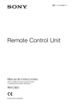
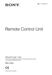
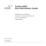
A-AVM-100-11 (1) CCD Black-and-White Video Camera Module Technical Manual XC-EU50/EU50CE 2001 Sony Corporation Table of Contents Overview Main Features ............................................................ System Components ................................................. Connection Diagram ................................................. Location of Parts and Operation .............................. 3 4 4 5 Front/Top/Bottom ........................................................ 5 Rear Panel ................................................................. 6 Mode Setting Specifications of the Input/Output ........................... 8 Input Phase Specifications of the External HD/VD .... 8 Specifications of the WEN Output .............................. 8 Specifications of the Trigger Pulse ............................. 8 Normal Shutter .......................................................... 9 Setting of the Normal Shutter ..................................... 9 External Trigger Shutter ............................................ 9 Setting of the External Trigger Shutter ....................... 9 Restart/Reset ........................................................... 11 To set Restart/Reset mode ....................................... 11 Timing Charts .......................................................... 13 When set to Mode 1 ................................................. 13 When set to Mode 2 ................................................. 19 Appendix Specifications .......................................................... 21 Dimensions .............................................................. 22 XC-EU50/EU50CE ................................................... 22 Spectral Sensitivity Characteristics (Typical Value) ....................................................... 22 Recommended light source ................................... 22 CCD Output Waveform Timing Chart ..................... 23 XC-EU50 .................................................................. 23 XC-EU50CE ............................................................. 25 2 Overview Overview The XC-EU50/EU50CE is a monochrome video camera module with a 1/2 type CCD for industrial use. With its sensitivity around the near ultraviolet range (around 360 nm), utilized the feature of the shorter wavelength range characteristics and very detailed data can be detected. Small scratches, dust or blemishes hardly visible to the naked eye can be captured as a clear image by combining the camera with a light source that has a wavelength of about 360 nm. This model inherited compact size, rear panel mode switches from the XC-E series and is ideal for use in industrial applications. Main Features External trigger shutter function (EIA: 1/4 to 1/10,000 seconds, CCIR: 1/4 to 1/8,000 seconds) You can obtain a freeze picture by inputting an external trigger. This function is useful for shooting a fast-moving object clearly. Restart/Reset function Inputting external HD and VD signals (2 VD or more) continuously can catch one image at an arbitrary point in time and control the stored CCD. This function is used for long exposures and with strobe for frame image output. Body fixing Various mode settings Rear panel switches allow the following mode settings. • Gain: Auto/Manual • γ compensation • Synchronized input/output • Potential accumulation: FRAME/FIELD • 75 Ω termination • Shutter: Normal/Trigger shutter External synchronization Mounting screw holes are provided in the reference plane on the lower surface of the body, allowing mounting with the absolute minimum deviation of the optical axis. The connector complies with the new EIAJ 12-pin pin assignment The new pin arrangement allows the connector to accept a trigger pulse and a WEN signal. The camera module automatically determines whether to operate in interlace or non-interlace mode from the HD (horizontal drive) and VD (vertical drive) signals input for external synchronization. Internal sync signal output You can output the HD and VD signals from the 12pin connector by changing the setting of the rear panel switch. 3 Overview System Components The XC-EU50/EU50CE Video Camera Module system comprises the following components. Video camera module XC-EU50/EU50CE Camera cables CCXC-12P02N(2 m) CCXC-12P05N(5 m) CCXC-12P10N(10 m) CCXC-12P25N(25 m) C-mount lens VCL-50Y-M Tripod adaptor VCT-333I (Insulated type) Camera adaptor DC-700/700CE Close-up ring kit LO-77ERK Connection Diagram XC-EU50/EU50CE C-mount lens VCL-50Y-M Tripod adaptor VCT-333I Camera cables CCXC-12P02N CCXC-12P05N CCXC-12P10N CCXC-12P25N AC VIDEO OUT HD/VD WEN TRIG Camera adaptor DC-700/700CE (Conforms to new EIAJ and uses 12-pin assignment) Close-up ring kit LO-77ERK 4 Overview Location of Parts and Operation Front/Top/Bottom 1 Lens mount (C-mount) 2 Reference holes 3 Reference holes/Tripod screw holes 1 Lens mount (C-mount) Attach the VCL-50Y-M C-mount lens or other optical equipment. 2 Reference holes (Top) These precision screw holes are for locking the camera module. Locking the camera module into these holes secures the optical axis alignment. 3 Reference holes/Tripod screw holes (bottom) These precision screw holes are for locking the camera module. Locking the camera module using these holes secures the optical axis alignment. You can install the camera on a tripod. To install on a tripod, you will need to install the VCT-333I tripod adaptor using the reference holes on the bottom of the camera. 5 Overview Rear Panel 1 VIDEO OUT/DC IN/SYNC (video output/DC power input/sync signal I/O) connector (12-pin) 2 Shutter speed/Mode setting DIP switch 5 75Ω termination switch 3 Manual GAIN (M GAIN) control knob 4 HD/VD signal input/output switch Note When you do switch settings, make sure the unit is off. 1 VIDEO OUT/DC IN/SYNC (video output/DC power input/sync signal I/O) connector (12-pin) Connect a CCXC-12P05N camera cable to this connector for the +12V DC power supply and the video signal output from the camera module. When a sync signal generator is connected to this connector, the camera module is synchronized with the external sync signals (HD/VD signals). 2 Shutter speed/Mode setting DIP switch Shutter speed (bits 1–4): Set an appropriate shutter speed. (Factory setting: OFF) Potential accumulation mode (bit 5): (Factory setting: FRAME) Restart reset/External trigger shutter mode switch (bits 6–8): (Factory setting: Normal) γ compensation ON/OFF switch (bit 9): Turn on this switch to enable the γ compensation. (Factory setting: OFF) GAIN switch (bit 0): This switch selects MGC (manual adjustment) or AGC (automatic adjustment). (Factory setting: MGC) 3 Manual GAIN (M GAIN) control knob If you have selected MGC with the GAIN switch (DIP switch 2), this knob adjusts the gain. (Factory setting: twelve o’clock position) Note If you have selected FRAME using the Potential accumulation mode (DIP switch 2), set this knob to MAX. (This is due to requirement CCD.) 4 HD/VD signal input/output switch Set the switch to INT to output HD/VD signals from the camera module. Set the switch to EXT to input HD/VD signals from an external unit. (Factory setting: EXT) 5 75Ω termination switch Turn this to OFF when not terminated. (Factory setting: ON) 6 Overview VIDEO OUT/DC IN/SYNC connector pin assignment Rear panel Pin No. Camera sync output External Sync (HD/VD) Restart/Reset External trigger shutter 1 Ground Ground Ground Ground 2 +12 V DC +12 V DC +12 V DC +12 V DC 3 Video output (Ground) Video output (Ground) Video output (Ground) Video output (Ground) 4 Video output (Signal) Video output (Signal) Video output (Signal) Video output (Signal) 5 HD output (Ground) HD input (Ground) HD input (Ground) HD input (Ground) 6 HD output (Signal) HD input (Signal) HD input (Signal) HD input (Signal) 7 VD output (Signal) VD input (Signal) Reset (Signal) VD input (Signal) 8 — — — 9 — — — 10 — — — WEN output (Signal) — Trigger pulse input (Signal) 11 12 — VD output (Ground) — VD input (Ground) Reset (Ground) — — VD input (Ground) Factory setting mode of rear panel 1 4 Number 3 2 Switch name Shutter speed (bits 1–4) 1 Shutter speed/ Mode setting DIP switch Factory-setting mode OFF Potential accumulation mode (bit 5) FRAME Restart reset/External trigger shutter mode switch (bits 6–8) Normal γ compensation ON/OFF switch (bit 9) GAIN switch (bit 0) OFF MGC 2 Manual GAIN (M GAIN) control knob 3 HD/VD signal input/output switch twelve o’clock position* EXT 4 75 Ω termination switch ON * When the GAIN switch is set to “MGC” (Manual), you can change the gain level in a range from 0 to 18 dB. 7 Mode Setting Mode Setting Specifications of the Input/Output Input Phase Specifications of the External HD/VD 5 External VD EVEN, Non Interlace 100 Specifications of the Trigger Pulse 4 to 5.0 V 200 2 µsec to 1/4 sec 200 0 to 1.0 V ODD External HD 455 (454) 455 (454) ( ): CCIR Unit: Clock 1Clk=69.84 nsec (EIA) 70.48 nsec (CCIR) Make sure that the external HD/VD phases against the standard central phase are as shown in the figure above. Invalid signal input may cause an error in the internal reset. When you restart/reset the camera or operate the camera by inputting an external trigger shutter pulse, the Vsync signal for the image is output 1 H later from the external VD. Normal: HD/VD continuous (EIA/CCIR frequencies: Maintained. Timing: See the above figure.) Restart/Reset and /External trigger shutter HD continuous/VD (Reset): Any timing if the phase with HD is within the above range. Specifications of the WEN Output 4.5 V 250 H(EIA) 293 H(CCIR) 0V The amplitude level is the typical value when terminated with 10 kΩ. • Input impedance; 10 kΩ or more. • The voltage and pulse width used are measured at pin 11 of a 12-pin multi-connector on the rear panel. • If you set the trigger pulse with the DIP switches, use the 100 µs to 1/4 sec pulse width. Setting the external shutter speed with the trigger pulse width Set all DIP switches (1 to 4 on the rear panel) to 0. You can obtain an arbitrary shutter speed by setting the trigger pulse width to the range of 2 µsec to 250 msec. Mode 1 (Non-reset mode) Mode 2 (Reset mode) Exposure time = Trigger pulse width + 97 µsec (EIA) Trigger pulse width + 120 µsec (CCIR) Notes • The DIP switch 5 position is optional. (The field setting is recommended.) The field setting can obtain a sensitivity that is twice that of the frame setting. • If you input a new trigger pulse before the video signal output for the previous trigger pulse is output completely, an incorrect video signal will be output. 8 Mode Setting Normal Shutter External Trigger Shutter This mode provides continuous video output with the electronic shutter selected by switches to capture a high-speed moving object clearly. By inputting an external trigger pulse, the camera is able to capture fast-moving objects clearly. Set DIP switches 6, 7, and 8 on the rear panel to Mode 1 or Mode 2 (See the table below). When you set the trigger pulse width to 1/3 of a second or more, the output signal changes to the normal VIDEO signal. Setting of the Normal Shutter Using the DIP switches on the rear panel Shutter OFF 1/125 1/250 1/4000 1/10000 (EIA) 1/8000 (CCIR) 1/500 1/1000 There are two modes for timing in which a video signal is obtained. • Mode 1 (Non-reset mode) In this mode, a video signal synchronized with a VD signal is output after a trigger pulse is input. – A video signal is synchronized with the external VD signal when an external HD/VD signal is input. – A video signal is synchronized with an internal VD signal when no external HD/VD signal is input. • Mode 2 (Reset mode) In this mode, an internal VD is reset, then an internal video signal is output after trigger pulse input after a certain period of time. For details of each timing chart, see pages 13 to 20. 1/2000 Flickerless* (EIA: 1/100 CCIR: 1/120) Setting of the External Trigger Shutter You can set the shutter speed with the DIP switches or using the trigger pulse width. To set the shutter speed with the trigger pulse width, see page 8. Using the DIP switches on the rear panel Mode 1 (Non-reset mode) (Unit: second) * If you set the mode to flickerless, the positions of DIP switches 1 to 3 are optional. 1/100 (EIA)* 1/120 (CCIR)* 1/125 1/250 1/500 1/4000 1/10000 (EIA) 1/8000 (CCIR) Notes • The positions of DIP switches 6 and 7 are optional. • The DIP switch 5 position is optional. (The field setting is recommended.) The field setting can obtain a sensitivity that is twice that of the frame setting. 1/1000 1/2000 (Unit: second) 9 Mode Setting Mode 2 (Reset mode) 1/100 (EIA)* 1/120 (CCIR)* 1/125 1/250 1/500 1/1000 1/2000 1/4000 1/10000 (EIA) 1/8000 (CCIR) (Unit: second) * If 1/100 (EIA) or 1/120 (CCIR) has been set, the positions of DIP switches 1 to 3 are optional. Note The positions of DIP switches 5, 9 and 0 are optional. 10 Mode Setting Restart/Reset To set Restart/Reset mode The information on one screen can be extracted at any time by externally inputting a restart/reset signal (HD/ VD). To enter this mode, set DIP switches 6, 7, and 8 on the rear panel of the camera as shown in the figure below. The setting is especially effective for the operation explained below. Long exposure The Restart/Reset function extends the CCD accumulation time, resulting in a highly sensitive image. This function is effective when you cannot gain satisfactory sensitivity under normal operating conditions, or when you want to observe a moving object. Extend the VD interval (T) period between external VD pulses. Note Some white spots may appear after a long exposure. Sample input timing chart 1 EXT HD Continuous signal: 15.734 kHz (XC-EU50) Allowable frequency value ±1%, 15.625 kHz (XC-EU50CE) Allowable frequency value ±1% EXT VD VD interval (T): 262.5 H or more (XC-EU50) and less than 1 second (Recommended), 312.5 H or more (XC-EU50CE) and less than 1 second (Recommended) Four or more VD pulses are required. T T T Exposure time for the Odd field Exposure time for the Even field Frame Accumulation (Factory setting) Video output Odd image Invalid image Even image Valid frame image Odd and even fields are determined by the phase of the EXT HD/VD signal input from the outside. 11 Mode Setting Sample input timing chart 2 EXT HD Continuous signal: 15.734 kHz (XC-EU50) Allowable frequency value ±1%, 15.625 kHz (XC-EU50CE) Allowable frequency value ±1% EXT VD VD interval (T): 262.5 H or more (XC-EU50) and less than 1 second (Recommended), 312.5 H or more (XC-EU50CE) and less than 1 second (Recommended) Four or more VD pulses are required. T 1/60 second 1/60 second Exposure time for the Odd field Exposure time for the Even field Frame Accumulation (Factory setting) Video output Odd image Invalid image Even image Valid frame image Odd and even fields are determined by the phase of the EXT HD/VD signal input from the outside. Frame image output with a strobe light The factory setting for this camera is Frame Accumulation. The images obtained when the normal continuous shutter or trigger shutter is used are field images (vertical resolution: 243 lines). Using a strobe light and Restart/Reset mode, you can obtain bright frame images by synchronizing any strobe light. (Vertical resolution: 485 lines). Sample input timing chart EXT HD Continuous signal: 15.734 kHz (XC-EU50) Allowable frequency value ±1%, 15.625 kHz (XC-EU50CE) Allowable frequency value ±1% EXT VD VD: 1/60 sec (XC-EU50), 1/50 sec (XC-EU50CE) Four or more VD pulses are required. Strobe light Exposure time for the Odd field Exposure time for the Even field Frame Accumulation (Factory setting) Video output Odd image Invalid image Even image Valid frame image Odd and even fields are determined by the phase of the EXT HD/VD signal input from the outside. Avoid lighting the scene during the light-emitting inhibit zone defined below. (The field is transfered to the storage area of the CCD, so it can be read out.) Note For best performance, it is recommended that you not flash between VD and VD + 10 H (XC-EU50)/16 H (XC-EU50CE). 12 Mode Setting Timing Charts When set to Mode 1 For setting the shutter speed using the trigger pulse width HD/VD input ◆ Continuous VD input Normal operation*3 External trigger shutter operation 1 Mode transition state External input External trigger inhibition area shutter operation (50 ms) 3 2 Trigger*1 Trigger pulse width* 3 Exposure time (Te)*2 Exposure time (Te)*2 Exposure time (Te)*2 External HD*1 External VD*1 (Continuous VD) EXT-VD T: T=under 10 µs*4 T: T=under 10 µs*4 10 µs or more Video out 3 2 1 *5 WEN 250 H (EIA) 293 H (CCIR) TRG EXT-VD EXT-VD 65 µs 10 µs *1 This is a signal input from outside. Make sure to input both HD and VD signals. *2 Exposure time (Te) Te = Trigger pulse width + 97 µsec (EIA) Te = Trigger pulse width + 120 µsec (CCIR) (The effective trigger pulse width for the external trigger shutter operation is between 2 µs and 1/4 s.) *3 The normal operation state is chosen when the trigger pulse width is 1/3 s or more. The trigger falling edge restores the external trigger shutter operation. In this case, the area between the falling edge of a trigger pulse and the subsequent 50 ms period is an external trigger input inhibition area. There is no guarantee of operation for any trigger input selected in this period. *4 If there is a falling edge on the external VD within a period of –65 to +10 µs from the falling trigger edge (1 and 2 in the figure), it is not defined whether the image is output for the external VD falling edge or the image is output for the next external VD falling edge. (1 in the figure shows that the image is output for the next external VD. 2 shows the image for the external VD.) In this case, see WEN since output of the image and WEN make up a pair. In any other cases, the image is output for the external VD falling edge after the trigger falling edge (3 in the figure). *5 When the external trigger shutter mode changes to the normal operation mode, one WEN signal is output. Note An image is not output correctly when the next trigger is input before the image for the previous trigger is output. 13 Mode Setting For setting the shutter speed using the trigger pulse width HD/VD input ◆ Continuous HD input/Single VD input External trigger shutter operation Normal operation*3 1 Mode transition state External input inhibition area External trigger shutter operation (50 ms) 2 Trigger*1 Trigger pulse width* 3 Exposure time (Te)*2 Exposure time (Te)*2 External HD*1 External VD*1 (Single VD) T: T=10 µs to 65 ms*4 min 10 µs Video out 2 1 5 * WEN 250 H (EIA) 293 H (CCIR) *1 This is a signal input from outside. Make sure to input both HD and VD signals in this case. Input the signal so that the VD phase aligns with the HD falling edge. *2 Exposure time (Te) Te = Trigger pulse width + 97 µsec (EIA) Te = Trigger pulse width + 120 µsec (CCIR) (The effective trigger pulse width for the external trigger shutter operation is between 2 µs and 1/4 s.) *3 The normal operation state is chosen when the trigger pulse width is 1/3 s or more. (By entering a continuous VD in this section, an image is output.) The trigger falling edge restores the external trigger shutter operation. In this case, the area between the falling edge of a trigger pulse and the subsequent 50 ms period is an external trigger input inhibition area. There is no guarantee of operation for any trigger input selected in this period. 250 H (EIA) 293 H (CCIR) 250 H (EIA) 293 H (CCIR) *4 Input the external VD within the period of 10 µs to 65 ms after the trigger falling edge (1 and 2 in the figure). There is no guarantee of operation when any other input is selected. If an invalid signal is input, the input is changed to a valid signal and, after several V signals, normal operation will resume. *5 When the external trigger shutter mode changes to the normal operation mode, one WEN signal is output. Note Make sure that the trigger signal and the VD signal make up a pair. An image is not output correctly when the next trigger is input before the image for the previous trigger is output. 14 Mode Setting For setting the shutter speed using the trigger pulse width No HD/VD input (Internal synchronization) External trigger shutter operation Normal operation*3 2 1 Mode transition state External input inhibition area External trigger (50 ms) shutter operation 3 Trigger*1 Trigger pulse width* 3 4 Internal HD* Exposure time (Te)*2 Exposure time (Te)*2 Exposure time (Te)*2 T: T=10 µs or more*5 T: T=under 10 µs*5 Video out 1 3 2 *6 WEN 250 H (EIA) 293 H (CCIR) *1 This is a signal input from outside. *2 Exposure time (Te) Te = Trigger pulse width + 97 µsec (EIA) Te = Trigger pulse width + 120 µsec (CCIR) (The effective trigger pulse width for the external trigger shutter operation is between 2 µs and 1/4 s.) *3 The normal operation state is chosen when the trigger pulse width is 1/3 s or more. The trigger falling edge restores the external trigger shutter operation. In this case, the area between the falling edge of a trigger pulse and the subsequent 50 ms period is an external trigger input inhibition area. There is no guarantee of operation for any triggers input in this period. *4 The internal VD signals are output as long as there is no external input and the HD/VD signal I/O switch on the rear panel is set to INT. *5 In the external trigger operation, the image is output for the internal VD falling edge after the trigger falling edge (1 and 2 in the figure). If the period from the trigger falling edge to the internal VD falling edge (T in the figure) is under 10 µs, there may be a delay of 1 VD in the output. (3 in the figure shows that the image is output for the next internal VD). In this case, see WEN since the image and WEN make up a pair. (The internal VD falling edge and the beginning of the equivalent pause in the V period of the SYNC have the same phase.) *6 When the external trigger shutter mode changes to the normal operation mode, one WEN signal is output. Note An image is not output correctly when the next trigger is input before the image for the previous trigger is output. 15 Mode Setting For setting the shutter speed using the DIP switches HD/VD input ◆ Continuous VD input Normal operation*3 External trigger shutter operation 1 Trigger*1 2 100 µs to 250 ms Exposure time (Te)*2 3 Trigger pulse width*3 Exposure time (Te)*2 External HD*1 External VD*1 (Continuous VD) T: T=under 10 ms*4 Mode transition state External input External trigger inhibition area shutter operation (50 ms) Exposure time (Te)*2 T: T=10 ms or more*4 T: T=10 ms or more*4 Video out 1 3 2 WEN 250 H (EIA) 293 H (CCIR) 250 H (EIA) 293 H (CCIR) *1 This is a signal input from outside. The continuous VD frequency is one field. Make sure you input HD and VD at the same time. *2 The exposure time (Te) is determined by the setting of the DIP switches. For details, see Page 9. *3 The normal operation state is chosen when the trigger pulse width is 1/3 s or more. The trigger falling edge restores the external trigger shutter operation. In this case, the area between the falling edge of a trigger pulse and the subsequent 50 ms period is an external trigger input inhibition area. There is no guarantee of operation for any triggers input in this period. *4 An image is output when an external VD signal falls 10 ms or more after a trigger pulse rises (2 and 3 in the figure). If the period from the trigger rising edge to the external VD falling edge (T in the figure) is under 10 ms, there may be a delay of 1 VD in the output. (1 in the figure shows that the image is output for the next external VD). In this case, see WEN since the image and WEN make up a pair. Note An image is not output correctly when the next trigger is input before the image for the previous trigger is output. 16 Mode Setting For setting the shutter speed using the DIP switches HD/VD input ◆ Continuous HD input/Single VD input External trigger shutter operation Normal operation*3 2 1 Trigger*1 Mode transition state External input External trigger inhibition area shutter operation (50 ms) 100 µs to 250 ms Trigger pulse width*3 Exposure time (Te)*2 Exposure time (Te)*2 External HD*1 External VD*1 (Single VD) min.10 ms T: T=10 ms to 75 ms*4 Video out 2 1 WEN 250 H (EIA) 293 H (CCIR) 250 H (EIA) 293 H (CCIR) *1 This is a signal input from outside. Make sure to input both HD and VD signals in this case. Input the signal so that the VD phase aligns with the HD falling edge. *2 The exposure time (Te) is determined by the setting of the DIP switches. *4 Input the external VD within the period of 10 ms to 75 ms after the trigger rising edge (1 and 2 in the figure). There is no guarantee of operation when any other input is selected. If an invalid signal is input, the input is changed to a valid signal, and after several V signals, normal operation will resume. For details, see Page 9. Note *3 The normal operation state is chosen when the trigger pulse width is 1/3 s or more. (By entering a continuous VD in this section, an image is output.) The trigger falling edge restores the external trigger shutter operation. In this case, the area between the falling edge of a trigger pulse and the subsequent 50 ms period is an external trigger input inhibition area. There is no guarantee of operation for any triggers input in this period. Make sure that the trigger signal and the VD signal make up a pair. An image is not output correctly when the next trigger is input before the image for the previous trigger is output. 17 Mode Setting For setting the shutter speed using the DIP switches No HD/VD input (Internal synchronization) Normal operation*3 External trigger shutter operation 1 Trigger*1 100 µs to 250 ms Exposure time (Te)*2 Mode transition state External input inhibition area (50 ms) External trigger shutter operation 3 2 3 Trigger pulse width* Exposure time (Te)*2 Exposure time (Te)*2 Internal VD*4 T: T=10 ms or more*5 T: T=10 ms or more*5 T: T=under 10 ms*5 Video out 1 3 2 WEN 250 H (EIA) 293 H (CCIR) 250 H (EIA) 293 H (CCIR) *1 This is a signal input from outside. *2 The exposure time (Te) is determined by the setting of the DIP switches. For details, see Page 9. *3 The normal operation state is chosen when the trigger pulse width is 1/3 s or more. The trigger falling edge restores the external trigger shutter operation. In this case, the area between the falling edge of a trigger pulse and the subsequent 50 ms period is an external trigger input inhibition area. There is no guarantee of operation for any triggers input in this period. *4 The internal VD signals are output as long as there is no external input and the HD/VD signal input/output switch on the rear panel is set to INT. *5 An image is output when an internal VD signal falls 10 ms or more after a trigger pulse rises (2 and 3 in the figure). If the period from the trigger rising edge to the internal VD falling edge (T in the figure) is under 10 ms, it is not defined whether the image is output for the internal VD falling edge or the image is output for the next internal VD falling edge. (1 in the figure shows that the image is output for the next internal VD). In this case, see WEN since the image and WEN make up a pair. (The internal VD falling edge and the beginning of the equivalent pause in the V period of the SYNC have the same phase.) Note An image is not output correctly when the next trigger is input before the image for the previous trigger is output. 18 Mode Setting When set to Mode 2 For setting the shutter speed using the trigger pulse width Normal operation*3 External trigger shutter operation Trigger*1 Exposure time (Te)*2 Mode transition state External input inhibition area External trigger (50 ms) shutter operation Trigger pulse width*3 Exposure time (Te)*2 Video out 1 H to 2 H*4 *5 1 H to 2 H*4 WEN 250 H (EIA) 293 H (CCIR) *1 This is a signal input from outside. The trigger input frequency must be [Trigger pulse width + 1 field + 2 H frequency] or more. The operation is not guaranteed for shorter frequencies. If invalid data is input, normal operation is resumed several Vs after entering the correct data. 250 H (EIA) 293 H (CCIR) 250 H (EIA) 293 H (CCIR) *4 A VD signal is generated after 1 H to 2 H from the trigger falling edge, then the image is output synchronized with the VD generation. *5 When the external trigger shutter mode changes to the normal operation mode, one WEN signal is output. *2 Exposure time (Te) Te = Trigger pulse width + 97 µsec (EIA) Te = Trigger pulse width + 120 µsec (CCIR) (The effective trigger pulse width for the external trigger shutter operation is between 2 µs and 1/4 s.) *3 The normal operation state is chosen when the trigger pulse width is 1/3 s or more. The trigger falling edge restores the external trigger shutter operation. In this case, the area between the falling edge of a trigger pulse and the subsequent 50 ms period is an external trigger input inhibition area. There is no guarantee of operation for any triggers input in this period. 19 Mode Setting For setting the shutter speed using the DIP switches External trigger shutter operation Trigger*1 100 µs to 250 ms Exposure time (Te)*2 Normal operation*3 Mode transition state External input inhibition area External trigger (50 ms) shutter operation Trigger pulse width*3 Exposure time (Te)*2 Video out WEN T*4 T*4 250 H (EIA) 293 H (CCIR) *1 This is a signal input from outside. The trigger input frequency must be [Shutter speed (DIP switches) + 1 field + 2 H frequency] or more. If invalid data is input, normal operation is resumed several Vs after entering the correct data. *4 The image is output at the shortest timing from the trigger rising edge according to the DIP switch setting. *2 The exposure time (Te) is determined by the setting of the DIP switches. For details, see Page 10. *3 The normal operation state is chosen when the trigger pulse width is 1/3 s or more. The trigger falling edge restores the external trigger shutter operation. In this case, the area between the falling edge of a trigger pulse and the subsequent 50 ms period is an external trigger input inhibition area. There is no guarantee of operation for any triggers input in this period. 20 Appendix Appendix Specifications Image pickup device 1/2type interline transfer CCD Number of effective pixels XC-EU50: 768 (H) × 494 (V) XC-EU50CE: 752 (H) × 582 (V) Cell size XC-EU50: 8.4 (H) × 9.8 (V) µm XC-EU50CE: 8.6 (H) × 8.3 (V) µm Chip size XC-EU50: 7.95 (H) × 6.45 (V) mm XC-EU50CE: 7.95 (H) × 6.45 (V) mm CCD horizontal driving frequency XC-EU50: 14.318 MHz XC-EU50CE: 14.187 MHz CCD vertical driving frequency XC-EU50: 15.734 kHz ± 1% XC-EU50CE: 15.625 kHz ± 1% Signal system XC-EU50: EIA XC-EU50CE: CCIR Lens mount C-mount Flange back 17.526 mm (23/32 inches) (light wavelength: 360 nm) Synchronization system Internal/External (Selected automatically) External synchronization input/output HD/VD (2 to 5 Vp-p) * Automatically selected according to the existence of an input signal when the selection switch on the rear panel has been set to EXT. Allowable frequency deviation of external synchronization ±1% (in horizontal synchronous frequency) Jitter Within ±50 nsec Scanning system XC-EU50: 525 lines XC-EU50CE: 625 lines 2:1 interlace/noninterlace (automatically switched according to input signal) Horizontal resolution XC-EU50: 570 TV lines XC-EU50CE: 560 TV lines S/N ratio 60 dB GAIN AGC/Manual (Can be selected using the DIP switch on the rear panel) Gamma compensation ON/OFF (Can be selected using the DIP switch on the rear panel) Electronic shutter XC-EU50: 1/100 to 1/10,000 second XC-EU50CE: 1/120 to 1/10,000 second External trigger shutter XC-EU50: 1/4 to 1/10,000 second XC-EU50CE: 1/4 to 1/8,000 second * Can be changed using the trigger pulse width or set using the DIP switches on the rear panel. Power requirement DC +12 V (+9.0 V to 16 V) Power consumption 1.6 W Operating temperature –5 °C to +45 °C (23 °F to 113 °F) Storage temperature –20 °C to +60 °C (–4 °F to 140 °F) Performance assurance temperature 0 °C to +30 °C (32 °F to 86 °F) Operating humidity 20 to 80% (Non-condensing) Storage humidity 20 to 95% (Non-condensing) Vibration resistance 10 G (For 20 minutes in the X,Y and Z directions at 20 to 200 Hz) Shock resistance 70 G Outside dimensions 29 (W) × 29 (H) × 32 (D) mm (1 3/16 (W) × 1 3/16 (H) × 1 5/16 (D) inches) 21 Appendix Weight Standards 50 g (2 oz) UL1492, FCC Class A Digital Device, CE (EN50081-2 +EN50082-2), AS3548 (Class A) Restart/Reset function Frame or field accumulation can be selected. New EIAJ compliance 12-pin connector pin assignment External trigger shutter Lens mount cap (1) Operating Instructions (1) Other Accessories Dimensions Relative 1.0 sensitivity 0.9 0.8 0.7 0.6 0.5 0.4 0.3 0.2 0.1 0.0 300 320 340 360 380 400 420 Wavelength (nm) Note XC-EU50/EU50CE Top Spectral Sensitivity Characteristics (Typical Value) The lens characteristics and light source characteristics are excluded. 2-M2 deep 2.5 29 12 Recommended light source Side C 5 0. 0. C 5 4.5 Use a light source that has a wavelength of about 360 nm, such as black light. For more details, contact your nearest Sony dealer. 29 XC-EU50 6.5 10 32 5.5 1.7 8.0 5 0. C 29 12 Bottom 4-M2 deep 2.5 6.5 22 29 Front 29 Unit: mm (inches) 22 Appendix CCD Output Waveform Timing Chart XC-EU50 Horizontal Output Waveform Timing Chart HD 91 (6.36 µs) 40 77 22 3 15 752 CCD output signal Effective total pixels 768 69.8 ns Camera video output signal (Typical value) Dummy bits Optical black portion Horizontal transfer stop period Optical black portion Horizontal blanking period (11.0 µs) 21 HSYNC (1.47 µs) 70 (4.89 µs) 67 (4.68 µs) Output video period 752 (52.5 µs) One horizontal scanning period (1 H) 910 (63.56 µs) * Values without units indicate the clock counts. 23 Appendix Vertical Output Waveform Timing Chart (2:1 interlaced frame accumulation) Odd field (262.5 H) Even field (262.5 H) VD 9H 253.5 H 9H 1 8 6 4 242.5 2 4 6 8 2 8 Empty transfer Camera video output signal 494 492 490 493 491 489 494 1 3 5 7 9 CCD output signal 253.5 H 6 3.5 242.5 Empty transfer Optical black portion Optical black portion Vertical blanking period (20 H) Vertical blanking period (20 H) * The transfer stop period is included in the dummy bits. Vertical Output Waveform Timing Chart (2:1 interlaced field accumulation) Odd field (262.5 H) Even field (262.5 H) VD 1 8 6 4 Empty transfer Optical black portion Vertical blanking period (20 H) 253.5 H 242.5 7+8 5+6 3+4 1+2 8+9 6+7 4+5 2+3 1 CCD output signal Camera video output signal 9H 493+494 491+492 489+490 253.5 H 494 492+493 490+491 488+489 9H 1 8 6 3.5 242.5 Empty transfer Optical black portion Vertical blanking period (20 H) * The transfer stop period is included in the dummy bits. 24 Appendix XC-EU50CE Horizontal Output Waveform Timing Chart HD 98 (6.91 µs) 40 91 22 3 15 736 CCD output signal Effective total pixels 752 70.5 ns Dummy Optical black bits portion Horizontal transfer stop period Optical black portion Horizontal blanking period (12.1 µs) Output video period Camera video output signal (Typical value) 21 HSYNC (1.48 µs) 70 (4.93 µs) 81 (5.71 µs) 736 (51.9 µs) One horizontal scanning period (1 H) 908 (64.0 µs) * Values without units indicate the clock counts. 25 Appendix Vertical Output Waveform Timing Chart (2:1 interlaced frame accumulation) Odd field (312.5 H) Even field (312.5 H) VD 7.5 H 305 H 1 14 6 3.5 287.5 2 4 6 8 2 Empty transfer Camera video output signal 582 580 581 579 1 3 5 7 9 CCD output signal 305 H 7.5 H 14 6 287.5 3 Empty transfer Optical black portion Optical black portion Vertical blanking period (25 H) Vertical blanking period (25 H) * The transfer stop period is included in the dummy bits. Vertical Output Waveform Timing Chart (2:1 interlaced field accumulation) Odd field (312.5 H) Even field (312.5 H) VD 1 14 6 3.5 Empty transfer Optical black portion Vertical blanking period (25 H) 305 H 287.5 7+8 5+6 3+4 1+2 8+9 6+7 4+5 2+3 1 CCD output signal Camera video output signal 7.5 H 581+582 579+580 305 H 582 580+581 578+579 7.5 H 1 14 6 3 287.5 Empty transfer Optical black portion Vertical blanking period (25 H) * The transfer stop period is included in the dummy bits. 26 Appendix Sony reserves the right to change specifications of the products and discontinue products without notice. Technical information contained herein is for reference only and does not convey any license by any implication or otherwise under any intellectual property right or other right of Sony or third parties. Sony cannot assume responsibility for any right infringements arising out of the use of this information. 27