1
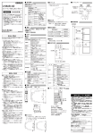
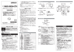
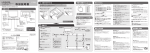
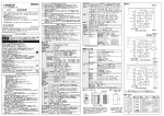
31
警告
人体への安全を確保するための安全機器あるいは安全システム
の一部としてシングルビームセーフティセンサ形E3ZSを使用す
る場合には、必ずセーフティコントローラ形F3SXシリーズに接続
してご使用ください。
2-M3
ビニル絶縁丸形コード
φ4,投光器:3芯,受光器:4芯
(導体断面積:0.2mm /絶縁体径 φ1.1mm)
標準長さ2m
・E 3 Z SをF 3 S Xに接 続して使 用する場 合は、安 全カテゴリ2
(EN954-1)までの要件を満たします。
警告
● 適用範囲
以上の内容は、
日本国内での取引および使用を前提としております。
日本国外での取引および使用に関しては、
当社営業担当者までご
相談ください。
使用周囲照度
周囲湿度
動作時:35∼85%RH、保存時:35∼95%RH
(ただし、氷結、結露なきこと。)
絶縁抵抗
20MΩ以上(DC 500Vメガにて)
AC 1,000V、50/60Hz、1min.
耐電圧
耐久
動作限界
耐久
動作限界
耐振動
耐衝撃
10∼55Hz 複振幅1.5mm X,Y,Z各方向2h
10∼55Hz 複振幅0.7mm X,Y,Z各方向50min.
500m/s2(約50G) X,Y,Z各方向3回
100m/s2(約10G) X,Y,Z各方向1,000回
IEC規格 IP67
赤色発光ダイオード
保護構造
光源
保護回路
質量(梱包状態)
電源・出力逆接続保護、
負荷短絡保護
約120g
(1セット)
2. セーフティコントローラ形F3SXと組合せて使用する場合は、B1モ
ジュールに正しく接続してご使用ください。
4. センサに貼り付けてありますラベル(黄色)は剥がさないでくださ
い。仕様を満たさなくなることがあります。
5. 接続コードはピンと張らずに余裕を持たせ、作業者や物の移動
を妨げることが無いように配線されていることを確認してください。
E3ZSを単体で使用する場合
EN954-1(カテゴリ1)
IEC60947-5-3
(PDF-D)
UL508
E3ZSをF3SXに接続して使用する場合
IEC61496-1 Type2 ESPE
IEC61496-2 Type2 AOPD
EN954-1(カテゴリ2)
UL508
UL61496-1 Type2 ESPE
UL61496-2 Type2 AOPD
取扱説明書
適用規格
付属品
動作位置
[mm]
2
4
6
8
10
PNP出力 出力モード:入光時ON
(Light ON)
■光沢面の影響
D
5°
5°
L
投光器と受光器間の距離
(検出距離L) 設置許容距離D
0.27 m 以上
0.2∼3 mのとき
■相互干渉の影響
シングルビーム セーフティセンサ同士の相互干渉を避けるため、下記の項
目を考慮して設置してください。
・投光器と受光器を交互に位置を変えて設置する(下図参照)。
投光器
受光器
受光器
投光器
投光器
受光器
・遮光板を使用して分ける。
・充分な間隔を空けて設置する。
※複数のシングルビーム セーフティセンサを使用する際は、
相互干渉が起きてないことを必ず確かめてください。
■アクセサリ(別売り)
● 取付金具
(形E39-L104)
R2
0
14゚
3.4
出力/入力回路図
7. 廃棄するときは、産業廃棄物として処理してください。
6
4.5
29
使用上の注意
1. 次のような場所には設置しないでください。
・直射日光など、強い外乱光があたる場所
・湿度が高く、結露する恐れがある場所
・腐食性ガス、
引火性ガス、
爆発性ガスのある場所
・品質低下を招く恐れのある煙や微粒子のある場所
・仕様で定められる以上の振動や衝撃が、本体に伝わる場所
・水、油、薬品のかかる場所
2. E3ZSを水中で使用しないでください。
組み合わせる直流電源には以下のUL認証品をご使用ください。
(1)UL508に従う制限電圧電流回路
次の条件を満足する絶縁トランスの2次側巻線を電源とする回路
・最大電圧(無負荷時):30Vrms(42.4Vピーク)以下および
・最大電流
:①8A以下(短絡時を含む)または
②下表の定格を持つ回路保護機器
(ヒューズ等)で制限されている場合
無負荷電圧
(Vピーク)
最大電流定格
(A)
0∼20
5.0
20を超え30まで
100
ピーク電圧値
(2)UL1310に従うクラス2電源ユニット
(3)UL1585に従うクラス2トランスを電源とする最大電圧30Vrms
(42.4Vピーク)以下の回路(クラス2回路)
7.本製品はクラスA機器です。家庭用環境において、本製品は電
波障害を起こすことがあります。
この場合は、責任者が十分な対
策を講じてください。
(緑)
安定
表示
(橙)
動作
表示
主回路
(注1)
DC24V
端子へ接続
(注2)
(注1)
桃
制御出力
端子へ接続
黒
茶
青
3.コードの延長には断面積0.3mm2以上の電線を使い、100m以内
でおこなってください。
0.5N・mを超えないように注意して
4. 取付け部の締め付け強度は、
ください。
また、
締め付けが不十分ですと、振動でゆるむことがあ
ります。
12
金属製の壁や床、天井、
ワークなどの光沢面(反射率の高い面)
がある場合、反射光の影響を受けないように充分な距離をと
ることが必要です。光沢面から以下に示す距離D以上離して設置し
てください。
光沢面
■回路図
●
6. E3ZSを分解、修理、改造しないでください。
0
投光器:橙/投光表示
受光器:緑/安定表示、橙/動作表示
表示
6. 電源仕様について
カタログ・取扱説明書などに記載の商品の仕様および付属品は改
善またはその他の事由により、必要に応じて、変更する場合がありま
す。当社営業担当者までご相談のうえ本製品の実際の仕様をご確
認ください。
100ms
受光面照度 白熱ランプ:3,000lx以下
太陽光:10,000lx以下
電源リセット時間
交流電源や定格以上の直流電源を接続しないでください。センサの破裂、
燃焼あるいは感電事故の可能性があり危険です。
供給電源は、EMCや電気機器安全規格などのような、E3ZSが使用され
る国の規制や基準に必ず準拠してください。例えば、EN60742の二重
絶縁要件、EUのEMC指令や低電圧指令へ準拠していることを確認して
ください。
ベンジン、
アセトン類は使用しないでください。
5. 清掃にはシンナー、
● 仕様の変更
( )
動作時:−10∼55℃、保存時:−10∼70℃
(ただし、氷結、結露なきこと。)
3. 負荷は絶対に短絡しないでください。負荷には定格を超える電
流を絶対に流さないでください。逆極性の電圧を供給しないでく
ださい。E3ZSのコード配線経路は高圧線、動力線から隔離し
てください。
あるいは単独配管での使用を原則としてください。
1
0.1
(橙)
投光
表示
(注1)
DC24V
端子へ接続
(注1)
桃
テスト入力
(注3) 端子へ接続
青
3
2-φ
0V
端子へ接続
(注1)
茶
主回路
16±0.1
R25.4
4. 本製品が正しく使用されずお客様または第三者に不測の損害
が生じることがないよう、使用上の禁止事項および注意事項を
すべてご理解のうえで守ってください。
DC22.5V∼DC24V:投光オフ
(ソース電流:3mA以下)
開放または0∼2.5V:投光オン
E3ZS (漏れ電流:0.1mA以下)
安全カテゴリ2
(EN954-1)の安全機器あるい
は安全システムの一部として使用する場合、
F3SXに接続してください
テスト入力
(投光器)
投光器
3. 本製品を人命や財産に重大な危険を及ぼすような用途に使用
される場合には、
システム全体として危険を知らせたり、冗長設
計などで安全性を高めるよう設計されていること、
および本製品
が全体の中で意図した用途に対して適切に配電・設置されてい
ることを必ず事前にご確認ください。
PNPトランジスタ出力負荷電流:100mA以下
出力残留電圧1V以下(負荷電流10mA未満の場合)
出力残留電圧2V以下(負荷電流10∼100mA以下の場合)
(コード延長による電圧降下を除く)
安全カテゴリ2
(EN954-1)の安全機器あるい
は安全システムの一部として使用する場合、
F3SXに接続してください
DC-13
(電磁負荷の制御)
周囲温度
1. 本取扱説明書をよく読んで十分にご理解の上、正しくご使用くだ
さい。
10
( )
配線を行う際には、必ず電源を切ってください。通電中に配線を行います
と、感電する恐れがあります。
安全上の要点
6
受光出力余裕度−距離特性
1.0ms(ただし、E3ZS単体)
F3SXと接続して使用する場合、F3SXの
形式により異なります。詳しくは、
F3SXの
ユーザーズマニュアルをご参照ください
応答時間
受光器
当社営業担当者までご相談のうえ、
2. 下記用途に使用される場合、
仕様書などによりご確認いただくとともに、定格・性能に対し余裕
を持った使い方や、万一故障があっても危険を最小にする安
全回路などの安全対策を講じてください。
a)屋外の用途、潜在的な科学的汚染あるいは電気的妨害を被
る用途または本書に記載のない条件や環境での使用
b)原子力制御設備、焼却設備、鉄道・航空・車両設備、 医用
機械、娯楽機械、
および行政機関や個別業界の規制に従う
設備
c)人命や財産に危険が及びうるシステム・機械・装置
d)ガス、水道、電気の供給システムや24時間連続運転システムな
ど高い信頼性が必要な設備
e)その他、上記a)∼d)に準ずる、高度な安全性が必要とされる用途
検出距離
標準検出物体
開閉素子の種別
危険領域からの飛来物に対して人体を防護することはできません。別途覆
いまたは囲いを設けてください。
5
距離
[m]
投光器:15mA以下
受光器:20mA以下
0.2∼3m
φ18mm以上の不透明体
( )
複数台使用する場合は、必ず相互干渉が発生しないように設置してくださ
い。検出不能状態となり、重傷を負う恐れがあります。
● 適合用途の条件
お客様が
1. 本製品を他の商品と組み合わせて使用される場合、
適合すべき規格・法規または規制をご確認ください。
また、
お客様が本製品を使用されるシステム、機械、装置への適
合性を決めるため必要な手順はすべてお客様でご確認くださ
い。
これらお客様用途への本製品の適合性について、
当社は責任
を負いません。
カタログに記載のアプリケーション事例は参考用ですので、
ご採
用に際しては機器・装置の機能や安全性をご確認ください。
±5°
(3mにおいて)
反射板
光沢面からの影響を受けないように設置してください。検出不能状態とな
り、重傷を負う恐れがあります。
4
8.8
本製品に関連する特別損害・間接的損害・派生的損害、逸失利益、
または事業上の損失に関しては、
この要求が契約責任・保証責任・
過失責任または厳格責任のいずれに基づくものであろうと、
当社は
責任を負いません。
( )
有効開口角
制御出力
受光器
3
3.4
● 責任の制限
透過形
形F3SXシリーズ
DC12∼24V±10%、
リップル(p-p)10%以下
安全カテゴリ2
(EN954-1)の安全機器あるい
は安全システムの一部として使用する場合、
F3SXに接続してください
検出方式
接続コントローラ
反射形の構成で使用しないでください。検出不能状態となり、重傷を負う恐
れがあります。
投光器
2
X
3.5
2. 保証範囲
上記保証期間中に当社側の責により本製品に故障を生じた場
合は、故障部分の交換または修理を、無償で実施いたします。
ただし、故障の原因が次に該当する場合は、
この保証の対象範
囲から除外いたします。
a)本取扱説明書または仕様書などに記載されている以外の条
件・環境・取扱いならびにご使用による場合
b)本製品以外の原因による場合
c)当社以外による改造または修理による場合
d)本製品本来の使い方以外の使用による場合
e)当社出荷当時の科学・技術の水準では予見できなかった場合
f)その他、天災、災害など当社側の責ではない原因によ る場合
なお、
ここでいう保証は、本製品単体の保証を意味するもので、
本製品の故障により誘発される損害は保証の対象から除かれ
るものとします。
機器の検知能力を確かめるテストロッドには、直径18mm、有効長200mm
以上の不透明体を使用してください。透明体は検出できません。
1
39
1. 保証期間
本製品の保証期間は、
ご購入後またはご指定の場所に納入後
1年といたします。
機械の危険領域との安全距離は、常時確保してください。安全距離の計
算については、関連規格
(EN999)に従ってください。
Y
相互干渉範囲
1.2
● 保証内容
投光器
受光器
距離
[m]
消費電流
ご使用に際してのご承諾事項
6
100
■定格/性能
電源電圧
受光器のモード選択入力線を0Vに接続すると、
しゃ光時ON
(Dark ON)
と
なり、安全システムが構築できません。モード選択入力線は必ずDC24Vに
接続し、入光時ON
(Light ON)
として使用してください。
5
5.8
* 7 9 1 2 1 7 5 - 9 G *
4
13.7
・F3SXの定格や仕様については、F3SXのユーザーズマニュアル
(SCHG-705)でご確認ください。
3
1.2
・E3ZSをF3SXに接続せずに使用する場合は、安全カテゴリ1
(EN954-1)になります。
2
距離
[m]
受光出力余裕度
[倍]
●警告表示
1
200
150
100
50
0
0
-50
-100
-150
-200
光軸
Y
X
相互干渉範囲
[mm]
レンズ
200
150
100
50
0
0
-50
-100
-150
-200
17
2.1
一般的禁止を示します。
© OMRON Corporation 2004 All Rights Reserved.
20
15.5
このたびは、本製品をお買い上げいただきまして、
まことにありがとうございます。
ご使用に際しては、次の内容をお守りください。
・ 電気の知識を有する専門家がお取り扱いください。
・この取扱説明書をよくお読みになり、十分にご理解のうえ、正しくご使用ください。
・この取扱説明書はいつでも参照できるよう大切に保管してください。
8
安定表示灯(受光器のみ)
●図記号の意味
φ6.7
取扱説明書
10.4
3.54
動作表示灯(受光器のみ)
投光表示灯(投光器のみ)
投光器
受光器
平行移動特性
3.2
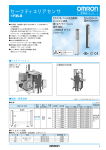
シングルビームセーフティセンサ
警告
正しい取扱いをしなければ、この危険のために、軽傷・
中程度の傷害を負ったり万一の場合には重傷や死亡に
至る恐れがあります。また、同様に重大な物的損害をも
たらす恐れがあります。
25.4
E3ZS-T81A
10.8
●警告表示の意味
形
■特性図
外部寸法図
安全上のご注意
10゚
0V
端子へ接続
(注1)
(注1)
・安全カテゴリ2で使用される場合は、F3SXのB1モジュールの各端子に正しく接
続してください。他のモジュールには接続しないでください。
・詳しくは、
F3SXのユーザーズマニュアルを参照してください。
(注2)
・受光器の桃色線は、必ずDC24Vに接続して使用してください。
(注3)
・E3ZSをF3SXと接続せず、
かつテスト入力を使用しない場合は、0Vに接続
してください。
■タイムチャート
●
出力モードとタイムチャート
入光時ON(Light ON)
タイムチャート
〔技術のお問い合わせ時間〕
■営業時間:9:00∼12:00/13:00∼19:00
(土・日・祝祭日は17:00まで)
■営 業 日:年末年始を除く
上記フリーコール以外に 055-982-5002 (通話料がかかります)
におかけいただくことにより、
直接センシング機器の技術窓口につながります。
タイムチャート
〔営業のお問い合わせ時間〕
■営業時間:9:00∼12:00/13:00∼17:30
■営 業 日:土・日・祝祭日/春期・夏期・年末年始休暇を除く
●FAXによるお問い合わせは
お客様相談室 FAX055-982-5051
●その他のお問い合せ先
納期・価格・修理・サンプル・承認図は貴社のお取引先、
または貴社担当オムロン営業員にご相談ください。
R
・F3SXは20ms毎に自己診断を行っています。
(〒141-0032)
携帯電話・PHSなどではご利用いただけませんので、
その場合は下記電話番号へおかけください
。
055-982-5015 (通話料がかかります)
投光タイムチャート
テスト入力 ON
OFF
投光 ON
OFF
表示 ON
(橙) OFF
東京都品川区大崎1-11-1 ゲートシティ大崎ウエストタワー14F
●営業にご用の方も、技術的なお問い合せの方も、
フリーコールにお電話ください。
音声ガイダンスが流れますので、案内に従って操作ください。
0 1 2 0 - 9 1 9 - 0 6 6 (フリーコール)
入光
しゃ光
動作表示
(橙)
点灯
消灯
制御出力 ON
OFF
●
営業統轄事業部
6.7dia
Lens
31
15.5
Always maintain a safe distance between the E3ZS and a
hazardous part of a machine. Be sure to refer to the related
standards (EN999) for the calculation of safety distance.
Response time
( )
Control output
Transistor output PNP, load current 100mA max
Output residual voltage of 1V or less
(when load current is less than 10mA)
Output residual voltage of 2V or less
(when load current is from 10 to 100mA)
(except for voltage drop due to cable extension)
When the E3ZS is used as a part of safe
apparatus or safe systems Category2(EN954-1),
use it with F3SX.
● SUITABILITY FOR USE
OMRON shall not be responsible for conformity with any standards,
codes, or regulations that apply to the combination of the product in
the customer's application or use of the products.
At the customer's request, OMRON will provide applicable third
party certification documents identifying ratings and limitations of
use that apply to the products. This information by itself is not
sufficient for a complete determination of the suitability of the
products in combination with the end product, machine, system, or
other application or use.
The following are some examples of applications for which
particular attention must be given. This is not intended to be an
exhaustive list of all possible uses of the products, nor is it intended
to imply that the uses listed may be suitable for the products:
Outdoor use, uses involving potential chemical contamination or
electrical interference, or conditions or uses not described in this
instruction sheet.
Nuclear energy control systems, combustion systems, railroad
systems, aviation systems, medical equipment, amusement machines,
vehicles, safety equipment, and installations subject to separate
industry or government regulations.
Systems, machines, and equipment that could present a risk to life or
property.
Receiver
Do not install the E3ZS in a location where it can be affected by
wall reflections to avoid detection failure, which may result in
serious injury.
When using multiple sets of E3ZS, arrange them to prevent mutual
interference. Failure to do so may cause the sensor not to detect,
resulting in serious injury.
The E3ZS does not offer protection to the operator’s body from
projectiles existing the hazardous area. Proper means of
mechanical guarding must be provided to ensure protection from
these potentially hazardous projectiles.
Dimensions and weights are nominal and are not to be used for
manufacturing purposes, even when tolerances are shown.
● ERRORS AND OMISSIONS
The information in this document has been carefully checked and is
believed to be accurate; however, no responsibility is assumed for
clerical, typographical, or proofreading errors, or omissions.
● COPYRIGHT AND COPY PERMISSION
This document shall not be copied for sales or promotions without
permission.
This document is protected by copyright and is intended solely for
use in conjunction with the product. Please notify us before copying
or reproducing this document in any manner, for any other purpose.
If copying or transmitting this document to another, please copy or
transmit it in its entirety.
Operation limit
Enclosure ratings
Light source
Indicators
Emitter : Orange / Light emission
Receiver : Green / Stability, Orange / Operation
Circuit protection
Weight
Output short-circuit and power supply reverse polarity
Approx. 120g (1set)
When using E3ZS by itself:
EN954-1 (Category 1)
IEC60947-5-3 (PDF-D)
UL508
When E3ZS is connected to F3SX:
IEC61496-1 Type2 ESPE
IEC61496-2 Type2 AOPD
EN954-1 (Category 2)
UL508
UL61496-1 Type2 ESPE
UL61496-2 Type2 AOPD
・Instruction sheet
Applicable
standards
Accessories
Operation
indicator
Green
Y Operating Range [mm]
D
5°
L
Distance between emitter and
receiver( Operating range L )
Minimum installation
distance D
0.2 to 3 m
0.27 m or more
■ INFLUENCE OF MUTUAL INTERFERENCE
When installing two or more E3ZSs to each other, considerations must
be made to prevent mutual interference.
・Install so that any E3ZSs emit in the opposite directions (See below).
Emitter
Receiver
Receiver
Emitter
Emitter
Receiver
・Install a light interrupting wall in between sensors.
・Install the E3ZSs facing away from the one another to
eliminate mutual interference.
■ ACCESSORY (OPTIONAL)
● Mounting
Bracket (Model E39-L104)
R2
0
14゚
3.4
6
Main
circuit
Blue
Connect to 0V
terminal
(Note 1)
Light emittion
indicator
Main
circuit
Emitter
2. Do not install the E3ZS in water.
Brown
(Note 3)
3. To extend the cable, use a wire of cross-sectional area 0.3mm2 or
more. However do not extend it more than 100m.
0 to 20
5.0
100
Peak voltage value
(2) Class 2 power supply unit that conforms to UL1310
(3) Circuit (class 2 circuit) with 30Vrms (42.4V peak) or less of
maximum voltage, and which uses a class 2 transformer that
conforms to UL1585 as its power supply
7. This is a class A product. In residential areas it may cause radio
interference. In which case the Responsible Person may be required
to take adequate measures to reduce interference.
Connect to
24V DC terminal
10゚
(Note 1)
Pink
Blue
More than 20,
up to 30
3
2-φ
(Note 1)
・Areas exposed to vibration or shock levels higher than specification
provisions;
Maximum current rating
(A)
(Note 1)
Connect to cont
output terminal
・Areas in the presence of substances, such as heavy smoke or
particulate matter, that may deteriorate product quality;
6. Power supply specifications
For combined DC power supply, use the following UL certified
products:
(1) Limited voltage current circuit that conforms to UL508
Circuit with a power supply that consists of a secondary coil of
an insulated transformer that satisfies the following conditions:
-Maximum voltage (with no load) : 30Vrms (42.4V peak) or less, and
8A or less (including short-circuit), or
-Maximum current
:
When limited by a circuit
protector (fuse, etc.) with the
ratings shown in the table below
16±0.1
Connect to
24V DC terminal
(Note 2)
Pink
Black
4.5
29
(Note 1)
Brown
Orange
・Areas with high-humidity where condensation is likely to occur;
5. When cleaning, avoid using thinner, benzene or acetone.
12
5°
PNP output
Output mode : ON when incident (Light ON)
Receiver
4. Be careful not to exceed a tightening torque of 0.5 Nm. Also, if it is
not tight enough, vibration may cause it to come loose.
10
■ INFLUENCE OF REFLECTIVE SURFACES
●
Stability
indicator
・Areas where the product may come in direct contact with water, oil,
and chemicals;
8
Install the E3ZS with minimum distance D (given below) away from
reflective surfaces (highly reflective surfaces) such as metal walls, floors,
ceilings, and work pieces
Reflective Surfaces
Output / Input circuit
1. Do not install the E3ZS in the following environments:
6
Distance [m]
Note : When using multiple sets of E3ZSs, be sure to
confirm that mutual interference is not occurred.
■ CIRCUIT DIAGRAM
Precautions for Correct Use
No-load voltage
(V peak)
4
R25.4
● DIMENSIONS AND WEIGHTS
Durability
7. Be sure to dispose of the E3ZS as industrial waste.
・Areas exposed to corrosive, flammable or explosive gases;
Product specifications and accessories may be changed at any time
based on improvements and other reasons. Consult with your
OMRON representative at any time to confirm actual specifications
of purchased product.
Operation limit
6. Do not disassemble, repair or modify the E3ZS.
NEVER USE THE PRODUCT FOR AN APPLICATION
INVOLVING SERIOUS RISK TO LIFE OR PROPERTY
WITHOUT ENSURING THAT THE SYSTEM AS A WHOLE
HAS BEEN DESIGNED TO ADDRESS THE RISKS, AND THAT
THE OMRON PRODUCTS ARE PROPERLY RATED AND
INSTALLED FOR THE INTENDED USE WITHIN THE
OVERALL EQUIPMENT OR SYSTEM.
● CHANGE IN SPECIFICATIONS
2
1000V AC, 50/60Hz for 1 min.
10∼55 Hz, 1.5mm double amplitude,
each X, Y, Z direction , 2 hours
10∼55 Hz, 0.7mm double amplitude,
each X, Y, Z direction , 50 min.
500m/s2 (approx. 50G),
each X, Y, Z direction for 3 times
100m/s2 (approx.10G),
each X, Y, Z direction for 1,000 times
IEC standard IP67
Red LED
Durability
4. Do not remove the label (yellow) from the sensor. Doing so may
violate the specifications.
5. Wire the cable so that it has some slack and does not prevent
personnel or object passage.
Allow some leeway for the wires and do not tight the wires when
connection cable to F3SX, and confirm that any cable may not block
the movements of workers or objects.
0
20MΩ or more (by 500V DC megger)
Insulation resistance
2. When used in combination with the F3SX safety controller, make
sure that the B1 module is properly connected.
3. A load must not be shorted. A load must not be used with current
higher than the rating. Do not apply the reversed supplied voltage.
Be sure to route the E3ZS cable separated from high-potential power
line or through an exclusive conduit.
0.1
Operating : 35∼85% RH, Storage : 35∼95% RH
(not freezing or condensation)
Ambient humidity
Vibration
resistance
1. Read this instruction sheet thoroughly to understand before using the
product.
Operating : -10∼55℃, Storage : -10∼70℃
(not freezing or condensation)
Ambient temperature
Do not connect the E3ZS to an AC or DC power supply with higher
voltage than nominal DC24V. Otherwise the sensor may explode,
burn, or cause electric shock. The power supply must conform to
regulatory requirements and standards, regarding EMC and
electrical equipment safety, of the country where the E3ZS is
installed. For example, the power supply must fulfill EN60742
requirements for double insulation and must conform to EMC
Directive and Low Voltage Directive in EU.
Precautions for Safe Use
100ms
Illumination intensity
Incandescent lamp : 3000 lx max.
Sunlight
: 10000 lx max.
Ambient illumination
Dielectric strength voltage
・Areas exposed to intense interference light, such as direct sunlight;
Performance data given in this manual is provided as a guide for the
user in determining suitability and does not constitute a warranty. It
may represent the result of OMRON’
s test conditions, and the users
must correlate it to actual application requirements. Actual
performance is subject to the OMRON Warranty and Limitations of
Liability.
( )
Power reset time
Shock
resistance
1
DC-13 (Control of electromagnets)
22.5 to 24V DC : Emitting OFF
(Source current : 3mA max)
Open or 0 to 2.5 V DC : Emitting ON
(Leakage current : 0.1mA max)
When the E3ZS is used as a part of safe
apparatus or safe systems Category2(EN954-1),
use it with F3SX.
E3ZS
Wiring must be done while the power is turned OFF. Doing it with
the power ON may cause an electric shock.
Please know and observe all prohibitions of use applicable to the
products.
● PERFORMANCE DATA
( )
Test Input
(Emitter)
10
8.8
IN NO EVENT SHALL OMRON BE RESPONSIBLE FOR
WARRANTY, REPAIR, OR OTHER CLAIMS REGARDING THE
PRODUCTS UNLESS OMRON'S ANALYSIS CONFIRMS THAT
THE PRODUCTS WERE PROPERLY HANDLED, STORED,
INSTALLED, AND MAINTAINED AND NOT SUBJECT TO
CONTAMINATION, ABUSE, MISUSE, OR INAPPROPRIATE
MODIFICATION OR REPAIR.
Reflective
Panel
6
X Detection distance [m]
1.0ms (E3ZS only)
Response time depends on the F3SX.
For the details, see the users manual of the F3SX.
Utilization categories
for switching elements
5
5.8
In no event shall the responsibility of OMRON for any act exceed
the individual price of the product on which liability is asserted.
Emitter
4
13.7
Do not use the E3ZS in a reflective configuration, otherwise
detection may fail.
3
1.2
OMRON MAKES NO WARRANTY OR REPRESENTATION,
EXPRESS OR IMPLIED, REGARDING NON-INFRINGEMENT,
MERCHANTABILITY, OR FITNESS FOR PARTICULAR
PURPOSE OF THE PRODUCTS. ANY BUYER OR USER
ACKNOWLEDGES THAT THE BUYER OR USER ALONE HAS
DETERMINED THAT THE PRODUCTS WILL SUITABLY MEET
THE REQUIREMENTS OF THEIR INTENDED USE. OMRON
DISCLAIMS ALL OTHER WARRANTIES, EXPRESS OR
IMPLIED.
OMRON SHALL NOT BE RESPONSIBLE FOR SPECIAL,
INDIRECT, OR CONSEQUENTIAL DAMAGES, LOSS OF
PROFITS OR COMMERCIAL LOSS IN ANY WAY
CONNECTED WITH THE PRODUCTS, WHETHER SUCH
CLAIM IS BASED ON CONTRACT, WARRANTY,
NEGLIGENCE, OR STRICT LIABILITY.
Emitter : 15mA max.
Receiver : 20mA max.
0.2~3m
Opaque object of φ18mm or more.
Current consumption
Use an opaque test rod with 18mm in diameter and 200mm or
greater in effective length to check the detection capability. The
E3ZS cannot detect transparent materials.
● LIMITATIONS OF LIABILITY
±5°
(at 3m)
If the mode selection input line of the receiver is connected to 0V,
the output turns ON when light is interrupted (Dark ON), which no
longer configures the safety system. Be sure to connect the mode
selection input line to 24V DC to make the sensor output ON when
light is incident (Light ON).
OMRON's exclusive warranty is that the products are free from
defects in materials and workmanship for a period of one year (or
other period if specified) from date of sale by OMRON.
2
3.4
SUITABILITY FOR USE
● WARRANTY
( )
Sensing distance
Standard object
1
X
Excess Gain Ration
Through beam type
Model F3SX series
12 to 24V DC±10% (ripple p-p 10% max)
When the E3ZS is used as a part of safe
apparatus or safe systems Category2(EN954-1),
use it with F3SX.
Operating angle
Emitter
Y
3.5
© OMRON Corporation 2004 All Rights Reserved.
WARNING
6
100
■ RATINGS / PERFORMANCE
Power supply voltage
5
Mutual Interference Range
200
150
100
50
0
0
-50
-100
-150
-200
2-M3
Vinyl insulated round cord
4dia, Emitter:3core, Receiver:4core
length 2m
Detection method
Controller
4
Receiver
39
The following notice applies only to products that carry the CE mark:
Notice:
This is a class A product. In residential areas it may cause radio
interference, in which case the user may be required to take adequate
measures to reduce interference.
・When the E3ZS is used with the F3SX, the requirements of the
Category 2 (EN954-1) are satisfied.
・When the E3ZS is used without the F3SX, it corresponds to the
Category 1 (EN954-1).
・Read the F3SX users manual (SCHG-705) about the rating or other
specifications of the F3SX.
3
1.2
Manufacturer:
Omron Corporation,
Sensing Devices Division H.Q.
Industrial Sensors Division
& Application Sensors Division
Shiokoji Horikawa, Shimogyo-ku,
Kyoto, 600-8530 JAPAN
WARNING
When the single beam safety sensor model E3ZS is used as a
safety device or a part of safety systems for ensuring safety of
personnel, be sure to use it with the safety controller model F3SX
series.
2
X Detection distance [m]
Optical
axis
Indicates prohibited actions.
1
3.2
TRACEABILITY INFORMATION:
Representative in EU:
Omron Europe B.V.
Wegalaan 67-69
2132 JD Hoofddorp,
The Netherlands
17
Y
X
Y Mutual interference range [mm]
● Meanings of Alert Symbols
● Alert Statements
Thank you for selecting OMRON product. This sheet primarily describes precautions required in installing and
operating the product.
Before operating the product, read the sheet thoroughly to
acquire sufficient knowledge of the product. For your convenience, keep the sheet at your disposal.
8
20
Stability indicator(Receiver only)
Emitter
Receiver
Sensing Range
200
150
100
50
0
0
-50
-100
-150
-200
Excess gain ration
INSTRUCTION SHEET
Operation indicator(Receiver only)
Light emittion indicator(Emitter only)
2.1
SINGLE BEAM SAFETY SENSOR
WARNING
Indicates a potentially hazardous
situation which, if not avoided, will
result in minor or moderate injury, or
may result in serious injury or death.
Additionally there may be significant
property damage.
25.4
E3ZS-T81A
10.8
● Meanings of Signal Words
Model
■ ENGINEERING DATA
DIMENSIONS
10.4
3.54
Precautions on Safety
Connect to test
input terminal
Connect to 0V
terminal
(Note 1)
(Note 1)・When the E3ZS is used as a part of safe apparatus or safe
systems Category2(EN954-1), connect to the B1 module of the
F3SX. Do not connect to the other modules.
・For the details, see the users manual of the F3SX.
(Note 2)・Be sure to connect the ''Mode selection input'' to 24V DC terminal.
(Note 3)・When the E3ZS is used without being connected to F3SX, test
input should be connected to 0V.
■ TIMING CHART
● Output
mode and timing chart
On when incident (Light ON)
Timing chart
Light incident
Light interrupted
Indicator Green
Red
Control ON
output OFF
● Emitting
EUROPE
OMRON EUROPE B.V. Sensor Business Unit
Carl-Benz Str.4, D-71154 Nufringen Germany
Phone:49-7032-811-0 Fax: 49-7032-811-199
timing chart
Timing chart
Test input
ON
OFF
Light emission ON
OFF
Indicator
ON
(Orange)
OFF
・The F3SX executes a periodic self-diagnosis every 20 ms.
NORTH AMERICA
OMRON ELECTRONICS LLC
One Commerce Drive Schaumburg,IL 60173-5302 U.S.A
Phone:1-847-843-7900 Telephone Consultation
1-800-55-OMRON Fax : 1-847-843-7787
ASIA-PACIFIC
OMRON ASIA PACIFIC PTE LTD
83 Clemenceau Avenue,#11-01 UE Square,Singapore 239920
Phone : 65-6-835-3011 /Fax :65-6-835-2711
OMRON Corporation
n