1
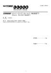
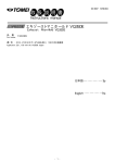
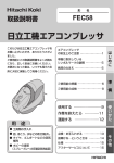
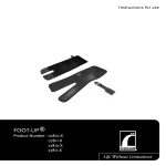
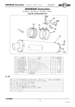
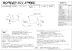
2015年1月 M20Y08-0
INSTALLATION MANUAL
エキゾーストシステム LF-VE NCECロードスター
EXHAUST SYSTEM LF-VE NCEC MX-5
品
番
メタルキャタライザーバージョン
193099
ストレートパイプバージョン
193100
Part Number
適
合
メタルキャタライザーバージョン
ストレートパイプバージョン
MAZDA CBA-NCEC LF-VE (6MT)
05-08 JDM
MAZDA CBA-NCEC LF-VE 5MT/6MT/6AT
05-08 JDM-USDM
Application
日本語・・・・・・・・・・・・・・2p
English・・・・・・・・・・・・・・6p
●この取扱説明書を良く読んでからお使いください。
●マツダの発行する整備要領書と併せてお使いください。
●取り付け後も大切に保管してください。
●販売店様で取り付けをされる場合は本書を必ずお客様へお渡しください。
TOMEI 製品のお買い上げありがとうございます。
TOMEI エキゾーストシステムは、よりスムースな排気を促すためにエキゾースト
マニホールドからフロントパイプまでの交換を前提に開発しました。
また、フロントパイプ部は用途に合わせた2種類の設定を行っています。
・性能向上とクリーンエアを両立させたメタルキャタライザー仕様
・排気効率を重視した競技専用のストレートパイプ仕様
●
●
●
●
Please carefully read this manual prior to installation.
Please also refer to the MAZDA Service Manual with this Manual.
After the installation has been completed please keep this manual for future reference.
If the install was done in a shop please make sure to give this manual to the owner.
Thank you for purchasing a TOMEI product.
The TOMEI exhaust system has been specifically designed for performance gains. So for
the optimized exhaust gas flows, the Exhaust Manifold and Front Pipe have been design
together for the optimum results. So changing the Front Pipe is a pre-requisite.
We have also made 2 types of Front Pipes available.
・The Metal Catalyzer version to suit street use and to comply with the smog
emissions in Japan.
・The Straight Pipe version is purely for competition use for maximum flow efficiency.
1
部品構成
下記の内容・数量が揃っているかを確認してください。( )内は同梱されている数量です。
フロントパイプ(1)
※図はメタルキャタライザー仕様
エキゾーストマニホールド(1)
バックパイプ(1)
※図はメタルキャタライザー仕様
フロントパイプガスケット(1)
テールエンドガスケット(1)
エキゾーストマニホールドガスケット(1)フランジボルト(2) キャップボルト(2) 皿バネ(2) フランジナット(4)
メタルキャタライザー仕様のみ付属
タイラップ(2)
バンテージ(1)
ブラインドプラグ(1)
ステッカー(2)
バンテージバンド長(6)
バンテージバンド短(8)
銅ワッシャ(1)
ボルトスムースペースト(1)
自動車排出ガス試験結果証明書(1)
作業に必要な工具類
取り付けには下記が必要です。
・エンジン整備用工具一式
・トルクレンチ
・整備要領書
注意
■ストレートパイプ仕様は自動車競技専用部品です。サーキットや公道から閉鎖されたコース内に
限って使用してください。
■本品の取り付けは特別の訓練を受けた整備士が、設備の整った作業場で実施してください。
■指定する車種以外への取り付けはおやめください。本品およびエンジンを破損する恐れがあります。
■部品脱着の際には無理な力を加えないでください。部品を破損する恐れがあります。
■取り付けの際は、適切な工具、保護具を使用しないと、けがにつながり危険です。
警告
■本品の取り付けはエンジン及びエンジンルーム内が冷えた状態で行ってください。
■部品欠落による車輌の破損・火災が起こる可能性があるため、製品構成部品の取り付けは確実に
行ってください。
2
1.純正部品の取り外し
ここで記載するのは簡易手順です。各部の詳細な脱着方法は、必ず整備要領書を参照してください。
1.
2.
3.
4.
5.
6.
バッテリーマイナス端子を取り外す。
センターエキゾーストパイプを取り外す。
ストラットタワーバーを取り外す。
アンダーカバーを取り外す。
ステアリングロアシャフトを取り外す。※復帰時にずれないよう、合いマーキング位置を確認しておくこと。
エキゾーストマニホールドを取り外す。
2.TOMEIエキゾーストシステムの取り付け
【各部品の装着位置図】
同梱部品の使用箇所・締め付けトルクは下図の通りです。(指定のないボルト・ナット・ガスケットはノーマルを使用。)
<キット付属品使用箇所>
①
②
③
④
⑤
⑥
⑦
⑧
⑨
⑩
※図はメタルキャタライザー仕様
エキゾーストマニホールドガスケット
キャタライザーパイプ-バックパイプガスケット
バックパイプ-マフラーガスケット
ブラインドプラグ M18 (キャタライザー仕様のみ)
銅ワッシャ (キャタライザー仕様のみ)
キャップボルト M10
皿バネ M10
フランジボルト M10
フランジナット M10
タイラップ
※
①
O2センサー
⑩
O2センサー
⑥※
⑦
※
⑩
⑨
※ ③
⑧※
⑨
②
⑤
④
⑨
⑧※
※部分の締めつけトルクはT=35N・m (3.6kgf-m)。
また、焼きつきや固着を防止するために、付属のボルトスムースペーストを塗布してください。
【装着手順】
1. エキゾーストマニホールドに付属のバンテージを巻く。
【参考】
・バンテージは巻く前に、バンテージを水に濡らして
絞ってから使用します。
バンテージバンドは留めた後、長さに余裕がある
場合には、ニッパーなどで不要な長さをカットして
下さい。また、その際の切り口で怪我をしないよう
注意して下さい。
3
2. あらかじめ取り外したノーマルエキゾーストマニホールドから、フロント・リアの各O2センサー、
スタッドボルトを取り外し、キットのエキゾーストマニホールドに取り付ける。
この時、O2センサーがノーマルから取り外したときと前後が逆にならないように注意して取り付ける。
3. エキゾーストマニホールドを付属のガスケット①を用い、シリンダーブロックに仮止めする。
※付属ガスケット(前頁①)使用。
4. エキゾーストマニホールドのステー部を付属のボルト・皿バネ・フランジナットを使用して、仮止めする。
※付属キャップボルトM10(前頁⑥)・皿バネ(前頁⑦)・フランジナット(前頁⑨)使用。
5. 各O2センサーのカプラを取り付ける。この時、配線が各部に干渉しないよう、タイラップで車体に固定する。
※付属タイラップ(前頁⑩)使用。
6. メタルキャタライザー(またはストレートパイプ)、及びバックパイプを各ガスケット・ボルト・ナットを
用いて仮止めする。
※付属ガスケット(前頁②・③)・フランジボルト(前頁⑧)・フランジナット(前頁⑨)使用。
7. 各部のクリアランスに注意しながら、前側から順に本締めを行う。
締付トルク [T=35N・m(3.6kgf-m)]
8. 必要に応じてA/F計センサー、またはブラインドボルトの装着を行う。(メタルキャタライザー仕様のみ)
注意
・車体各部とのクリアランスや、干渉のない事を確認してから本締めを行って下さい。
なお、車両個体差により十分なクリアランスが得られない場合は、各部の取り付けボルトを
本品が動く程度に緩め、装着クリアランスを確保した後、本締めして下さい。
・エキゾーストマニホールド・およびメタルキャタライザーに油分などが付着した状態で使用すると、
汚れや焼けの原因となります。取付後は、必ず脱脂を行って下さい。
・装着・使用状況等の必要に応じて、車体各部の遮熱対策を行って下さい。
3.周辺装置の復帰
1. 純正エキゾーストマニホールド、触媒を取り外した際に外した周辺パーツを復帰する。
2. バッテリーマイナス端子を取り付ける。
4.取り付け後の確認
1. 各部に干渉がないか、再度確認する。
2. エンジンを始動し、アイドリングから約2500rpm程度まで回転を上げ、異常音がないか確認する。
装着後、マニホールドに巻き付けたバンテージが排気ガスに熱せられると一時的に
煙が発生します。換気の良い場所でエンジンを始動させて下さい。 3. 試運転を行い、再度緩みや異常音がないか確認する。 4
警告
・
・
・
・
・
緩みや干渉があると性能の低下や、周辺部品が損傷し故障の原因となるため、確認は慎重に行ってください。
排気漏れがあると、性能の低下や排気ガスによる中毒を起こす原因となり危険です。
走行中に異常を感じた場合は直ちに走行を中止し、確認を行ってください。
その場で修復を行う場合は、エンジンルーム・エキゾーストパーツが十分に冷えた状態で行ってください。
部品の脱落等が生じている場合はエンジンを再始動せず、専門業者に修理を依頼し、指示に従ってください。
注意
・ 本品を装着した際、車両仕様によってはエンジン特性に大きな変化がある場合があります。
装着後は、エンジンセッティングを確認し、必要に応じてそれらの再セッティングを行って下さい。
5.自動車排出ガス試験成績表について
・ メタルキャタライザー仕様には自動車排出ガス試験成績表の写しが同梱されています。
装着後、継続車検時において成績表の提示を求められる場合がありますので、常時車両内に保管を
して下さい。なお、この排出ガス試験成績表は本品をノーマル車両に装着した際に、道路運送車両法・
保安基準第31条「ばい煙、悪臭のあるガス、有毒なガス等の発散防止装置」の基準に適合を示す証書で
ありますが、車検合格を保証するものではありません。
また車両仕様によっては、本品に交換する事で近接排気騒音が増加し、道路運送車両法・
保安基準第30条「騒音防止装置」における基準に適合しない場合があります。
5
KIT CONTENTS
Below is the contents of this kit with the quantity listed in brackets ().
Front Pipe (1)
※ Shown is the Metal Catalyzer version
Exhaust Manifold (1)
Back Pipe (1)
※ Shown is the Metal Catalyzer version
Exhaust Manifold Gasket (1)
Flange Bolt (2)
Cap Bolt (2)
Front Pipe Gasket (1)
Tail End Gasket (1)
Dish Washer (2) Flange Nut (4)
Supplied with the Metal Catalyzer Kit
Cable Tie (2)
Thermal Bandage (1)
Cable Tie Large (6)
Cable Tie Short (8)
Blind Plug (1)
Sticker (2)
Copper Washer (1)
Bolt Smooth Paste (1)
Smog Emissions Certificate (for Japan only)(1)
REQUIRED TOOLS
These tools are the bare minimum required for the job.
・General Engine Maintenance Tools ・Torque Wrench
・Official Service Manual
CAUTION
■ This product is designed to be used for off road competition purposes only.
■ This product is to be installed by a qualified professional in a fully equipped workshop.
■ This product was designed specifically for the application specified. If the attempt was made to use
this product on another engine/car other than specified then you will risk damaging this kit and
or the engine or components related with it.
■ This product is to be installed with the appropriate tools and equipment to prevent any engine failures
and injuries or bodily harm.
WARNING
■ This product is to be installed when the engine and engine bay is cold.
■ Please be sure that all parts are fitted correctly to avoid any possible fire risk hazards.
6
1. REMOVING THE STOCK ASSEMBLY.
This manual only provides the simple instructions. For more details please refer to the vehicles
official service manual.
1.
2.
3.
4.
5.
Disconnect the battery's negative terminal.
Remove the center exhaust pipe.
Remove the strut tower bar.
Remove the undercover protector.
Remove the lower steering shaft.
※Use a paint pen to mark the correct location so as to prevent misalignment later when you reconnect it.
6. Remove the exhaust manifold.
2.TOMEI EXHAUST SYSTEM INSTALLATION
【Illustration of the mounting position of each item】
The installation of each part are shown below with the torques specs as well.
(Nuts, Bolts and the stock gaskets are not specified.)
<Kit Contents Assembly>
①
②
③
④
⑤
⑥
⑦
⑧
⑨
⑩
※ These items are for the Metal Catalyzer only
EXHAUST MANIFOLD GASKET
CATALYZER PIPE - BACK PIPE GASKET
BACK PIPE - MUFFLER GASKET
BLIND PLUG M18 (FOR THE CATALYZER KIT)
COPPER WASHER (FOR THE CATALYZER KIT)
CAP BOLT M10
Disc Springs M10
Flange Bolt M10
Flange Nut M10
Cable Tie
※
①
O2 Sensor
⑩
O2 Sensor
⑥※
⑦
※
⑩
⑨
※ ③
⑧※
⑨
②
⑤
④
⑨
⑧※
※Torque Specs : T=35N・m (3.6kgf-m).
Apply the bolt smooth paste to prevent the parts sticking to each other.
【INSTALLATION PROCEDURE】
1. If you want to use the Thermal Bandage wrap, now is the time to use it.
Wrap your headers with the bandage as shown.
【REFERENCE】
・Soak the bandage in water to soften, then squeeze
excess water prior to wrapping the header.
After completely wrapping the header with the
bandage, cut off any unwanted excess with nippers.
Take care as to prevent any injuries.
7
2. Remove both A/F sensors from the stock unit (front and rear). Then remove the stud bolt from the
Stock unit. Make sure as not to get them mixed up (marking them will help).
3. Use the supplied exhaust manifold gasket ①, fit the exhaust manifold to the cylinder block first.
※The Gasket is supplied in the kit (Ref: ① on the previous page).
4. Use the Flange Nut, Disc Spring and Bolts that are supplied with the Exhaust Manifold, then fit the
manifold bracket.
※M10 Cap Bolt (⑥ on previous page), disc spring (⑦ on previous page) and Flange Nut (⑨ on
previous page) are used.
5. Install a coupler on each A/F sensor. Check the wiring for any signs of interference, secure the wires
in place with a cable tie.
※Cable Ties (⑩ previous page) are used.
6. Install the Metal Catalyzer (or Straight Pipe) , by using the nuts, bolts and gasket.
※Gasket (②/③ on the previous page) Flange Bolt (⑧ on the previous page) and Flange Nut
(⑨ on the previous page) are used.
7. While paying attention to the clearance of each part, starting from the front to do the final tightening
Torque Specs [T=35N・m(3.6kgf-m)]
8. Connect the A/F Sensor or if not required, use the blind bolt to seal it. (Metal Catalyzer Model Only)
CAUTION
・During final assembly and tightening of all parts together, check to be sure that nothing comes into
contact with other body parts that may cause some interference.
In some cases, there may not be sufficient clearance due to individual vehicle differences. In such case,
loosen all the products bolts of each component after mounting them, you can then re-adjust to suit
before finally tightening all bolts.
・If any signs of dirt, grim and oil is found on the exhaust system after installation, thoroughly clean it
all off before starting the engine.
・Depending on usage and users preference, you can then apply any thermal insulation to the other
body areas.
3.RETURNING AUXILARY PARTS
1. Re-install any other parts that you intend to re-use that was removed earlier.
2. Reconnect the battery's negative terminal.
4. INSTALLATION VERIFICATION
1. Check to be sure that there are no interference with any part.
2. Start the engine, have it idle and then revved up to 2500rpm to check for any abnormal sounds.
Start the car in a well ventilated area as there will be gases coming from the newly installed
Thermal Bandage on the Exhaust Manifold once heated up.
3. Have a slow speed test drive to check for any loose items or unusual noises again.
8
WARNING
・ Poor installation can result in loose parts and/or interference which can cause damages to other
peripheral parts. So please check thoroughly.
・ Any signs of exhaust leaks must be addressed. It can pose a health risk and also poor performance.
・ If you find any signs of abnormality in the car, stop the car immediately and check for faults.
・ If additional repairs are required, please do so when the engine is cold to avoid any burns or safety risks.
・ If any part has come off the car, do not restart the engine, just call your local Professional to have
it serviced.
CAUTION
・ Once installed on the vehicle, since these are non Mazda genuine parts, the engine characteristics
will change. After installation, please have a professional check the engines settings. As correction
may be required to suit the new setup.
5. SMOG EMISSION CERTIFICATE
・ The Japan smog emissions certificate comes supplied with the Metal Catalyzer kit version.
Once the product has been installed, this certificate may be required to be presented during
the renewal of the vehicles registration. So please keep it in the vehicle at all times.
The vehicles operational noise level will be much higher which may not comply to the Japan
Road & Safety Standards Section 30 of the Road Vehicles Act "Noise Control System".
9
10
11
株式会社 東名パワード
〒194-0004 東京都町田市鶴間1737-3
TEL : 042-795-8411(代)
FAX : 042-799-7851
1737-3 Tsuruma Machida-shi Tokyo 194-0004 JAPAN
TEL : +81-42-795-8411 (main switchboard)
http://www.tomei-p.co.jp
この製品に関わる取り付け、操作上のご相談は上記へお願いします。
営業時間:月~金(祝祭日、年末年始を除く)9:00~18:00
If you have any questions in regards to the installation of this product,
please contact your local authorized Tomei Powered distributor.
OPEN: Monday - Friday (National holidays and public holidays excluded). 09:00 - 18:00
エキゾーストシステム LF-VE NCEC ロードスター取扱説明書 2015年1月 M20Y08-0
EXHAUST SYSTEM LF-VE NCEC MX5 INSTALLATION MANUAL 2015.1 M20Y08-0
12