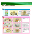
1
2015年1月 M20K06-0
取扱説明書
INSTRUCTIONS MANUAL
等長エキゾーストマニホールド EJシングルスクロール
Equal Length Exhaust Manifold for EJ Single scroll turbin
品
番
:193105
適
合
:GC8/GDB A,B EJ25およびEJ20 シングルスクロールタービン搭載車
Part Number
Application
日本語・・・・・・・・・・・・・・2p
English・・・・・・・・・・・・・・9p
●この取扱説明書を良く読んでからお使いください。
●富士重工業の発行する整備要領書と併せてお使いください。
●取り付け後も大切に保管してください。
●販売店様で取り付けをされる場合は本書を必ずお客様へお渡しください。
TOMEI 製品のお買い上げありがとうございます。
TOMEIエキゾーストマニホールドは、排気干渉を抑えたスムーズな排気を促す等長設計。
材質にはSUS304ステンレス材を使用することで軽量化、耐久性の向上を実現しました。
●
●
●
●
Installation of the production is to be carried out after the instructions are carefully read.
For further reference, compare this instruction sheet with the authentic Fuji Heavy Industries workshop manual.
After installation, keep this copy for future reference.
Be sure to give a copy of this instruction manual to the customer.
Thank you for purchasing another quality TOMEI product.
The TOMEI Exhaust Manifold has been developed to optimize high exhaust flow with minimal resistance.
The super light weight material is made from durable SUS304 stainless steel.
- 1 -
部品構成
下記の内容・数量が揃っているかを確認してください。( )内は同梱の数量です。
ガスケット(マニ-サポートパイプ間)(1)
ガスケット(サポートパイプ-T/C間)(1)
エキゾーストマニホールド本体(1)
ワッシャー(3)
銅ワッシャー(2)
ナット(3)
スタッドボルト(5)
ブラインドボルト(1)
ガスケット(ヘッド-マニ間)(2)
ステッカー (2)
ボルト(M12×1.25) (1)
ボルトスムースペースト(1)
バンテージバンド長 (3)
キャップボルト(M10×1.5) (3)
バンテージ(1)
バンテージバンド短 (8)
作業に必要な工具類
取り付けには下記が必要です。
・エンジン整備用工具一式
・トルクレンチ
・整備要領書
・タイラップ等の結束バンド
注 意
■本品は自動車競技専用部品です。サーキットや公道から閉鎖されたコース内に限って使用してください。
■本品の取り付けは特別の訓練を受けた整備士が、設備の整った作業場で実施してください。
■指定する車種以外への取り付けはおやめください。本品およびエンジンを破損する恐れがあります。
■取り付けの際は、適切な工具、保護具を使用しないと、けがにつながり危険です。
警 告
■本品の取り付けはエンジン及びエンジンルーム内が冷えた状態で行ってください。
■部品欠落による車輌の破損・火災が起こる可能性があるため、製品構成部品の取り付けは確実に行ってください。
- 2 -
1.スタッドボルト取り付け
付属のスタッドボルトをTOMEIエキゾーストマニホールドのサポートパイプにダブルナットにて取り付ける。
①スタッドボルトの、ねじ部分が長い側にダブルナットを
固定する。
ダブルナット取付側
サポートパイプ側
長
短
②TOMEIサポートパイプにスタッドボルトを取り付ける。
③トルクレンチを用いてナットを締め付ける。
規定トルク
2.5kgm~3.0kgm
(24.5~29.4 N・m)
④ダブルナットを取り外す。
注 意
ナットを取り外す時、絶対にボルトを動かさないように
注意する。
ボルトが動いた時は上記作業をやりなおす。
※ダブルナットを使用しながら取り付け
※ボルト取り付け方向の長さに注意
※焼き付きや固着を防止する為、付属のボトルス
ムースペーストを塗布してください。
2.サブフレームの取り外し(GDB A,Bのみ)
取り付ける車輌がGDB A,Bの場合は事前にサブフレームを取り外して
ください。 (※整備書を参考に取り外しを行ってください。)
- 3 -
3.純正エキゾーストマニホールドの取り外し
1.バッテリーマイナス端子を取り外す。
2.純正エキゾーストマニホールドASSYを取り外す。(※整備書を参考に取り外しを行ってください。)
【 参 考 】
サポートパイプ取り外しの際、サポートパイプとメンバーのクリアラ
ンス状態により、車両によってうまく外れない場合があります。
エンジン下部のマウント取り付けナット2ヶ所(左図参照)を外し、ガ
レージジャッキなどを用いてエンジンを下部から5~10cm持ち上げ
る事で取り外すことができます。
注 意
・ガレージジャッキなどを使用しエンジンを持ち上げる際、車両側のジャッキなどを当てる箇所に注意してください。
柔らかい部位に当て、持ち上げると歪みや破損につながります。
・エンジンを持ち上げる際は、必ずウマを使用し安全に注意して行ってください。
- 4 -
4.TOMEIエキゾーストマニホールドの取り付け
【各ボルト・ガスケットの装着位置図】
同梱のボルト、ガスケットの使用箇所は下図の通りです。
④
ナット(ノーマル使用)
①
⑤
T=35N・m(3.6kgf-m)
⑩
⑩
T=35N・m(3.6kgf-m)
②
⑩
※
③
⑨
※⑧
⑥
⑨
③
⑦
⑧
※
①
②
③
④
⑤
⑥
⑦
⑧
⑨
⑩
サポートパイプ-T/C間ガスケット
マニ-サポートパイプ間ガスケット
ヘッド-マニ間ガスケット
ボルト M12×1.25
銅ワッシャー
ブラインドボルト
銅ワッシャー
ボルト M10×1.5
ワッシャー
ナット
※部分には焼き付きや固着を防止する為、
付属のボルトスムースペーストを塗布して
ください。
⑨
⑧
※
ナット(ノーマル使用) T=30N・m(3.1kgf-m)
- 5 -
【装着手順】
1.サポートパイプを付属のガスケットを用い、ターボチャージャーに仮止めする。
2.エキゾーストマニホールドをシリンダーヘッドに合わせる。
このときエキゾーストマニホールドが、サポートパイプ、シリンダーヘッドにうまく合わない場合は、マニホールドの中間
差し込み部分で調整することができます。
②
①
・マニホールド中間差し込み部分のボルト(上図①部分)4カ所ゆるめる
・差し込み部分(上図②部分)をスライドさせ位置を調整する
・調整後、ゆるめたボルトを締める(トルク T=5.8~6.8N・m(0.6~0.7kgf-m))
3.干渉部分の対策加工を行う。
①
部分を切削
②
① アンダーカバーを上図のようにマニホールドに干渉しないよう切断する。
② フロントバンパー内部に収納されたハーネス及び、電動ファンのハーネスをできるだけ外側へ逃がす状態で
タイラップなどで固定し干渉を避ける。
- 6 -
4.付属のバンテージを巻く
一旦エキゾーストマニホールドとサポートパイプを取り外し、付属のバンテージを巻き付け、バンテージバンド、留め金を
使用し固定する。
【 参 考 】
・バンテージは巻く前に、バンテージを
水に濡らし、絞ってから使用します。
バンテージバンドは留めた後に長さに
余分がある場合は、ニッパーなどで
不要な長さをカットしてください。
また、その際の切り口でけがをしない
よう注意してください。
5.エキゾ-ストマニホールドをシリンダーヘッドにガスケットを挟み仮止めする。(付属ガスケット:前頁③使用)
6.サポートパイプとエキゾーストマニホールドを各部にガスケットを挟み固定する。(付属ガスケット:前頁①・②使用)
7.エキゾーストマニホールドを本締めする。 【締め付けトルク:T=30N・m(3.1kgf-m)】
8.サポートパイプを本締めする。【締め付けトルク:T=35N・m(3.6kgf-m)】
9.サブフレームを取り付ける(GDB A,Bのみ)
(1) サブフレームを仮止めし、サブフレームとエキゾースト
マニホールドとのクリアランスを確認する。
(※左図
部分)
(2) クリアランスが10mm未満の場合は、サブフレームを
いったん取り外し、クリアランスが10mm程度になるよ
う切削する。
(3) サブフレームを復帰する。
10.純正エキゾーストマニホールドを取り外した際に同時に外した周辺パーツを復帰する。
11.バッテリーマイナス端子を取り付ける。
注 意
エキゾーストマニホールド、サポートパイプに油分などが付着した状態で使用すると、汚れやヤケの原因となります。
取り付け後は必ず脱脂を行ってください。
- 7 -
5.取り付け後の確認
1.エキゾーストマニホールド及び、サポートパイプに周辺部品、配線の干渉がないか確認する。
2.エンジンを始動し、排気漏れがないか確認する。
注 意
装着後、マニホールドに巻き付けたバンテージが排気ガスにより熱せられると一時的に煙が発生します。
換気の良い場所でエンジンを始動させてください。
警 告
・干渉があると周辺部品が損傷し、車両火災や故障の原因となる為確認は慎重に行ってください。
・排気漏れがあると、性能の低下や、排気ガスによる中毒を起こす原因となり危険です。
- 8 -
Kit Contents
Please confirm that your outlet pipe kit is complete. Each package is label showing the quantity of each package.
Gasket (With Mani-support pipe)(1)
Gasket (With Support pipeT/C) (1)
Exhaust Mani-hold main part(1)
Washer (3)
Copper washer (2)
Stud bolt(5)
Gasket (With Head-mani)(2)
Nut (3)
Sticker (2)
Bolt (M12×1.25) (1)
Bolt smooth paste (1)
bandageband long (3)
Cap bolt (M10×1.5) (3)
Bandage (1)
bandageband short (8)
Blind bolt (1)
Tools required for work
The following tools are necessary for the installation.
・Tool kit for maintenance
・Torque wrench
・Servicing instruction
・Banding TY-RAP
Caution
■This product is only for vehicle use under a closed circuit and for public roads.
■The technician for this installation must be a licensed mechanic, which holds a thorough understanding for
installations.
■Only install this product on the specific model as stated above. If installed on a different model, possible
engine damage will occur.
■Only use the proper tools during installation.
If wrongful tools are used, possible injury will occur.
Warning
■Install this item when the engine is cold.
■Install all kit components of a possible engine fire may result.
- 9 -
1.Stud bolt installation
The studs are to be installed in the support pipe of Tomei Exhaust Manifold with a double nut.
①A double nut is threaded onto the longer side of the
threaded stud.
Double nut installation side
Support pipe side
Length
short
②Thread the stud bolt into the TOMEI support pipe flange
③The nut is tightened with a torque wrench.
Specified torque
2.5kgm - 3.0kgm
(24.5 - 29.4 N・m)
④The second double nut is removed.
Caution
Never move the bolt when you detach the nut.
If the bolt still moves you will need to re-do the
procedure again.
※Be careful not to loosen the stud bolt when removing
the double nut.
※Be careful to make sure that the longer thre aded
stud area is pointing away fomr the flange
※Spread bolt paste to prevent burning and clinging.
2. Removal of the sub-frame (Only GDB A and B)
When the vehicle is a GDB A and B, remove the sub-frame in advance.
(Refer to the maintenance book).
- 10 -
3. Removal of genuine Exhaust Manifold
1.Remove the negative battery terminal.
2.Removal of the the genuine Exhaust Manifold assembly (※Refer to the maintenance book.)
【Reference】
It may not separate well with vehicles according to
the clearance condition of a support pipe and a member
at the time of support pipe removal.
Two mount attachment nuts (refer to left figure) of
the engine lower part are removed.
And it can be removed by lifting engine for
5cm to 10cm from the lower part using a garage jack etc.
Caution
When you lift the engine using a hydralic jack., be careful of the position.
- 11 -
4.Installation of TOMEI Exhaust Manifold
【The location and position of each bolt and gasket】
The components and hardware used is labeled below.
④
Nut (normal use)
①
⑤
T=35 N-m (3.6 kgf-m)
⑩
⑩
T=35N・m(3.6kgf-m)
②
⑩
※
③
⑨
※⑧
⑥
⑧
※
⑨
③
⑦
① The gasket between
support pipe-T/C
② The gasket between
the Mani-support pipes
③ The gasket between
head-Mani
④ Bolt M12x1.25
⑤ Copper washer
⑥ Blind bolt
⑦ Copper washer
⑧ Bolt M10x1.5
⑨ Bolt M10x1.5
⑩ Nut
※Spread bolt paste to prevent burning
and clinging.
⑨
⑧
※
Nut (normal use) T=30 N-m (3.1 kgf-m)
- 12 -
【Installation procedure】
1. Connect the temporary joint of the Support pipe to a turbocharger by using a gasket.
(An attached gasket: Previous page ① use)
2.The Exhaust Manifold is matched to the cylinder head.
At this time, when alignment isnt good, adjust the exhaust manifold at the middle joint until alignment is best.
②
①
・Loosen the manifold (left figure ①)bolt at four locations.
・Slide a plug portion (left figure ②), and adjust the position.
・Tighten the loosened bolt after adjustment. (torque T=5.8>6.8N・m(0.6 - 0.7kgf-m))
3. Measure the under cover if there is interference.
①
The part is cut.
②
① Cut the undercover at manifold area, as shown in the above figure.
② Secure with TY-RAP so that under cover is not loose or in the way of other moving objects
- 13 -
4. Roll Attached bandage onto piping.
The new Exhaust Manifold and a Support pipe are again removed.
Wind Bandage of the attachment, and fix with Bandage-band clasps.
【Reference】
・Apply a small amount of water
before wrapping it.
Cuts excess lengths with
cutters
In that case of using sharp tools
be careful of sharp edges.
5. Insert a gasket into the cylinder head exhaust port.
(An attached gasket: Previous page ③ use)
6. Insert a gasket into a Exhaust manifold and a Support pipe and fix Exhaust manifold and a Support pipe.
(An attached gasket: Previous page ①and② use)
7. Fully tighten Exhaust Manifold. 【Tightening torque: T=30N・m (3.1kgf-m)】
8. Fully tighten Support pipe.【Tightening torque: T=35N・m (3.6kgf-m) 】
9. Fully tighten Support pipe.(Only GDB A and B)
(1) Joint the sub-frame temporarily.
and confirm the clearance of the sub-frame
and the Exhaust Manifold.
(※left figure
part)
(2) When clearance is less than 10mm,
once remove the sub-frame.
Cut so that clearance is set to about 10mm.
(3) Return the sub-frame
10. When genuine Exhaust Manifold is removed, re-install as in the opposite manner of removal.
11. Reattach a battery negative terminal.
Caution
Remove any dirt and grime when using it with oil etc. check your exhaust manifold and the support pipe.
To remove any unwanted material after the installation.
- 14 -
5.The confirmation after attachment
1.Check to see if any parts or electrical wiring have been damaged during installation.
2.Start the engine, and confirm whether there are any exhaust leaks.
If Bandage material is wrapped around the manifold, a short termed smoke will be seen
Warning
Inhaling exhaust over a short period of time will cause injury.
Please make sure your working area is well ventilated.
- 15 -
●この製品に関わる取り付け、操作上のご相談は上記へお願いします。
営業部
042-795-8411
営業時間:月~金(祝祭日、年末年始を除く)9:00~18:00
If you have any questions in regards to the installation of this product,
please contact your local authorised Tomei Powered distributor.
OPEN: Monday - Friday (National holidays and public holidays excluded). 09:00 - 18:00
〒194-0004 東京都町田市鶴間1737-3
TEL 042-795-8411(代)
FAX 042-799-7851
http://www.tomei-p.co.jp
1737-3 Tsuruma Machida-shi Tokyo 194-0004,JAPAN
Tel: +81-42-795-8411(main switchboard) /Fax: +81-42-799-7851
等長エキゾーストマニホールド EJシングルスクロール 取扱説明書
- 16 -
2015年1月 M20K06-0