1
■ Specification
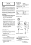
GS-503
INSTRUCTION MANUAL
Thank you very much for purchasing ONO SOKKI GS-503 Linear Gauge Sensor. To ensure
proper operation, read this manual carefully before use.
Type code
Measuring range
Measurement unit
Indication accuracy
Maximum response speed
Measurement force
GS-503
50 mm
10 µm
10 µm (+20°C)
1 (4) * m/s
max. 1.3 N
* Measurement force can be changed by option.
4.5 to 6 VDC
approx. 65 mA (under 5 V)
two-phase square wave signal
Phase difference: 90°±20° (under 5 VDC)
Hi: 4.5 to 6 V (in no-load condition)
Lo: max. 0.4 V
Supply voltage
Current consumption
Output signal
After reading, keep this manual in a convenient place so that you can consult it at any time.
■ Precautions for Use
(1) Do not disassemble the linear gauge sensor, or failure might be resulted.
If the cover of the linear gauge sensor or the seal bonded inside the rear cover is removed,
chips, cutting oil, dust or other foreign matter may enter to cause failure. Do not remove them
to open. Be careful that if the cover or the seal is removed, the product cannot be warranted
even within the warranty period.
P
Signal 2
When the spindle is pushed in
Terminal connector
(4) Replacement of probe
When replacing the probe, be careful not to apply torsional
force on the spindle. If the probe cannot be loosened, wind
a rubber band round the spindle, and turn the probe surely
holding the spindle via the rubber band. To mount the probe,
do the same way.
■ Operation of the spindle
When the spindle comes out
R03-PB6M (from Tejimi Musen)
Gauge sensor
Connector
Blue
Signal 1
(2) Keep the spindle free from oil or dust
If oil or hand grease is applied or stuck on the spindle, it cannot move smoothly. Be sure to
avoid oiling the spindle or touching it by bare hand.
To wipe oil (grease) or dust off the spindle, use dry soft cloth or sot cloth wetted with absolute
alcohol. (Never use benzene, thinner, gasoline, etc.)
(3) Do not apply lateral force on the spindle.
Bearing mounting face of the spindle is very precisely machined. If lateral force is applied on
the spindle or if the stem is tightened too strongly, the spindle cannot move smoothly.
GS-503 uses the spindle of carbon fiber, the flexural rigidity of which is approximately 5 times
as high as that of metal spindle, so that the spindle is improved in the strength against lateral
force. This does not mean that it is positively allowed to apply lateral force on the spindle.
But when there is a possibility that lateral force acts on the spindle during measurement, it is
recommended to use GS-503.
P=40µm
Signal 1
White
Signal 2
* Inside the
sensor, the
signal common
Signal 2
terminal is not
Power output +
connected to
the case.
Signal common
Power output -
B
Red
Power input +
Counter
Signal 1
A
C
D
Black
Signal common
Power input -
E
Green
F
Case shield
Operating temperature
Storage temperature
Cable length
+5°C to +40°C
–10°C to +55°C
approx. 1.9 m
* Can be extended to 30 m with the optional extension cable.
approx. 540 g (including cable)
Instruction manual
Mass
Accessory
Option
Finger lift
Dust-proof rubber
Gauge stand
AA-969
AA-854
ST-011, ST-022, ST-044B
(Bushing for ø10 (AA-892) is necessary)
Extension spindle, various probes
Others
*It is available when our digital gauge counter is used.
The value, whcih is written at ( ), is maximum response speed when it is combined with
our model DG-4140/4160.
■ Outside Drawing
(1) Use the dedicated lifter
If the spindle is operated directly by hand, there arises a danger that dust or oil (grease) sticks
on it to cause errors. To avoid this, it is recommended to use the release dedicated to GS-503.
Unit: mm
Signal cable
(approx. 1.9 m long)
(96)
LINEAR GAUGE SENSOR
36
0000000
20
0.01-50 mm
No.
138
Lug
2-ø6.5
ø68
(2) Use the linear gauge sensor within the maximum response speed.
The maximum response speed of GS-503 with respect to the moving speed of the spindle is
1 m/s. Moving faster than this might result in malfunction. In addition, the proper method
for making the spindle touch the object to be measured is to drop the spindle after making it
come within 1 mm from the object.
165
ø11
MADE IN JAPAN
28
ø11
ø10
ø6.5
40
46
Probe
10
29
10
7.5
The stem is finished to ø10−00.036 mm in outer diameter.
(15)
Spindle
ø5
(66.5)
Stem
■ How to Mount the Sensor
(1) Fixing by the stem
173 2
8
R
(3) Reference point of spindle
ÉIf the spindle is not made touch the reference plane, no accurate fixed point can be obtained.
For measurement, be sure to make the spindle touch the reference plane and make this pushed
condition the reference point.
21
For this fixing method, prepare a mounting hole of
ø10 +0.03
+0.01 mm, and tighten carefully so that no excess
force acts on the stem.
■ Omission of Test Qualification Issuance
Since this product has been tested through a series of strict inspections and a complete program of
quality control, issuance of the test qualification has been omitted.
Warranty
(2) Mounting by the lug
Two holes of ø6.5 mm are made on the lug that is
provided on the rear of this sensor. Using these
holes, fix the sensor by M6 screw.
1. This product is covered by a warranty for a period of one year from the date of purchase.
2. This warranty covers free-of-charge repair for defects judged to be the responsibility of the manufacturer, i.e., defects occurred
while the product is used under normal operating conditions according to descriptions in this manual and notices on the unit label.
3. For free-of-charge repair, contact either your sales representative or our sales office nearby.
4. The following failures will be handled on a fee basis even during the warranty period.
(a) Failures occurring through misuse, mis-operation, or modification
(b) Failures occurring through mishandling (dropping) or transportation
(c) Failures occurring through natural calamities (fires, earthquakes, flooding, and lightening), environmental disruption, or
abnormal voltage.
* For repairs after the warranty period expired, contact your sales representative or our sales office nearby.
*Outer appearance and specifications are subject to change without prior notice.
HOME PAGE: http://www.onosokki.co.jp/English/english.htm
WORLDWIDE
Ono Sokki Co., Ltd.
1-16-1 Hakusan, Midori-ku,
Yokohama 226-8507, Japan
Phone : 045-935-3976
Fax
: 045-930-1906
E-mail : [email protected]
ONOSOKKI
リニアゲージセンサ
■仕様
型名
GS-503
測定範囲
50 mm
GS-503
測定単位
10 µm
指示精度
10 µm(+20℃)
取扱説明書
最大応答速度
1 (4) * m/s
測定力
1.3 N以下
このたびは、小野測器の GS-503 リニアゲージセンサをご採用いただきまして、誠
にありがとうございます。本器の性能を充分に生かして、ご使用いただくために、
ご一読をお願いいたします。
また、お読みになった後も、大切に保管してください。
供給電源電圧
DC4.5 V∼6 V
消費電流
約65 mA(DC5 Vにて)
※オプションにて測定力の改造が可能
出力信号
2相方形波信号
位相差90 °
±20 (
°DC5 Vにて)
Hi:4.5 V∼6 V(無負荷時)
■ご使用に際しての注意
(1)リニアゲージセンサを分解することは、故障の原因となります。
リニアゲージセンサのカバーまたは、
裏蓋内部のシールを開けますと、
内部に
切粉や切削油などの、ゴミ、ホコリが入り故障の原因となりますので、絶対に
開けないでください。
カバーを開けたりあるいはシールをはがした場合には、
保証期間内でも保証の対象とはならなくなりますので、ご注意ください。
Lo:0.4 V以下
信号 1
信号 2
スピンドルを押し込む時
端末コネクタ
(4)測定子の交換
測定子を交換する場合には、
スピンドルにねじれ力
が加わらないように充分にご注意ください。
もし測
定子がゆるまない場合には、
図のようにスピンドル
にゴムバンドを巻き、手でしっかりとおさえて、測
定子を回してください。また、測定子を取り付ける
場合も同様に行ってください。
引き出す時
R03-PB6M(多治見無線)
(2)スピンドルは、油やゴミを嫌います。
スピンドルに注油したり、
手の脂などが付着しますと、
スピンドルの動きが悪
くなりますので、スピンドルに注油したり、素手で触ることは避けてくださ
い。
また、スピンドルに付着した油(脂)やゴミをふき取る場合には、乾いた柔ら
かい布または、無水アルコールを湿らせた柔らかい布でふき取ってください
(ベンジン、シンナー、ガソリンなどは使用しなしでください)
。
(3)スピンドルには横方向の力を加えないでください。
スピンドルと軸受の関係は、
非常に精密に加工されていますので、
スピンドル
に横方向の力を加えたり、
ステムを必要以上の力で締め付けるとスピンドルの
動きが悪くなります。
GS-503 はスピンドルにカーボンファイバを採用しており、曲げ弾性が金属ス
ピンドルの約5倍もあり、
スピンドルに対する横方向の力に対して強度が向上
しています。スピンドルの横方向に対する力を肯定するものではありません
が、特に測定中に横方向の力が加わる可能性のある場合には GS-503の使用を
お奨めします。
P=40µm
P
ゲージセンサ
コネクタ
青
信号 1
白
信号 2
電源入力 +
信号コモン
電源入力 −
赤
カウンタ
A
信号 1
B
信号 2
C
電源出力 +
D
黒
信号コモン
電源出力 −
E
緑
※センサ内では、
ケースと信号コ
モン間は接続さ
れていません。
F
ケースシールド
使用温度範囲
+5 ℃∼+40 ℃
保存温度範囲
−10 ℃∼+55 ℃
ケーブル長
約1.9 m
※オプションの延長ケーブルで30 mまで延長可能
質量
約540 g(ケーブル含む)
付属品
取扱説明書
オプション
フィンガーリフト
AA-969
防塵ゴム
AA-854
ゲージスタンド
ST-011、ST-022
ST-044B(φ10用ブッシュ AA-892必要)
その他
延長スピンドル、各種測定子
* 当社ゲージカウンタ使用時。
( )内はDG-4140/4160で使用した時の最大応答速度です。
■外観図
単位:mm
信号ケーブル(長サ約1.9 m)
(1)リフタは専用のものをご使用ください。
手で直接スピンドルを操作すると、ゴミや油(脂)の付着により誤差が出る恐
れがあります。そのため GS-503 には専用のリフタの使用をお奨めします。
165
φ11
36
0000000
20
0.01-50 mm
No.
138
耳金
2-φ6.5
φ68
(2)リニアゲージセンサの最大応答速度を守ってください。
GS-503はスピンドルの移動速度に対しての最大応答速度が1m/sとなっていま
す。この速度以上で動かしますと、誤作動をすることがあります。また、被測
定体へスピンドルを当てるときは、1mm 以内に近づけてからスピンドルを落
下させるのが、望ましい使い方です。
(96)
■スピンドルの操作について
MADE IN JAPAN
R
28
φ11
φ10
ステムの直径は φ10 −00.036 mm に仕上げられ
ていますので、φ10 +0.03
mm の取付穴を加工
+0.01
してステムに必要以上の力がかからないよ
うに締め付けてください。
φ6.5
40
測定子
46
10
29
10
(66.5)
スピンドル
φ5
7.5
(15)
ステム
■センサの取付方法
(1)ステムをつかんで固定する方法
173 2
8
(3)スピンドルの基準点について。
スピンドルを基準面に当てない状態では、正確な定点とはなりません。必ず、
スピンドルを基準面に当てて、押し込んだ状態を基準点としてください。
21
■検査合格証の省略について
本製品は、工場出荷に際して弊社の厳重な出荷検査を受け、正常に動作することが確認されておりますが、検査合格証
の発行は省略しております。あらかじめご了承ください。
■輸出または国外へ持ち出す際のご注意
本製品(役務を含む)を輸出または国外へ持ち出す際は、外国為替および外国貿易管理法の規定により、法令該当品の
場合、日本国政府(通商産業省)への輸出許可申請の手続きが必要となります。また、非該当品であっても、通関上非
該当判定書を要する場合があります。輸出または国外へ持ち出す際は、弊社までご相談ください。
(2)耳金部分による取付方法
本体背面の耳金部分にはφ 6.5 mm の穴が
2箇所設けてあります。
この穴を利用して、
M6 のネジで固定してください。
■保証規定
1.お買い上げ日から一年間は保証期間です。故障の場合
には無償にて修理いたします。
2.保証期間内であっても、次のような場合には有償修理
になります。
・使用上の誤りおよび不当な修理や改造等による故障や損傷
・お買い求めいただいた後の取り付け場所移動時などでの故障
や損傷
・火災、地震、水害、落雷、その他天災地変、公害や異常電圧
等による故障や損傷
・消耗品、予備品、付属品等の補充
3.本保証規定は日本国内においてのみ有効です。
This warranty is valid only in Japan.
*保証期間後の修理などについてご不明な場合は、お買い
求めの販売店または弊社までお問い合せください。
株式会社
小野測器
〒226-8507 神奈川県横浜市緑区白山1-16-1
お客様相談室
フリーダイヤル 0120-388841
FAX 0120-045935
Copyright © ONO SOKKI Co.,Ltd. 2005 All rights reserved.
B00001720 / IM00070602(2) 05X(MS)XXX