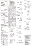
1
Z相原点
位置ポイント
それがあります。
E6C2-CWZ
( 2 )高 圧 線 、動 力 線と平 行して配 線しますと誘 導を受け誤 動 作または破 損の原 因になる場 合がありますので別 配 線をして
ください。
( 3 )使 用 電 源 にサージが 発 生 する場 合 、電 源 間 にサージアブソーバを接 続してサージを吸 収してください 。またノイズ 等
ロータリエンコーダ
φ50
0
φ25 -0.021
形
3-M4
深サ7
を避けるためにも形E6C2の配線はできるだけ短くして使用してください。
このたびは、本製品をお買い上げいただきまして、まことにありがとうございます。
ご使用に際しては、次の内容をお守りください。
・ 電気の知識を有する専門家がお取り扱いください。
・この取扱説明書をよくお読みになり、十分にご理解のうえ、正しくご使用ください。
・この取扱説明書はいつでも参照できるよう大切に保管してください。
120°
ご使用ください。
(6.59)
120°
( 4 )電 源の投 入 時 、断 時に誤パルスが生じる場 合がありますので後 続の機 器は電 源の投 入 、断 時から0 . 1 秒 後 、0 . 1 秒 前で
取扱説明書
(60)
15 5
40
10
1
( 1 )定 格 電 圧を超えて、使 用しないでください 。定 格 電 圧 範 囲 以 上 の 電 圧を印 加 すると、破 裂したり、焼 損したりするお
0
φ6 -0.021
1.6
■外形寸法図
安全上の要点
φ38
使用上の注意
*
(1)本製品は精密品で構成されていますので取扱いには十分注意してください。
*PVC耐油コード外径φ5
(18/φ0.12)
5芯
標準2m シールド付
(ラインドライバー8芯)
(2)本体には水滴や油がかからないように使用してください。
(3)電源の極性など誤配線をしないでください。破裂したり、焼損したりする恐れがあります。
(4)配線は電源OFFの状態で行ってください。
■取付寸法
(5)本体を固定し、
コード配線される場合、
コードを29.4N以上の力で引張らないでください。
(6)本体をねじ締めで固定される場合の締付トルクは0.49N・m以下にしてください。
+0.1
φ25 穴
0
φ
38
±
(7)
シャフトに過大な荷重がかからない様にしてください。破損する恐れがあります。
3-φ4.5穴
0.
2
特にチェーン・タイミングベルトおよびギヤで結合される場合は必ず一度別の軸受で受けカップリングを介して結合してください。
(8)
シャフトと相手軸との間で偏芯、偏角等がある場合(直接結合、
あるいはカップリングを介する場合共に)回転中にシャフトに過大な荷重
■種類と定格
項目
3.3Ω
電源電圧
PNPトランジスタ
(A、B、Z相とも同様)
出力信号
0V
CWZ6C
100mA以下
出力形態
電圧出力
出力容量
35mA max
DC30V
3.3Ω
max
CWZ3E
出力信号
NPNトランジスタ
(A、B、Z相とも同様)
DC5∼24V
(−+15%
5%)
DC5V(±5%)
80mA以下
E6C2-CWZ5B
+15%
DC12∼24V
(−10%
)
160mA以下
100mA以下
負荷抵抗 2kΩ
印加電圧 DC30V以下 AM26LS31相当
ソース電流 35mA max.
残留電圧 0.4V以下 シンク電流 35mA 以下 出力電流
残留電圧 0.4V以下
0.4V以下
出力電流 20mA 以下 残留電圧
Hレベル:IO=ー20mA (ソース電流 35mA)
(シンク電流35mA時) Lレベル:IS= 20mA
出力電圧
VO=2.5V 以上
VS=0.5V 以下
最高応答周波数
100kHz
出力位相差
A相、B相差 90±45゜
起動トルク
0.98N・cm以下
20mA max
50kHz
慣性モーメント
1×10⁻⁶ kg・m2以下(600P/R以下は3g・cm2 3×10⁻⁷ kg・m2以下)
0V
許容最高回転数
6000r/min
DC5V
軸 負 荷
非反転出力
AM26LS31
(A、B、Z相とも同様)
相当
反転出力
(A、B、Z相とも同様)
形 式
線色
E6C2E6C2CWZ6C,3E,5B CWZ1X
端子名
端子名
茶
電源
電源
(+Vcc) (+Vcc)
黒
出力A
出力A
白
出力B
出力B
橙
出力Z
出力Z
黒/赤
ストライプ
白/赤
ストライプ
橙/赤
ストライプ
青
使用周囲温度
−10∼+70℃
使用周囲湿度
35∼85%RH
出力B
出力Z
0V
0V
E6C2-CWZ
ROTARY ENCODER
INSTRUCTION SHEET
12
営業統轄事業部
東京都品川区大崎1-11-1 ゲートシティ大崎ウエストタワー14F
(〒141-0032)
●営業にご用の方も、技術的なお問い合せの方も、
フリーコールにお電話ください。
音声ガイダンスが流れますので、案内に従って操作ください。
0 1 2 0 - 9 1 9 - 0 6 6 (フリーコール)
携帯電話・PHSなどではご利用いただけませんので、
その場合は下記電話番号へおかけください。
055-982-5015 (通話料がかかります)
〔技術のお問い合わせ時間〕
■営業時間:9:00∼12:00/13:00∼19:00
(土・日・祝祭日は17:00まで)
■営 業 日:年末年始を除く
上記フリーコール以外に 055-982-5002 (通話料がかかります)
におかけいただくことにより、
直接センシング機器の技術窓口につながります。
〔営業のお問い合わせ時間〕
■営業時間:9:00∼12:00/13:00∼17:30
■営 業 日:土・日・祝祭日/春期・夏期・年末年始休暇を除く
●FAXによるお問い合わせは
お客様相談室 FAX055-982-5051
●その他のお問い合せ先
納期・価格・修理・サンプル・承認図は貴社のお取引先、
または貴社担当オムロン営業員にご相談ください。
IEC 60529規格 IP64
R
■OUTLINE DRAWING
Precautions for Safe Use
Model
①安全を確保する目的で直接的または間接的に人体を検出する用途に、本製品を使用し
ないでください。同用途には、当社センサカタログに掲載している安全センサをご使用く
ださい。
②下記用途に使用される場合、当社営業担当者までご相談のうえ仕様書などによりご確
認いただくとともに、定格・性能に対し余裕を持った使い方や、万一故障があっても危険
を最小にする安全回路などの安全対策を講じてください。
a)屋外の用途、
潜在的な化学的汚染あるいは電気的妨害を被る用途
またはカタログ、
取扱説明書等に記載のない条件や環境での使用
b)原子力制御設備、
焼却設備、
鉄道・航空・車両設備、
医用機械、
娯楽機械、
安全装置、
および行政機関や個別業界の規制に従う設備
c)人命や財産に危険が及びうるシステム・機械・装置
d)ガス、
水道、
電気の供給システムや24時間連続運転システムなどの
高い信頼性が必要な設備
e)その他、
上記 a) ∼ d) に準ずる、
高度な安全性が必要とされる用途
*上記は適合用途の条件の一部です。当社のベスト、総合カタログ・データシート等最新版
のカタログ、
マニュアルに記載の保証・免責事項の内容をよく読んでご使用ください。
出力A
ラジアル……50N
スラスト……30N
保護構造
0V
・外部接続時には誤配線のな
いよう注意してください。
NPNオープンコレクタ出力 ラインドライバー出力 PNPオープンコレクタ出力
3.3Ω
CWZ1X
E6C2-CWZ1X
0V
DC5∼12V
2kΩ
E6C2-CWZ6C
DC5∼12V
(−+10%
5%)
消費電流
DC5∼24V
出力信号
NPNトランジスタ
(A、B、Z相とも同様)
E6C2-CWZ3E
(1)Do not use the product in excess of the rated voltage. Applying voltage beyond the rated voltage
range may cause the product to break or burn.
(2)Avoid wiring the product's cables parallel to power lines or high-voltage lines. Doing so may cause
the product to malfunction due to induction or may cause the damage the product.
(3)If surge occurs in the power supply, connect a surge absorber between the power supply terminals
to absorb the surge.
Minimize the wiring length to prevent the product from being affected by noise, etc.
(4)Since improper pulses may occur when the power is turned on or off, use the devices connected to
this product at least 0.1 seconds before or after the power is turned on or off.
MARK FOR THE STARTING
POINT OF Z
Three,M4
Depth 7
15 5
10
(60)
40
(6.59)
1
形式
DC12∼24V
ご使用に際してのご承諾事項
■接続
0
6 -0.021
dia.
1.6
35mA max
(10)カップリングの取り付け・取り外しの際には、必要以上の曲げ・圧縮・引張り力をかけないでください。
50 dia.
0
dia.
25 -0.021
CWZ5B
0°
■出力段回路図
12
* 5 9 7 7 1 3 2 - 3 C *
© OMRON Corporation 1998 All Rights Reserved.
0°
がかかり、破損する恐れがあります。取付時には十分注意してください。
(9)
シャフトにカップリングを挿入する場合ハンマーで叩くなど衝撃を加えないでください。
120°
120°
38dia.
Precautions for Correct Use
Manufacturer:
Omron Corporation,
Sensing Devices Division H.Q.
Industrial Sensors Division
& Application Sensors Division
Shiokoji Horikawa, Shimogyo-ku,
Kyoto, 600-8530 JAPAN
The following notice applies only to products that carry the CE mark:
Notice:
This is a class A product. In residential areas it may cause radio
interference, in which case the user may be required to take adequate
measures to reduce interference.
© OMRON Corporation 1998 All Rights Reserved.
■OURPUT CIRCUIT DIAGRAM
CWZ5B
35mA max.
3.3Ω
OUTPUT
Black:OUTPUT A
White:OUTPUT B
Orange:OUTPUT Z
Blue 0V
CWZ6C
Brown 5 to 24V DC
OUTPUT
35mA max.
3.3Ω
Type
Current consumption
Output circuit
configuration
Output capacity
Black:OUTPUT A
White:OUTPUT B
Orange:OUTPUT Z
DC30V max.
E6C2-CWZ3E
E6C2-CWZ6C
E6C2-CWZ1X
E6C2-CWZ5B
5 to 12V DC (+10%
− 5%)
5 to 24V DC (+15%
− 5%)
5V DC (±5%)
12 to 24V DC (+15%
−10%)
100mA max.
80mA max.
160mA max.
100mA max.
Voltage output
NPN Open-collector
out put
Line driver output
PNP Open-collector
out put
Applied voltage :
30V DC max.
2kΩ
Residual voltage :
Sink current :
0.4V max.
35mA max.
Output current :
Residual voltage :
20mA max.
0.4V max.
Output resistance :
"H" revel output voltage Source current :
: 2.5V min.
35mA max.
(at output current : -20mA) Residual voltage :
"L" revel output voltage
0.4V max.
: 0.5V max.
(at output current:20mA)
Blue 0V
CWZ3E
2kΩ
Maximum response
frequency
Brown 5 to 12V DC
OUTPUT
20mA max.
Black:OUTPUT A
White:OUTPUT B
Orange:OUTPUT Z
3.3Ω
Blue 0V
CWZ1X
Brown 5V DC
OUTPUT
Black:OUTPUT A
White:OUTPUT B
Orange:OUTPUT Z
Blue 0V
Black/Red:OUTPUT A
White/Red:OUTPUT B
Orange/Red:OUTPUT Z
■MOUNTING
38
25 +0.1
0 dia. holes
di
a.
±
Three,4.5 dia. holes
0.
2
12
0°
Suitability for Use
■RATING
Item
Supply voltage
Brown 12 to 24V DC
*
*PVC OIL PROOF CORD 5dia.
(18/0.12
DIA)5CORES(LINE DRIVER 8CORES)
STANDARD LENGTH 2m SHIELD
0°
TRACEABILITY INFORMATION:
Representative in EU:
Omron Europe B.V.
Wegalaan 67-69
2132 JD Hoofddorp,
The Netherlands
(1)Since the product consists of high-precision components, handle it with utmost care.
(2)Be careful not to expose the product to water or oil.
(3)Be careful when wiring, such as being careful with the polarities of the power supply. Incorrect
wiring may break or burn the product.
(4)Be sure to turn off the power supply before wiring.
(5)If the product is mounted and wired with a cord, do not pull the cord with force greater than 29.4N.
(6)If securing the product with screws, tighten the screws to a torque of less than 0.49N・m.
(7)Be careful not to apply excessive load to the shaft. Excessive load may cause the product break.
Especially when linking with a chain, timing belt, or gears, connect a separate bearing before the
coupling to the product.
(8)If an installation error such as misalignment is too large, (in case using the coupling or without
coupling) the shaft will be subjected to an excessive load which will damage it or shorten its
service life. Be careful when installing.
(9)When inserting the shaft in the coupling, do not use excessive force (by striking it with hammer, for
example).
(10)When installing or removing the coupling, do not apply an excessive being, compressing, or tensile
force.
12
Thank you for selecting OMRON product. This sheet primarily describes precautions required in installing and
operating the product.
Before operating the product, read the sheet thoroughly to
acquire sufficient knowledge of the product. For your convenience, keep the sheet at your disposal.
Phase different of
output
Starting torque
Moment of inertia
Slewing speed
Shaft loading
Ambient temperature
Ambient humidity
Degree of protection
100kHz
90±45° between output A and output B
0.98N・cm
1×10⁻⁶ kg・m2max.
6000r/min
Radial : 50N Axial : 30N
−10 to +70℃
35 to 85%RH
IEC60529 : IP64
THE PRODUCTS CONTAINED IN THIS SHEET ARE NOT SAFETY RATED.
THEY ARE NOT DESIGNED OR RATED FOR ENSURING SAFETY OF
PERSONS, AND SHOULD NOT BE RELIED UPON AS A SAFETY
COMPONENT OR PROTECTIVE DEVICE FOR SUCH PURPOSES.
Please refer to separate catalogs for OMRON's safety rated products.
OMRON shall not be responsible for conformity with any standards, codes, or
regulations that apply to the combination of the products in the customer's
application or use of the product.
Take all necessary steps to determine the suitability of the product for the
systems, machines, and equipment with which it will be used.
Know and observe all prohibitions of use applicable to this product.
NEVER USE THE PRODUCTS FOR AN APPLICATION INVOLVING
SERIOUS RISK TO LIFE OR PROPERTY WITHOUT ENSURING THAT THE
SYSTEM AS A WHOLE HAS BEEN DESIGNED TO ADDRESS THE RISKS,
AND THAT THE OMRON PRODUCT IS PROPERLY RATED AND
INSTALLED FOR THE INTENDED USE WITHIN THE OVERALL
EQUIPMENT OR SYSTEM.
See also Product catalog for Warranty and Limitation of Liability.
50kHz
EUROPE
OMRON EUROPE B.V. Sensor Business Unit
Carl-Benz Str.4, D-71154 Nufringen Germany
Phone:49-7032-811-0 Fax: 49-7032-811-199
NORTH AMERICA
OMRON ELECTRONICS LLC
One Commerce Drive Schaumburg,IL 60173-5302 U.S.A
Phone:1-847-843-7900 Telephone Consultation
1-800-55-OMRON Fax : 1-847-843-7787
ASIA-PACIFIC
OMRON ASIA PACIFIC PTE LTD
83 Clemenceau Avenue,#11-01 UE Square,Singapore 239920
Phone : 65-6-835-3011 /Fax :65-6-835-2711
OMRON Corporation
n