1
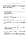
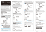
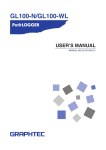
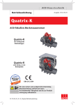
B1FY-6781-01
G R A N P O W E R 5 0 0 0シリーズ
クラスタキット 4(GP5S634)
CLUSTER KIT4(GP5S634)
J
USER’S GUIDE
E
はじめに
このたびは、弊社のクラスタキットをお買い上げいただき、まことにあり
がとうございます。
本キットは GRANPOWER5000 シリーズの PCI 拡張スロットに装着するこ
とによってクラスタシステムを構築するための装置です。
ご使用になる前に本書をよくお読みになり、正しい取り扱いをされますよ
うお願いいたします。
本クラスタキットを搭載したクラスタシステムは、保守要員による現調保
守が必須となっております。詳細は担当営業員までお申しつけください。
1999 年 11 月
当社のドキュメントには「外国為替および外国貿易管理法」に基づく特定技術が
含まれていることがあります。特定技術が含まれている場合は、当該ドキュメン
トを輸出または非居住者に提供するとき、同法に基づく許可が必要となります。
注意
この装置は、情報処理装置等電波障害自主規制協議会(VCCI)の基準に基づ
くクラスA情報技術装置です。この装置を家庭環境で使用すると電波妨害を引き
起こすことがあります。この場合には使用者が適切な対策を講ずるよう要求され
ることがあります。
Adaptecは、Adaptec社の登録商標です。
Microsoft、Windows、Windows NT、MS、MS-DOSは、米国Microsoft Corporationの米
国およびその他の国における登録商標です。
その他の各製品名は、各社の商標、または登録商標です。
その他の各製品は、各社の著作物です。
All Rights Reserved,Copyright© 富士通株式会社1999
梱包物を確認してください
ご使用になる前に、次のものが梱包されていることをお確かめください。
万一足りないものがございましたら、おそれいりますが、担当営業員まで
お申しつけください。
l LAN カード 2 枚
l LAN ドライバ(3.5 インチフロッピーディスク)1 枚
l LAN ケーブル(クロスケーブル)1本
l クラスタ運用支援ツール(3.5 インチフロッピーディスク)1 枚
(Microsoft Cluster Server 運用支援ツール)
l 共有 RAID 装置監視機能(3.5 インチフロッピーディスク)2 枚
l 共有 RAID 装置監視機能をお使いになる前に(マニュアル)1部
l 保証書
l 取扱説明書(本書)
安全上のご注意
ご使用の前に、この「安全上のご注意」とマニュアル類をよくお読みになり、
内容をよくご理解のうえ、正しく製品をご使用ください。
なお、本説明書では安全上の注意点を、以下のマークとともに表示していま
す。
警告
この表示を無視して、誤った取り扱いをすると、人が死亡
する可能性または重傷を負う可能性があることを示してい
ます。
注意
この表示を無視して、誤った取り扱いをすると、人が損害
を負う可能性があること、および物的損害のみが発生する
可能性があることを示しています。
マーク
内容
警告
■ 本製品を改造しないでください。火災・感電の原因と
なります。
■ 近くで雷が発生した時は、サーバ本体の電源コードや
本カードの外部接続コードを抜いてください。そのま
ま使用すると、雷によっては機器破損、火災の原因と
なります。
■ 本カードをサーバ本体に着脱する際には、安全のため
サーバ本体および接続されている機器の電源を切り、
電源プラグをコンセントから抜いた後で行ってくださ
い。電源を入れたままカードの着脱を行うと、装置の
故障・発煙などが起こる可能性があり、また感電の原
因となります。
■ 機器を移動する場合は、必ず機器の外部に接続されて
いるコード類(本製品に接続されているコード類を含
む)をすべてはずしてください。コード類が傷つき火
災・感電の原因となること、機器が落ちたり倒れたり
してケガの原因となることがあります。
■ 製品は精密に作られていますので、高温・低温・多湿・
直射日光など極端な条件での使用・保管は避けてくだ
さい。また、製品を曲げたり、傷つけたり、強いショ
ックを与えたりしないでください、故障・火災の原因
となることがあります。
■ ご使用にならない場合は、静電気防止のため付属のカ
ード袋へ入れて保管してください。
注意
目次
1 クラスタ構成図.................................................................1
2 クラスタキットの装着方法 ................................................2
3 ハードウェアの設定 ..........................................................3
3.1 SCSI カードの設定 ..............................................................................................3
3.1.1 ジャンパーピンの確認 ..................................................................................3
3.1.2 SCSI Select utility での設定 ...........................................................................4
3.2 共有 RAID の設定 .................................................................................................6
3.2.1 設定概要.........................................................................................................6
3.2.2 LU 設定準備 ...................................................................................................6
3.2.3 LU の確認 .......................................................................................................7
3.2.4 LU の削除 .......................................................................................................9
3.2.5 LU の設定 .....................................................................................................12
3.2.6 フォーマット ...............................................................................................15
4 カードのテストについて .................................................17
4.1 MS-DOS のカードテスト ..................................................................................17
4.2 Windows NT のカードテスト ............................................................................18
5 注意事項.........................................................................19
6 Microsoft Cluster Server 運用支援ツール ......................20
6.1 FjClusSwitch コマンド.......................................................................................20
6.2 使用方法 .............................................................................................................22
6.2.1 概要 ..............................................................................................................22
6.2.2 インストール ...............................................................................................22
6.2.3 バッチファイルの作成 ................................................................................23
6.2.4 実行スケジュールの設定と実行 .................................................................24
6.2.5 アンインストール............................................................................................24
6.3 使用上の留意点..................................................................................................25
1 クラスタ構成図
クライアント PC
クライアント PC
HUB
サーバ
サーバ
LAN on Mother
LAN カード
LAN on Mother
クラスタキット4
SCSI カード*
LAN カード
SCSI カード*
共有 RAID*
*: ご使用になるソフトウェアによっては、SCSI カード、共有 RAID を使用しない
場合もあります。
1 クラスタ構成図
1
2 クラスタキットの装着方法
注意
カードを装着する際には安全のため本体の電源を切り、電源コードも電源
コンセントからはずしてください。電源を入れたままカードの装着作業を
行うと装置の故障・発煙などが起こる可能性があり、また感電する危険性
があります。
クラスタキット内の LAN カード、および別売の SCSI カードの取り付け方法
は、サーバ本体に添付の取扱説明書の「内蔵オプションの取り付け」をご参照
ください。
クラスタキット内の LAN カードは、LAN カード同士をクラスタキット添付
の LAN ケーブル(クロスケーブル)で接続してください。
クラスタシステムを運用するためには、本マニュアルに従って LAN カード、
別売の SCSI カード、共有 RAID 装置の設定を必ず行ってください。
2
3 ハードウェアの設定
本キットを使用してクラスタシステムを構築する場合、システムによっては
本キットとは別に SCSI カードと、RAID 装置が必要になります。ここではこ
れらを用いてクラスタシステムを構築する際に設定する項目と方法について
説明します。それぞれの装置に添付されている取扱説明書と併せてご覧くだ
さい。
3.1 SCSI カード(GP5−123)の設定
3.1.1 ジャンパーピンの確認
下の図のジャンパーピン J2,J4 がそれぞれショートされているのを確認
してください。
J4 J2
ショートされている
3 ハードウェアの設定
3
3.1.2 SCSI Select utility での設定
カードをサーバに装着し、サーバの電源を投入します。以下のメッセー
ジが出ている状態で Ctrl キーと A キーを同時に押下して SCSI Select utility
を起動します。
Adaptec AHA-2944Ultra W BIOS v1.25
(c)1996 Adaptec、Inc。All Rights Reserved。
333 Press <Ctrl><A> for SCSISelect(TM )Utility!4 4 4
SCSI Select utility が起動されたら
Configure・View Host Adapter Settings
を選択してください。表1の値に設定します。
4
表1
Basic Host Adapter
※2
Host Adapter SCSI ID
7 or 6
SCSI Parity Checking
Enabled
Host Adapter SCSI Termination
Automatic
Boot Device Configuration
Boot Target ID
0
Boot LUN Number
0
SCSI Device Configuration (0-15)
Initiate Sync Negotiation
Yes(Enabled)
Maximum Sync Transfer Rate ※1
20Mbytes/sec
Enable Disconnection
Yes(Enabled)
Initiate Wide Negotiation
Yes(Enabled)
Send Start Unit SCSI Command
No(Disabled)
Include in BIOS Scan
Yes(Enabled)
Ultra SCSI の時、40MB/sec
Advanced Host Adapter Configuration
Reset SCSI Bus at IC Initialization
Disabled
Host Adapter BIOS
Disabled
Support Removable Disks Under BIOS as Fixed Disks
Boot only
Extended BIOS Translation for DOS Drives > 1 G B y t e
Enabled
Display <Ctrl-A> Message During BIOS Initialization
Enabled
Multiple LUN Support
Disabled
BIOS Support for Bootable CD-ROM
Enabled
BIOS Support for Int13 Extensions
Enabled
Support for Ultra SCSI Speed ※1
Disabled
Ultra SCSI の時、Enabled
※1:Ultra SCSI 時、”Support for Ultra SCSI Speed”を Enabled としてから”Maximum Sync
Transfer Rate”の設定をしてください。
※2:片方を7もう片方を6と設定してください。
3 ハードウェアの設定
5
3.2
共有 RAID(GP-DxSx、GP-DxSxR、GP5DxSxR)の設定
3.2.1 設定概要
クラスタシステムを運用するために保守要員による下記の設定が必須と
なります。
保守要員以外が設定を行った場合、誤操作等によりデータを破壊するこ
とがありますので、必ず保守要員に依頼をしてください。
1.マイクロの版数の確認
2.EEPROM の設定
下記の項目は工場設定値から変更する必要があります。
表2
メニュー項目
備考
TARGET
ID
SPECIAL
CONNECT
DUAL
CONFIG
デュアルコントローラ構成時のみ設定
OPTION
デュアルコントローラ構成時のみ設定
3.サーバの電源との連動設定
3.2.2 LU 設定準備
フロントカバーを開け
ENT
を押します。
<キー操作>
右記表示になるまで
<パネル表示>
▼
を
押してください。
LU CONFIG が表示されたら
ENT
を押してください。
SVP
LU
FUNCTION
CONFIG
注:行き過ぎた場合は、再び「LU CONFIG」
表示が出るまで
を押してください。
▼
LU CONFIG
REFER
6
3.2.3 LU の確認
<キー操作>
▼
<パネル表示>
LU CONFIG
REFER
を押し、右のように表
示されたらENT
を押し
てください。
LU■■(▲▲) C# D#
RAID(GP=*、LV=*)
■■
:LU番号を示します。
▲▲
:ターゲットIDを示します。
C#
:現在当該LUを制御するコントローラ番号を示します。
(ターゲットID未確認の場合は“XX”を表示します)
(C0:コントローラ番号0、C1コントローラ番号1)
D#
:初期設定時にLUを制御していたコントローラを示しま
す。
(C0:コントローラ番号0、C1コントローラ番号1)
GP=*:当該LUが含まれるRAIDグループ番号を示します。
(0、1、2、3のいずれかを表示します)
LV=*:当該LUを構成しているRAIDレベルを示します。
(0,1,5のいずれかを表示します)
▼
を押してください。
LU■■(▲▲) C# D#
START P=*、R=*
P=* :ポート番号を示します。
(0∼4のいずれかを表示します)
R=* :列番号を示します。
(0∼3のいずれかを表示します)
▼
を押してください。
LU■■(▲▲) C# D#
CAPA=**********
当該LUの容量を示します。
3 ハードウェアの設定
7
▼
を押してください。
LU■■(▲▲) C# D#
STAGING=****
当該LUの先読みステージング容量を示
します。
STAGING=128
先読み量として128KB が指示されて
いることを示します。
▼
を押してください。
LU■■(▲▲) C# D#
ST=*********
下記のいずれかを示します。
項番
1
2
3
4
▼
表示
UNFORMAT
NORMAL
DETACHED
REGRESSED
意味
当該 LU は未フォーマット
当該 LU は正常
当該 LU は閉塞
当該 LU は縮退
を押してください。
LU■■(▲▲)
(QUIT)
C#
D#
QUITが表示されたら
ENT
を押してください。
LU CONFIG
REFER
LU 構成情報参照操作が完了したことを
示します。
8
3.2.4 LU の削除
注)本操作を実行するとロジカルユニットが削除されるため、データが
消滅します。
必ずデータのバックアップを行ってから作業を進めてください。
<キー操作>
右記表示になるまで
押してください。
<パネル表示>
▼
▼
を
LU CONFIG
DELETE
LU 削除機能メニュー表示
2行目の表示内容
▼
▲
キーを押して2
行目の表示内容を選択してく
ださい。
ENT
を押してください。
項番 表示項目
機能概要
1 ALL LU
全 LU を削除する。
2 LAST LU■■ 最終 LU を削除する。
(▲▲) LU 番号、ターゲット
ID
3 (QUIT)
直前の(LU 機能選択)
削除する LU が存在しないときは
#NO EFECT と表示されます。
3 ハードウェアの設定
9
(1)全 LU の削除
DEL ALL
(QUIT)
LU?
2行目の表示内容
▼
▲
キーを押して2
行目の表示内容を選択してく
ださい。
ENT
項番 表示項目
1 (QUIT)
2 YES
機能概要
直前の(LU 機能選択)
メニューに戻る。
全 LU を削除する。
を押してください。
DEL ALL LU
EXECUTING
LU 削除処理中。
DEL LU CMP
(QUIT)
しばらくすると上記表示になり、LU
削除処理が完了したことを示します。
QUIT 表示を確認して
ENT
を押してください。
LU CONFIG
DELETE
LU 削除操作が完了したことを示します。
10
(2)最終 LU の削除
DEL LU■■?
(QUIT)
■は LU 番号
2行目の表示内容
▼
▲
キーを押して2
行目の表示内容を選択してく
ださい。
ENT
項番 表示項目
1 (QUIT)
2
YES
機能概要
直前の(LU 機能選択)
メニューに戻る。
最終 LU を削除する。
を押してください。
DEL LU■■
EXECUTING
LU 削除処理中。
DEL LU■■
(QUIT)
CMP
しばらくすると上記表示になり、LU
削除処理が完了したことを示します。
QUIT 表示を確認して
ENT
を押してください。
LU CONFIG
DELETE
LU 削除操作が完了したことを示します。
3 ハードウェアの設定
11
3.2.5 LU の設定
<パネル表示>
右記表示になるまで
▼
▼
を
押してください。
ENT
LU CONFIG
INSTITUTE(CTL0)
LU 追加機能メニュー表示
を押してください。
2 行目は
INSTITUTE(CTL0) 、 INSTITUTE(CTL1)
が表示されますので、装置構成に合わせて
選択してください。
INS LU■■(▲▲)
G=0 ALL CAPA
■ ■:追加する LU 番号を表示します。
(未使用な LU 番号が若番で自動的に表示
されます)
▲ ▲:ターゲット ID を表示します。
▼
2行目は
を押すと下記パターンが
順次表示されます。
項番
1
G=0
12
表示パターン
ALL CAPA
2
*
G=0
C=**********
3
G=1
4
*
G=1
C=**********
5
G=2
6
*
G=2
C=**********
7
G=3 ALL CAPA
8
*
G=3
C=**********
9
(QUIT)
ALL
ALL
CAPA
CAPA
使用目的
RAID グループ0の空き容量すべてを LU とし
て定義します。
RAID グループ0に C=で指定した容量の LU を
定義します。
指定する容量はロジカルブロック数で行います。
RAID グループ 1 の空き容量すべてを LU とし
て定義します。
RAID グループ 1 に C=で指定した容量の LU を
定義します。
指定する容量はロジカルブロック数で行います。
RAID グループ 2 の空き容量すべてを LU とし
て定義します。
RAID グループ 2 に C=で指定した容量の LU を
定義します。
指定する容量はロジカルブロック数で行います。
RAID グループ 3 の空き容量すべてを LU とし
て定義します。
RAID グループ 3 に C=で指定した容量の LU を
定義します。
指定する容量はロジカルブロック数で行います。
ロジカルブロック数の設定方法
G=*
C=**********
ここに入力してください
(a)ロジカルユニットは、全 RAID グループを最大8個まで分割することがで
きます。
(b)各ロジカルユニットに設定するロジルカルブロック数は、RAID レベルに
応じて以下の倍数で設定してください。
RAID0
128
RAID1
128
RAID5
512
(c)各 RAID グループを複数のロジカルユニットに分割する場合、それぞれの
ロジカルユニットのロジカルブロック数の総和は、下記に示す1列当たりロ
ジカルブロック数以下で設定してください。
(d)1列毎のロジカルブロック数を次に示します。
①1列に5台のディスクが搭載されている場合(RAID1 の場合は4台)
GP-D8HD1
GP-D16HD1
GP-D35HD1
2.0GB
4.1GB
8.7GB
RAID0
20,200,960
40,652,160
85,085,440
RAID1
8,080,384
16,260,864
34,034,176
RAID5
16,160,768
32,521,728
68,068,352
②1列にn台のディスクが搭載されている場合(n<5)
・ RAID0
ロジカルブロック数=m × n
・ RAID1
ロジカルブロック数=m × int(n/2)
mは下表を参照してください。
nは2以上
intは切り捨て
容量
m
GP-D8HD1
2.0GB
4,040,192
GP-D16HD1
4.1GB
8,130,432
GP-D35HD1
8.7GB
17,017,088
3 ハードウェアの設定
13
目的の表示パターンが表示された
ら
ENT
を押してください。
(これにより、LU の容量が決定
されます)
H−BLOCK
512B
SIZE
ホストブロック長の指定を行います。
ホストブロック長は通常512B に設
定します。
▼
を押すと“512B”→”CANCEL”
が表示されます。メーカの指定があった
場合にのみ520Bを選択してください。
ENT
を押してください。
ENT
”CANCEL”表示で
を押すと
ホストブロック長の再設定を行うことが
できます。
INS LU
YES
?
LU追加の確認メッセージが表示されます。
▼
ENT
を押してください。
を押すと”CANCEL”が表示され
この状態で ENT
を押すとLUの追
加を中止することができます。
INS LU
?
EXECUTING
LU追加処理中である
ことを示します。
INS LU
(QUIT)
CMP
しばらくすると上記表示になります。
LU追加処理が完了したことを示します。
QUIT 表示を確認して
ENT
を押してください。
LU CONFIG
INSTITUTE
LU追加操作が完了したことを示します。
3.2.2 LUの確認 の手順で、設定したLUの確認を行ってからフォーマット
を行ってください。
14
3.2.6 フォーマット
注)フォーマット済みの LU をフォーマットすると既存のデータが失わ
れてしまうのでご注意ください。
また、LU フォーマットは設定した LU 毎に実行してください。
<キー操作>
右記表示になるまで
押してください。
ENT
<パネル表示>
▼
▼
を
LU CONFIG
FORMAT
を押してください。
FORMAT LU
LU■■(▲▲)C#:****
■■
:LU 番号を表示します。
▲▲
:ターゲット ID を表示します。
C#
:現在当該 LU を制御するコントローラ番号を示します。
(C0:コントローラ番号 0、C1:コントローラ番号 1)
2行目は
▼
を押すと下記パターンが順次表示されます。
****:フォーマット状態として以下の2種類を表示します。
▼
FORM
:フォーマット済み状態
UNFM
:未フォーマット状態
を押すことで次の定義済み LU フォーマット状態を表示
することができます。
フォーマットする LU が表示さ
れたら
ENT
を押してくだ
さい。
FOMT LU
(QUIT)
?
3 ハードウェアの設定
15
▼
▲
キーを押して2
行目の表示内容を選択してく
ださい。
ENT
項目 表示項目
1
(QUIT)
2
YES
機能概要
フォーマットは実行せず
前(LU 選択)画面に戻る。
フォーマットする
を押してください。
FOMT LU
?
EXECUTING
LU フォーマット処理中
であることを示します。
FOMT LU
(QUIT)
CMP
#
しばらくすると上記表示になります。
LU フォーマット処理が完了したことを
示します。
QUIT表示を確認して
ENT
16
を押してください。
FORMAT LU
LU■■(▲▲)C#:****
4 カードのテストについて
添付のフロッピーディスクの診断ソフトウェアを使用すると、本カードのハ
ードウェア、ケーブル配線、またはネットワーク接続に問題がないかを調べ
ることができます。本カードの取付け後に診断テストを実行することをお勧
めします。また、診断結果を利用すれば、トラブルシューティング時に問題
の切り分けをすることもできます。
なお、診断テストを行う場合、本カードの割り込み(IRQ)を他のデバイス
と共有しないで行ってください。
4.1 MS-DOS のカードテスト
■本カード単体でテストする方法
1.サーバを起動した後、LAN ドライバのディスクをドライブに挿入し、
そのドライブに切り換えてから、コマンドプロンプトで次のように入
力します。
DOS/V の場合、chev us で英語 DOS へ切り換えてから実行します。
SETUP
[ENTER]
2.本体に2枚以上の本カードがある場合は、「Board」メニューが表示さ
れます。そのメニューからテストしたいカードを選択します。
3.メイン・メニューから、Test adapter を選択します。
4.さらに、サブメニューから Test adapter を選択すると、カードのテスト
が実行されます。このとき、ケーブルと HUB を接続しておいてくだ
さい。接続していないとケーブルが接続されていないというメッセー
ジが画面に表示されますが、カードのエラーではありません。
■ネットワーク上のレスポンダを使用して本カードをテストする方法
1.本カードを搭載した本体を2台用意し、ケーブル、HUBを接続して
ネットワークを組みます。
※レスポンダとして設定する本体に搭載するLANカードも必ず本説明
書対象のGP5シリーズのLANカードを使用して下さい。
2.[■本カード単体でテストする方法]の1から3までの手順を、それ
ぞれの本体で行います。
3.まず、1台目の本体において、サブメニューから「Set up as responder」
を選択します。
4.テストしたい(もう1台の)本体に戻ります。サブメニューから
Continuous Net work test を選択します。
4 カードのテストについて
17
4.2 Windows NT のカードテスト
コンピュータにカードを装着してから WindowsNT でリスタートし、
WindowsNT の下でコンフィグレーションを行う必要があります。
■アダプタ、ネットワークテスト
このテストを行う場合は、アダプタのデバイスドライバのインストールを
行い、必ずケーブル、HUB を接続しておいてください。
1.コントロール・パネルのネットワーク・アイコンをダブルクリックし
ます。
2.[Intel PROSet]をダブルクリックします。
3.[Diagnostics]のタブを選択し、次に[Run Test]クリックします。
4.診断テストが実行され、アダプタとネットワークテストをします。Fail
の数が 0 であれば、問題ありません。
18
5 注意事項
・ 2 台のサーバは同一モデルで、同一構成(CPU 数、CPU 周波数、メモ
リ容量、ハードディスク容量、ハードディスク数)としてください。
・ 2 台のサーバのメモリ容量は64MB 以上としてください。
・ OS は内蔵ディスクに入れ、BOOT デバイスとしてください。
・共有 RAID 装置へ接続している SCSI コントローラには、光磁気ディス
ク、DAT 等の SCSI 接続外部I/Oは接続禁止です。
・共有 RAID は1つのクラスタシステムに最大2台まで接続可能です。
SCSI のいもづる接続は不可です。SCSI カードは別々に用意してくださ
い。
5 注意事項
19
6 Microsoft Cluster Server 運用支援ツール
本支援ツールは、Microsoft Cluster Server によるクラスタを運用する際
のみ使用します。
クラスタキット 4 を使用したクラスタシステム(Microsoft Cluster Server を
使用したクラスタシステム)を停止する際には、業務グループを、一旦オ
フラインにします。また、起動時は、両ノードの起動を確認した後、必
要な業務グループをオンラインにします。(注)
本支援ツールは、リソースグループのオンライン/オフラインを簡単に
制御するためのコマンドを提供します。
このコマンドを特定時刻に起動するようシステムに登録することでシス
テムの円滑な自動スケジュール運転が実現できます。
注)Microsoft Cluster Server では、リソースグループ(業務グループ)がオンライ
ンのままシステムを停止した場合、先に停止したノードで動作していたリソ
ースグループがもう一方のノードにフェールオーバされ、一時的に再起動さ
れることがあります。
また、起動時には、両ノードが起動完了した時点で、優先所有者およびフ
ェールバックの指定がされている場合、リソースグループがフェールバック
により指定ノードに再配置されます。この際、一旦起動されていた業務が別
ノードに再起動されることがあります。
6.1 FjClusSwitch コマンド
FjClusSwitch コマンドは、クラスタ上で動作するリソースグループの一
括したオンラインおよびオフラインを実現します。本機能は、クラスタ
のスケジュール運用を行う際に使用します。
FjClusSwitch コマンドでは、クラスタのリソースグループをオフライン
のまま起動し、優先所有者として指定されたノードへの配置が正しく行
われた後、実行することにより、資源を一括してオンラインにすること
ができます。
また、運用終了時には、一括してオフラインにすることができます。
20
FjClusSwitch
Microsoft Cluster Server に登録されているリソースグループを一括してオ
ンラインまたはオフラインにします。なお、以下のグループは制御の対
象にはなりません。
− クラスタグループ
− クォーラムリソースの含まれるリソースグループ
コマンド文法
FjClusSwitch /S
FjClusSwitch /E
FjClusSwitch /?
パラメータ
/S
クラスタグループおよびクォーラムリソースの含まれるリソースグルー
プを除いたすべてのリソースグループをオンラインにします。
/E
クラスタグループおよびクォーラムリソースの含まれるリソースグルー
プを除いたすべてのリソースグループをオフラインにします。
/?
使用方法を表示します。
なお、パラメタを省略した場合、使用方法が表示されます。
復帰コード
0:オンラインまたはオフラインの処理が正常に終了しました。
1:すべてのグループまたは一部のグループのオンライン処理またはオフライ
ン処理に失敗しました。
6 Microsoft Cluster Server 運用支援ツール
21
6.2
使用方法
6.2.1 概要
FjClusSwitch コマンドは、UPS および PowerChute Plus によりクラスタの
スケジュール運転を行う際に AT コマンドと組み合わせて使用します。
電源のスケジュールにより各ノードが起動され、各ノードのブートが完
全に終っている時間に FjClusSwitch コマンドが実行されるように AT コ
マンドによるスケジュールを設定します。また、終了時には AT コマン
ドによる FjClusSwitch コマンドが実行され、すべてのリソースグループ
がオフラインになった後に、システムを停止するように電源をスケジュ
ールします。
上記の設定をクラスタを構成する両方のノードに設定することで、何ら
かの理由により、一方のノードが起動されなかった場合でも、業務が開
始できるようにします。
6.2.2 インストール
Microsoft Cluster Server 運用支援ツールでは、インストーラを提供しませ
ん。インストールでは、提供媒体中の FjClusSwitch.exe ファイルをクラス
タを構成する各ノードの任意のフォルダにコピーしてください。
コピーするフォルダの存在するドライブは、NTFS でフォーマットしてお
き、コピー後には、ファイルのセキュリティにより、アドミニストレー
タ権限を持つ利用者のみが使用可能なようにアクセス権を設定すること
を推奨します。
22
6.2.3 バッチファイルの作成
FjClusSwitch コマンドでは、コマンドで何らかのエラーが発生した場合、
標準エラー出力へエラーメッセージを出力します。このため、
FjClusSwitch コマンドを実行するバッチファイルを作成し、バッチファ
イル中で結果をファイルへリダイレクトし、結果を後で確認できるよう
にしておくことを推奨します。
以下に、一括したオンラインを行う場合のバッチファイルの例を示しま
す。
@echo off
SET BinPath=C:¥Tool¥FjClusSupport
SET OutPath=C:¥Tool¥FjClusSupport
DATE /T >%OutPath%¥OnlineOut.LOG
TIME /T >>%OutPath%¥OnlineOut.LOG
%BinPath%¥FjClusSwitch /S 2>>%OutPath%¥OnlineOut.LOG
なお、処理が正常に終了した場合は、メッセージは出力されません。何
らかの異常が発生した場合のみメッセージは出力されます。
FjClusSwitch コマンドと同様、ファイルのセキュリティにより、アドミ
ニストレータ権限を持つ利用者のみが使用可能なようにアクセス権を設
定することを推奨します。
6 Microsoft Cluster Server 運用支援ツール
23
6.2.4 実行スケジュールの設定と実行
AT コマンドによって、実行スケジュールを設定します。AT コマンドの
パラメタには作成したバッチファイルのパスを指定します。
以下に AT コマンドの例を示します。例では、月曜日から金曜日の毎朝、
9時から業務の開始をスケジュールしています。
C:¥>at
一覧にエントリが存在しません。
C:¥>at 09:00 /every:M,T,W,Th,F "c:¥ClusTool¥ClusOnline.bat"
新しいジョブをジョブ ID = 0 で追加しました。
C:¥> at
ステータス ID 日付
時刻
コマンド ライン
----------------------------------------------------------------------------------------------------------0 毎 月曜日 火曜日...午前 09:00
c:¥ClusTool¥ClusOnline.bat
C:¥>
AT コマンドの実行のためには、Schedule サービスが動作している必要
があります。このため、
『コントロールパネル』−『サービス』で Schedule
サービスのプロパティを『自動』に設定し、自動的に起動されるように
してください。
6.2.5 アンインストール
クラスタ運用支援ツールのアンインストールでは、インストール時にコ
ピーしたファイルを削除してください。
24
6.3 使用上の留意点
− オンライン済み/オフライン済みのグループへの対処
FjClusSwitch コマンド実行時に、既にオンライン済み/オンライン処
理中またはオフライン済み/オフライン処理中のグループがあった場合、
その処理は無視されます。FjClusSwitch コマンドは正常にオンライン
またはオフラインへの処理が終了したと見なします。
− オンライン処理中/オフライン処理中のグループ
オンライン処理中のグループのオフラインおよびオフライン処理中
のグループのオンラインを行うことはできません。FjClusSwitch コマ
ンドはエラーを返します。
6 Microsoft Cluster Server 運用支援ツール
25
Preface
Thank you very much for purchasing our cluster kit.
Read this manual carefully before using the cluster kit.
The cluster system in which this cluster kit is mounted must be installed and
maintained by our maintenance engineer.
Ask the sales person in charge for details.
Adaptec is a registered trademark of Adaptec Inc.
Microsoft, Windows, MS, and MS-DOS are trademarks of Microsoft Corp. of the United
States, registered in the United States and other countries.
Other product names are trademarks or registered trademarks of their respective owners.
Other products are copyrights of their respective owners.
All Rights Reserved,Copyright © FUJITSU LIMITED 1999
Check the kit contents.
Before using the cluster kit, verify that it contains each of the parts listed below.
If any part is missing, instruct the sales person in charge to provide a
replacement.
•
LAN cards: 2
•
LAN driver (3.5-inch floppy disk): 1
•
LAN cable (cross cable): 1
•
Cluster operation support tool (3.5-inch floppy disk):
Cluster Server operation support tool)
•
User's Guide (this manual)
1 (Microsoft
Safety Precautions
Before using the card, carefully read these Notes on Use and the related manual,
thoroughly understand the information contained in the manual, and use the
product correctly. This document uses the following two safety categories and
their associated icons:
WARNING
Denotes that ignoring information or incorrect use in
CAUTION
Denotes that ignoring information or incorrect use in
this category may result in personal injury or damage
this category may result in death or serious personal
injury.
to property.
Icon
Description
WARNING
■ Do not modify this product. Doing so might
cause fire or electric shock.
■ If lightning occurs near your home, unplug the
power cord of the SERVER or the external
power cord of the card. Using this product
during an electrical storm may result in
equipment damage or fire.
■ To ensure safety, before installing or removing
the card, turn off the power to the SERVER and
peripheral equipment, then unplug the power
cord from the power outlet. Installing or
removing the card while the power is on may
cause electric shock, equipment malfunction, or
smoke.
■ When moving equipment, disconnect all
external cables attached to the equipment
(including cables connected to this product).
Failure to do so could damage the cords,
resulting in fire or electric shock, or could cause
the equipment to topple, resulting in injury.
CAUTION
■ Since this is a precision product, do not use or
store the product under extreme conditions such
as excessively high or low temperatures, high
humidity, or in direct sunlight. Do not bend or
damage the product or subject it to extreme
shock. Doing so may cause malfunction or fire.
■ Store the card in the bag in which it was
packaged to protect it from static electricity
while not in use.
Contents
1 Cluster Configuration..........................................................1
2 Mounting the Cluster Kit .....................................................2
3 Setting the Hardware..........................................................3
3.1 Setting the SCSI Card (GP5-123)......................................................................3
3.1.1 Checking the jumper pins ...........................................................................3
3.1.2 Using the SCSI Select utility for setting .....................................................4
4 LAN Cards.........................................................................6
5 Notes ................................................................................7
6 Microsoft Cluster Server Operation Support Tool..................8
6.1 FjClusSwitch Command .....................................................................................8
6.2 Usage ................................................................................................................10
6.2.1 Overview ....................................................................................................10
6.2.2 Installation..................................................................................................11
6.2.3 Creating a batch file ..................................................................................11
6.2.4 Setting the execution schedule and executing the schedule..................12
6.2.5 Uninstalling the cluster..............................................................................12
6.3 Notes on Use ....................................................................................................13
1 Cluster Configuration
Client personal
computer
Server
Client personal
computer
HUB
LAN on Mother
LAN card
Server
LAN on Mother
Cluster kit 4
SCSI card*
LAN card
SCSI card*
Shared RAID*
*: Some cluster software do not require SCSI card and Shared RAID.
1 Cluster Configuration
1
2 Mounting the Cluster Kit
CAUTION
•
Before mounting the cards, be sure to turn off the main device power and
disconnect the power cable from the power outlet. If the cards are mounted
with the power turned on, the device may fail and/or generate smoke.
Additionally, the user may suffer an electric shock.
For information on how to mount the LAN cards in the cluster kit and the optional
SCSI cards, refer to "Mounting the built-in option" in the user's guide provided with
the server.
Connect the LAN cards in the cluster kit with the LAN cable (cross cable) in the
cluster kit.
When using the cluster system, be sure to set the LAN cards, optional SCSI cards,
and shared RAID as described in this manual.
2
3 Setting the Hardware
When using this kit to construct a cluster system, the SCSI cards and Shared RAID
will be required separately. This chapter describes the items to be set when
constructing the cluster system and how to set them. Read this chapter together
with the user's guides for each of the devices.
3.1
Setting the SCSI Card (GP5-123)
3.1.1 Checking the jumper pins
Ensure that jumper pins J2 and J4 shown in the figure below are connected.
Connected
3 Setting the Hardware
3
3.1.2 Using the SCSI Select utility for setting
Mount the cards in the server, and turn on the server power. To activate the SCSI
Select utility, press the Ctrl and A keys together when the following message is
displayed:
Adaptec AHA-2944Ultra W BIOS v1.25
(c) 1996 Adaptec, Inc. All Rights Reserved.
333Press <Ctrl> <A> for SCSI Select ™ Utility!444
When the SCSI Select utility is activated, select Configure-View Host Adapter
Settings. Set the values listed in Table 1.
4
Table 1 Adapter setting
Basic Host Adapter
Host Adapter SCSI ID
7 or 6
SCSI Parity Checking
Enabled
*2
Host Adapter SCSI Termination
Automatic
Boot Device Configuration
Boot Target ID
Boot LUN Number
0
0
SCSI Device Configuration (0-15)
Initiate Sync Negotiation
Yes (Enabled)
Maximum Sync Transfer Rate *1
20Mbytes/sec
Enable Disconnection
Yes (Enabled)
Initiate Wide Negotiation
Yes (Enabled)
Send Start Unit SCSI Command
No (Disabled)
Include in BIOS Scan
Yes (Enabled)
Advanced Host Adapter Configuration
Reset SCSI Bus at IC Initialization
Disabled
Host Adapter BIOS
Disabled
Support Removable Disks Under BIOS as Fixed Disks
Boot only
Extended BIOS Translation for DOS Drives > 1 Gbyte
Enabled
Display<Ctrl-A> Message During BIOS Initialization
Enabled
Multiple LUN Support
Disabled
BIOS Support for Bootable CD-ROM
Enabled
BIOS Support for Int 13 Extensions
Enabled
Support for Ultra SCSI Speed *1
Disabled
40 MB/s for Ultra SCSI
Enabled for Ultra SCSI
*1: When Ultra SCSI is used, set "Support for Ultra SCSI Speed" to Enabled, then set
"Maximum Sync Transfer Rate".
*2: Set one SCSI ID to 7 and the other to 6.
3 Setting the Hardware
5
4 LAN Cards
For details of the LAN cards, read the README file as follows:
•
Activate the server. Then, insert the LAN driver disk into a drive and
designate that drive the active drive. Then, enter the following character
string at the command prompt:
A:>setup /readme
6
5 Notes
•
The two servers must be the same model with identical configurations (number
of CPUs, CPU frequency, memory capacity, hard disk capacity, and number of
hard disks).
•
The memory capacity of each server must be 64 megabytes or more.
•
Install the OS in the built-in disk to make it a boot device.
•
An external I-O device connected to the SCSI such as a magneto-optic disk or
DAT cannot be connected to the SCSI controller connected to the Shared
RAID.
•
Up to two Shared RAIDs can be connected to the cluster system.
cannot be daisy chained. Prepare the SCSI cards individually.
5 Notes
SCSIs
7
6 Microsoft Cluster Server Operation Support Tool
Use this support tool only when using Microsoft Cluster Server to operate the cluster.
To stop the cluster system using cluster kit 4 (cluster system using Microsoft Cluster
Server), temporarily set the resource groups to offline mode. To activate this cluster
system, verify that both nodes have been activated, then set the required job group to
online mode. (*1)
This support tool provides commands for simple control of online and offline modes
of resource groups.
Smooth automatic scheduled operation of the system is enabled by registering these
commands in the system so that they are activated at specific times.
*1: When the Microsoft Cluster Server is operated, the system may be stopped while
the resource group (job group) is in online mode. In this case, the resource
group that has been operating in the first stopped node may fail over to the other
node and temporarily be reactivated.
When the system is activated, if preferred owner and fail-back are specified
when activation of both nodes terminates, the resource group is reallocated to
the specified node by fail-back. At this time, a job that has been activated in
one node may be reactivated in the other node.
6.1
FjClusSwitch Command
The FjClusSwitch command enables batched online or offline control of resource
groups operating in the cluster. Use this function for scheduled operation of the
cluster.
By executing the FjClusSwitch command after an offline resource group in the
cluster is activated and allocated to the node specified as a preferred owner, all
resources can be set to online mode together.
When the operation ends, the resources can be set to offline mode together.
8
FjClusSwitch
Sets all resource groups registered in Microsoft Cluster Server to online or offline
mode together. However, the FjClusSwitch command does not control the
following groups:
•
Cluster group
•
Resource group containing quorum resource
Command syntax
FjClusSwitch /S
FjClusSwitch /E
FjClusSwitch /?
Parameters
/S
Set all resource groups to online except for a cluster group or resource group
containing quorum resource.
/E
Set all resource groups to offline mode except for a cluster group or resource
group containing quorum resource.
/?
Displays the usage.
If the parameters are omitted, the usage is displayed.
Return codes
0: Online or offline processing terminated normally.
1: Online or offline processing of all or some groups failed.
6 Microsoft Cluster Server Operation Support Tool
9
6.2
Usage
6.2.1 Overview
Use the FjClusSwitch command in combination with the AT command to
perform scheduled operation of the cluster by using UPS and PowerChute Plus.
Each node is activated according to the power supply schedule. The schedule is
set by the AT command so that the FjClusSwitch command is executed when
booting of all nodes has ended. The AT command executes the FjClusSwitch
command to set all resource groups to offline before each node is terminated
according to the power supply schedule .
The above settings in both nodes of the cluster enable the job to be started even if
one node is not activated.
10
6.2.2 Installation
The Microsoft Cluster Server operation support tool does not provide an installer.
To install, copy the FjClusSwitch.exe file in the provided disk to an arbitrary
folder of each node of the cluster.
It is recommended to format the drive with NTFS that contains the folder to copy,
and to set execute permission only for the users with administrator permission by
using the file security after the copying process is performed.
6.2.3 Creating a batch file
If an error occurs in the FjClusSwitch command, the command outputs an error
message to the standard error output. It is recommended that a batch file for
executing the FjClusSwitch command be created so that a command execution
result can be checked later by redirecting the result in the batch file.
The figures below show examples of batch files for batched online processing.
@echo off
SET BinPath=C:\Tool\FjClusSupport
SET OutPath=C:\Tool\FjClusSupport
DATE /T >%OutPath%/OnlineOut.LOG
TIME /T >>%OutPath%/OnlineOut.LOG
%BinPath%\FjClusSwitch /S 2>>%OutPath %\OnlineOut.LOG
When processing terminates normally, no message is output.
output only when an abnormality is detected.
A message is
It is recommended that the access authority be set so that file security allows only
users with the administrator authority to use the file in the same way as when the
FjClusSwitch command is used.
6 Microsoft Cluster Server Operation Support Tool
11
6.2.4 Setting the execution schedule and executing the schedule
Use the AT command to set the execution schedule. Specify the path of the
created batch file in the AT command parameter.
The figure below shows an example of the AT command. In this example, job
start is scheduled at nine o'clock every morning from Monday to Friday.
C: \>at
There are no entries in the list.
C: \>at 09:00 /every:M, T, W, Th, F “c:\ClusTool\ClusOnline.bat”
Added a new job with job ID = 0.
C:\> at
Status ID
0
Date
Time
Command line
Each M T W Th F
9:00 AM
c:\ClusTool\ClusOnline.bat
C:\>
To execute the AT command, the Schedule service must be operating. Set the
property of the Schedule service to "Automatic " in "Control Panel" - "Services"
for automatic activation.
6.2.5 Uninstalling the cluster
When uninstalling the cluster operation support tool, delete the file copied at
installation.
12
6.3
Notes on Use
- Procedure for groups that are already set online/offline
The procedure is bypassed when groups have already been set to
online/offline or when setting to online/offline while FjClusSwitch command
is executing. The normal online and offline procedure is supposed to be
completed from the FjClusSwitch command.
- Procedure for groups including the resource waiting to go online/offline
Setting the group to offline and the resources that are waiting to go online
cannot be executed, and setting the group to online and the resources waiting
to go offline cannot be executed, therefore the FjClusSwitch command
returns an error as a result.
6 Microsoft Cluster Server Operation Support Tool
13
クラスタキット 4(GP5S634)
CLUSTER KIT4(GP5S634)
取扱説明書
USER’S GUIDE
B1FY-6781-01-00
発 行 日 1999年11月
Publication date : November 1999
発行責任 富 士 通 株 式 会 社
Publisher : Fujitsu Limited
Printed in Japan
●本書の内容は、改善のため事前連絡なしに変更することがあります。
●本書に記載されたデータの使用に起因する第三者の特許権およびその他の権
利の侵害については、当社はその責を負いません。
●無断転載を禁じます。
●落丁、乱丁本はお取り替えいたします。
●Information provided in this document is subject to change without prior notice.
●Fujitsu does not assume any liability for infringement of third party patents and any
other rights caused by abuse of information provided in this document.
●Transcription without prior permission is prohibited.
●Any manual which has missing pages or which is incorrectly collated will be
replaced.
ア 9910-1