1
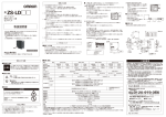
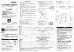
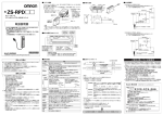
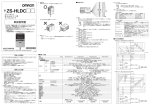
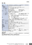
■輸出貿易管理令について
形ZS-LD35AFは海外為替および外国貿易管理法の規定により、輸出許可取
得対象貨物(または技術)
に該当します。
日本国外に持ち出す際には、
日本国政府
の輸出許可申請等、必要な手続きをお取りください。
レーザ安全について
インシュロック
(2)米国で使用する場合
本製品は、米国のレーザ規制FDA
(Food and Drug Administration の規制)
を受
けます。
形ZS-LD35AF/LD35AFTはCDRH
(Center for Devices and Radiological
Health)
に届け出をしていないため、米国へ輸出することはできません。
■外形寸法
(単位:mm)
形ZS-LD35AF/LD35AFT
60
5- C1
3- C1
30
35
45
4-φ4.5取付穴
4-φ9深ザグリ深さ4
10
投光軸
(3)米国を除く諸外国で使用する場合
・国内および米国以外の地域については、警告説明ラベルを付属品の英文ラベルに
貼替えてください。
・ヨーロッパでの使用については、EN60825があり、
規定が異なります。
本製品はEN60825-1
(IEC60825-1)
に定めるクラス2に分類されます。
投光部
C11.5
φ4
受光軸
受光部
7.5
45.5
42
30
70
65
ビニル絶縁丸型コードφ6.2
長さ 0.5m
-M
(25)
φ4
置
位
穴
30.1
4
50±0.1
* 2 7 4 8 4 8 1 - 0 A *
4
C13
42
・ 形ZS-LD35AF/LD35AFTは可視光レーザを放射しています。直接見つめないでください。
レーザビームの光路を終端するようにご使用ください。
終端材は反射の少ないつや消し塗装面が最適です。
光路に鏡面反射体がある場合は、反射光路に対してビームを閉じこめるようにしてくださ
い。解放して使用しなければならない場合、光路は目の高さを避けるようにしてください。
レンジ
表示灯
3- C1
測定中心
■取扱い上の注意
© OMRON Corporation 2007 All Rights Reserved.
フェライトコア
※取付けによりラベルが隠れる場合は付属品の和文ラベルを見える位置に
貼ってください。
90゜
*貴社担当オムロン営業員にお問い合わせください。
フェライトコア
27.9
このたびは、本製品をお買い上げいただきまして、
まことにありがとうございま
す。ご使用に際しては、次の内容をお守りください。
・電気の知識を有する専門家が扱ってください。
・この取扱説明書をよくお読みになり、十分にご理解のうえ、正しくご使用く
ださい。
・この取扱説明書はいつでも参照できるように大切に保管ください。
145
取扱説明書
レーザに関するラベル表示
センサヘッド側面に下図のラベルが貼られています。
8.5
スマートセンサ 形ZS-LDC□□用
センサヘッド
センサヘッドのケーブルの両端に、
フェライ
トコア
(センサヘッドの付属品)
を装着してください。
フェライ
トコアがずれる場合は、付属のインシュロックにより固定してください。
50
ZS-LD35AF/LD35AFT
1. 下記の設置場所では使用しないでください。
・ 強い外乱光(レーザ光、
アーク溶接光など)
や強い電磁界のある場所
・ センサヘッド前面のフイルタに塵埃、油滴、結露が付着する恐れのある場所
・ 腐食性ガスのある場所
・ 本体に直接振動や衝撃が伝わる場所
2. 取付けの前にご確認ください。
・ 対象物の材質・形状によって測定できない場合や精度がでない場合があります。
(透明体、反射率の極端に小さな部材、
スポット径よりも小さな対象物、曲率の大きな対
象物、大きく傾斜した対象物など)
3. 配線について
・ センサヘッド・センサコントローラ間のコードは、高圧線、動力線との接近を避けて配線し
てください。同一配線あるいは同一ダクトにすると誘導を受け、誤動作あるいは破損の
原因になることがあります。
・ センサヘッドの着脱は、必ずセンサコントローラの電源を切った状態で行ってください。電
源ONのまま行うと故障の原因になります。
4. 清掃について
・ シンナー、ベンゼン、
アセトン、灯油類はセンサヘッド表面を溶かしますので、避けてくださ
い。
・ 塵埃の除去にはカメラレンズ用ブロアブラシで吹き飛ばしてください。
・ 取れにくい汚れには柔らかい布にアルコールを少量含ませて、
ていねいに拭き取ってく
ださい。
5. 互換性について
・ センサヘッドとセンサコントローラは互換性があり、別々にお求めいただいてもご使用でき
ます。
■フェライトコアの装着
国内で使用される場合、海外で使用される場合にわけて説明します。
(1)国内で使用する場合
JIS C6802規格で、
レーザ製品のクラスに応じて使用者が行わなければならない
安全予防対策が規定されています。
形ZS-LD35AF/LD35AFTは、本規格に定めるクラス2に分類されます。
65
形
■レーザ機器に関しては使用される国によってレーザ安全対策が規定されています。
65
使用上の注意
30±0.1
コネクタ
基準面
取付穴加工寸法
安全上のご注意
●警告表示の意味
警告
正しい取扱いをしなければ、この危険のために、軽傷・中程度の
傷害を負ったり、万一の場合には重症や死亡にいたる恐れがあ
ります。また、同様に重大な物的損害をもたらす恐れがあります。
●図記号の説明
■定格/性能
●レーザ光線
レーザ光線の危険の可能性を注意する通告に用いる。
LED表示灯
●警告表示
警告
レーザ光を見つづけると視力障害を起こします。
決してビームをのぞき込まないでください。
分解すると、
レーザ光がもれ出し視力障害を起こす
恐れがあります。
分解しないでください。
安全上の要点
以下に示すような項目は安全を確保する上で必要なことですので必ず守ってください。
1. 引火性、爆発性ガスの環境では使用しないでください。
2. この製品は分解したり、
修理、改造をしないでください。
3. ロック機構のあるものは必ずロックしていることを確認してからご使用ください。
4. 廃棄するときは、産業廃棄物として処理してください。
形式
NEAR灯
●分解禁止
機器を分解することで感電などの障害が起こる可能性
がある場合の禁止通告に用いる。
ご使用に際してのご承諾事項
項目
光学方式
測定中心距離
測定範囲
光源
ビーム径(*1)
リニアリティ(*2)
分解能
(*3)
温度特性
(*4)
サンプリング周期
(*5)
使用周囲照度
周囲温度
周囲湿度
絶縁抵抗
耐電圧
保護構造
振動
(耐久)
衝撃
(耐久)
コード長
材質
質量
付属品
FAR灯
形ZS-LD35AF/LD35AFT
正反射
35mm
±1.5mm
可視半導体レーザ
(波長650nm、1mW以下、
JISクラス2)
約60×900μm
±0.1%F.S.
0.8μm
±0.04%F.S./℃
110μs
測定中心距離付近、
および測定範囲内の測定中心距離より近側で点灯
測定範囲外、
または受光量過不足の場合、
フラッシング
測定中心距離付近、
および測定範囲内の測定中心距離より遠側で点灯
測定範囲外、
または受光量過不足の場合、
フラッシング
受光面照度3000 lx 以下(白熱ランプ)
動作時:0 to +50℃, 保存時:−15 to +60℃
(ただし、
結露・氷結しないこと)
動作時・保存時:35% to 85% RH(ただし、結露しないこと)
20MΩ
(DC500Vメガにて)
AC1000V 50/60 Hz 1 min.
IP40
10 ∼150 Hz,(片振幅0.35mm)X,Y,Z 各方向 80min
150m/s2, 6方向 各3回(上下、左右、前後)
0.5m
ケース:アルミ 全面カバー:ガラス
約750 g
レーザ安全説明ラベル
(JIS・EN 各1枚)
, フェアライトコア
(2個)
, インシュロック
(2個)
, 取扱説明書
*1.測定中心距離の値(代表値)で、
中心光強度の1/e2(13.5%)で定義しています。
定義域外にも漏れ光があり、
ワーク周囲の光反射率がワークに比べて高い状況では、
影響の出る場合があります。
*2.測定値における理想直線に対する誤差。
ワークはガラス。
ワークによって直線性が変わることがあります。
*3.平均回数128回、
高精度モードに設定した場合の測定中心距離における変位出力の「ピーク to ピーク」の変位換算値。
ワークはガラス。
輸出貿易管理令非該当形式 ZS-LD35AFTの最小分解能は平均回数によらず、
0.
25μmです。
*4.センサヘッドとワークの間をアルミ治具で固定した場合の測定中心距離における温度特性の代表値。
*5.高速モード設定時。
①安全を確保する目的で直接的または間接的に人体を検出する用途に、
本製品を使用し
ないでください。同用途には、
当社センサカタログに掲載している安全センサをご使用く
ださい。
②下記用途に使用される場合、
当社営業担当者までご相談のうえ仕様書などによりご確
認いただくとともに、
定格・性能に対し余裕を持った使い方や、
万一故障があっても危険
を最小にする安全回路などの安全対策を講じてください。
a)屋外の用途、
潜在的な化学的汚染あるいは電気的妨害を被る用途
またはカタログ、
取扱説明書等に記載のない条件や環境での使用
b)原子力制御設備、
焼却設備、
鉄道・航空・車両設備、
医用機械、
娯楽機械、
安全装置、
および行政機関や個別業界の規制に従う設備
c)人命や財産に危険が及びうるシステム・機械・装置
d)ガス、
水道、
電気の供給システムや24時間連続運転システムなどの
高い信頼性が必要な設備
e)その他、
上記 a) ∼ d) に準ずる、
高度な安全性が必要とされる用途
*上記は適合用途の条件の一部です。当社のベスト、
総合カタログ・データシート等最新版
のカタログ、
マニュアルに記載の保証・免責事項の内容をよく読んでご使用ください。
インダストリアルオートメーションビジネスカンパニー ●お問い合わせ先
カスタマサポートセンタ
フリーコール
01 2 0 - 9 19 - 0 6 6
携帯電話・PHSなどではご利用いただけませんので、
その場合は下記電話番号へおかけください。
電話
055-982-5015 (通話料がかかります)
〔技術のお問い合わせ時間〕
■営業時間:8:00∼21:00
■営 業 日:365日
■上記フリ−コ−ル以外のセンシング機器の技術窓口:
電話
055-982-5002
(通話料がかかります)
〔営業のお問い合わせ時間〕
■営業時間:9:00∼12:00/13:00∼17:30 (土・日・祝祭日は休業)
■営 業 日:土・日・祝祭日/春期・夏期・年末年始休暇を除く
●FAXによるお問い合わせは下記をご利用ください。
カスタマサポートセンタ お客様相談室 FAX 055-982-5051
●その他のお問い合わせ先
納期・価格・修理・サンプル・仕様書は貴社のお取引先、
または貴社担当オムロン営業員にご相談ください。
q 2 0 0 9 年 1 0月
Thank you for selecting OMRON product. This sheet primarily
describes precautions required in installing and operating the product.
Before operating the product, read the sheet thoroughly to acquire
sufficient knowledge of the product. For your convenience, keep the
sheet at your disposal.
■Export and Trade Control Laws
The ZS-LD35AF is classed as a commodity (or technology) requiring
acquisition of export permission in accordance with foreign exchange and
overseas trade control laws. When the ZS-LD35AF is to be taken outside
of Japan, adopt the required procedures such as application for export
permission by the Japanese government.
Insure Lock
Ferrite core
Ferrite core
■Dimensions
(unit: mm)
ZS-LD35AF/LD35AFT
5- C1
60
3- C1
30
35
45
4-4.5 Dia. MOUNTING HOLES
4-9 Dia. SPOT FACING DEPTH 4
10
LIGHTENING
AXIS
C11.5
LIGHTENING
PART
Dia.4
90゜
* Contact your OMRON representative.
(2) Using in a country other than U.S.
・ For countries other than Japan and U.S., warning labels must be replaced by
English ones (supplied with the product).
・ EN60825 is provided for products used in Europe, and the content of this standard
differs.
The ZS-LD35AF/LD35AFT is categorized as a Class 2 device as stipulated in
EN60825-1 (IEC60825-1).
3-C1
CENTER
RECEVING
PART
7.5
42
65
© OMRON Corporation 2007 All Rights Reserved.
PRECAUTIONS ON SAFETY
●Meanings of Signal Words
Indicates a potentially hazardous situation which, if
not avoided, will result in minor or moderate injury,
WARNING or may result in serious injury or death. Additionally,
there may be significant property damage.
●Meaning of Alert Symbols
Indicates the possibility of laser radiation.
Indicates prohibition when there is a risk of minor
injury from electrical shock or other source if the
product is disassembled.
●Alert Statements in this Sheet
WARNING
Never look into the laser beam.
Doing so continuously will result in visual
impairment.
Do not disassemble the product.
Doing so may cause the laser beam to leak,
resulting in the danger of visual impairment.
PRECAUTIONS FOR SAFE USE
Please observe the following precautions for safe use of the product:
1. Do not use the product in environments where it can be exposed to
inflammable/explosive gas.
2. Do not disassemble, repair or modify this product.
3. Be sure to make sure that locking mechanisms are locked before use.
4. Dispose of this product as industrial waste.
4
(25)
4
a.
Di
LE
HO
O
TI
SI
PO
30 ±0.1
MOUNTING SCREW HOLES
■Specifications
VINYL INSULATED ROUND CORD Dia.6.2
LENGTH 0.5m
STANDARD
SURFACE
CONNECTOR
Suitability for Use
Item
Optical system
Measuring Center distance
Measuring range
Light source
Beam diameter (*1)
Linearity (*2)
Resolution (*3)
Temperature characteristic (*4)
Sampling cycle (*5)
NEAR indicator
Indicators
42
30
70
N
M
450 0.1
・ The ZS-LD35AF/LD35AFT emits a visible laser beam. Do not stare directly into the laser.
Make sure that the laser beam path is terminated.
A non-reflective matte painted surface is ideal at the end of the laser beam path.
If specular objects are present in the laser beam path, make sure that they are prevented
from reflecting the laser beam. When used without an enclosure, make sure the laser
path from eye level is avoided.
45.5
30.1
■Handling Precautions
4
8.5
RECEIVING
AXIS
LASER SAFETY
RANGE
INDICATOR
C13
27.9
INSTRUCTION SHEET
Attach the ferrite core (provided with the Sensor Head) to both ends of the Sensor
Head cable.
If the ferrite core comes loose from the cable, fasten the ferrite core in place with the
Insure Lock (supplied).
145
Sensor Head for Smart Sensor ZS-LDC□□
(1) Using in U.S.
When using devices in which this product is installed in U.S., the devices are
subjected to the U.S. FDA (Food and Drug Administration) laser regulations.
The ZS-LD35AF/LD35AFT isn’t registered to CDRH
(Center for Devices and Radiological Health)
Therefore, the ZS-LD35AF/LD35AFT cannot be exported to the United States.
■Attaching the ferrite core
50
ZS-LD35AF/LD35AFT
country of use.The following describes the method of use according to where the
product is exported.
65
Model
1. Do not install the product in locations subjected to the following conditions:
・ Reflection of intense light (such as other laser beams or electric arc-welding
machines)
・ Presence of dust, oil droplets or spray on the filter on the front of the Sensor
Head
・ Presence of corrosive or flammable gases
・ Direct vibration or shock
2. Pre-installation Checks
・ The product cannot accurately measure the following types of objects:
(transparent objects, objects having an extremely low reflection factor, objects
smaller than the spot diameter, objects with a large curvature, excessively
inclined objects, etc.)
3. Wiring
・ Avoid wiring the cable between the Sensor Head and Sensor Controller
including this product near high voltage lines and power lines.
Wiring them together or placing them in the same duct may cause induction,
resulting in malfunction or damage.
・ Before connecting/disconnecting the Sensor Head, make sure that the Smart
Sensor is turned OFF. The Smart Sensor may break down if the Sensor Head is
connected or disconnected while the power is ON.
4. Cleaning
・ Do not use paint thinner, benzene, acetone or kerosene to clean the Sensor
Head. Doing so will melt the surface of the Sensor Head.
・ To remove dust particles, use a blower brush.
・ To remove stubborn dirt, wipe gently with a soft cloth moistened with a small
amount of alcohol.
5. Compatibility
・ The Sensor Head is compatible with the Sensor Controller, and can be used if
purchased separately.
■ Various safety standards regarding laser devices are stipulated depending on the
65
PRECAUTIONS FOR CORRECT USE
FAR indicator
Operating ambient illumination
Ambient temperature
Ambient humidity
Insulation resistance
Dielectric strength(destructive)
Degree of protection
Vibration resistance(destructive)
Shock resistance(destruction)
Cable length
Materials
Weight
Accessories
Model
ZS-LD35AF/LD35AFT
Regular reflection
35mm
±1.5mm
Visible semiconductor laser
(wavelength 650nm,
1mW max.,
Class 2)
Approx. 60×900μm
±0.1%F.S.
0.8μm
±0.04%F.S./℃
110μs
Lit near measuring center distance, and nearer than measuring center distance inside the
measuring range Blinks when the measurement target is outside of the measuring range or when
the received light amount is insufficient
Lit near measuring center distance, and further than measuring center distance inside the
measuring range Blinks when the measurement target is outside of the measuring range or when
the received light amount is insufficient
Illumination on received light surface 3000 lx or less (incandescent light)
Operating:0 to +50℃, Storage: -15 to +60℃ (with no icing or condensation)
Operating and storage: 35% to 85% RH (with no condensation)
20MΩ
(by 500V megger)
AC1000V 50/60 Hz 1 min.
IP40
10 to 150 Hz, 0.35-mm half amplitude 80 min each in X,Y and Z directions
150m/s2, for 3 times each in X,Y and Z directions
0.5m
Case:aluminum, front cover: glass
Approx. 750 g
Laser label(1 each for JIS/EN), Ferrite core(2 pcs), Insure Lock(2 pcs), Instrution sheet
THE PRODUCTS CONTAINED IN THIS SHEET ARE NOT SAFETY RATED.
THEY ARE NOT DESIGNED OR RATED FOR ENSURING SAFETY OF
PERSONS, AND SHOULD NOT BE RELIED UPON AS A SAFETY
COMPONENT OR PROTECTIVE DEVICE FOR SUCH PURPOSES.
Please refer to separate catalogs for OMRON's safety rated products.
OMRON shall not be responsible for conformity with any standards, codes, or
regulations that apply to the combination of the products in the customer's
application or use of the product.
Take all necessary steps to determine the suitability of the product for the
systems, machines, and equipment with which it will be used.
Know and observe all prohibitions of use applicable to this product.
NEVER USE THE PRODUCTS FOR AN APPLICATION INVOLVING
SERIOUS RISK TO LIFE OR PROPERTY WITHOUT ENSURING THAT THE
SYSTEM AS A WHOLE HAS BEEN DESIGNED TO ADDRESS THE RISKS,
AND THAT THE OMRON PRODUCT IS PROPERLY RATED AND
INSTALLED FOR THE INTENDED USE WITHIN THE OVERALL
EQUIPMENT OR SYSTEM.
See also Product catalog for Warranty and Limitation of Liability.
EUROPE
OMRON EUROPE B.V. Sensor Business Unit
Carl-Benz Str.4, D-71154 Nufringen Germany
Phone:49-7032-811-0 Fax: 49-7032-811-199
NORTH AMERICA
OMRON ELECTRONICS LLC
One Commerce Drive Schaumburg,IL 60173-5302 U.S.A.
Phone:1-847-843-7900 Fax : 1-847-843-7787
ASIA-PACIFIC
OMRON ASIA PACIFIC PTE. LTD.
No. 438A Alexandra Road #05-05-08(Lobby 2),
Alexandra Technopark, Singapore 119967
Phone : 65-6835-3011 Fax :65-6835-2711
CHINA
OMRON(CHINA) CO., LTD.
Room 2211, Bank of China Tower,
200 Yin Cheng Zhong Road,
PuDong New Area, Shanghai, 200120, China
Phone : 86-21-5037-2222 Fax :86-21-5037-2200
*1 Defined as 1/e2 (13.5 %) of the center optical intensity in the measurement center distance (typical value). The beam diameter is sometimes influenced by the ambient conditions of the workpiece such as
leaked light from the main beam.
*2 This is the error on the measured value with respect to an ideal straight line. The standard workpiece is glass. Linearity may change according to the workpiece.
*3 This is the "peak-to-peak" displacement conversion value of the displacement output in the measuring center distance when the number of samples to average is set to 128, and the measuring mode is set to
high-resolution mode. The standard workpiece is glass. The minimum resolution of ZS-LD35AFT is 0.25μm regardless of average count setting.
*4 This is the typical value obtained in the measuring center distance when the sensor and workpiece are fixed by an aluminum tool.
*5 This value is obtained when the measuring mode is set to the high speed mode.
OMRON Corporation
o
O C T, 2 0 0 9