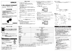
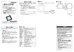
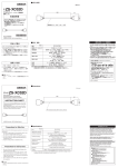
1
■輸出貿易管理令について
形ZS-HLDS2は海外為替および外国貿易管理法の規定により、輸出許可
取得対象貨物(または技術)
に該当します。
日本国外に持ち出す際には、
日
本国政府の輸出許可申請等、必要な手続きをお取りください。
*貴社担当オムロン営業員にお問い合わせください。
※取付けによりラベルが隠れる場合は付属品の
和文ラベルを見える位置に貼ってください。
フェライトコア
(2) 米国で使用する場合
を受けます。
本製品は、米国のレーザ規制FDA(Food and Drug Administration の規制)
FDAラベル3種類をセンサ本体に貼ってください。
・ラベルを貼る位置
形ZS-HLDS2/HLDS2T
26.4
証明ラベル
12
安全上のご注意
●警告表示の意味
警告
正しい取扱いをしなければ、
この危険のために、軽傷・中程
度の傷害を負ったり万一の場合には重傷や死亡に至る恐
れがあります。
また、同様に重大な物的損害をもたらす恐れ
があります。
●図記号の説明
●レーザ光線
レーザ光線の危険の可能性を注意する通告に用いる。
●分解禁止
機器を分解することで感電などの障害が起こる可能性
がある場合の禁止通告に用いる。
・形 ZS-HLDS2/HLDS2Tは可視光レーザを放射しています。直接見つめないでください。
レーザビームの光路を終端するようにご使用ください。
終端材は反射の少ないつや消し塗装面が最適です。
光路に鏡面反射体がある場合は、反射光路に対してビームを閉じこめるようにしてください。
解放して使用しなければならない場合、光路は目の高さを避けるようにしてください。
レーザ放出開口ラベル
形式
分解すると、
レーザ光がもれ出し視力障害を起こす恐
れがあります。
分解しないでください。
安全上の要点
以下に示すような項目は安全を確保する上で必要なことですので必ず守ってください。
1. 引火性、爆発性ガスの環境では使用しないでください。
2. この製品は分解したり、修理、改造をしないでください。
3. ロック機構のあるものは必ずロックしていることを確認してからご使用ください。
4. 廃棄するときは、産業廃棄物として処理してください。
受光部
投光軸
18.1
形ZS-HLDS2
コネクタ
拡散反射
測定中心距離
20mm
5.2mm
20mm
5.2mm
測定範囲
±1mm
±1mm
±1mm
±1mm
可視半導体レーザ(波長650nm、1mW以下、
JISクラス2)
ビーム径 *1
20×1000μm
±0.05%F.S.
0.02μm 0.05μm
温度特性 *4
110μs
NEAR灯
LED表示灯
使用周囲照度
0.25μm
±0.01%F.S./℃
サンプリング周期 *5
測定中心距離付近、
および測定範囲内の測定中心距離より近側で点灯
測定範囲外、
または受光量過不足の場合、
フラッシング
測定中心距離付近、
および測定範囲内の測定中心距離より遠側で点灯
測定範囲外、
または受光量過不足の場合、
フラッシング
受光面照度3000lx以下:白熱ランプ
周囲温度
動作時:0∼+50℃、保存時:-15∼+60℃(ただし、氷結・結露しないこと)
周囲湿度
動作時、保存時:35∼85%RH(ただし、結露しないこと)
保護構造
IP64
振動(耐久)
10∼150Hz(片振幅 0.35mm) X、
Y、Z方向80min
衝撃(耐久)
(上下、前後、左右)
150m/s2 6方向 各3回
材質
コード長
質量
付属品
ご承諾事項
形ZS-HLDS2T
リニアリティ*2
20
基準面
ビニール絶縁丸型コードφ6.8
標準長サ2m
正反射
分解能 *3
φ17
20
投光部
拡散反射
FAR灯
レーザ光を見つづけると視力障害を起こします。
決してビームをのぞき込まないでください。
(3) 米国を除く諸外国で使用する場合
・国内および米国以外の地域については、警
告説明ラベルを付属品の英文ラベルに貼替
えてください。
・ヨーロッパでの使用については、EN60825
があり、規定が異なります。
本製品は EN60825-1(IEC60825-1)に
定めるクラス 2 に分類されます。
正反射
光源
4
25゜
光学方式
●警告表示
警告
6-R1
■定格/性能
項目
動作表示灯
57
25゜
■取扱い上の注意
© OMRON Corporation 2005 All Rights Reserved.
4
受光軸
2-φ4.5
65
測定中心
ith
w
s 1.
plie 0.1
m 04
co 1
ct nd
du a
u,
-k
ro .10
r p 40 n yo
se 0 o mog
p.
la 1 rati hi N
is FR rpo a, S PA re: Cor
h
C
N
T 1
JA tu O
o
c R
C ikaw
2
N or 30 fa M
O i H 85 u O
R oj 0- an ry,
M ok 60 m to in
O Shi yoto of Fac red
K
ce ABE ctu
Pla AY ufa
an
M
Laser radiation
is emitted from
this aperture
2-M4
取付穴加工寸法
20
基準面
レーザ安全について
* 7 9 9 4 3 8 1 - 3 F *
(単位:mm)
57±0.1
PEAK POWER
1000 μw
PULSE DURATION 10000 μs
WAVE LENGTH
650
AVOID
EXPOSURE
フェライトコア
■外形寸法
クラス2 CAUTION ラベル
CAUTION
インシュロック
20
このたびは、本製品をお買い上げいただきまして、まことにありがとうございます。
ご使用に際しては、次の内容をお守りください。
・ 電気の知識を有する専門家がお取り扱いください。
・この取扱説明書をよくお読みになり、十分にご理解のうえ、正しくご使用ください。
・この取扱説明書はいつでも参照できるよう大切に保管してください。
レーザに関するラベル表示
センサヘッド側面に右図のラベルが貼られてい
ます。
6.5
取扱説明書
センサヘッドのケーブルのセンサヘッド側に、
フェライ
トコア
(付属品)
を3個、
コネクタ側に1個、装着してください。
フェライ
トコアがずれる場合は、
付属のインシュロックにより固定してください。
4
スマートセンサ 形ZS-HLDC□□用
センサヘッド
■フェライトコアの装着
32
ZS-HLDS2/HLDS2T
1. 下記の設置場所では使用しないでください。
・ 強い外乱光(レーザ光、アーク溶接光など)や強い電磁界のある場所
・センサヘッド前面のフイルタに塵埃、油滴、結露が付着する恐れのある場所
・ 腐食性ガスのある場所
・ 本体に直接振動や衝撃が伝わる場所
2. 取付けの前にご確認ください。
・ 対象物の材質・形状によって測定できない場合や精度がでない場合があります。
(透明体、反射率の極端に小さな部材、スポット径よりも小さな対象物、曲率の
大きな対象物、大きく傾斜した対象物など)
3. 配線について
・センサヘッド・センサコントローラ間のコードは、高圧線、動力線との接近を避け
て配線してください。同一配線あるいは同一ダクトにすると誘導を受け、誤動作
あるいは破損の原因になることがあります。
・センサヘッドの着脱は、必ずセンサコントローラの電源を切った状態で行ってくだ
さい。電源 ON のまま行うと故障の原因になります。
4. 清掃について
・シンナー、ベンゼン、アセトン、灯油類はセンサヘッド表面を溶かしますので、
避けてください。
・ 塵埃の除去にはカメラレンズ用ブロアブラシで吹き飛ばしてください。
・ 取れにくい汚れには柔らかい布にアルコールを少量含ませて、ていねいに拭き
取ってください。
5. 互換性について
・センサヘッドとセンサコントローラは互換性があり、別々にお求めいただいてもご使
用できます。
国内で使用される場合、海外で使用される場合にわけて説明します。
(1)国内で使用する場合
JIS C6802規格で、
レーザ製品のクラスに応じて使用者が行わなければならな
い安全予防対策が規定されています。
形ZS-HLDS2/HLDS2Tは、本規格に定めるクラス2に分類されます。
56.5
形
■レーザ機器に関しては使用される国によってレーザ安全対策が規定されています。
65
使用上の注意
ケース:アルミダイキャスト、前面カバー:ガラス
0.5m、2m
約350g
レーザ関連ラベル
(JIS・EN 各1枚、FDA3枚)
、
フェライトコア
(4個)
、
インシュロック
(2個)
、取扱説明書
*1.測定中心距離の値(実力値)で、
中心光強度の1/e2(13.5%)で定義しています。定義域外にも漏れ光があり、
ワーク周囲の光反射率がワークに比べて高い状況では、
影響の出る場合があります。
ワークは、拡散反射モードについてはSUSブロック、正反射モードについてはガラス。
ワークによって直線性が変わることがあります。
*2.測定値における理想直線に対する誤差。
*3.平均回数256回、高精度モードに設定した場合の測定中心距離における変位出力の「ピーク to ピーク」の変位換算値。
ワークは、拡散反射モードについてはSUSブロック、
正反射モードについてはガラス。
*4.センサヘッドとワークの間をアルミ治具で固定した場合の測定中心距離における温度特性の代表値。
*5.高速モード設定時。
当社商品は、一般工業製品向けの汎用品として設計製造されています。従いまして、次に
掲げる用途での使用を意図しておらず、
お客様が当社商品をこれらの用途に使用される際
には、当社は当社商品に対して一切保証をいたしません。
ただし、次に掲げる用途であって
も当社の意図した特別な商品用途の場合や特別の合意がある場合は除きます。
(a) 高い安全性が必要とされる用途
(例:原子力制御設備、燃焼設備、航空・宇宙設備、鉄
道設備、昇降設備、娯楽設備、医用機器、安全装置、
その他生命・身体に危険が及び
うる用途)
(b) 高い信頼性が必要な用途
(例:ガス・水道・電気等の供給システム、24時間連続運転
システム、決済システムほか権利・財産を取扱う用途など)
(c) 厳しい条件または環境での用途
(例:屋外に設置する設備、化学的汚染を被る設備、
電磁的妨害を被る設備、振動・衝撃を受ける設備など)
(d) カタログ等に記載のない条件や環境での用途
*(a)から(d)に記載されている他、本カタログ等記載の商品は自動車
(二輪車含む。以下同
じ)
向けではありません。自動車に搭載する用途には利用しないで下さい。自動車搭載
用商品については当社営業担当者にご相談ください。
*上記は適合用途の条件の一部です。当社のベスト、総合カタログ、データシート等最新版
のカタログ、
マニュアルに記載の保証・免責事項の内容をよく読んでご使用ください。
インダストリアルオートメーションビジネスカンパニー ●製品に関するお問い合わせ先
お客様相談室
0120-919-066
クイック
オムロン
携帯電話・PHS・IP電話などではご利用いただけませんので、下記の電話番号へおかけください。
電話
055-982-5015(通話料がかかります)
■営業時間:8:00∼21:00 ■営業日:365日
●FAXやWebページでもお問い合わせいただけます。
FAX
055-982-5051 / www.fa.omron.co.jp
●その他のお問い合わせ
納期・価格・サンプル・仕様書は貴社のお取引先、または貴社
担当オムロン販売員にご相談ください。
オムロン制御機器販売店やオムロン販売拠点は、Webページで
ご案内しています。
A v 2014年7月
The ZS-HLDS2 is classed as a commodity (or technology) requiring
acquisition of export permission in accordance with foreign exchange
and overseas trade control laws. When the ZS-HDLS2 is to be taken
outside of Japan, adopt the required procedures such as application for
export permission by the Japanese government.
* Contact your OMRON representative.
TRACEABILITY INFORMATION:
Importer in EU :
Omron Europe B.V.
Wegalaan 67-69
2132 JD Hoofddorp,
The Netherlands
Manufacturer:
Omron Corporation,
Shiokoji Horikawa, Shimogyo-ku,
Kyoto 600-8530 JAPAN
The following notice applies only to products that carry the CE mark:
Notice:
This is a class A product. In residential areas it may cause radio
interference, in which case the user may be required to take adequate
measures to reduce interference.
© OMRON Corporation 2005 All Rights Reserved.
PRECAUTIONS ON SAFETY
●Meanings of Signal Words
Indicates a potentially hazardous situation which, if
not avoided, will result in minor or moderate injury,
WARNING or may result in serious injury or death. Additionally,
there may be significant property damage.
LASER SAFETY
■Handling Precautions
CAUTION
AVOID
EXPOSURE
Indicates prohibition when there is a risk of minor
injury from electrical shock or other source if the
product is disassembled.
●Alert Statements in this Sheet
WARNING
Never look into the laser beam.
Doing so continuously will result in visual impairment.
Do not disassemble the product.
Doing so may cause the laser beam to leak,
resulting in the danger of visual impairment.
PRECAUTIONS FOR SAFE USE
Please observe the following precautions for safe use of the product:
1. Do not use the product in environments where it can be exposed to
inflammable/explosive gas.
2. Do not disassemble, repair or modify this product.
3. Be sure to make sure that locking mechanisms are locked before use.
4. Dispose of this product as industrial waste.
Ferrite core
■Dimensions
ZS-HLDS2/HLDS2T
Laser Emission Opening Label
26.4
STANDARD SURFACE
12
(2) Using in a country other than U.S.
・ For countries other than Japan and U.S.,
warning labels must be replaced by English
ones (supplied with the product).
・ EN60825 is provided for products used in
Europe, and the content of this standard differs.
The ZS-HLDS2/HLDS2T is categorized as a
Class 2 device as stipulated in EN60825-1
(IEC60825-1).
RECEVING AXIS
57±0.1
2-M4
MOUNTING SCREW HOLES
20
65
4
57
2-Dia.4.5
(unit: mm)
OPERATING INDICATOR
6-R1
CENTER
4
Dia.17
25゜
25゜
LIGHTENING AXIS
・ The ZS-HLDS2/HLDS2T emits a visible laser beam. Do not stare directly into
the laser. Make sure that the laser beam path is terminated.
A non-reflective matte painted surface is ideal at the end of the laser beam path.
If specular objects are present in the laser beam path, make sure that they are
prevented from reflecting the laser beam. When used without an enclosure, make
sure the laser path from eye level is avoided.
LIGHTENING PART
18.1
STANDARD SURFACE
RECEIVING PART
VINYL INSULATED ROUND CORD
Dia. 6.8 STANDARD LENGTH 2m
20
CONNECTOR
■Specifications
Item
Model
Optical system
Regular reflection
ZS-HLDS2
ZS-HLDS2T
Diffuse reflection
Regular reflection
20mm
5.2mm
20mm
5.2mm
Measuring range
±1mm
±1mm
±1mm
±1mm
Light source
Visible semiconductor laser (wavelength 650 nm, 1mW max. , Class 2)
Beam diameter (*1)
20×1000 μm
±0.05%F.S.
0.02μm 0.05μm
Temperature characteristic (*4)
Sampling cycle (*5)
0.25μm
±0.01%F.S./℃
110μs
NEAR indicator
Indicators
FAR indicator
Operating ambient illumination
Ambient temperature
Ambient humidity
Degree of protection
Lit near measuring center distance, and nearer than measuring center distance inside the measuring range
Blinks when the measurement target is outside of the measuring range or when the received light amount is insufficient
Lit near measuring center distance, and further than measuring center distance inside the measuring range
Blinks when the measurement target is outside of the measuring range or when the received light amount is insufficient
Illumination on received light surface 3000 lx or less (incandescent light)
Operating: 0 to +50℃, Storage: -15 to +60℃ (with no icing or condensation)
Operating and storage: 35% to 85% RH (with no condensation)
IP64
Vibration resistance (destructive)
10 to 150 Hz, 0.35-mm half amplitude 80 min each in X, Y, and Z directions
Shock resistance (destructive)
150m/s2 3times each in six directions (up/down, left/right, toward/backward)
Materials
Cable length
Weight
Accessories
Suitability for Use
Diffuse reflection
Measuring center distance
Resolution (*3)
Indicates the possibility of laser radiation.
Insure Lock
Ferrite core
ith
w
s 1.
plie 0.1
m 04
co 1
ct nd
du a
u,
-k
ro .10
r p 40 n yo
se 0 o og
p.
la 1 rati himN
is FR rpo a, S PA re: Cor
h
T 1 C o aw JA tu ON
c R
C ik
2
N or 30 fa M
O i H 85 u O
R oj 0- an ry,
M ok 60 m to in
O Shi yoto of Fac red
K
ce ABE ctu
Pla AY ufa
an
M
Laser radiation
is emitted from
this aperture
Linearity (*2)
●Meaning of Alert Symbols
Certification Label
PEAK POWER
1000 μw
PULSE DURATION 10000 μs
WAVE LENGTH
650
20
■Export and Trade Control Laws
Replace the warning label with the corresponding
English label (supplied with the sensor).
・Place to affix the label
Class 2 Caution Label
6.5
Thank you for selecting OMRON product. This sheet primarily
describes precautions required in installing and operating the
product.
Before operating the product, read the sheet thoroughly to
acquire sufficient knowledge of the product. For your
convenience, keep the sheet at your disposal.
(1) Using in U.S.
When using devices in which this product is installed in U.S., the devices are
subjected to the U.S. FDA (Food and Drug Administration) laser regulations.
4
INSTRUCTION SHEET
Attach three ferrite cores (provided with the Sensor Head) to the Sensor Head
side of the Sensor Head cable, and attach one ferrite core to the connector side
of the Sensor Head cable.
If the ferrite core comes loose from the cable, fasten the ferrite core in place with the
Insure Lock (supplied).
20
Sensor Head for Smart Sensor ZS-HLDC□□
■Attaching the ferrite core
32
ZS-HLDS2/HLDS2T
1. Do not install the product in locations subjected to the following conditions:
・ Reflection of intense light (such as other laser beams or electric arc-welding
machines)
・ Presence of dust, oil droplets or spray on the filter on the front of the Sensor
Head
・ Presence of corrosive or flammable gases
・ Direct vibration or shock
2. Pre-installation Checks
・ The product cannot accurately measure the following types of objects:
(transparent objects, objects having an extremely low reflection factor, objects
smaller than the spot diameter, objects with a large curvature, excessively
inclined objects, etc.)
3. Wiring
・ Avoid wiring the cable between the Sensor Head and Sensor Controller
including this product near high voltage lines and power lines.
Wiring them together or placing them in the same duct may cause induction,
resulting in malfunction or damage.
・ Before connecting/disconnecting the Sensor Head, make sure that the Smart
Sensor is turned OFF. The Smart Sensor may break down if the Sensor Head is
connected or disconnected while the power is ON.
4. Cleaning
・ Do not use paint thinner, benzene, acetone or kerosene to clean the Sensor
Head. Doing so will melt the surface of the Sensor Head.
・ To remove dust particles, use a blower brush.
・ To remove stubborn dirt, wipe gently with a soft cloth moistened with a small
amount of alcohol.
5. Compatibility
・ The Sensor Head is compatible with the Sensor Controller, and can be used if
purchased separately.
country of use.
The following describes the method of use according to where the product is exported.
56.5
Model
■ Various safety standards regarding laser devices are stipulated depending on the
65
PRECAUTIONS FOR CORRECT USE
Case: aluminum die-cast, front cover: glass
0.5 m, 2 m
Approx. 350 g
Laser label (1 each for JIS/EN、3 for FDA), Ferrite core (4 pcs), Insure Lock (2 pcs), Instruction Sheet
*1 Defined as 1/e2 (13.5 %) of the center optical intensity in the measurement center distance (effective value). The beam diameter is sometimes influenced by the ambient conditions of the workpiece such as
leaked light from the main beam.
*2 This is the error on the measured value with respect to an ideal straight line. In the diffuse reflection mode, the standard workpiece is SUS block, and is glass in the regular reflection mode. Linearity may
change according to the workpiece.
*3 This is the "peak-to-peak" displacement conversion value of the displacement output in the measuring center distance when the number of samples to average is set to 256, and the measuring mode is set to
high-resolution mode. In diffuse reflection mode, the standard workpiece is SUS block, and glass in the regular reflection mode.
*4 This is the typical value obtained in the measuring center distance when the sensor and workpiece are fixed by an aluminum tool.
*5 This value is obtained when the measuring mode is set to the high speed mode.
Omron Companies shall not be responsible for conformity with any standards,
codes or regulations which apply to the combination of the Product in the
Buyer’s application or use of the Product. At Buyer’s request, Omron will
provide applicable third party certification documents identifying ratings and
limitations of use which apply to the Product. This information by itself is not
sufficient for a complete determination of the suitability of the Product in
combination with the end product, machine, system, or other application or
use. Buyer shall be solely responsible for determining appropriateness of the
particular Product with respect to Buyer’s application, product or system.
Buyer shall take application responsibility in all cases.
NEVER USE THE PRODUCT FOR AN APPLICATION INVOLVING
SERIOUS RISK TO LIFE OR PROPERTY WITHOUT ENSURING THAT THE
SYSTEM AS A WHOLE HAS BEEN DESIGNED TO ADDRESS THE RISKS,
AND THAT THE OMRON PRODUCT(S) IS PROPERLY RATED AND
INSTALLED FOR THE INTENDED USE WITHIN THE OVERALL
EQUIPMENT OR SYSTEM.
See also Product catalog for Warranty and Limitation of Liability.
OMRON Corporation
Tokyo, JAPAN
Industrial Automation Company
Contact: www.ia.omron.com
Regional Headquarters
OMRON EUROPE B.V.
Sensor Business Unit
Carl-Benz-Str. 4, D-71154 Nufringen, Germany
Tel: (49) 7032-811-0/Fax: (49) 7032-811-199
OMRON ELECTRONICS LLC
2895 Greenspoint Parkway, Suite 200
Hoffman Estates, IL 60169 U.S.A.
Tel: (1) 847-843-7900/Fax: (1) 847-843-7787
OMRON ASIA PACIFIC PTE. LTD.
No. 438A Alexandra Road # 05-05/08 (Lobby 2),
Alexandra Technopark,
Singapore 119967
Tel: (65) 6835-3011/Fax: (65) 6835-2711
OMRON (CHINA) CO., LTD.
Room 2211, Bank of China Tower,
200 Yin Cheng Zhong Road,
PuDong New Area, Shanghai, 200120, China
Tel: (86) 21-5037-2222/Fax: (86) 21-5037-2200
D s Oct, 2014