1
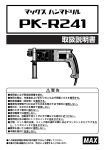
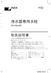
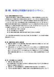
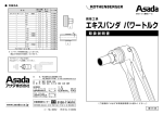
408-78056
25NOV2013 Rev A
0000
Instruction Sheet
取扱説明書
INDSUTRIAL MINI I/O PIERCING TYPE HAND TOOL
1. はじめに
この取扱説明書は、インダストリアルミニ I/O コネクタのピアッ
シング結線およびかしめを行う時の取扱方法を説明するもの
です。作業の前に必ずお読みください。
1. Introduction
This manual describes the piercing termination
and the crimping INDSUTRIAL MINI I/O procedure
with HAND TOOL. Read this manual thoroughly
before crimping work.
2. 適用製品
2. Applicable Products
Part No.(型番)
Descriptions (名称)
2229737-1
INDSUTRIAL MINI I/O PIERCING TYPE HAND TOOL
3. 適用コネクタ及びケーブル
3. Applicable Connector and Cable
取付適用規格を参照してください。
Refer Application Specification for details.
4. 関連規格
4. Related Documents
114-5506 : 取付適用規格
114-5506 : Application Specification
5. 工具仕様
工具重量 : 460 g
5. Tool Specification
Tool Weight
: 460 g
©2013 Tyco Electronics Japan G.K.,
a TE Connectivity Ltd. Company
All Rights Reserved
TE logo is a trademark.
* Trademark
タイコエレクトロニクス ジャパン合同会社、TE Connectivity Ltd. グループ
Other products, logos, and company names might be trademarks of their respective owners.
1 of 6
LOC B
Instruction Sheet
取扱説明書
408-78056
6. 各部の名称
6. Name of Parts
ダイス挿入部
Dies Insertion Area
ダイス
Dies
ダイス固定ノブ
Dies Locking Knob
ピアッシング部
Piercing Area
ハンドル
Handle
解除レバー
Release Lever
かしめ部
Crimping Area
Fig.1 各部の名称 Name of Parts
7. 工具概略
この手動工具はインダストリアルミニ I/O を組み立てる為
のツールです。ピアッシング結線部とかしめ部を持っていま
図3
す。また、コネクタの位置決めを行うホルダーを設けてありま
す。
この説明書により、工具の機能を正常に保ち、正しい加工
作業を行なって下さい。
7. Tool Outline
This Hand Tool is for assembling Industrial Mini
I/O Connector. And tool has piercing termination
and crimping. And also has holder due to be
easy to set the connector.
Refer this instruction sheet, Keep tool condition
and correct crimping work.
8. 取扱の注意点
8-1) 活線の加工は行わないでください。感電の恐れがあり
ます。
8-2) 指定のコネクタ以外は加工しないでください。不適合品
では加工不良により火災の原因になる恐れがありま
す。
8-3) 工具をハンマーやペンチの代わり等、加工作業以外に
は使用しないでください。また、工具を改造しないでくだ
さい。
8-4) ご使用前に各部の損傷がないことを確認し、損傷があ
る場合は使用しないでください。
圧着不良により火災の原因になる恐れがあります。
8-5) 高所作業の際は、工具の落下にご注意ください。事故
やけがの恐れがあります。
8-6) ハンドルを操作する時に、指を挟まないでください。
8. Attention for work
8-1) Do not assemble with wire that circuit is
running. Failure to do so may result in an
electric shock.
8-2) Do not crimp with NOT designated
Connector. Failure to do so may result in a
fire by assembly defect.
8-3) Do not use the tool besides assembly
work as hammer or pincer or etc. And do
not alter the tool.
8-4) Before use, check damage in the tool. If
there is damage, do not use the tool.
Failure to do so may result in a fire by
assembly defect.
8-5) Take care the drop of the tool when highplace work. Failure to do so may result in
a trouble or an injury.
8-6) When operating the handle. Please take a
care not to pinch the finger.
Rev A
2 of 6
Instruction Sheet
取扱説明書
408-78056
9. ピアッシング結線作業
9-1) 工具のハンドルをラチェットが解除されるまで握り、ハ
ンドルを開いた状態で、ハンドツールのロゴマーク面
を手前にして持ちます。
9-2) ケーブルハウジングの溝をピアッシング部凸に差し込
んでください。コネクタに上下方向はありません(Fig.2)
9-3) 次にハンドルを軽く握り、保持状態が問題ないことを
確認してください。
9-4) コネクタに挿入した電線が抜けない様に保持しながら
ハンドルを締め、ラチェットが開放されるまで握り締め
ます。
9-5) ハンドルを開き、結線されたコネクタを取出し、結線外
観の確認をして下さい。
3. Piercing termination method
9-1) Grip the handle to the ratchet will release. Set
the handle open with front of the surface that
Logo mark on the tool.
9-2) Insert the slot of “CABLE HSG” to the convex
of Piercing area of tool. There is not the top
and bottom in a connector(Fig.2)
9-3) Grip the handle a little to hold the connector
and confirm status of holding.
9-4) Grip the handle to the ratchet will release with
hold the connector to avoid wire position
move.
9-5) Open the handle. And take out the connector
and check the terminal Appearance.
ピアッシング部凸
Convex of Piercing area
ケーブルハウジングの溝
Slot of “CABLE HSG”
ツール
Tool
コネクタ
Connector
ツールのピアッシング部
Piercing area of the tool
コネクタセット後の状態
Status after setting
connector to the tool
Fig.2 コネクタの固定工程
Fig.2 The process of setting of connector
*プラグとリセは同様の工程となります。 Rec Connector is same as plug.
Rev A
3 of 6
Instruction Sheet
取扱説明書
408-78056
9. かしめ作業
9-1) 工具のハンドルをラチェットが解除されるまで握り、ハ
ンドルを開いた状態で、ハンドツールのロゴマーク面
を手前にして持ちます。
9-2) コネクタを Fig3 の方向でかしめ部ホルダーにセットし
てください。(Fig.3)
9-3) 次にハンドルを軽く握り、保持状態が問題ないことを
確認してください。
9-4) ハンドルを締め、ラチェットが開放されるまで握り締め
ます。
9-5) ハンドルを開き、コネクタを取出し、結線外観の確認を
して下さい。
3. Piercing termination method
9-1) Grip the handle to the ratchet will release. Set
the handle open with front of the surface that
Logo mark on the tool.
9-2) Set the connector to the holder of crimping
area in a direction of Fig.3.
9-3) Grip the handle a little to hold the connector
and confirm status of holding.
9-4) Grip the handle to the ratchet will release.
9-5) Open the handle. And take out the connector
and check the terminal Appearance.
ホルダー
Holder
コネクタ
Connector
ツールのかしめ部
Crimping area of the tool
コネクタの向き
Direction of the connector
コネクタセット後の状態
Status after setting connector
to the tool
Fig.3 コネクタの固定工程
Fig.3 The process of setting of connector
Rev A
4 of 6
Instruction Sheet
取扱説明書
408-78056
10. ダイスの取り外し方法
10-1) ハンドルを全開状態から4段階閉じます。(Fig.4)
10-2) ダイス固定ノブをハンドル側へ押し込んだまま、ダイ
スを引き抜きます。(Fig.5)
Fig.4
10. ダイスの取付方法
10-1) ハンドルを全開状態から4段階閉じます。(Fig.4)
10-2) ダイス固定ノブをハンドル側へ押し込んだまま、ダイ
スの溝とダイス挿入部の凸部を合わせ、差し込みま
す。(Fig.6)
10. Dies remove method
10-1) Close the handle to 4 steps from open
mode.(Fig.4)
10-2) During move Dies Locking Knob to the
handle side, withdraw Dies.(Fig.5)
Fig.4
10. Dies fixing method
10-1) Close the handle to 4 steps from open
mode.(Fig.4)
10-2) During move Dies Locking Knob to the
handle side, The slot of Dies and the convex
of Dies Insertion area are set and
inserted.(Fig.6)
Fig.6
Rev A
5 of 6
Instruction Sheet
取扱説明書
408-78056
10. 解除方法
異物の挟み込み等、組立作業を途中で解除する場合は
解除レバーを押し込みます。(Fig.7)
10. Care for Tool
Push Release lever when canceling on the way
of assembly.(Fig.7)
Fig.7
10. 工具の手入れ
10-1)刃型部はエアガン等を利用し、ゴミなどを取り除いて
下さい。
10-2) ハンドル開閉1000回毎に1回、指定箇所に機械油
を注油してください。(Fig.8)
10. Care for Tool
10-1) Remove the dust at anvil and crimper point
with Air-Gun.
10-2) Oil the designated point in machine oil every
1,000 times of steering wheel opening and
shutting once.(Fig.8)
注油箇所
Oil filling point
Fig.8
Rev A
6 of 6