1
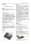
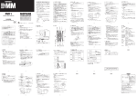
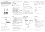
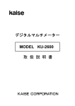
CD731
CD751
DIGITAL MULTIMETER
取扱説明書
INSTRUCTION MANUAL
目 次
【1】安全に関する項目∼ご使用の前に必ずお読みください。∼
1−1 警告マークなどの記号説明 ………………………………001
1−2 安全使用のための警告文 …………………………………001
1−3 最大過負荷保護入力値 ……………………………………002
【2】用途と特長
2−1 用 途 ………………………………………………………002
2−2 特 長 ………………………………………………………003
【3】各部の名称
3−1 本体・テストリード ………………………………………003
3−2 表示器 ………………………………………………………004
【4】機能説明 …………………………………………………………005
【5】測定方法
5−1 始業点検 ……………………………………………………007
5−2 電圧
(V)
測定 ………………………………………………008
5−2−1 直流電圧
(DCV ) …………………………………008
5−2−2 交流電圧
(ACV∼) …………………………………009
5−3 抵抗
(Ω)
測定 ………………………………………………011
5−4 導通
( )
チェック …………………………………………012
5−5 ダイオード
( )
テスト ……………………………………013
5−6 電流
(A)
測定 ………………………………………………014
5−6−1 直流・交流電流
(DC・ACμA、mA)………………014
5−6−2 直流・交流電流
(DC・AC20A)………………………016
5−7 別売付属品による測定 ……………………………………017
5−7−1 直流高電圧プローブ
(HVー60)
による測定 ………017
5−7−2 交流電流プローブ
(CLー20D)
による測定 ………018
5−7−3 直流・交流電流プローブ
(CLー22AD)
による測定 019
5−7−4 直流電流プローブ
(CL33DC)
による測定 …………020
【6】保守管理について
6−1 保守点検 ……………………………………………………021
6−2 校 正 ………………………………………………………021
6−3 内蔵電池の交換 ……………………………………………021
6−4 保管について ………………………………………………023
【7】アフターサービスについて
7−1 保証期間について …………………………………………023
7−2 修理について ………………………………………………023
7−3 お問い合わせ ………………………………………………024
【8】仕 様
8−1 一般仕様
( ……………………………………………………024
8−2 別売付属品 …………………………………………………026
8−3 測定範囲および許容差 ……………………………………026
保 証 書 ……………………………………最終ページにあります
CONTENTS
【1】SAFETY PRECAUTIONS : Before use, read the following safety precautions
1-1 Explanation of Warning Symbols …………………………029
1-2 Warning Instruction for safe use …………………………029
1-3 Maximum Overload Protection Input ……………………030
【2】APPLICATION AND FEATURES
2-1 Application……………………………………………………031
2-2 Features………………………………………………………031
【3】NAME OF COMPONENT UNITS
3-1 Multimeter, Test leads ……………………………………031
3-2 Display ………………………………………………………032
【4】DESCRIPTION OF FUNCTIONS ……………………………033
【5】MEASUREMENT PROCEDURE
5-1 Start-up Inspection …………………………………………035
5-2 Voltage measurement ………………………………………036
5-2-1 DCV Measurement ( ) ………………………………036
5-2-2 ACV Measurement (∼) ………………………………036
5-3 Resistance Measurement (Ω) ……………………………038
5-4 Checking Continuity( ) ……………………………………038
5-5 Testing Diode ( ) …………………………………………039
5-6 Current Measurement (A) …………………………………040
5-6-1 DC/AC μA・mA ………………………………………040
5-6-2 DC/AC 20A………………………………………………041
5-7 How to use optional products ……………………………042
5-7-1 HV Probe (HV-60) ………………………………………042
5-7-2 AC Clamp Probe (CL-20D) ……………………………042
5-7-3 DC・AC Clamp Probe (CL-22AD) ……………………043
5-7-4 DC Clamp Probe (CL33DC) ……………………………043
【6】MAINTENANCE
6-1 Maintenance and inspection ………………………………044
6-2 Calibration ……………………………………………………044
6-3 How to Replace Battery and Fuse ………………………044
6-4 Storage ………………………………………………………045
【7】AFTER-SALE SERVICE
7-1 Warranty and Provision ……………………………………046
7-2 Repair …………………………………………………………046
7-3 Sanwa web site ……………………………………………047
【8】SPECIFICATIONS
8-1 General Specifications………………………………………047
8-2 Optional Accessories ………………………………………049
8-3 Measurement Range and Accuracy ………………………049
【1】安全に関する項目∼ご使用の前に必ずお読みください。∼
このたびはディジタルマルチテスタCD731、751型をお買い上げ
いただき、誠にありがとうございます。
ご使用前にはこの取扱説明書をよくお読みいただき、正しく安全
にご使用ください。そして常にご覧いただけるように製品と一緒に
して大切に保管してください。
・・・ ・
本文中の“ 警告”および“ 注意”の記載事項は、やけどや感
・
電などの事故防止のため、必ずお守りください。
1-1 警告マークなどの記号説明
本器および『取扱説明書』に使用されている記号と意味について
:安全に使用するための特に重要な事項を示します。
・警告文はやけどや感電などの人身事故を防止するためのもの
です。
・注意文は本器を壊すおそれのあるお取り扱いについての注意
文です。
:直流
(DC)
:グランド
∼:交流
(AC)
+:プラス
Ω:抵抗
−:マイナス
:ブザー
:ヒューズ
:ダイオード
:二重絶縁または強化絶縁
1-2 安全使用のための警告文
警 告
以下の項目は、やけどや感電などの人身事故を防止するため
のものです。本器をご使用する際には必ずお守りください。
1. 6kVAを超える電力ラインでは使用しないこと。
2. AC30Vrms(42.4Vpeak)またはDC60V以上の電圧は人体に危険
なため注意すること。
3. 最大定格入力値を超える信号は入力しないこと。
4. 最大過負荷入力値を超えるおそれがあるため、誘起電圧、サー
ジ電圧の発生する
(モータ等)
ラインの測定はしないこと。
5. 本体またはテストリードが傷んでいたり、壊れている場合は
使用しないこと。
6. ケースまたは電池ぶたをはずした状態では使用しないこと。
− 1 −
17. ヒューズは必ず指定定格および仕様のものを使用すること。
ヒューズの代用品を用いたり短絡することは絶対にしない
こと。
18. 測定中はテストリードのつばよりテストピン側を持たないこと。
19. 測定中は他のファンクションまたは他のレンジに切り換え
たりしないこと。
10. 測定ごとのレンジ・ファンクション・測定端子の確認を確実に
行うこと。
11. 本器または手が水などでぬれた状態での使用はしないこと。
12. 内蔵電池および内蔵ヒューズ交換を除く修理・改造は行わ
ないこと。
13. 強力な電磁波を発生するもの、帯電しているものの近くで
は使用しないこと。
14. 年 1 回以上の点検は必ず行うこと。
15. 屋内使用
1-3 最大過負荷保護入力値
ファンクション
DCV
ACV
Ω・ ・ DC/AC
32μA
DC/AC
320μA、3200μA
DC/AC
32mA、320mA
DC/AC
20A
入力端子
V、
COM
Ω・ ・
、COM
μA・mA、
COM
μA・mA、
COM
μA・mA、
COM
20A、
COM
最大定格入力値
DC1000V
AC750V
電圧・電流
入力禁止
最大過負荷保護入力値
DC1000V, AC750V
または PEAK MAX 1000V
DC・AC500V
または PEAK MAX 700V
DC/AC 32μA
0.5A/250Vヒューズ保護
DC/AC 3200μA
0.5A/250Vヒューズ保護
DC/AC 320mA
0.5A/250Vヒューズ保護
DC/AC 20A
10秒以内
20A/250Vヒューズ保護
【2】用途と特長
2-1 用 途
本器は小容量電路の測定用に設計された、携帯用ディジタルマル
チメータです。小型通信機器や家電製品、電灯線電圧や各種電池の
測定などはもちろん、付加機能を使って回路分析などにも威力を発
揮します。
− 2 −
2-2 特 長
・IEC1010-1に準拠した安全設計
・3200カウント、円弧アナログバーグラフ付き
・スタンド機能付き
・データホールド、レンジホールド機能付き
(CD751)、オートパワーオフ
(CD731)
・約10分で作動するオートパワーセーブ
・電流測定もオート/マニュアル測定可能
(32μ、20Aは除く)
・20A測定端子には誤挿入防止のセーフティーカバー付き
・テストリード固定、壁掛け可能なホルスタ付き
・真の実効値測定
(CD751)
・本体ケースおよび回路基板には難燃材を使用
【3】各部の名称
3-1 本体・テストリード
ホルスタ(H-70)
液晶表示器
テストリード
固定部
壁掛け
データホールド
スイッチ
レンジ
ホールド
スイッチ
シフトスイッチ
電源スイッチ兼
ファンクションスイッチ
スタンド
セーフティ
カバー
COM端子
20A測定端子
V、Ω、●、●
μA、mA 測定端子
Fig 1
テストプローブ
(赤)
テストピン
(黒)
つば テストプローブ
プラグ
テストリード
(TL-21)
− 3 −
− 4 −
バーグラフの
マイナス極性表示
ダイオードテスト
動作表示
交流測定動作表示
データホールド動作表示
数値データの
マイナス極性表示
導通チェック動作表示
直流測定動作表示
Fig 2
小数点
数値表示
バーグラフスケール
高速バーグラフ
電池消耗警告
測定値単位表示
レンジホールド動作表示
3-2 表示器
【4】機能説明
○電源スイッチ兼ファンクションスイッチ
このスイッチを回して電源のON/OFFおよびV、Ω、●/●、
μA、mA、Aのファンクションを切り換えます。
○シフトスイッチ
(SHIFT)
直流/交流(電流ファンクション)の切り換えおよび●/●の切り
換えに使用します。このスイッチを押すと以下のように切り換わ
ります。
・電流ファンクションの場合
1 回押す毎に● → ∼ → ●となります。
・●/●の場合
1 回押す毎に● → ● → ●となります。
○レンジホールドスイッチ(RNG HOLD)
電圧、抵抗、電流(μA、mAのみ)
ファンクションの時特定のレン
ジにしたい場合使用します。このスイッチを押すとレンジが固定
され、マニュアルモードになります。このスイッチを押すたびに
レンジが移動しますので、表示器の単位と小数点の位置を確認し
ながら適正なレンジを選択してください。オートモードに復帰さ
せる場合は表示器の RH が消えるまでこのスイッチを押し続け
てください。
○データホールドスイッチ
(DATA HOLD)
表示器に表示されている測定データを固定させる時使用します。
このスイッチを押すと表示器に D.H が点灯し、その時点のデー
タ表示が固定され表示は変化しません。再びこのスイッチを押す
と表示器の D.H は消え、ホールド状態は解除され、測定状態に
戻ります。
○オートパワーオフ
(セーブ)
本器は約10分で自動的に表示が消え、電源の消費を抑えるオート
パワーオフ(セーブ)機能付きです。ただしオートパワーセーブは
表示が消えた状態でも多少電源は消費しますので長時間ご使用に
ならない場合はOFFレンジに合わせておいてください。また、オ
ートパワーオフ(セーブ)作動直前に本体より警告音が鳴りますの
でそのままご使用になりたい場合は、データホールドスイッチを
押してください。
− 5 −
警 告
入力信号を印加させたままファンクションスイッチをOFFに戻すこ
とは絶対にしないこと。必ず入力を切ってからOFFに戻すこと。
○スタンドの使用方法
本体を立ててご使用になりたい場合は、本体裏のスタンドを図の
ように立ててご使用ください。
Fig 3
○オーバー表示
(O.L)
本器に最大定格を超える入力が加わった場合には表示器に゛O.L゛
゛
表示が出ます。電圧、電流ファンクション等で、O.L 表示がされ
た場合はすみやかに入力を止めてください。
− 6 −
【5】測定方法
5-1 始業点検
警 告
1. 本体およびテストリードが傷んでいたり、壊れている場合は
使用しないこと。
2. テストリードが切れたりしていないことを確認すること。
▼
点検スタート
▼
はい
本体とテスト
リードの外観は破損して
いますか?
▼
はい
電池消耗表示
は点灯してい
ますか?□□
*
▼ いいえ
赤、黒のテスト
④ ピンをショート
します
▼いいえ
黒プラグをCOM
① 端子に差し込み
ます
▼
▼
赤プラグを●端子
に差し込みます
表示器の表示が10以下で
ブザーが鳴りますか?
▼
ファンクション
③ スイッチを●に
合わせます
電池を交換し、もう
一度点検をやり直し
てください
テストリードを交換
しても良くならない
場合は、修理が必要
です
▼
②
感電の恐れがありま
す。使用をやめ修理
してください
いいえ
▼
▼ はい
点検終了です
テストリードを交換
しもう一度やり直し
てください
*電池が消耗しすぎると表示
がまったく出なくなります。
④
③
②
①
Fig 4
− 7 −
5-2 電圧
(V)
測定
警 告
1. 最大定格入力電圧を超えた入力信号を加えないこと。
2. 測定中はファンクションスイッチを切り換えないこと。
3. 測定中はテストリードのつばよりテストピン側を持たないこと。
5-2-1 直流電圧
(DCV●) 最大測定電圧 DC1000V
1)測定対象
電池や直流回路の電圧を測ります。
2)測定レンジ
320mV∼1000Vまでの5レンジ
3)測定方法
①テストリードの赤プラグを+入力端子に、黒プラグを−入
力端子に差し込みます。
②ファンクションスイッチをDCVに合わせます。
③被測定回路のマイナス電位側に黒のテストピンを、プラス
電位側に赤のテストピンを接触させます。(逆に接続の場合
は゛
−゛
になります。
゛ 表示)
④表示器の表示を読み取ります。
⑤測定後は被測定回路から赤黒のテストピンをはずします。
●テストリード開放時に表示が変動しますが故障ではありま
せん。
⑤
④
③
③
⑤
電池
Battery
DCV
②
Fig 5
①
− 8 −
5-2-2 交流電圧
(ACV∼) 最大測定電圧 AC750V
1)測定対象
電灯線電圧などの正弦波交流電圧を測ります。
2)測定レンジ
3.2V∼750Vまでの4レンジ
3)測定方法
①テストリードの赤プラグを+入力端子に、黒プラグを−入
力端子に差し込みます。
②ファンクションスイッチをACVに合わせます。
③被測定回路に赤黒のテストピンを接触させます。
④表示器の表示を読み取ります。
⑤測定後は被測定回路から赤黒のテストピンをはずします。
⑤
⑤
④
③
コンセント
Outlet
ACV
②
①
Fig 6
〈交流
(AC)
測定についての注意〉
●CD731の場合
CD731の交流検波方式は平均値方式のため、正弦波以外の測定波
形では測定値に誤差が生じます。
(確度保証周波数範囲40∼400Hz)
− 9 −
●CD751の場合
1)真の実効値について
「平均値検波実効値」方式の測定の場合、入力信号が正弦波
で歪のない波形測定の時は誤差とはなりませんが、入力波形
が歪正弦波や非正弦波を測定した場合、実効値への換算が難
しくなりその分大きな誤差が生じてきます。
真の実効値では、入力信号の測定値は信号電力の尺度となり
ますので平均検波した値より、より有効な値として測定され
ます。本器ではこのTrueRMS(Root Meen Square)回路により
正弦波や方形波、三角波等非正弦波の実効値測定ができます。
2)クレストファクタ
(波高率)
CF(クレストファクタ)は信号のピーク値をその信号の実効値
で割った値で表されます。正弦波や三角波等最も一般的な波
形は相対的にクレスト係数が低くなっています。また、デュ
ーティサイクルの低いパルス列に類似した波形ではハイ・ク
レスト係数となります。代表的な各波形の電圧、クレストフ
ァクタは表を参考にしてください。
なお、クレストファクタ数は 3 以下で測定してください。
(確度保証周波数範囲:8-3参照)
入 力 波 形
正弦波
P
0
P・P
クレストファクタ 波形率
P/Vrms Vrms/Vavg
0 to PEAK
P
実効値
Vrms
平均値
Vavg
1.414
1.000
0.900
1.414
1.111
1.000
1.000
1.000
1
1.000
1.732
1.000
0.866
1.732
1.155
2・D
1
―
√
D
1
―
√
D
P
方形波
三角波
パルス
T2
D= ―
T1
0
P
0
T1
2.000
2 √D
T2
各波形の電圧一覧
●本器の交流測定は、AC+DCですので直流信号に重畳した
交流信号を測定しますと絶対値で測定されますのでご注意
ください。
●交流測定で入力信号の直流成分をカットしたい場合は入力
端子に直流防止用コンデンサ(0.2μ/1000V)を入れて測定
してください。
●インバータ電源回路の測定では誤動作することがあります。
− 10 −
5-3 抵抗
(Ω)
測定 最大測定抵抗 30MΩ
警 告
入力端子には外部よりの電圧を絶対に加えないこと。
1)測定対象
抵抗器や回路の抵抗を測ります。
2)測定レンジ
320Ω∼30Mまでの6レンジ
3)測定方法
①テストリードの赤プラグを+入力端子に、黒プラグを−入
力端子に差し込みます。
②ファンクションスイッチをΩに合わせます。
③被測定物に赤、黒のテストピンをあて測定します。
④表示器の表示値を読み取ります。
⑤測定後は被測定回路から赤黒のテストピンをはずします。
●入力端子間の開放電圧は約1.3Vです。
●測定に際しノイズの影響を受ける場合は、被測定物をCOM
の電位でシールドしてください。
●30MΩレンジでは測定物の誤差やノイズ、本器の誤差等に
より最大測定抵抗値まで測定できない場合もありますので
ご注意ください。
⑤
⑤
③
④
③
抵抗器
Resistor
Ω
②
Fig 7
①
− 11 −
5-4 導通
(●)
チェック
警 告
入力端子には電圧を絶対に加えないこと。
1)使用対象
配線の導通確認や選定に用います。
2)使用方法
①テストリードの赤プラグを+入力端子に、黒プラグを−入
力端子に差し込みます。
②ファンクションスイッチを●/● に合わせます。
③被測定回路または導線に赤黒のテストピンをそれぞれあて
チェックします。
④ブザーが鳴るか鳴らないかで導通を確認します。
※測定値が320Ω以下の場合は、その時の測定値が表示され
ます。
⑤測定後は被測定物から赤、黒のテストピンをはずします。
●入力端子間の開放電圧は約1.3Vです。
●被測定回路抵抗が約20Ω以下でブザーが発音します。
コンセント
Extension cord
⑤
③
③
⑤
④
●/●
②
ピー
①
Fig 8
− 12 −
5-5 ダイオード
(●)
テスト
警 告
入力端子には電圧を絶対に加えないこと。
1)使用対象
ダイオードの良否をテストします。
2)使用方法
①テストリードの赤プラグを+入力端子に、黒プラグを−入
力端子に差し込みます。
②ファンクションスイッチを●/● に合わせ、シフトスイッ
チで● にします。
③ダイオードのカソード側に黒のテストピンをアノード側に
赤のテストピンを接触させます。
④表示器にダイオードの順方向電圧降下が表示されているこ
とを確認します。
⑤ダイオードのカソード側に赤のテストピンを、アノード側
に黒のテストピンを接触させます。
⑥テストリード解放時の表示と同じ表示になっていることを
確認します。
⑦測定後は被測定物から赤黒のテストピンをはずします。
※④・⑥の確認ができれば、ダイオードは正常です。
●入力端子間の開放電圧は約3Vです。
アノード
Anode
カソード
Cathode
③③
④
⑥
ダイオード
Diode
/
⑦
②
⑤⑤
⑦
Fig 9
①
− 13 −
5-6 電流
(A)
測定
警 告
1. 入力端子には電圧を絶対に加えないこと。
2. 最大定格電流を超える入力は加えないこと。
3. 必ず負荷を通して本器が直列に接続されること。
電 源
電 源
(下図参照)
Power
Power
(×)
負 荷
Load
負 荷
Load
(○)
Fig 10
5-6-1 直流・交流電流(DC・ACμA、mA) 最大測定電流 DC/AC 320mA
1)測定対象
直流電流:電池や直流回路の電流を測ります。
交流電流:交流回路の電流を測ります。
2)測定レンジ
32μA∼320mAまでの5レンジ
(DC、AC)
3)測定方法
①テストリードの赤プラグをμA・mA入力端子に、黒プラグ
を−入力端子に差し込みます。
②ファンクションスイッチを測定したい電流ファンクション
に合わせ、シフトスイッチでDC●またはAC∼のいずれか
を選択します。
③被測定回路を切り離し負荷と直列になるように接続します。
④表示器の表示を読み取ります。
⑤測定終了後は被測定回路から赤黒のテストピンをはずします。
●電流測定では、電流レンジの内部抵抗が直列に入りこの分
だけ電流が減少しますので低抵抗回路では影響が大きくな
ります。
− 14 −
●入力信号を加えても表示が変化しない場合はヒューズが切
れている可能性がありますので、ヒューズが切れていない
か確認してください。
●本器の電流レンジは320μA∼3200μAと32mA∼320mAのレ
ンジ間はオートレンジです。レンジホールド・スイッチで
レンジを固定することも可能です。
●交流
(AC)
での確度保証周波数範囲は40Hz∼400Hz
(CD731)
、
40Hz∼1kHz(CD751)
です。
●本器の交流測定はAC+DCですので直流信号に重畳した交
流信号を測定しますと絶対値で測定されますのでご注意く
ださい。
注 意
電池レンジにおいて、表示器には単位信号表示はされません。
ファンクションスイッチにて測定レンジを確かめてから測定を
行って下さい。
④
電 池
Battery
⑤
抵抗器
Resistor
⑤
③
②
①
Fig 11
− 15 −
③
5-6-2 直流・交流電流(DC・AC20A) 最大測定電流 DC/AC 20A
警 告
1. 入力端子には電圧を絶対に加えないこと。
2. 発熱するため、測定は10秒以内にすること。
3. 発熱するため、測定間隔を5分以上とること。
4. リード線は過熱防止のため、伸ばした状態で測定すること。
1)測定対象
20A以下の回路電流を測定できます。
2)測定レンジ
20Aの1レンジ
(DC、AC)
3)測定方法
①セーフティーカバーを左側にスライドさせ、20A入力端子
を出します。
②テストリードの赤プラグを20A入力端子に、黒プラグを−
入力端子に差し込みます。
③ファンクションスイッチを20Aに合わせ、シフトスイッチで
DC●またはAC∼のいずれかを選択します。
④被測定回路を切り離し負荷と直列になるように接続します。
⑤表示器の表示を読み取ります。
⑥測定終了後は被測定回路から赤黒のテストピンをはずします。
●入力信号を加えても表示が変化しない場合はヒューズが切
れている可能性がありますので、ヒューズが切れていない
か確認してください。
●交流
(AC)
での確度保証周波数範囲は40Hz∼400Hz
(CD731)
、
40Hz∼1kHz
(CD751)
です。
注 意
電池レンジにおいて、表示器には単位信号表示はされません。
ファンクションスイッチにて測定レンジを確かめてから測定を
行って下さい。
⑤
⑥
④④
⑥
20A
③
②
①
Fig 12
− 16 −
・連続測定可能範囲:5A以下
・長時間の測定にはクランプ
プローブを御使用ください。
5-7 別売付属品による測定
警 告
1.使用する製品の最大定格入力値を超える入力信号は印加しな
いこと。
2.測定中は他のファンクションに切り換えないこと。
5-7-1 直流高電圧プローブ(HVー60)による測定 最大測定電圧 DC30kV
警 告
1.このプローブは微小電流回路測定用です。送電線などの強電
用には使用しないこと。
2.プローブの最大測定電圧
(DC30kV)
を超える電圧は印加しない
こと。
3.測定中は他のファンクションに切り換えないこと。
4.測定中はプローブのつばより測定ピン側を持たないこと。
1)測定対象:テレビのブラウン菅などのアノード電圧、フォー
カス用高電圧など高インピーダンス回路の電圧測定
2)測定レンジ:DC1000Vレンジを使用
3)測定方法
①高圧プローブの赤プラグをV入力端子に、黒プラグをCOM入
力端子に差し込みます。
②ファンクションスイッチをDCVに合わせ、レンジホールドス
イッチで1000Vレンジにします。
③被測定物のアースラインに黒のクリップを接続し、被測定箇
所にプローブ先端のピンをあてます。
④表示器の表示値を0.1倍してkV単位で読み取ります。
⑤測定後は被測定回路からピンを離してから、クリップをはず
します。
ブラウン管
CRT
アノード
Anode
⑤
④
③
DCV
③
②
①
Fig 13
− 17 −
5-7-2 交流電流プローブ(CLー20D)による測定 最大測定電流 AC200A
1)測定対象:家電機器の消費電流や電源設備など、50∼60Hzの
● 正弦波交流の測定に用います。
2)測定レンジ:20A,200Aの2レンジ
3)測定方法
①電流プローブの赤プラグをV入力端子に、黒プラグをCOM入
力端子に差し込みます。
②マルチメータのファンクションスイッチをACVに合わせ、
レンジホールドスイッチで3.2Vレンジにします。
③電流プローブのレンジ設定つまみを20Aまたは200Aレンジに
合わせます。
④電流プローブの鉄心を開き、被測定導体をクランプします。
⑤電流プローブのレンジが20Aの場合は表示値を10倍、200Aレ
ンジの場合は100倍して表示器の表示を読み取ります。
⑥測定後は電流プローブの鉄心を開き、被測定導体から電流プ
ローブをはずします。
⑤
②
ACV
④
⑥
③
①
Fig 14
− 18 −
5-7-3 直流・交流電流プローブ(CLー22AD)による測定 最大測定電流 DC/AC200A
1)測定対象
ACA:家電機器の消費電流や電源設備など、50∼60Hzの正弦
波交流の測定に用います。
DCA:自動車の電装回路の電流や直流機器の消費電流を測ります。
2)測定レンジ
AC20/200A,DC20A/200Aの各2レンジ
3)測定方法
①電流プローブの赤プラグをV入力端子に、黒プラグをCOM
入力端子に差し込みます。
②マルチメータのファンクションスイッチを直流電流(DCA)
ならDCVに合わせ、レンジホールドスイッチで320mVレン
ジにします。
交流電流(ACA)ならACVに合わせ、レンジホールドスイ
ッチで3.2Vレンジにします。
③電流プローブのレンジ設定つまみを20Aまたは200Aレンジ
に合わせます。
*直流測定の場合は電流プローブのゼロ調整つまみを回し0
(ゼロ)
調整します。
④電流プローブの鉄心を開き、被測定導体をクランプします。
⑤表示値を下記の倍率をかけて読み取ります。
DC20A→0.1倍 AC20A→100倍 DC200A→1倍 AC200A→1000倍 ⑥測定後は電流プローブの鉄心を開き、被測定導体から電流
プローブをはずします。
⑤
②
ACV
DCV
④
⑥
※
③
①
Fig 15
− 19 −
5-7-4 直流電流プローブ(CL33DC)による測定 最大測定電流 DC300A
1)測定対象:自動車の電装回路の電流や直流機器の消費電流を
測ります。
2)測定レンジ:30A,300Aの2レンジ
3)測定方法
①電流プローブの赤プラグをV入力端子に、黒プラグをCOM
入力端子に差し込みます。
②マルチメータのファンクションスイッチをDCVに合わせ、
レンジホールドスイッチで320mVレンジにします。
③電流プローブのレンジ設定つまみを30Aまたは300Aレンジ
に合わせます。
*電流プローブのゼロ調整つまみを回し0
(ゼロ)
調整します。
④電流プローブの鉄心を開き、被測定導体をクランプします。
⑤電流プローブのレンジが30Aの場合は表示値を0.1倍、300A
レンジの場合は1倍して表示器の表示を読み取ります。
⑥測定後は電流プローブの鉄心を開き、被測定導体から電流
プローブをはずします。
⑤
②
DCV
④
⑥
※
③
①
Fig 16
− 20 −
【6】保守管理について
警 告
1. この項目は安全上重要です。本説明書をよく理解して管理を
行ってください。
2. 安全と確度の維持のために1年に1回以上は校正、点検を実施
してください。
6-1 保守点検
1)外観
・落下などにより、外観が壊れていないか?
2)テストリードと内蔵ヒューズ
・入力端子にプラグを差し込んだときに緩みはないか?
・テストリードのコード部分が傷んでいないか?
・テストリードのどこかの箇所から芯線が露出していないか?
以上の項目に該当するものはそのまま使用せず、修理を依頼
してください。
●テストリードが切れたりしていないことを、P.7【5】5-1
を参照して確認してください。
6-2 校 正
校正、点検については三和電気計器
(株)
・羽村工場サービス課ま
でお問い合わせください。
(P.24[送り先]参照)
6-3
内蔵電池の交換
警 告
1. 入力端子に入力が加わった状態でリヤケースをはずすと感電
のおそれがあります。必ず入力が加わっていないことを確認
してから作業を行うこと。
2. 交換用ヒューズは同定格のものを使用すること。ヒューズの
代用品を用いたり、短絡することは絶対にしないこと。
3. リヤケースをはずしたとき、ヒューズおよび電池以外の内部
の部品や配線に手を振れないこと。
〈内蔵電池の交換方法〉
①ホルスタを本体より取りはずします。
②本体裏側のスタンドを開き、
プラスねじ回しで、
ねじをはずします。
③本体下側より開くようにリヤケースを取りはずし、消耗した電
池を取りだします。
④ 、 の極性を間違えぬよう注意し、新品の電池と交換します。
⑤リヤケースを取り付け、ねじ止めします。ホルスタ、スタンド
を元に戻します。
− 21 −
〈内蔵ヒューズの交換方法〉
使用ヒューズ定格
0.5A/250V(φ5.2×20mm 遮断容量300A)
20A/250V
(φ6.3×32mm 遮断容量1000A セラミック)
①ホルスタを本体より取りはずします。
②本体裏側のスタンドを開き、プラスねじ回しでねじをはずします。
③本体下側より開くようにリヤケースを取りはずし、溶断したヒ
ューズを取りだします。
④新品のヒューズと交換します。
⑤リヤケースを取り付けねじ止めします。ホルスタ、スタンドを
元に戻します。
単三乾電池
※リヤケース内側に
あります。
ねじ
−
+
20A/250V
ヒューズ
0.5A/250Vヒューズ
Fig 17
− 22 −
6-4 保管について
注 意
1. パネル、ケース等は揮発性溶剤に弱いため、シンナーやアル
コールなどでふいたりしないでください。お手入れをする場
合は、乾いた柔らかい布などで軽くふきとってください。
2. パネル、ケース等は熱に弱いため、高熱を発するもの
(はんだ
こて等)
の近くに置かないでください。
3. 振動の多い場所や落下のおそれがある場所には保管しないで
ください。
4. 直射日光下や高温または低温、多湿、結露のある場所での保
管は避けてください。
5. 長期間使用されない場合、内蔵電池を必ず抜いておいてくだ
さい。
以上の注意項目を守り、環境の良い場所
(P.24【8】参照)
に保管
してください。
【7】アフターサービスについて
7-1 保証期間について
本品の保証期間は、お買い上げ日より3年間です。
ただし、日本国内で購入し日本国内でご使用いただく場合に限り
ます。また、製品本体の確度は1年保証、製品付属の電池、ヒューズ、
テストリード等は保証対象外とさせていただきます。
7-2 修理について
1)修理依頼の前に次の項目をご確認ください。
・内蔵電池の容量はありますか?装着の極性は正しいですか?
・テストリードは断線していませんか?
・内蔵ヒューズは切れていませんか?
2)保証期間中の修理
・保証書の記載内容によって修理させていただきます。
3)保証期間経過後の修理
・修理によって本来の機能が維持できる場合、ご要望により
有料で修理させていただきます。
・修理費用や輸送費用が製品価格より高くなる場合もありま
すので、事前にお問い合わせください。
・本品の補修用性能部品の最低保有期間は、製造打切後 6 年
間です。この補修用性能部品保有期間を修理可能期間とさ
せていただきます。ただし購売部品の入手が製造会社の製
造中止等により不可能になった場合は、保有期間が短くな
る場合もありますのでお含みおきください。
− 23 −
4)修理品の送り先
・製品の安全輸送のため、製品の5倍以上の容積の箱に入れ、
十分なクッションを詰めてお送りください。
・箱の表面に「修理品在中」と明記してください。
・輸送にかかる往復の送料は、お客様のご負担とさせていた
だきます。
[送り先]三和電気計器株式会社・羽村工場サービス課
〒205-8604 東京都羽村市神明台4-7-15
TEL(042)
554-0113 FAX(042)
555-9046
5)補修用ヒューズについて
ヒューズは、上記サービス課あてに機種名とサイズ、定格を明
記し、ヒューズ代金と送料分の切手を同封してご注文ください。
〈形状〉
〈定格〉
〈価格〉
〈送料〉
φ5.2×20mm 0.5A/250V ¥42(単価¥40、消費税¥2) ¥120(10本まで)
部品番号 F0301ガラスヒューズ/遮断容量300A
φ6.3×32mm 20A/250V ¥457
(単価¥435、
消費税¥22)¥120
(10本まで)
部品番号 F0009セラミックヒューズ/遮断容量1000A
7-3
お問い合わせ
東京本社
:TEL(03)
3253-4871 FAX(03)
3251-7022
大阪営業所
:TEL(06)
6631-7361 FAX(06)
6644-3249
お客様計測相談室 0120-51-3930
受付時間 9:30∼12:00 13:00∼17:00(土日祭日を除く)
ホームページ :http://www.sanwa-meter.co.jp
【8】仕 様
8-1
一般仕様
(CD731、751)
動作方式
二重積分方式
AC検波方式
CD731(平均値方式)
AC検波方式
CD751(真の実効値方式)
表 示
数値部 最大 約3200カウント
表 示
バーグラフ部 最大 32セグメント
レンジ切り換え
オートおよびマニュアル
オーバー表示
表示器に“OL”と表示
極性切り換え
自動切り換え
(−のみ表示)
電池消耗表示
内部電池が消耗し、電池電圧が低下したとき表示器
サンプルレート
数値部 約2回/秒 バーグラフ部 約12回/秒
BT
に が点灯
− 24 −
確度保証温湿度範囲
23±5℃ 80%RH以下 結露のないこと
使用温湿度範囲
0∼40℃ 80%RH以下 結露のないこと
保存温湿度範囲
−10∼50℃ 70%RH以下 結露のないこと
(長時間使用しない場合は内蔵電池を外して保存すること)
使用環境条件
高度2000m以下 環境汚染度Ⅱ
電 源
単3電池(R6)2本
消費電力
約1.8mW TYP.(DCVにて、CD731)
消費電力
約8mW TYP.(DCVにて、CD751)
使用時間
約10分
(オートパーワーオフ、セーブ)
内蔵ヒューズ
φ5.2×20mm 0.5A/250V 遮断容量300A 、ガラス管
φ6.3×32mm 20A/250V 遮断容量1000A 、セラミック管
寸法・重量
165.5
(H)
×78(W)
×41.5(D)
mm
約310g
(CD731)
、約315g
(CD751)※ホルスタ装着時
付 属 品
取扱説明書 1、ホルスタ
(H-70)
テストリード
(TL-21)赤・黒 1 組
安全規格
IEC-1010
過電圧カテゴリⅢ保護クラスⅡに準拠
(EN61010-1)
(最高使用電圧DC1000V、AC750Vまで
においては過電圧カテゴリⅡに準拠)
EMC指令
EN50081-1(EN55022)、EN50082-1(EN61000-4-2)
EN50082-1(EN61000-4-3)、EN50082-1(ENV50204)
出荷時の電池について
工場出荷時にモニター用電池が組み込まれておりますので、記載
された電池寿命に満たないうちに切れることがあります。
※モニター用電池とは製品の機能や性能をチェックするための電池
のことです。
過電圧測定分類
過電圧測定分類(CATⅠ):コンセントから電源変圧器(トランス)
等を経由した機器内の二次側電路。
過電圧測定分類(CATⅡ):コンセントに接続する電源コード付き機
器の一次側電路。
過電圧測定分類(CATⅢ):直接分電盤から電気を取り込む機器の一次側
および分岐部からコンセントまでの電路。
− 25 −
8-2 別売付属品
・クリップアダプタ CL-11・高圧測定プローブ HV-60
・クランププローブ CL-20D、CL-22AD、CL33DC・携帯ケースC-SP
8-3 測定範囲および確度
許容差保証条件:23±5℃ 80%RH 結露のないこと
●CD731
ファンクション
直流電圧
(DCV )
交流電圧
(ACV∼)
抵 抗
(Ω)
直流電流
(DCA )
交流電流
(ACA∼)
レンジ
確 度
入力抵抗
備 考
±
(0.5%rdg+2dgt) 約100MΩ以上
320.0mV
約11MΩ
3.200V
32.00V
±
(0.9%rdg+2dgt)
約10MΩ
320.0V
1000V
約11MΩ
3.200V
確度保証周波
*
32.00V
数範囲
±
(1.2%rdg+5dgt)
約10MΩ
320.0V
:40∼400Hz
750V
320.0Ω
3.200kΩ
±
(1.2%rdg+2dgt) ・開放電圧は約1.3V
32.00kΩ
・測定電流は被測定抵抗の抵抗
320.0kΩ
値によって変化します。
3.200MΩ
±
(2.0%rdg+2dgt)
30.00MΩ
±
(5.0%rdg+2dgt)
約5kΩ
32.00μA
320.0μA
約500Ω
3200μA
±
(1.4%rdg+2dgt)
32.00mA
約5Ω
320.0mA
20.00A
±
(2.0%rdg+2dgt)
約0.005Ω
32.00μA
約5kΩ
320.0μA *
確度保証周波
約500Ω
3200μA
±
(1.8%rdg+5dgt)
数範囲
32.00mA
:40∼400Hz
約5Ω
320.0mA
20.00A
約0.005Ω
*±(2.5%rdg+5dgt)
・約20Ω以下でブザーが発音します。
・開放電圧は約1.3V
導通チェック
( )
ダイオードテスト
・開放電圧は約3V
( )
− 26 −
●CD751
ACVの確度は、レンジの5%∼100%で規定。
クレストファクタ:<3:1
ファンクション
直流電圧
(DCV )
交流電圧
(ACV∼)
抵 抗
(Ω)
直流電流
(DCA )
交流電流
(ACA∼)
レンジ
確 度
入力抵抗
備 考
320.0mV
±
(0.5%rdg+2dgt) 約100MΩ以上
3.200V
約11MΩ
32.00V
±
(0.9%rdg+2dgt)
320.0V
約10MΩ
1000V
3.200V
約11MΩ
確度保証周波数範囲
32.00V
±
(1.2%rdg+8dgt)
3.2Vレンジ:40∼500Hz
320.0V
約10MΩ
32Vレンジ以上:40∼1kHz
750V
320.0Ω
3.200kΩ
±
(1.2%rdg+2dgt) ・開放電圧は約1.3V
32.00kΩ
・測定電流は被測定抵抗の抵抗
320.0kΩ
値によって変化します。
3.200MΩ
±
(2.0%rdg+2dgt)
30.00MΩ
±
(5.0%rdg+2dgt)
32.00μA
約5kΩ
320.0μA
約500Ω
±
(1.4%rdg+2dgt)
3200μA
32.00mA
約5Ω
320.0mA
20.00A
±
(2.0%rdg+2dgt)
約0.005Ω
32.00μA
約5kΩ
320.0μA
約500Ω
確度保証周波
±
(1.8%rdg+10dgt)
3200μA
数範囲
32.00mA
約5Ω
:40∼1kHz
320.0mA
20.00A
約0.005Ω
±(2.5%rdg+10dgt)
・約20Ω以下でブザーが発音します。
・開放電圧は約1.3V
導通チェック
( )
ダイオードテスト
・開放電圧は約3V
( )
rdg:reading(読みとり値)
dgt:digits(最下位けた)
− 27 −
*:トランスや大電流路など強磁界の発生している近く、また無線
機など強電界の発生している近くでは正常な測定ができない場
合があります。
◎確度計算方法
例)直流電圧測定(DCmV)
表 示 値:100.0mV
レンジ確度:320mVレンジ・・・・±(0.5%rdg+2dgt)
)
=±0.7
[mV]
誤 差:±
(100.0
[mV]
×0.5%+2※[dgt]
(99.3∼100.7mVの範囲内)
真 値:100.0[mV]±0.7[mV]
※この場の2dgtは0.2mVに相当します。
ここに掲載した製品の仕様や外観は改良等の理由により、予告
なしに変更することがありますのでご了承ください。
− 28 −
【1】 SAFETY PRECAUTIONS : Before use, read the following safety precautions
This instruction manual explains how to use your multimeter
CD731, 751 safely. Before use, please read this manual thoroughly.
After reading it, keep it together with the product for reference to it
when necessary.
The instruction given under the heading "●WARNING" "●CAUTION"
must be followed to prevent accidental burn or electrical shock.
1-1 Explanation of Warning Symbols
The meaning of the symbols used in this manual and attached to
the product is as follows.
:Very important instruction for safe use.
・The warning messages are intended to prevent accidents to
operating personnel such as burn and electrical shock.
・The caution messages are intended to prevent damage to
the instrument.
:DC
:Glaund
∼:AC
+:Plus
Ω:Resistance
−:Minus
:Continuity
:Fuse
:Diode
:Double insulation
1-2 Warning Instruction for safe use
WARNING
To ensure that the meter is used safely, Be sure to observe
the instruction when using the instrument.
1. Never use meter on the electric circuit that exceed 6kVA.
2. Pay special attention when measuring the voltage of AC
30Vrms (42.4 Vpeak) or DC 60V or more to avoid injury.
3. Never apply an input signals exceeding the maximum rating
input value.
4. Never use meter for measuring the line connected with
equipment (i.e.motors) that generates induced or surge
voltage since it may exceed the maximum allowable voltage.
− 29 −
5. Never use meter if the meter or test leads are damaged or
broken.
6. Never use uncased meter.
7. Be sure to use a fuse of the spesified rating or type. Never
use a substitute of the fuse or never make a short circuit of
the fuse.
8. Always keep your fingers behind the finger guards on the
probe when making measurements.
9. Be sure to disconnect the test pins from the circuit when
changing the function or range.
10. Be sure to disconnect the test pins from the circuit when
changing the function or range.
11. Never use meter with wet hands or in a damp environment.
12. Never open tester case except when replacing batteries or
fuse. Do not attempt any alteration of original specifications.
13. Do not use the device near an item of strong electromagnetic
generation or a charged item.
14. To ensure safety and maintain accuracy, calibrate and check
the tester at least once a year.
15. Indoor use
1-3 Maximum Overload Protection Input
Function
DCV
ACV
Ω・ ・
DC/AC
32μA
DC/AC
320μA、3200μA
DC/AC
32mA、320mA
DC/AC
20A
Input
V、
COM
Ω・ ・
、COM
μA・mA、
COM
μA・mA、
COM
μA・mA、
COM
20A、
COM
Maximum rating Maximum overload
input value
protection input
DC1000V
AC750V
Voltage and current
input prohibited
DC/AC 32μA
DC/AC 3200μA
DC/AC 320mA
DC/AC 20A
10sec.
− 30 −
DC1000V,AC750V
or PEAK MAX 1000V
DC・AC500V
or PEAK MAX 700V
0.5A/250V
Fuse protected
0.5A/250V
Fuse protected
0.5A/250V
Fuse protected
20A/250V
Fuse protected
【2】APPLICATION AND FEATURES
2-1 Application
This instrument is portable multimeter designated for
measuremaent of weak current circuit.
2-2 Features
・The instrument has been designed in accordance with the safety
standard IEC 1010-1.
・3200 counts and circular bar graph available.
・A stand has adhered.
・Data hold and range hold.
・Auto power off(CD731)、Auto power save (CD751)(10min.)
・The current function is the auto range. (except 32μA、20A)
・The testlead fixing feature and holster has adhered.
・AC Measurement is the True RMS (CD751) .
・Main unit case and the circuit board is made of fire retarding
materials.
【3】NAME OF COMPONENT UNITS
3-1 Multimeter, Test leads
Holster(H-70)
Display
Test lead fix
Data hold
switch
Range hold
switch
Shift switch
Power switch and
function switch
Stand
Safety cover
COM input
terminal
20A input
terminal
V、Ω、●、●、μA
mA input terminal
Test probe (red)
Test pin
Finger guards
Test probe (black)
Plug
Test lead (TL-21)
− 31 −
Fig 1
− 32 −
Minus polarity display
for bar graph data
Testing diode display
AC measurement display
Data hold display
Minus polarity display
for numeral data
Checking countinoity display
DC mearsurement display
Fig 2
Decimal point
Numeral data display
Bar graph scale
Hight speed bar
graph
Battery dischage
warning
Measurement
unit display
Range hold display
3-2 Display
【4】DESCRIPTION OF FUNCTIONS
○Power switch and function switch
Turn this switch to turn on and off the power and select the functions
of V,Ω,● /● ,μA,mA,A.
○Shift switch
When this switch is pressed (→), the modes change as follows.
・In the case of current function the mode change as ● → ∼ →
● .
・In the case of ●/● the mode change as ● →● →● .
○Range hold switch (R.H)
Pressing this switch once sets the manual mode and the range is
fixed. Once the manual mode is set, the range moves each time
this switch is pressed. (only V,Ω,μA, mA) Checking the unit on
the display and the place of the decimal point, select a desired
range. To return to the auto mode, keep pressing this switch until
RH on the display disappears.
○Data hold switch (D.H)
When this switch is pressed, the data display at that time continues
(DH lights on the display). When the measuring input changes,
the display will not change.
When this switch is pressed again, the hold status is canceled you
can return to the measuring status. (DH on the display disppears.)
○Auto power off, Auto power save
This equipment incorporates an auto power off and save which
turns off the display in about 10 minutes to save power. Just
before the auto power save is activated, a warning sound is
issued.
If you want to continue to use the equipment, press the data hold
switch. If you will not use the equipment for long hours, keep the
functions switch at OFF.
− 33 −
○How to Use the Stand
Please use the stand that there is on the side of rear case like a
figure.
Fig 3
− 34 −
【5】MEASUREMENT PROCEDURE
5-1 Start-up Inspection
WARNING
1. Never use meter if the meter or test leads are damaged or
broken.
2. Make sure that the test leads are not cut or otherwise damaged.
START
▼
No damage
▼
Stop using it and
have it repaired.
▼
▼
▼
②Connect the test
lead of red plug to
the ● terminal.
▼
Check continuity of
test leads.
① Connect the test
lead of black plug to
the COM terminal.
▼
Damaged
▼
Main unit and
test leads
damaged?
④Short the red and
black test pins.
▼
Display shows
00.0∼01.0?
No
Yes ▼
▼
③Set the function
switch at ●.
No problem.
Start measurement.
④
③
①
②
Fig 4
− 35 −
5-2 Voltage measurement
WARNING
1.Never apply an input signals exceeding the maximum rating
input value.
2.Be sure to disconnect the test pins from the circuit when
changing the function.
3.Always keep your fingers behind the finger guards on the
probe when making measurements.
5-2-1 DCV Measurement (●) Maximum rating input value 1000VDC
1) Applications
Measures batteries and d.c. circuits.
2) Measuring ranges
320mV∼1000V (5 ranges)
3) Measurement procedure (See fig5, page8)
①Connect the test lead of the black plug to the COM input
terminal and the red plug to the "V" input terminal.
②Set the function switch at "DCV" function.
③Apply the black test pin to the negative potential side of the circuit
to measure and the red test pin to the positive potential side.
④Read the value on the display.
⑤After measurement, remove the red and black test pins from
the circuit measured.
5-2-2 ACV Measurement (∼) Maximum rating input value 750VAC.
1) Applications
Measures sine-wave AC voltages such as lighting voltages.
2) Measuring ranges
3.2V∼750V (4 ranges)
3) Measurement procedure (See fig6, page9)
①Connect the test lead of the black plug to the COM input
terminal and the red plug to the "V" input terminal.
②Set the function switch at "ACV" function.
③Apply the black and red test pin to measured circuit.
④Read the value on the display.
⑤After measurement, remove the red and black test pins from
the circuit measured.
− 36 −
[Caution for ACV measurement of CD731]
●Since this instrument employs the means value system for its AC
voltage measurement circuit, AC waveform other than sine wave
may cause error.
●There occurs error under such frequencies other than specified
specification.
[Caution for ACV measurement of CD751]
●True Root Mean Square Value
When measurement is taken by "average value detection r.m.s.",
no error is caused as the input signal is sine wave with no distortion.
However, if the input waveform is distorted sine wave or nonsinusoidal wave, conversion to root mean square values is very
difficult, resulting in a large error.
When measurement is taken by true r.m.s., the measurement value
of input signal becomes the scale of the signal power and therefore
provide more effective values than those obtained by average value
detection. This multimeter imploys this true RMS (Root Mean
Square) circuit, which enables measurement of sine wave and nonsinusoidal waves like square wave and triangular wave in r.m.s.
●Crest Factor
The crest factor (CF) is expressed by a value obtained by dividing
the peak value of the signal by its RMS value. Most common
waveforms such as sine wave and triangular wave have a relatively
low crest factor. Waveforms similar to a pulse train of low duty
cycle have a high crest factor. The voltages and crest factors of
typical waveforms are shown in the table.
Note that measurement should be taken with the crest factor
below 3.
Crest factor Form factor
P/Vrms P/Vrms / Vavg
0 to Peak
P
RMS value
Vrms
Average
value Vavg
Sine
wave
1.414
1.000
0.900
1.414
1.111
Square
wave
1.000
1.000
1.000
1
1.000
Triangular
wave
Pulse
T2
D= ―
T1
1.732
1.000
0.866
1.732
1.155
2・D
1
―
√
D
1
―
√
D
Input Waveform
2.000
2 √D
Voltages and Crest Factors of Various Waveforms
●It may malfunction when measuring voltage/current in the
inverter circuit.
− 37 −
5-3 Resistance Measurement (Ω)
WARNING
Never apply voltage to the input terminals.
1) Application
Resistance of resistors and circuits are measured.
2) Measuring ranges
320Ω∼30MΩ (6 range)
3) Measurement procedure (See fig7, page11)
①Connect the black plug of the test lead to the COM input
terminal and the red plug to the "Ω" input terminal.
②Set the function switch at "Ω" function.
③Apply the black and red test pin to measured circuit.
④Read the value on the display.
⑤After measurement, remove the red and black test pins from
the circuit measured.
●If measurement is likely to be influenced by noise, shield the
object to measure with negative potential (test lead black) .
●If a test pin is touched by a finger during measurement,
measurement will be influenced by the resistance in the human
body to result in measurement error.
●The input terminals release voltage is about 1.3V.
5-4
Checking Continuity (●)
WARNING
Never apply voltage to the input terminals.
1) Application
Checking the continuity of wiring and selecting wires.
2) How to use (See fig8, page12)
①Connect the test lead of the black plug to the COM input
terminal and the red plug to the "● " input terminal.
②Set the function switch at "● /● " function.
③Apply the red and black test pins to a circuit or conductor to
measure.
④The continuity can be judged by whether the buzzer sounds
or not.
⑤After measurement, release the red and black test pinsfrom
the object measured.
− 38 −
●The buzzer sounds when the resistance in a circuit to measure
is less than about 20Ω.
●The input terminals release voltage is about 1.3V.
5-5
Testing Diode (● )
WARNING
Never apply voltage to the input terminals.
1) Application
The quality of diodes is tested.
2) How to use (See fig9, page13)
①Connect the test lead of the black plug to the COM input
terminal and the red plug to the "● " input terminal.
②Set the function switch at "● /● " function and push the
shift switch.
③Apply the black test pin to the cathode of the diode and the
red test pin to the anode.
④Make sure that the display shows a diode forward voltage drop.
⑤Apply the red test pin to the cathode of the diode and the black
test pin to the anode.
⑥Make sure that the display is the same as that when the test
leads are released.
⑦After measurement, release the red and black test pins from
the object measured.
Judgement:When the items ④ and ⑥ are normal, the diode is good.
●The input terminals release voltage is about 3V.
− 39 −
5-6 Current Measurement (A)
WARNING
1. Never apply voltage to the input terminals.
2. Be sure to make a series connection via load.
(See fig10, page14)
3. Do not apply an input exceeding the maximam rated current
to the input terminals.
5-6-1 DC/AC μA・mA Measurement Maximum rating input value DC/AC 320mA
1) Applications
Current in DC and AC circuit is measured.
2) Measuring ranges
32μA∼320mA (5 range)
3) Measurement procedure (See fig11, page15)
①Connect the black plug of the current probe to the COM
input terminal and the red plug to the "μA ・mA" input
terminal.
②Select either current function, and select either DC● or AC
∼ with the shift switch.
③Apply the black test pin to the negative potential side of the
circuit to measure and the red test pin to the positive potential
side.
④Read the value on the display.
⑤After measurement, remove the red and black test pins from
the circuit measured.
●If the display will not change when an input signal is applied
(measurement is not possible), a probable cause is a blown fuse.
●The current ranges of 320μA to 3200μA and 32mA to 320mA
of this equipment are the auto ranges. The ranges can also be
fixed using the range hold switch.
●The accuracy guaranteed frequency range 40Hz to 400Hz
(CD731), 40Hz∼1kHz (CD751) .
●For the μA・mA range, no unit symbol will be indicated.
− 40 −
5-6-2 Current Measurement Maximum rating input value DC/AC 20A
WARNING
1. Never apply voltage to the input terminals.
2. Finish measurement within 10seconds to prevent heat
generation.
3. Provide intervals of 5 minutes or longer between measurements
to prevent heat generation.
4. Perform measurement with the leads kept straight to prevent
overheat.
1) Applications
Current in DC and AC circuit is measured.
2) Measuring ranges
20A
3) Measurement procedure (See fig12, page16)
①Connect the test lead of the black plug to the COM input
terminal and the red plug to the "20A" input terminal.
②Set the function switch at "20A" function, and select either
DC● or AC∼ with the shift switch.
③Apply the black test pin to the negative potential side of the
circuit to measure and the red test pin to the positive
potential side.
④Read the value on the display.
⑤After measurement, remove the red and black test pins from
the circuit measured.
●If the display will not change when an input signal is applied
(measurement is not possible), a probable cause is a blown fuse.
●The accuracy guaranteed frequercy range is 40Hz to 400Hz
(CD731), 40Hz∼1kHz (CD751)
●For the 20A range, no unit symbol will be indicated.
●5A Continuous : 20A for 10 secound max. with 5 minutes cool
down interval.
− 41 −
5-7 How to use optional products
WARNING
1.Never apply input signals exceeding the maximum rating input
value of optional products.
2.Be sure to disconnect the test pins from the circuit when
changing the function.
5-7-1 HV Probe (HV-60)Maximum measurement value DC30kV
WARNING
1.The probe is designed for the measurement of very small DC
circuit. Never use the probe to measure high voltage in power
Iines, Such as transmission and distribution lines; it is very
dangerous.
2.Never apply an input signals exceeding the maximum
rating(30kV)of HV prove.
3.Be sure to disconnect the test pins from the circuit when
changing the function.
4.Alwaya keep your fingers behind the finger guards on the
probe when making measurement.
〈Measurement procedure〉(See fig 13, page 17)
①Connect the black plug of the HV Probe to the COM terminal
and the red plug to the V terminal.
②Set the function at DCV and set the 1000V range with the
range hold switch.
③First, connect the black clip of the probe to the earth
line(−)in the circuit to be measured, and then apply the
measuring pin on the probe to measuring point.
④Read the value on the display in kV unit after multiplying
indicated value by 0.1.
5-7-2 AC Clamp Probe (CL-20D)Maximum measurement value AC200A
〈Measurement procedure〉(See fig 14, page 18)
①Connect the current probe of the black plug to the COM
terminal and the red plug to the V terminal.
②Set the function at ACV and set the 3.2V range with the
range hold switch.
− 42 −
③Select either 20A or 200A with selector knob of clamp probe.
④Open the clamp part, have electric line(one line) clamped.
⑤Read the value on the display in A unit and when current
probe of the 20A range after multiplying indicated value by
10, and the 200A range after multiplying indicated value by 100.
⑥After measurement, open the clamp part and release clamp
probe from the electric wire.
5-7-3 DC・AC Clamp Probe(CL-22AD) Maximum measurement value DC/AC200A
〈Measurement procedure〉(See fig 15, page 19)
①Connect the current probe of the black plug to the COM
terminal and the red plug to the V terminal.
②Set the function at DCV or ACV. Set the range is 320mV
with range hold switch at DC measurement. Set the range
is 3.2V with range hold switch at AC measurement.
③Select either 20A or 200A with selector knob of clamp probe.
※The zero point varies when the DCA is mesured, so be sure
to check that the moltimeter indicates zero. If not zero,
adjust the indication to the zero point by torning the zero
adjusting knob(OADJ).
④Open the clamp part, have electric wire(one line) clamped.
⑤Read the value on the display as follows.
DC20A→multiplying by 0.1 AC20A→multiplying by 100
DC200A→multiplying by 1 AC200A→multiplying by 1000
⑥After measurement, open the clamp part and release clamp
probe from the electric wire.
5-7-4 DC Clamp Probe(CL33DC) Maximum measurement value DC300A
〈Measurement procedure〉(See fig 16, page 20)
①Connect the current probe of the black plug to the COM
terminal and the red plug to the V terminal.
②Set the function at DCV and set the 320mV range with the
range hold switch.
③Select either 30A or 300A with selector knob of clamp probe.
※The zero point varies when the DCA is mesured, so be sure
to check that the moltimeter indicates zero. If not zero,
adjust the indication to the zero point by torning the zero
adjusting knob(OADJ).
④Open the clamp part, have electric line(one line)clamped.
⑤Read the value on the display in A unit and when current
probe of the 30A range after multiplying indicated value by
0.1, and the 300A range after multiplying indicated value by 1.
⑥After measurement, open the clamp part and release clamp
probe from the electric wire.
− 43 −
【6】MAINTENANCE
WARNING
1. This section is very important for safety. Read and understand
the following instruction fully and maintain your instrument
properly.
2. The instrument must be calibrated and inspected at least
once a year to maintain the safety and accuracy.
6-1 Maintenance and inspection
1. Appearance
・Is the appearance not damaged by falling?
2. Test leads and fuse
・Is the cord of the test leads not damaged?
・Is the core wire not exposed at any place of the test leads?
If your instrument falls in any of the above items, do not use it
and have it repaired or replace it with a new one.
●Make sure that the test leads are not cut, referring to the section.
6-2 Calibration
The calibration and inspection may be conducted by the dealer.
For more information, please contact the dealer.
6-3
How to Replace Battery and Fuse
WARNING
1. If the rear case is removed with input applied to the input
terminals, you may get electrical shock.
Before starting the work, always make ure that no inputs is
applied.
2. Be sure to use the fuse is same rating so as to ensure safety
and performance of tester.
3. When operator remove the rear case, do not touch the
internal parts or wire with hand.
〈How to replace the battery〉
①Remove the holster from the meter.
②Opening the stand of the meter reverse side, and remove the
screw with a screwdriver.
③Take out the battery and replace it with a new one.
④Attach the rear case and fix it with the screw.
⑤The stand and holster are returned.
− 44 −
〈How to replace the fuse〉
Fuse of the Specified Rating and Type
0.5A/250V φ5.2×20mm Blowout capacity:300A
20A/250V φ6.3×32mm Blowout capacity:1000A Ceramic
①Remove the holster from the meter.
②Opening the stand of the meter reverse side and remove the
screw with a screwdriver.
③Pull out the fuse out of holder on the circuit board and replace it.
④Put back the rearcase where it was and tighten the screw.
⑤Check and see whether or not indications of respective ranges
are normal.
Battery(R6,1.5V×2)
※There is a inside
of rear case.
Screw
−
+
20A/250V
Fuse
0.5A/250V Fuse
Fig 17
6-4 Storage
CAUTION
1. The panel and the case are not resistant to volatile solvent and
must not be cleaned with thinner or alcohol.
For cleaning, use dry, soft cloth and wipe it lightly.
2. The panel and the case are not resistant to heat. Do not place the
instrument near heat-generating devices (such as a soldering iron) .
3. Do not store the instrument in a place where it may be subjected
to vibration or from where it may fall.
4. For storing the instrument, avoid hot, cold or humid places or
places under direct sunlight or where condensation is anticipated.
Following the above instructions, store the instrument in good
environment.
− 45 −
【7】AFTER-SALES SERVICE
7-1 Warranty and Provision
Sanwa offers comprehensive warranty services to its end-users and
to its product resellers. Under Sanwa's general warranty policy, each
instrument is warranted to be free from defects in workmanship or
material under normal use for the period of one (1) year from the date
of purchase.
This warranty policy is valid within the country of purchase only, and
applied only to the product purchased from Sanwa authorized agent or
distributor.
Sanwa reserves the right to inspect all warranty claims to determine
the extent to which the warranty policy shall apply. This warranty shall
not apply to fuses, disposables batteries, or any product or parts,
which have been subject to one of the following causes:
1.A failure due to improper handling or use that deviates from the
instruction manual.
2.A failure due to inadequate repair or modification by people other
than Sanwa service personnel.
3.A failure due to causes not attributable to this product such as fire,
flood and other natural disaster.
4.Non-operation due to a discharged battery.
5.A failure or damage due to transportation, relocation or dropping
after the purchase.
7-2 Repair
Customers are asked to provide the following information when
requesting services:
1.Customer name, address, and contact information
2.Description of problem
3.Description of product configuration
4.Model Number
5.Product Serial Number
6.Proof of Date-of-Purchase
7.Where you purchased the product
Please contact Sanwa authorized agent / distributor / service provider,
listed in our website, in your country with above information. An
instrument sent to Sanwa / agent / distributor without those
information will be returned to the customer.
− 46 −
Note:
1)Prior to requesting repair, please check the following:
Capacity of the built-in battery, polarity of installation and
discontinuity of the test leads.
2)Repair during the warranty period:
The failed meter will be repaired in accordance with the conditions
stipulated in 7-1 Warranty and Provision.
3)Repair after the warranty period has expired:
In some cases, repair and transportation cost may become higher
than the price of the product. Please contact Sanwa authorized
agent / service provider in advance.
The minimum retention period of service functional parts is 6 years
after the discontinuation of manufacture. This retention period is the
repair warranty period. Please note, however, if such functional parts
become unavailable for reasons of discontinuation of manufacture,
etc., the retention period may become shorter accordingly.
4)Precautions when sending the product to be repaired:
To ensure the safety of the product during transportation, place the
product in a box that is larger than the product 5 times or more in
volume and fill cushion materials fully and then clearly mark “Repair
Product Enclosed” on the box surface. The cost of sending and
returning the product shall be borne by the customer.
7-3 SANWA web site
http://www.sanwa-meter.co.jp
E-mail: [email protected]
【8】SPECIFICATIONS
8-1 General Specifications
Measuring Method
Display
Range Selection
Over Display
Polarity
Battery Discharge
Dual integration
Counter:approx.3200counts
Bar graph:32 segments max.
Auto and Manual ranges
"O.L" mark indication
Automatic selection (only "−" is displayed)
If the internal battery has been consumed
and the voltage drops, the display shows
− 47 −
Sampling Rate
Accuracy Assurance
Temperature/Humidity Range
Operating
Temperature/Humidity Range
Storage
Temperature/Humidity Range
Approx.2times/sec (numeral display)
Approx.12times/sec (bar graph)
23±5℃ 80%RH max. No condensation.
0∼40℃ 80%RH max. No condensation.
−10∼50℃ 70%RH max. No condensation.
Operating altitude〈2000m Pollution degree Ⅱ
R06 (IEC) dry battery, 2 pieces
Approx. 1.8mW TPY (at DCV, CD731)
Approx. 8mW TPY (at DCV, CD751)
Battery Life
10 min. (auto power save)
0.5A/250V φ5.2×20mm Blowout capacity 300A
Fuse protection
20A/250V φ6.3×32mm Blowout capacity 1000A
Dimension and Weight 165.5 (H) ×78 (W) ×41.5 (D) mm approx.310g(CD731)
165.5 (H) ×78 (W) ×41.5 (D) mm approx.315g(CD751)
Accessories
Instruction manual 1, Holster (H-70)
Test lead (TL-21) 1
Safety
Designed to protection Class requirement
of IEC 1010-1 overvoltage category Ⅲ
(Max.DC・AC600V) (EN61010-1)
(Max.DC1000V, AC750V overvoltage category Ⅱ)
EMC
EN50081-1 (EN55022), EN50082-1 (EN61000-4-2)
EN50082-1 (EN61000-4-3), EN50082-1 (ENV50204)
Environmental Condition
Power Supply
Power Consumption
MEASUREMENT CATEGORY
・CATⅠ: Secondary electrical circuit connected to an AC
electrical outlet through a transformer or similar device.
・CATⅡ: Primary electrical circuits in equipment connected to an
AC electrical outlet by a power cord.
・CATⅢ: Primary electrical circuits of heavy equipment
connected directly to the distribution panel, and feeders
from the distribution panel to outlets.
− 48 −
8-2 Optional Accessories
・Clip adapter CL-11・HV probe HV-60
・Corrent probe CL-20D, CL-22AD, CL33DC・Carring casc C-SP
8-3 Measurement Range and Accuracy
Accuracy assurance range:23±5℃ 80%RH MAX. No condensaition.
●CD731
Function
Range
Accuracy
Input Resistance
Remarks
320.0mV
±(0.5%rdg+2dgt)
≧100MΩ
3.200V
Approx.11MΩ
DCV ( ) 32.00V
±(0.9%rdg+2dgt)
320.0V
Approx.10MΩ
1000V
3.200V
Approx.11MΩ
Accuracy in the
*
32.00V
case of sine wave
±(1.2%rdg+5dgt)
ACV (∼)
320.0V
Approx.10MΩ
AC : 40∼400Hz
750V
320.0Ω
・Open voltage : Approx. 1.3V
3.200kΩ
±(1.2%rdg+2dgt)
Resistance 32.00kΩ
・The measurering current changes
(Ω)
according to the resistance of the
320.0kΩ
±(2.0%rdg+2dgt)
3.200MΩ
resistance measure.
±(5.0%rdg+2dgt)
30.00MΩ
Approx.5KΩ
32.00μA
320.0μA
Approx.500Ω
±(1.4%rdg+2dgt)
3200μA
DCA( )
32.00mA
Approx.5Ω
320.0mA
Approx. 0.005Ω
20.00A
±(2.0%rdg+2dgt)
32.00μA
Approx.5KΩ
320.0μA *
Approx.500Ω Accuracy in the
±(1.8%rdg+5dgt)
3200μA
case of sine wave
ACA (∼)
32.00mA
AC : 40∼400Hz
Approx.5Ω
320.0mA
20.00A
±(2.5%rdg+5dgt)
Approx. 0.005Ω
・Buzzer sounds at approx.20Ω Max.
・Open voltage : Approx. 1.3V
・Open voltage : Approx. 3V
− 49 −
●CD751
Accuracy of ACV : Specified at 5%-100% of the range.
CF:<3:1
Function
Range
Accuracy
Input Resistance
Remarks
320.0mV
±(0.5%rdg+2dgt)
≧100MΩ
3.200V
Approx.11MΩ
32.00V
DCV ( )
±(0.9%rdg+2dgt)
320.0V
Approx.10MΩ
1000V
3.200V
Approx.11MΩ Accuracy in the case
*
32.00V
of sine wave AC :
ACV (∼)
±(1.2%rdg+8dgt)
320.0V
Approx.10MΩ 3.2Vrange:40∼500Hz
32Vrange up:40∼1KHz
750V
320.0Ω
3.200kΩ
・Open voltage : Approx. 1.3V
±(1.2%rdg+2dgt)
Resistance 32.00kΩ
・The measurering current changes
320.0kΩ
(Ω)
according to the resistance of the
3.200MΩ
±(2.0%rdg+2dgt)
resistance measure.
±(5.0%rdg+2dgt)
30.00MΩ
32.00μA
Approx.5KΩ
320.0μA
Approx.500Ω
3200μA
±(1.4%rdg+2dgt)
DCA( )
32.00mA
Approx.5Ω
320.0mA
Approx. 0.005Ω
20.00A
±(2.0%rdg+2dgt)
Approx.5KΩ
32.00μA
320.0μA *
Approx.500Ω Accuracy in the
3200μA
±(1.8%rdg+10dgt)
case of sine wave
ACA (∼)
32.00mA
AC : 40∼1kHz
Approx.5Ω
320.0mA
20.00A *±(2.5%rdg+10dgt) Approx. 0.005Ω
・Buzzer sounds at approx.20Ω Max.
・Open voltage : Approx.1.3V
・Open voltage : Approx. 3V
rdg:reading
dgt:digits
* Accuracy in the case of sine wave AC.
● Do not use the tester near places where strong electromagnetic waves
and trance are generated or strong electrical voltages are generated.
Specifcations and external appearance of the product described
above may be revised for modification without prior notice.
− 50 −
MEMO
MEMO
保証書
ご氏名
型 名
様
ご住所
CD731,CD751
製造No.
この製品は厳密なる品質管理を経てお
届けするものです。
本保証書は所定項目をご記入の上保管
していただき、アフターサービスの際
ご提出ください。
※本保証書は再発行はいたしませんの
で大切に保管してください。
TEL
保証期間
ご購入日 年 月より 3 年間
本社=東京都千代田区外神田2−4−4・電波ビル
郵便番号=101-0021・電話=東京(03)3253−4871㈹
保証規定
保証期間中に正常な使用状態のもとで、万一故障が発生した場合には無償で修理いたし
ます。ただし下記事項に該当する場合は無償修理の対象から除外いたします。
記
1. 取扱説明書と異なる不適当な取扱いまたは使用による故障
2. 当社サービスマン以外による不当な修理や改造に起因する故障
3. 火災水害などの天災を始め故障の原因が本計器以外の事由による故障
4. 電池の消耗による不動作
5. お買上げ後の輸送、移動、落下などによる故障および損傷
6. 本保証書は日本国において有効です。
This warranty is valid only within Japan.
年 月 日
修理内容をご記入ください。
※無償の認定は当社において行わせていただきます。
本社=東京都千代田区外神田2−4−4・電波ビル
郵便番号=101-0021・電話=東京(03)3253−4871㈹
大阪営業所=大阪市浪速区恵美須西2−7−2
郵便番号=556-0003・電話=大阪(06)6631−7361㈹
SANWA ELECTRIC INSTRUMENT CO.,LTD.
Dempa Bldg, 4-4 Sotokanda 2-Chome Chiyoda-Ku,Tokyo,Japan
植物油インキを使用しています。
10-1001 2040 2040