1
PC520M_英 06.4.28 3:30 PM ページ 1
D-1034-141 SANWA PC520M(E)
PC520M
DIGITAL MULTIMETER
INSTRUCTION MANUAL
PC520M_英 06.4.28 3:30 PM ページ 2
D-1034-141 SANWA PC520M(E)
CONTENTS
[1]
SAFETY PRECAUTIONS
1-1 Explanation of Warning Symbols …………………………001
1-2 Warning Instruction for Safe Use …………………………001
1-3 Overload Protections ………………………………………002
[2] APPLICATION AND FEATURES
2-1 Applications …………………………………………………003
2-2 Features ……………………………………………………003
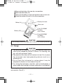
[3] NAME OF FUNCTION
3-1 Multimeter and Test Leads ………………………………004
3-2 Display ………………………………………………………005
[4] DESCRIPTION OF FUNCTIONS
4-1 Function Switch ……………………………………………006
4-2 Auto Power Off ……………………………………………006
4-3 Low Battery indication ……………………………………006
4-4 Measurement Function select ……………………………006
4-5 Range Hold …………………………………………………007
4-6 Data Hold ……………………………………………………007
4-7 Auto Lead Resistance Calibration ………………………007
4-8 Set Beeper Off………………………………………………008
4-9 RS232C Interface …………………………………………008
4-10 Data Logging Mode ………………………………………008
4-11 Words ………………………………………………………012
[5] MEASUREMENT PROCEDURE
5-1 Start-Up Inspection …………………………………………014
5-2 Voltage Measurement ……………………………………015
5-3 Frequency Measurement …………………………………016
5-4 Temperature Measurement ………………………………018
5-5 Capacitance Measurement and Testing Diode /
Resistance Measurement and Checking Continuity ……019
5-6 Current Measurement ……………………………………023
5-7 How to use Optional Product ……………………………026
PC520M_英 06.4.28 3:30 PM ページ 3
D-1034-141 SANWA PC520M(E)
[6] MAINTENANCE
6-1 Maintenance and Inspection ………………………………030
6-2 Calibration …………………………………………………030
6-3 Battery and Fuse Replacement …………………………030
6-4 Storage ………………………………………………………031
[7] AFTER-SALE SERVICE
7-1 Warranty and Provision ……………………………………032
7-2 Repair ………………………………………………………032
7-3 SANWA web site……………………………………………033
[8] SPECIFICATIONS
8-1 General Specification ………………………………………034
8-2 Measurement Range and Accuracy………………………036
PC520M_英 06.4.28 3:30 PM ページ 1
D-1034-141 SANWA PC520M(E)
[1]
SAFETY PRECAUTIONS
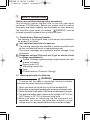
*Before use, read the following safety precautions.
This instruction manual explains how to use your new digital
multimeter PC520M safely. Before use, please read this manual
thoroughly, and, keep it together with the product for your reference.
The instruction given under the heading "
WARNING" must be
followed to prevent accidental burn or electrical shock.
1-1 Explanation of Warning Symbols
The meaning of the symbols used in this manual and attached to
the product is as follows.
: Very important instruction for safe use.
The warning messages are intended to prevent accidents such
as burn and electrical shock to operating personnel.
The caution messages are intended to prevent damage to the
instrument.
: Dangerous voltage (Take care not to get an electric shock
in voltage measurement.)
: Ground (Allowable applied voltage range between the input
terminal and earth.)
: Direct current (DC)
: Alternating current (AC)
: Fuse
: Double insulation (Protection Class )
1-2 Warning Instruction for Safe Use
WARNING
To ensure that the meter is used safely, be sure to observe
the instruction when using the instrument.
1. Never use meter on the electric circuit that exceed 6kVA.
2. Never apply an input signal exceeding the maximum rating input value.
3. Never use meter if the meter or test leads are damaged or broken.
4. Pay special attention when measuring the voltage of AC 33 Vrms
(46.7V peak) or DC 70V or and over avoid injury.
5.Never use meter for measuring the line connected with
equipment (i.e. motors) that generates induced or surge
voltage since it may exceed the maximum allowable voltage.
— 1 —
PC520M_英 06.4.28 3:30 PM ページ 2
D-1034-141 SANWA PC520M(E)
16. Never use uncased meter.
17. Be sure to use a fuse of the specified rating or type. Never use
a substitute of the fuse or never make a short circuit of the fuse.
18. When connecting and disconnecting the test leads, connect the
ground lead (black one) first. When disconnecting them, the
ground lead must be disconnected last.
19. Always keep your fingers below the finger guards on the
probe when making measurements.
10. Be sure to disconnect the test pins from the circuit when
changing the function.
11. Before starting measurement, make sure that the function and
range are properly set in accordance with the measurement.
12. Never use meter with wet hands or in a damp environment.
13. Do not use the device near an item of strong electromagnetic
generation or a charged item.
14. Never open tester case except when replacing batteries or
fuse. Do not attempt any alteration of original specifications.
15. To ensure safety and maintain accuracy, calibrate and check
the tester at least once a year.
16. The multimeter is restricted to indoor use only.
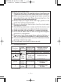
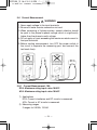
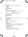
1-3 Overload protections
Functions
mV
V
Ω•
•
• Temp
Hz
µA•mA
A
Input Maximum rating
Maximum overload
terminals
input value
protection input
DC•AC 500mV
600VDC/AC rms
mV•V•Ω
DC•AC 1000V 1050V rms, 1450Vpeak
• •
Voltage and
•Temp
600VDC/AC rms
Current input
•Hz
•
prohibited
COM
Peak max : 300V
600VDC/AC rms
µA•mA
0.63A/500V Fuse
•
DC•AC 500mA
IR 200kA
COM
A
12.5A/500V Fuse
•
DC•AC 10A*
IR 20kA
COM
*10A continuous
— 2 —
PC520M_英 06.4.28 3:30 PM ページ 3
D-1034-141 SANWA PC520M(E)
[2] APPLICATION AND FEATURES
2-1 Applications
This instrument is portable digital multimeter designed for
measurement of weak current circuits. It plays an important role in
circuitry analysis by using additional functions as well as
measurements of small type communication equipment, electrical
home appliance, lighting voltage and batteries of various type.
2-2 Features
The instrument meets the requirements to Safety Standard
IEC61010.
The main unit case and the circuit board are made of fire
retarding materials.
Fuse protects the current function.
Large digit for easy readings
Fast Response; Digit: 5 times/sec., Bargraph: 60 times /sec.
Frequency measurement with 5 selectable sensitivity (Sine
RMS)
Built-in Memory up to 43,000 point
Capacitance measurement ranges are 50.00nF to 9999µF.
0.01Ω of resistance and 0.01mV of AC/DC resolution
RS-232C interface
AC coupling True RMS
Temperature measurement (K-type)
— 3 —
PC520M_英 06.4.28 3:30 PM ページ 4
D-1034-141 SANWA PC520M(E)
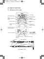
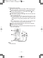
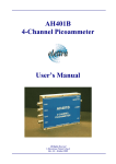
[3] NAME OF FUNCTIONS
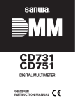
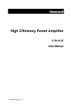
3-1 Multimeter and Test Leads
LCD Display
BACKWARD Button
FORWAD Button
CALL
START•PAUSE•STOP
Button
MEMORY
INTERVAL Button
DATA HOLD
Button
SELECT Button
RANGE HOLD
Button
FREQUENCY
SELECT Button
Holster
POWER Switch and
FUNCTION Switch
V•mV•Hz• •
•TEMP• •Ω
measuring terminal
A measuring terminal
µA•mA measuring
terminal
Test Pin
Common Input terminal
Test Probe(RED)
Finger Guards
Test Probe(BLACK)
Test Leads (TL-82)
— 4 —
Plug
PC520M_英 06.4.28 3:30 PM ページ 5
D-1034-141 SANWA PC520M(E)
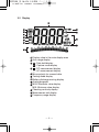
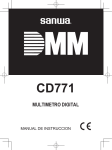
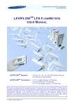
3-2 Display
Display value in the main display area
Auto range display
H : Data hold display
C : Capture mode display
: DC measurement display
: AC measurement display
Minus polarity for numeral data
Testing diode display
Battery discharge warring display
Analog bargraph
MAX: Maximum value display
MIN: Minimum value display
Checking continuty display
Measurement unit display
Frequency range display
— 5 —
PC520M_英 06.4.28 3:30 PM ページ 6
D-1034-141 SANWA PC520M(E)
[4] DESCRIPTION OF FUNCTIONS
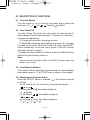
4-1 Function Switch
Turn this switch to turn on and off the power and to select the
functions of "V /V /mV/ • /Temp/Ω• /A/mA/µA".
4-2 Auto Power Off
The Auto Power Off mode turns the meter off automatically to
extend battery life after approximately 17 minutes of no activities.
Activities are specified as:
1) Changing sw position or pressing a button.
2) Significant measuring data readings of around 10% of range.
To wake up the meter from Auto Power Off, press the SELECT
button momentarily or turn the rotary switch to the OFF position
and then turn back on again.
To disable the Auto Power Off feature, press the RANGE button
while turning the function switch on.
Note:
Always turn the function switch to the OFF position when the
meter is not in use.
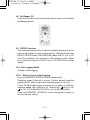
4-3 Low Battery Indication
If the internal battery has been consumed and the internal battery
drops below approx. 7V, BATTERY mark is shown in the display.
4-4 Measurement Function Select
When the SELECT button is pressed ( ), the functions change
as follows.
• In the case of mV, µA, mA and A, the modes change as:
.
• In the case of Ω/ , the modes change as:
Ω
Ω.
• In the case of / , the modes change as:
.
• In the case of Temp, the modes change as:
C F C. (C: , F: )
— 6 —
PC520M_英 06.4.28 3:30 PM ページ 7
D-1034-141 SANWA PC520M(E)
4-5 Range Hold
Press the RANGE button momentarily to set the manual range
mode then 'AUTO' disappears in the display. In manual range
mode, press the button again to step through the ranges. To
return to the auto mode, press the button for 1 sec. or more then
AUTO is shown.
Note:
Manual mode is not available in Hz measurement.
4-6 Data Hold
When the HOLD button is pressed, the data display at that time is
hold ('H' is shown on the display). The display will not changed
while the function is active. Press the button again to cancel the
function. ('H' on the display disappears.)
4-7 Auto Lead Resistance Calibration
When entering the 50Ω range manually by RANGE button for
high precision low resistance measurement, this feature will
prompt you to short the inputs for calibration. The display shows
"Shrt". Simply short the leads for about 3 seconds until the display
shows zero, then the resistance in the leads and in the internal
protection circuitry of the meter is compensated automatically.
The compensation value can be as much as 5Ω.
— 7 —
PC520M_英 06.4.28 3:30 PM ページ 8
D-1034-141 SANWA PC520M(E)
4-8 Set Beeper Off
Press the Hz button while turning the function switch on to disable
the Beeper feature.
4-9 RS232C Interface
The instrument equips with an optical isolated interface port at the
back of meter body for data communication. Optional accessories
KB-RS2 (RS232 cable), KB-USB2(USB cable) and PC Link or PC
Link Plus (software), are required for Data logging system. Refer
to an instruction manual in the PC Link or PC Link Plus for further
details.
4-10 Data Logging Mode
Prouder of data logging
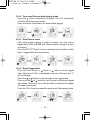
4-10-1 Select interval of data logging
Press the MEMORY INTERVAL button momentarily.
Sampling speed (interval) is shown. Factory default sampling
speed is t0.05, which means that sampling speed is 0.05 sec.
Press the
(or ) button momentarily to select a different
sampling speed from 0.05s(0.2s for Temp•Ω• •
,0.4s for Hz,
for 1s), 1s,20s,40s,60s,120s,240s, up to the slowest 480s.
Press the MEMORY INTERVAL button momentarily again to
confirm the new setting.
— 8 —
PC520M_英 06.4.28 3:30 PM ページ 9
D-1034-141 SANWA PC520M(E)
Note:
• Data logging mode is not available for 50.00µF, 500.0µF and
9999µF range because of slow response for large capacitance.
• The sampling speed cannot be set when the data logging is
running.
Please set the sampling speed before starting the data
logging, or pause the data if you want to alter the sampling
speed setting during data logging.
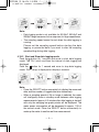
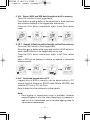
4-10-2 Start and Stop data logging mode
Push the button for 1 second and more to start data logging
mode. The 'Strt' (start) and then the interval of data logging are
displayed.
Push the
button for 1 second and more to stop data logging
mode. 'StoP' (stop) is displayed on display a moment.
1S
1S
Note:
• Press the SELECT button momentarily to display the measured
data and the number of logged data item alternatively.
• When a sampling speed of 20s or longer is selected, the meter
will intelligently enter a standby mode between data logging
measurements (approx. 4.5 minutes after data logging is started)
with only the swinging bar-graph pointer will be displayed. The
meter power consumption will be decreased to approx. 1/30 of
the normal mode. Press the SELECT button momentarily to
wake up the meter to see the real time measurement.
— 9 —
PC520M_英 06.4.28 3:30 PM ページ 10
D-1034-141 SANWA PC520M(E)
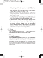
4-10-3 Pause and Resume data logging mode
Press the
button momentarily to pause. The LCD annunciator
'H' will be flashing when paused.
Press the button momentarily to resume data logging.
4-10-4 Data Review mode
After exiting data logging or when in pause, you can review
logged data, MAX and MIN and inflection points though out builtin memory.
Press the SELECT button to show readings and a number of data
item of logged data item alternatively.
4-10-5 Recall logged data
Press the CALL button or
button or
button to recall logged
data. Indication of CALL is displayed a moment. During recall, 'C'
will be flashing.
Press the or button to step throughout the logged data.
Press and hold or button for fast forward or backward logged
data review. When the first or the last data is reached, the beeper
will beep continuously.
Press the CALL button momentarily again to exit Data review mode.
— 10 —
PC520M_英 06.4.28 3:30 PM ページ 11
D-1034-141 SANWA PC520M(E)
4-10-6 Search MAX and MIN data throughout built-in memory
Press CALL button to recall logged data.
Press both of
and
button at the same time to show maximum
and minimum readings of the logged date alternatively.
Press the CALL button momentarily again to exit Data review
mode.
4-10-7 Search inflection points though out built-in memory
Press the CALL button to recall logged data.
Press the or button while press and hold the HOLD button to
show inflection points of the logged data one by one.
Press the CALL button momentarily again to exit Data review
mode.
MAX or MIN will be flashing to indicate an upward or downward
inflection points.
H
4-10-8 Download logged data to PC
Logged data in Built-in memory can be downloading to PC
through optional accessory RS232 cable (Model KB-RS2) and
software (PC Link or PC Link Plus).
Refer to help file in the software for further details.
Note:
• Data logging for capacitance range is available. However
response speed is too slow when capacitance to measure is
high so it is not recommend you to use data logging mode for
capacitance measurement.
— 11 —
PC520M_英 06.4.28 3:30 PM ページ 12
D-1034-141 SANWA PC520M(E)
• When the logged data item number exceeded 9999 (where
available), the bar-graph will also be used to indicate the
most significant digit of the item number in the order of
10000. That is 1 = 10000, 2 = 20000, ... etc.
• When the memory is full, the data logging mode will be
stopped automatically, and the instrument will then enter the
Auto Power Off mode.
• To guarantee the accuracy of every logged data, the
instrument will stop the data logging mode when the battery
is low, and goes back to the normal measuring mode.
• The data will be stored to the non-volatile memory shortly
after every measurement to maximize data safety. However,
the end-of-data sign can only be stored after the data logging
is finished. Therefore, always "StoP" the data logging
function before switching off the instrument. After the data
logging is finished, you can switch off the instrument for
transportation, storage, or even changing battery.
4-11 Words
Analog Bargraph
The analog bargraph provides a visual indication of
measurement like a traditional analog meter needle.
AC Sensing
[AC coupling True RMS]
When measurement is taken by true r.m.s., the measurement
value of input signal becomes the scales of the signal power
and therefore provide more effective values than those
obtained by average value detection. This multimeter implies
this true RMS circuit, which enables measurement of sine wave
and non-sinusoidal waves like square wave and triangular
wave in r.m.s.
— 12 —
PC520M_英 06.4.28 3:30 PM ページ 13
D-1034-141 SANWA PC520M(E)
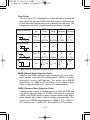
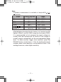
Crest Factor
The crest factor (CF) is expressed by a value obtained by dividing the
peak value of the signal by its RMS value. Most common waveforms such
as sine wave and triangular wave have a relatively low crest factor. The
voltages and crest factors of typical waveforms are shown in the table.
Input Waveform
Sine Wave
Vp
RMS
Vrms
Average
CF
Form Factor
Vavg Vp/Vrms Vrms/Vavg
Vp
2Vp
――
――
2
2
π
=1.414Vrms =0.707Vp =0.637Vp =1.414
Vrms・ 2
π
0
Peak
Vp
2π
π
――
2 2
=1.111
Square Wave
Vp
Vp
0
π
Triangular Wave
Vp
0
π
2π
Vp
Vp
Vp
――
――
3
2
=1.732Vrms =0.577Vp =0.5Vp
Vp
τ
Vp
Vrms・ 3
Puls
0
Vp
1
1
2π
2π
τ
―― •Vp
2π
τ
―― •Vp
2π
=1.732
2
――
3
=1.155
2π
――
τ
2π
――
τ
3
Please note the measurement should be taken at the crest factor below 3.
NMRR (Normal Mode Rejection Ratio)
NMRR is the DMM's ability to reject unwanted AC noise effect,
which causes inaccurate DC measurements. NMRR is typically
specified in terms of dB (decibel). This series has a NMRR
specification of >60dB at 50 and 60Hz, which means a good
ability to reject the effect of AC noise in DC measurements.
CMRR (Common Mode Rejection Ratio)
Common mode voltage is voltage present on both the COM and
VOLTAGE input terminals of a DMM, with respect to ground.
CMRR is the DMM's ability to reject common mode voltage effect,
which causes digit rattle or offset in voltage measurements. This
series has a CMRR specifications of >60dB at DC to 60Hz in
ACV function; and >120dB at DC, 50 and 60Hz in DCV function.
— 13 —
PC520M_英 06.4.28 3:30 PM ページ 14
D-1034-141 SANWA PC520M(E)
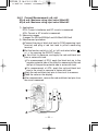
[5] MEASUREMENT PROCEDURE
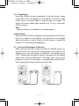
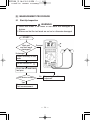
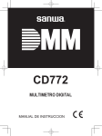
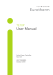
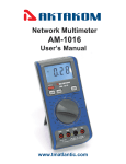
5-1 Start-Up Inspection
WARNING
1. Never use meter if the meter or test leads are damaged or
broken.
2. Make sure that the test leads are not cut or otherwise damaged.
START
Main unit
and test leads
damaged?
Damaged
No damaged
Check continuty of test
leads
Set the function to "
".
Short the red and black
test pins.
The buzzer sounds?
No Stop using it and have
it repaired.
Yes
No problem.
Start measurement.
— 14 —
PC520M_英 06.4.28 3:30 PM ページ 15
D-1034-141 SANWA PC520M(E)
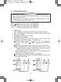
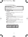
5-2 Voltage Measurement
WARNING
1. Never apply an input signal exceeding the maximum rating input value.
2. Be sure to disconnect the test pins from the circuit when
changing the function.
3. Always keep your fingers behind the finger guards on the
probe when making measurements.
DCmV:
DCV:
ACmV:
ACV:
Maximum
Maximum
Maximum
Maximum
rating
rating
rating
rating
input
input
input
input
value
value
value
value
500mVDC
1000VDC
500mVAC
1000VAC
1) Applications
DCV: Voltage of the battery and DC circuit are measured.
ACV: Sine wave AC voltage such as lighting voltage is measured.
2) Measuring ranges
6 ranges from 50.00mV to 1000V
3) Measurement procedure
Connect the plug of black test lead to COM terminal and
plug of red test lead to mV or V m terminal.
Set the function switch to 'V ' or 'V ' or 'mV'. (When set
the 'mV', select either '
' or '
' by pressing the SELECT
button.)
Apply the red and black test pins to the circuit to measure.
For measurement of DCV, apply the black test pin to the
negative potential side of the circuit to measure and the
red test pin to the positive potential side.
For measurement of ACV, apply the red and black test
pins to the circuit to measure.
The reading of Voltage is shown in the display.
After measurement, release the red and black test pins from
the object measured.
— 15 —
PC520M_英 06.4.28 3:30 PM ページ 16
D-1034-141 SANWA PC520M(E)
5-3 Frequency Measurement
WARNING
1. Never apply an input signal exceeding the maximum rating
input value.
2. Be sure to disconnect the test pins from the circuit when
changing the function.
3. Always keep your fingers behind the finger guards on the
probe when making measurements.
1) Application
Frequency of an AC circuit is measured.
2) Measuring ranges
10Hz to 125.0kHz (Auto range)
3) Measurement procedure
Connect the plug of black test lead to COM measuring input
terminal and plug of red test lead to Hz measuring terminal.
Set the function switch to V.
Press the Hz button momentarily to activate or to exit Hz.
Apply the red and black test pins to an object to measure.
Read the value in the display.
After measurement, release the red and black test pins from
the object measured.
— 16 —
PC520M_英 06.4.28 3:30 PM ページ 17
D-1034-141 SANWA PC520M(E)
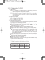
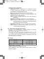
Note:
Frequency measurement is available at temp/mA/Ω/ / /
functions.
Range
Sensitivity (Sine Wave)
Range
500mV
300mV
10Hz - 125kHz
5V
2V
10Hz - 125kHz
50V
20V
10Hz - 20kHz
500V
80V
10Hz - 1kHz
1000V
300V
10Hz - 1kHz
Ω/ / /
300mV
10Hz - 125KHz
µA/mA, A
10% F.S.
10Hz - 125kHz
Input sensitivity varies automatically with function range
selected before activating the Hz function. mV function has the
highest (300mV), and the 1000V range has the lowest (300V).
It is recommended to first measure the signal voltage (or
current) level then activates the Hz function in that voltage (or
current) range to automatically set the most appropriate trigger
level. To select another trigger level manually, press the
RANGE button momentarily. If the Hz reading becomes
unstable, select lower sensitivity to avoid electrical noise. If the
reading shows zero, select higher sensitivity.
— 17 —
PC520M_英 06.4.28 3:30 PM ページ 18
D-1034-141 SANWA PC520M(E)
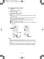
5-4 Temperature Measurement
1) Application
Temperature is measured.
2) Measuring ranges
Range from -50 to 1000
3) Measurement procedure
Input the -plug to COM input terminal and the +plug to
Temp terminal.
Set the function switch to 'Temp' and select either ' ' or ' '
by pressing the SELECT switch.
Apply the sensor of K-250PC to an object to measure.
Read the value in the display.
After measurement, release the sensor from the object
measured.
Note:
Be sure to insert temperature probe with correct + - polarities.
K-250PC (Standard Accessory) can be measured from -50 to
250
You can also use a K-type adapter K-AD (Optional accessory)
to adapt other standard K type mini plug temperature probes.
— 18 —
PC520M_英 06.4.28 3:30 PM ページ 19
D-1034-141 SANWA PC520M(E)
5-5 Capacitance Measurement and Testing Diode/
Resistance Measurement and Checking Continuity
CAUTION
Discharge the capacitance before measurement.
5-5-1 Capacitance Measurement
1) Application
Measures capacitance of condensor.
2) Measuring ranges
6 ranges from 50.00nF to 9999µF
3) Measurement procedure
Connect the plug of black test lead to COM measuring input
terminal and plug of red test lead to
measuring terminal.
Set the function switch to ' / ' and select ' ' by pressing
the SELECT button.
Apply the red and black test pins to an object to measure.
Read the value in the display.
After measurement, release the red and black test pins from
the object measured.
Note:
While data communication to PC, Capacitance readout can be
sent to PC correctly up to 500.0µF range because of low
response speed for large capacitance measurement.
While data logging mode without PC for PC520M, Capacitance
can be logged correctly up to 5.000µF range because of low
response speed for large capacitance measurement.
— 19 —
PC520M_英 06.4.28 3:30 PM ページ 20
D-1034-141 SANWA PC520M(E)
5-5-2 Testing Diode
1) Application
The quality of diodes is tested.
2) How to use
Connect the plug of black test lead to COM measuring input
terminal and plug of red test lead to measuring terminal.
Set the function switch to ' / ' and select ' ' by pressing
the SELECT switch.
Apply the black test pins to the cathode of the diode and the
red test pin to the anode.
Check reading for judgment of good or defective.
A zero reading indicates a shorted diode (defective).
An OL indicates an open diode (defective).
Apply the red test pins to the cathode of the diode and the
black test pin to the anode
The display shows OL, if diode is good. Any other
readings indicated the diode is resistive or shorted
(defective).
After measurement, release the red and black test pins from
the object measured.
Note:
Release voltage of the input terminals is about <3.5V.
— 20 —
PC520M_英 06.4.28 3:30 PM ページ 21
D-1034-141 SANWA PC520M(E)
5-5-3 Resistance Measurement
1) Applications
Resistance of resistors and circuits is measured.
2) Measuring ranges
7 ranges from 50.00Ω to 50.00MΩ.
3) Measurement procedure
Connect the plug of black test lead to COM input terminal
and plug of red test lead to Ω input terminal.
Set the function switch to 'Ω/ ' and select 'Ω' by pressing
the SELECT button.
Apply the red and black test pins to an object to measure.
The reading is shown in the display.
After measurement, release the red and black test pins from
the object measured.
Note:
When entering 50Ω range, Auto Lead Resistance Calibration
feature activate. See 4-7.
If measurement is likely to be influenced by noise, shield the
object to measure with negative potential (COM).
If a finger touches a test pin during measurement, measurement
will be influenced by the resistance in the human body and
result in measurement error.
Release voltage of the input terminals is about <1.3VDC.
(<3VDC for 50Ω & 500Ω ranges)
— 21 —
PC520M_英 06.4.28 3:30 PM ページ 22
D-1034-141 SANWA PC520M(E)
5-5-4 Checking Continuity
1) Application
Checking the continuity of wiring and selecting wires.
2) How to use
Connect the plug of black test lead to COM measuring input
terminal and plug of red test lead to
measuring terminal.
Set the function switch to 'Ω/ ' and select ' ' by pressing
the SELECT button.
Apply the red and black test pins to a circuit or conductor to
measure.
The continuity can be judged by whether the buzzer sounds
or not.
After measurement, release the red and black test pins from
the object measured.
Note:
Threshold: between 20Ω and 120Ω.
Response time: <100µs
— 22 —
PC520M_英 06.4.28 3:30 PM ページ 23
D-1034-141 SANWA PC520M(E)
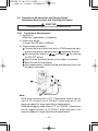
5-6 Current Measurement
WARNING
1. Never apply voltage to the input terminals.
2. Be sure to make a series connection via load.
3. When measuring a 3-phase system, special attention should
be paid to the phase-to-phase voltage which is significantly
higher than the phase to earth voltage.
4. Do not apply an input exceeding the maximum rated current to
the input terminals.
5. Before starting measurement, turn OFF the power switch of
the circuit to separate the measuring part, and connect the
test leads firmly.
5-6-1 Current Measurement: 10A
DCA: Maximum rating input value 10ADC
ACA: Maximum rating input value 10AAC
1) Applications
DCA: Current in batteries and DC circuits is measured.
ACA: Current in AC circuits is measured.
2) Measuring ranges
2 ranges for 5.000A, 10.00A
— 23 —
PC520M_英 06.4.28 3:31 PM ページ 24
D-1034-141 SANWA PC520M(E)
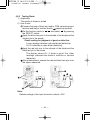
3) Measurement procedure
Connect the plug of black test lead to COM measuring input
terminal and plug of red test lead to A measuring terminal.
Set the function switch to 'A' and select either ' ' or ' '
by pressing the SELECT button.
In the circuit to measure and apply the red and black test
pins in series with load.
For measurement of DCA, apply the black test pin to the
negative potential side of the circuit to measure and the
red test pin to the positive potential side in series with
load.
For measurement of ACA, apply the red and black test
pins to the circuit to measure in series with load.
Apply the red and black test pins to the circuit to measure.
Read the value in the display.
After measurement, remove the red and black test pins from
the circuit measured.
•
Note:
10A continuous
— 24 —
PC520M_英 06.4.28 3:31 PM ページ 25
D-1034-141 SANWA PC520M(E)
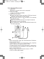
5-6-2 Current Measurement: µA, mA
DCµA, mA: Maximum rating input value 500mADC
ACµA, mA: Maximum rating input value 500mAAC
1) Applications
DCA: Current in batteries and DC circuits is measured.
ACA: Current in AC circuits is measured.
2) Measuring ranges
4 ranges for 400.0µA/4000µA and 40.00mA/400.0mA
3) Measurement procedure
Connect the plug of black test lead to COM measuring input
terminal and plug of red test lead to µA/mA measuring
terminal.
Set the function switch to 'µA' or 'mA' and select either ' '
or ' ' by pressing the SELECT button.
In the circuit to measure, and apply the red and black test
pins in series with load.
For measurement of DCA, apply the black test pin to the
negative potential side of the circuit to measure and the red
test pin to the positive potential side in series with load.
For measurement of ACA, apply the red and black test
pins to the circuit to measure in series with load.
Apply the red and black test pins to the circuit to measure.
Read the value on the display.
After measurement, remove the red and black test pins from
the circuit measured.
•
— 25 —
PC520M_英 06.4.28 3:31 PM ページ 26
D-1034-141 SANWA PC520M(E)
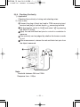
5-7 How to use Optional Product
WARNING
1. Never apply an input signal exceeding the maximum rating
input value of optional products.
2. Be sure to disconnect the test pins from the circuit when
changing the function.
5-7-1 Clamp probe: CL-20D
1) Applications
It is suitable for measurement of alternating current in electric
equipment and power supplies.
2) Measuring ranges
2 ranges for 20A, 200A
3) Measurement procedure
Connect the black plug to COM measuring terminal, and the
red plug to V measuring terminal.
Set the function to 'V' and select AC with the SELECT
button.
Press the RANGE button to hold the 5V range.
Open the clamp part, have electric wire (one line) clamped,
and close the clamp part completly.
Read the value on the display. *1
After measurement, open the clamp part, and release clamp
probe from the electric wire.
*1: Read the value on the display as follows
Measuring range
20A
200A
Multiplier
x10
x100
— 26 —
Unit
A
A
PC520M_英 06.4.28 3:31 PM ページ 27
D-1034-141 SANWA PC520M(E)
5-7-2 Clamp probe: CL-22AD
1) Applications
ACA: It is suitable for measurement of alternating current in
electric equipment and power supplies.
DCA: An electric current of electric circuit of a car and a
consumption electric current of direct current apparatus
are measured.
2) Measuring ranges
ACA: 2 ranges for 20A, 200A
DCA: 2 ranges for 20A, 200A
3) Measurement procedure
Connect the black plug to COM measuring terminal, and the
red plug to mV measuring terminal.
Set the function to 'mV' and select either '
' or '
' by
pressing the SELECT button.
Press the RANGE button to hold the 500mV range.
Select either 20A or 200A by selector knob of clamp meter.
The zero point varies when the DCA is measured, so be
sure to check that the multimeter indicates zero. If not
zero, adjust the indication to the zero point by turning the
Zero adjuster (0ADJ).
Open the clamp part, have electric wire (one line) clamped,
and close the clamp part completly.
Read the value on the display. *2
After measurement, open the clamp part and release clamp
probe from the electric wire.
*2: Read the value on the display as follows
Measuring range
20A
200A
Multiplier
x1/10
x1
— 27 —
Unit
A
A
PC520M_英 06.4.28 3:31 PM ページ 28
D-1034-141 SANWA PC520M(E)
5-7-3 Clamp probe: CL33DC
1) Applications
An electric current of electric circuit of a car and a
consumption electric current of direct current apparatus are
measured.
2) Measuring ranges
2 ranges for 30A, 300A
3) Measurement procedure
Connect the black plug to COM measuring terminal, and the
red plug to mV measuring terminal.
Set the function to 'mV' and select either '
' or '
' by
pressing the SELECT button.
Press the RANGE button to hold the 500mV range.
Select either 30A or 300A with selector knob of clamp
meter.
The zero point varies when the DCA is measured, so be
sure to check that the multimeter indicates zero. If not
zero, adjust the indication to the zero point by turning the
Zero adjuster (0ADJ).
Open the clamp part, have electric wire (one line) clamped,
and close the clamp part completly.
Read the value on the display. *3
After measurement, open the clamp part and release clamp
probe from the electric wire.
*3: Read the value on the display as follows
Measuring range
Multiplier
Unit
30A
x1/10
A
300A
x1
A
— 28 —
PC520M_英 06.4.28 3:31 PM ページ 29
D-1034-141 SANWA PC520M(E)
5-7-4 Temperature probe: T300-PC
1) Applications
To measure temperature from -50 to 300
2) Measuring ranges
Range of -50 to 300
3) Measurement procedure
Connect the black plug to COM measuring terminal and the
red plug to Ω measuring terminal.
Set the function to 'Ω'.
Press the RANGE button to hold the 5kΩ range.
Apply the sensor to an object to measure.
Read the value on the display. *4
After measurement, release the sensor from the object
measured.
*4: The value on the display of DMM shows a resistance
value indicate. Please read the value of measuring
window of PC Link.
— 29 —
PC520M_英 06.4.28 3:31 PM ページ 30
D-1034-141 SANWA PC520M(E)
[6] MAINTENANCE
WARNING
1. This section is very important for safety. Read and understand the
following instruction fully and maintain your instrument properly.
2. The instrument must be calibrated and inspected at least once
a year to maintain the safety and accuracy.
6-1 Maintenance and Inspection
1) Appearance
• Is the appearance not damaged by falling, etc?
2) Test leads
• Is the cord of the test leads not damaged?
• Is the core wire not exposed at any place of the test leads?
NOTE:
• If the built-in fuse is blown, only the current measurement
does not work.
• Make sure that the test leads are not cut, referring to the section 5-1.
6-2 Calibration
The manufacturer may conduct the calibration and inspection. For
more information, please contact the manufacturer.
6-3 Battery and Fuse Replacement
WARNING
1. If the rear case or the battery lid is removed when input is applied
to the input terminals, you may get electrical shock. Before
starting the work, always make sure that no input is applied.
2. Before starting the work, be sure to turn OFF the main power
and release the test leads from the circuit.
3. Be sure to use a fuse of the specified rating or type. Never use
a substitute of the fuse or never make a short circuit of the fuse.
Factory-preinstalled built-in battery
A battery for monitoring is preinstalled before shipping,
therefore it may run down sooner than the battery life specified
in the instruction manual.
The "battery for monitoring" is a battery to inspect the functions
and specifications of the product.
— 30 —
PC520M_英 06.4.28 3:31 PM ページ 31
D-1034-141 SANWA PC520M(E)
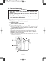
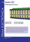
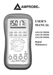
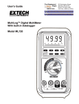
Remove the battery lid screw by a screwdriver.
Removed the battery lid.
Take out the battery or fuse and replace it with a new one.
Attach the battery lid and fix it by the screwdriver.
Battery lid screw
Battery lid
Rear case
Fuse 12.5A/500V
IR: 20kA
ø6.3 x 32mm
Battery (9V)
Fuse 0.63A/500V
IR: 200kA
ø6.3 x 32mm
CAUTION
Set a battery carefully being sure to observe the correct polarities.
6-4 Storage
CAUTION
1.The panel and the case are not resistant to volatile solvent and
must not be cleaned by thinner or alcohol. For cleaning, use
dry, soft cloth and wipe it lightly.
2.The panel and the case are not resistant to heat. Do not place
the instrument near heat-generating devices (such as a
soldering iron).
3. Do not store the instrument in a place where it may be
subjected to vibration or from where it may fall.
4. For storing the instrument, avoid hot, cold or humid places or
places under direct sunlight or where condensation is anticipated.
Following the above instructions, store the instrument in good
environment. (See 8-1)
— 31 —
PC520M_英 06.4.28 3:31 PM ページ 32
D-1034-141 SANWA PC520M(E)
[7] AFTER-SALE SERVICE
7-1 Warranty and Provision
Sanwa offers comprehensive warranty services to its end-users
and to its product resellers. Under Sanwa's general warranty
policy, each instrument is warranted to be free from defects in
workmanship or material under normal use for the period of one
(1) year from the date of purchase.
This warranty policy is valid within the country of purchase only,
and applied only to the product purchased from Sanwa authorized
agent or distributor.
Sanwa reserves the right to inspect all warranty claims to
determine the extent to which the warranty policy shall apply.
This warranty shall not apply to fuses, disposables batteries, or
any product or parts, which have been subject to one of the
following causes:
1. A failure due to improper handling or use that deviates from
the instruction manual.
2. A failure due to inadequate repair or modification by people
other than Sanwa service personnel.
3. A failure due to causes not attributable to this product such as
fire, flood and other natural disaster.
4. Non-operation due to a discharged battery.
5. A failure or damage due to transportation, relocation or
dropping after the purchase.
7-2 Repair
Customers are asked to provide the following information when
requesting services:
1. Customer name, address, and contact information
2. Description of problem
3. Description of product configuration
4. Model Number
5. Product Serial Number
6. Proof of Date-of-Purchase
7. Where you purchased the product
— 32 —
PC520M_英 06.4.28 3:31 PM ページ 33
D-1034-141 SANWA PC520M(E)
1) Prior to requesting repair, please check the following:
Capacity of the built-in battery, polarity of installation and
discontinuity of the test leads.
2) Repair during the warranty period:
The failed meter will be repaired in accordance with the
conditions stipulated in 7-1 Warranty and Provision.
3) Repair after the warranty period has expired:
In some cases, repair and transportation cost may become
higher than the price of the product. Please contact Sanwa
authorized agent / service provider in advance.
The minimum retention period of service functional parts is 6
years after the discontinuation of manufacture. This retention
period is the repair warranty period. Please note, however, if
such functional parts become unavailable for reasons of
discontinuation of manufacture, etc., the retention period may
become shorter accordingly.
4) Precautions when sending the product to be repaired
To ensure the safety of the product during transportation,
place the product in a box that is larger than the product 5
times or more in volume and fill cushion materials fully and
then clearly mark "Repair Product Enclosed" on the box
surface. The cost of sending and returning the product shall
be borne by the customer.
7-3 SANWA web site
http://www.sanwa-meter.co.jp
E-mail: [email protected]
— 33 —
PC520M_英 06.4.28 3:31 PM ページ 34
D-1034-141 SANWA PC520M(E)
[8] SPECIFICATIONS
8-1 General Specification
Display:
3-5/6 digits 5000 counts LCD display
Update Sampling Rate:
Digital data: 5 times / sec nominal
52 segments bar graph: 60 times / sec nominal
Low Battery Indication:
Below approx. 7V
Operating Temperature:
0 to 35 , 0-80% R.H.; 35 to 50 , 0-70% R.H.
Storage Temperature:
-20 to 60 , 80% R.H. (With battery removed)
Altitude:
Operating below 2000m
Temperature Coefficient:
Nominal 0.15x(specified accuracy)/ @(0 -18 or 28
or otherwise specified
— 34 —
-50
),
PC520M_英 06.4.28 3:31 PM ページ 35
D-1034-141 SANWA PC520M(E)
Power Supply:
9V alkaline battery; NEDA1604A, 6LR61 or IEC6LF22
Sensing:
True RMS
Auto Power Off Timing:
Idle for 17 minutes
Safety:
IEC61010-1 (EN61010-1) 2nd (2001):
V/ /Ω• / /Hz : CAT
for 600V DC & AC, and CAT
for
1kV DC & AC
µA•mA
: CAT 500V AC & 300V DC
A
: CAT 500V AC & 300V DC
Transient Protection:
6.5kV (1.2/50µs surge)
Pollution degree:
2
E.M.C.:
Meets EN55022 (1994/A1; 1995/Class B) and EN50082-1 (1992)
Power Consumption:
2.6mA Typical
Dimension:
179(H) x 87(W) x 55(D) mm with holster
Weight:
320 mg, 460 mg with holster
Accessories:
Test leads (TL-82), Alligator Clip: CL-13, Holster (H-50), Battery
(installed), Instruction manual, K-type thermocouple (K-250PC)
Optional Accessories:
RS232 cable: KB-RS2
Software: PC Link, PC Link Plus
K-type adapter: K-AD
Temperature Probe: T-300PC (Platinic thin film)
Clamp Probe: CL-20D, CL-22AD, and CL33DC
— 35 —
PC520M_英 06.4.28 3:31 PM ページ 36
D-1034-141 SANWA PC520M(E)
OVERVOLTAGE CATEGORY
• Equipment of CAT is equipment for connection to circuits
in which measures are taken to limit the transient
overvoltages to an appropriate low level.
Note: Examples include protected electronic circuits.
• Equipment of CAT is energy-consuming equipment to be
supplied from the fixed installation.
Note: Examples include household, office, and laboratory
appliances.
• Equipment of CAT is equipment in fixed installations.
Note: Examples include switches in the fixed installation and
some equipment for industrial use with permanent
connection to the fixed installation.
• Equipment of CAT
is for use at the origin of the installation.
Note: Examples include electricity meters and primary overcurrent protection equipment.
8-2 Measurement Range and Accuracy
Accuracy is ±(% reading digits + number of digits) or otherwise
specified, at 23 ±5 & less than 75% R.H.
TRUE RMS ACV & ACA accuracies are specified from 5 % to 100
% of range or otherwise specified, crest factor <3:1 at full scale &
<6:1 at half scale, and with frequency component within the
specified frequency bandwidth
DC Voltage
RANGE
Accuracy
50.00 mV
0.12% rdg + 2dgt
500.0 mV
0.06% rdg + 2dgt
5.000V, 50.00V, 500.0V, 1000V
0.08% rdg + 2dgt
NMRR:>60dB @ 50/60Hz
CMRR:>120dB @ DC, 50/60Hz, Rs=1kΩ
Input Impedance: 10MΩ, 16pF nominal (44pF nominal for 50mV
& 500mV ranges)
— 36 —
PC520M_英 06.4.28 3:31 PM ページ 37
D-1034-141 SANWA PC520M(E)
AC Voltage
RANGE
50Hz - 60Hz
Accuracy
50.00mV, 500.0mV, 5.000V,
50.00V, 500.0V, 1000V
40Hz - 500Hz
50.00mV, 500.0mV
5.000V, 50.00V, 500.0V
1000V
Up to 20kHz
50.00mV, 500.0mV
5.000V, 50.00V, 500.0V
1000V
CMRR:>60dB @ DC to 60Hz, Rs=1kΩ
Input Impedance: 10MΩ, 16pF nominal
& 500mV ranges)
**Specified from 30% to 100% of range
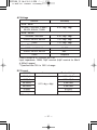
DC Current
RANGE
500.0µA
5000µA
50.00mA
500.0mA
5.000A
10.00A*
Accuracy
0.2% rdg + 4dgt
*10A continuous
— 37 —
0.5% rdg + 3dgt
0.8% rdg + 3dgt
1.0% rdg + 4dgt
1.2% rdg + 4dgt
0.5dB**
3dB**
Unspec'd
(44pF nominal for 50mV
Burden Voltage
0.15mV/µA
0.15mV/µA
3.3mV/mA
3.3mV/mA
0.03V/A
0.03V/A
PC520M_英 06.4.28 3:31 PM ページ 38
D-1034-141 SANWA PC520M(E)
AC Current
RANGE
50Hz - 60Hz
500.0µA
5000µA
50.00mA
500.0mA
5.000A
10.00A*
40Hz - 1kHz
500.0µA
5000µA
50.00mA
500.0mA
5.000A
10.00A*
*10A continuous
Accuracy
0.6% rdg +3dgt
1.0% rdg +3dgt
0.6% rdg +3dgt
0.8% rdg +4dgt
1.0% rdg +4dgt
Burden Voltage
0.15mV/µA
0.15mV/µA
3.3mV/mA
3.3mV/mA
0.03V/A
0.03V/A
0.15mV/µA
0.15mV/µA
3.3mV/mA
3.3mV/mA
0.03V/A
0.03V/A
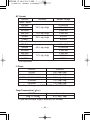
Ω Ohms
RANGE
Accuracy
50.00Ω
0.4% rdg+ 6dgt
500.0Ω
0.2% rdg+ 3dgt
5.000kΩ, 50.00kΩ, 500.0kΩ
0.2% rdg+ 2dgt
5.000MΩ
1.0% rdg+ 3dgt
50.00MΩ
1.5% rdg+ 5dgt
Open Circuit Voltage : <1.3VDC (<3VDC for 50Ω& 500Ωranges)
Temp Temperature (
&
)
RANGE
Accuracy*
-50 TO 1000
0.3% rdg + 3dgt
*K type thermocouple range & accuracy not included
— 38 —
PC520M_英 06.4.28 3:31 PM ページ 39
D-1034-141 SANWA PC520M(E)
Hz Frequency
Function
Sensitivity (Sine RMS)
mV
300mV
5V
2V
50V
20V
500V
80V
1000V
300V
Ω, , ,
300mV
µA, mA, A
10% F.S.
Accuracy: 0.01% rdg + 2dgt
Range
10Hz - 125kHz
10Hz - 125kHz
10Hz - 20kHz
10Hz - 1kHz
10Hz - 1kHz
10Hz - 125kHz
10Hz - 125kHz
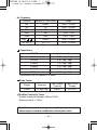
Capacitance
RANGE
50.00nF
500.0nF
5.000µF
50.00µF
500.0µF
9999µF
*Accuracies with film capacitor or better
Accuracy*
0.8% rdg + 3dgt
0.8% rdg + 3dgt
1.0% rdg + 3dgt
2.0% rdg + 3dgt
3.5% rdg + 5dgt
5.0% rdg + 5dgt
Diode Tester
Range
Accuracy
Test Current
(Typical)
Open Circuit
Voltage
2.000V
1% rdg+1dgt
0.8mA
<3.5 VDC
Audible Continuity Tester
Audible threshold: between 20Ωand 120Ω.
Response time: < 100µs
Specifications and external appearance of the product described
above may be revised for modification without prior notice.
— 39 —
PC520M_英 06.4.28 3:31 PM ページ 40
D-1034-141 SANWA PC520M(E)
MEMO
PC520M_英 06.4.28 3:31 PM ページ 41
D-1034-141 SANWA PC520M(E)
MEMO
PC520M_英 06.4.28 3:31 PM ページ 42
D-1034-141 SANWA PC520M(E)
SANWA ELECTRIC
INSTRUMENT CO.,LTD.
Dempa Bldg,Sotokanda2-Chome
Chiyoda-Ku,Tokyo,Japan
4
06.05
B