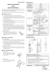
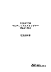
1
The MP-981 is a magneto-type detector using a hall element which is suitable for rpm measurement from ultra low speed to high speeds.
Magneto-type detectors use an internal hall element, a permanent magnet,
DC amplifier, and voltage regulator and respond to flux (i.e., the resistance
value changes in response to flux changes), so that a rectangle waveform is
derivable from ultra low speed all the way through high speeds.
In addition, a signal indicator is provided in spite of the detector s compact
design, making verification of operation and mounting position possible.
WARNING
② Detection Gear
The following type of detection gear should be used.
・Gear type
:Involute or equivalent
・Modulus
:0.5 〜 3
・Tooth width :3 mm or greater
・Material
:Strong magnetic properties
(e.g., S45C, SS400, etc.)
Machined
diameter
Fig.2
③ Positioning
Fig.3
The detector must be positioned
Detection gear
properly with respect to the detection gear. As shown in Fig.3 (1) this
(1)
is simplified by the use of the positioning mark ( ) . A positioning Mounting Fixture
Positioning mark
mark is located on both the top and
bottom of the detector. And the ends
(2)
of the teeth of the detection gear
should be positioned to roughly the
center between these marks.
Mouting should also be done so that the gear shaft is perpendicular to the
detector.
As shown in Fig. 3 (2), the center of the gear should be aligned with the
center of the detector. If these are not aligned properly, the detection distance will become short and, depending upon the dirsction of rotation of the
gear, the output signal could be cut off at times. Therefore, sufficient care is
required when mounting to obtain an accurate, proper mount.
IND
② The width of output pulse is not always same at the direction of the
revolution, CW or CCW.
▲
Fig.4
the direction
of CW
Example
CW
CCW
● Temperature:25
2.0
1.0
0.5
■USE
● Names of the Parts ( Refer to Fig. 1)
Fig.1
Indicator
1
-98
MP
Input/output connector
1
2
3
● Modulus:1
● r/min:1〜20,000
(60
P/R)
100 %
80 %
0
Mounting nut
0.5
Gears of modulus greater than 1 should be used as lower values of modulus
will greatly effect the detection distance. Also, since hall elements are influenced by temperature, the detection distance temperature characteristics
are as shown in Fig. 5. Care should be taken to keep temperature variations
slight and to allow for these temperature variations when setting the detection distance.
Fig.5
KI
OK
OS
IND
ON
0
-10
+10
+30
+50
Temperature(℃)
A
B
C
D
E
F
Blue
White
Red
Shield
Green
Black
Power
Ground Common
Power
Open
Signal
supply ( − )
(L)
supply (+) ( case )
output ( H )
⑥ Power Supply Connections
By connecting the red lead to the power supply positive side and the black
lead to the power supply negative side, the detector is ready to operate. It
should be powered from a DC source of 12 V ±2 V. When the counter or
other device connected to the detector signal output provides this power
supply, the black and green leads should be connected together. Also, for
operation from a separate power supply, the blue and green leads are used
as the input signals and the red and black leads are used as the power supply
signals. In this type of operation, the power supply (−) and ground of the
counter or other device are connected together within the detector so there
is no particular necessity to wire these separately. The shield is connected
to the case of the detector and should normally be connected to the case of
the counter or other device or to the common terminal. The white lead is
open and may be cut if not needed.
Fig.6
MP-981
Case
SIG
A
NC
B
+12V
C
Input/output connector
D
COM
E
F
Blue
Green
Tachometer
SIG IN
COM
GND
Shield
Red
Black
+ DC power
supply
- DC12V±2V
⑦ Signal Indicator
After having completed the above preparations, when the detection gear is
rotated, the detector indicator will light. While for high rpm it will appear to
light continuously, when the rotating body is turned slowly by hand, it will
flash to indicate the valleys and peaks of the gear. Care should be taken as
this indicator flashes when the output signal goes from high to low, but not
from low to high.
If the indicator fails to light even if the gear is rotating, reverify the mounting position and try using a shorter detection distance.
3.SPECIFICATIONS
Detection method : Hall element
Measurement range: 1 Hz 〜 20 kHz(using a 60 P/R gear, 1 〜 20,000 r/
min, with an output waveform duty cycle is 50 %±
20 %)
Detection gear
: Strong magnetic materials(modulus 0.5 〜 3, tooth
width 3 mm or greater)
Gap between detector and gear :Refer to Fig. 5
Power supply used : DC 12 V ± 2 V(0.5 Vp-p or less ripple)
Current consumption :40 mA or less(12 V, at 25 ℃)
Output waveform : Low level ;+ 0.5 V or less
High level ; 5 V ± 0.5 V rectangular waveform
(With no load)
Output impedance : Approx. 330 Ω
Output type
: Floating ground
Protective circuit : Power supply polarity and output short protection
Operating temperature range :− 10 ℃〜+ 70 ℃
Storage temperature range :− 20 ℃〜+ 80 ℃
Matching connector:6-pin connector(type R04-PB6F plug)or Signal
cable Model MX-705 is applicable.
Allowable vibration(during operation)
: Double-ended 1.2 mm at 30 Hz in X, Y, and Z direction for one hour each.
Allowable shock(non-operating)
: 490 m/s2 in X and Y direction each 3 times.
Withstand voltage : 1. DC 250 V, 1 min. ( between shield and signal cable)
2. DC 250 V, 1 min. (between shield and sensor head)
Dimensions
: Refer to Fig.8
Mass
: Approx. 80 g(including two mounting nuts)
Accessories
: Mounting nuts (2)
Instruction manual (1)
Outside drawing :
Detection gear
Lock nut
Signal cable
Model MX-705
(option)
(Approx.4.9m)
10
100
IND
Modulus M(mm)
Detection distance
③ When mounting a number of the MP-981, care should be taken to separate each other over 35 mm.
Detectoe end
P/R)
℃
TYP.
0
Positioning mark
● r/min:1〜20,000
(60
3.0
︵
the direction
of CCW
④ Relationship of the Detection Angle and Gear Modulus
The detection distance will depend upon the modulus of the detection gear,
with greater distances being possible with a larger modulus.
Also, the detection distance is dependent upon temperature. In cases where
the ambient temperature varies greatly, the mounting should be done as to
make the detection distances as small as possible. The detector range shown
in Fig. 4 assumes an output waveform duty cycle of 50 % ± 20 %.
Detection distance mm
The MP-981 is exclusively designed for rpm measurement. Do not apply
the MP-981 for any other purposes. Please take notice of following points.
① The detector generates the rectangular wave that has same amplitude from ultra low speed
through high speeds, but the signal is not always high level at the
top of the gear and low level at
top
the bottom. When synchrous opDetector
bottom
eration is done with some detectors, the timing of leading edge
is sometime different at the each
detector.
Gear &Detector
︶
■ CAUTION
Color
Input / Output
signal
MP-981
Only attach or remove sensors after checking that
rotating parts have stopped. There is extreme danger
that hands or clothing may become caught if an attempt is made to attach or remove sensors during
rotation of parts.
Connector
pin number
⑤ The special input / output cable provided is 4.9 m long. To accommodate greater lengths, when using a similar Ono Sokki D-5 cable, extension up to 100 m may be made. However, a termination resistance should
be inserted to assure matching to the cable impedance and prevent waveform distortion. If matching is not achieved, the circuit receiving the
signal may count erroneously.
+70
⑧ Output Signal
With a proper mounting posi- Fig.7
tion and detection distance, the
+5 V
output signal waveform will
330Ω
Output
Oscilloscope
have a duty cycle of approxisignal
A
DC
Ammeter
mately 50 %. This output
waveform duty cycle can be
verified using an oscilloscope.
It can also be verified by using a DC ammeter or other instrument to measure the average current value.
The output impedance is 330 Ω , and while output short protection is provided, shorting the output should be avoided.
● Other Precautions for Use
① Avoid contacting the detector tip with the detection gear since contacting the tip with the gear could damage the hall varied in this part of the
detector.
② While the MP-981 is designed to be water resistant, it should not be
subjected to excessive water, oil, or chemical substances.
③ The MP-981 contains precision electronic circuits and therefore should
not be subjected to shock or excessive temperature variations.
④ The MP-981 is provided with reverse polarity protection which will prevent power from being applied if the power supply is connected in a
reverse fashion. Verify the power supply polarity before applying.
MP-981
36
Connector
(R04-R6M)
M16X1
60
φ22
■ INTRODUCTION
⑤ Connector Pin Arrangement
The connector pin arrangement and input / output cable color coding are
shown in the table below.
21
Magneto-Type Detector
① Mounting Fixture
The detector should always be mounted in a proper manner to the object
being measured, by using the detector s nut rather than by cutting a thread
into the object. The mounting fixture is used on nonmagnetic materials and
provides a secure, vibration-free mount .
6.
5
MP-981
● Mounting method
φ1
Instruction Manual
(24)
34
31
65
75
(10)
Warranty
1. This product is covered by a warranty for a period of one year from the date of purchase.
2. This warranty covers free-of-charge repair for defects judged to be the responsibility of the manufacturer, i.e., defects
occurred while the product is used under normal operating conditions according to descriptions in this manual and
notices on the unit label.
3. For free-of-charge repair, contact either your sales representative or our sales office nearby.
4. The following failures will be handled on a fee basis even during the warranty period.
(a) Failures occurring through misuse, mis-operation, or modification
(b) Failures occurring through mishandling (dropping) or transportation
(c) Failures occurring through natural calamities (fires, earthquakes, flooding, and lightening), environmental disruption,
or abnormal voltage.
* For repairs after the warranty period expired, contact your sales representative or our sales office nearby.
ONOSOKKI
*Outer appearance and specifications are subject to change without prior notice.
HOME PAGE: http://www.onosokki.co.jp/English/english.htm
WORLDWIDE Ono Sokki Co., Ltd.
1-16-1 Hakusan, Midori-ku,Yokohama 226-8507,Japan
Phone : 045-935-3976
Fax
: 045-930-1906
E-mail : [email protected]
取扱説明書
MP-981
●取付方法
⑤コネクタの接続
①取付金具
コネクタのピン番号および入出力コードの色と入出力の関係は下表のように
測定対象物に適した方法で検出器を取り付けますが、取付穴にはネジは切ら
なっています。
ないで、必ず検出器のナットで締め付けてください。また、取付金具は、非
磁性体を使用し、振動等で動かないよう確実に固定してください。
磁電式回転検出器
コネクタピン番号
芯線の色別
A
青
B
白
C
赤
入出力
信号出力
(H)
空き
電源 +
②検出歯車
とうございます。本器の性能を十分に生かしていただくために、ご一読をお
願いいたします。
.5
・歯 車 形 状 :インボリュート歯車相当
電源 -
⑥電源の接続
・モジュール :0.5 〜 3
赤の芯線に電源の + 、黒に − を接続しますと動作状態となります。電源電
・歯
幅 :3 mm 以上
圧は、DC12 V ± 2 V の電圧を供給してください。信号出力を接続するカウ
・材
質 :強磁性体(例:S45C、SS400 等)
取付穴径
告
ンタ等が検出器用の電源を内蔵している場合は、黒と緑の芯線を共通にして
接続してください。また、電源が別になっている場合は、青と緑を入力信号
センサの取り付けや取り外しは、
回転体が停止してい
ることを確認した後、行ってください。回転体が回転
している状態でのセンサの取り付けや取り外しは、
手
回転物注意
GND
COM
(ケース) (L)
F
黒
や衣服を巻き込まれる恐れがあり、大変危険です。
用とし、電源には赤、黒を使用してください。このとき、電源の − と、カ
③位置合わせ
本器は、検出歯車に対し、位置を合わせる必要があります。
ウンタ等のコモンは、検出器内部で接続されていますので、特に結線の必要
▲
警
E
緑
検出歯車は、次のものをご用意ください。
φ1
6
このたびは、MP-981磁電式回転検出器をお買い上げ頂きまして、誠にありが
D
シールド
はありません。シールドは、検出器ケースに接続されており、通常はカウン
す。マークは上下2ヶ所にあり、歯車の歯先のほぼ中央になるように合わせ、
タ等のケース、またはコモンに接続してください。また、白の芯線は、空の
歯車の軸と検出器が直角になるように取り付けてください。
状態であるため、不要の場合は切断してください。
図(1)のように位置合わせマーク(
)によって簡単に行うことができま
もし、中心からズレていますと、検出距離が縮まり、さらに歯車の回転方向
によっては、出力信号が消える場合があります。したがって、取り付けの際
本器は、回転速度検出を目的として設計されています。回転検出以外の用途
MP-981
本体
SIG
A
NC
B
+12V
C
は、正確にお取り付けください。
にはご使用になれませんので、ご注意ください。ご使用にあたっては、下記
検出歯車
の点にご留意ください。
入出力コネクタ
MP-981
振幅の矩形波として出力します
ません。したがって、複数の検出
式 : 磁気抵抗素子による検出
範
囲 : 1 Hz 〜 20 kHz(60 P/R の歯車で 1 〜 20,000 r/min。た
検
出
歯
車 : 強磁性体(モジュール 0.5 〜 3
だし、出力波形のデューティが 50 %± 20 % のとき)
使
用
電
源 : DC 12 V ± 2 V(リップル 0.5 Vp-p 以下)
消
費
電
流 : 40 mA 以下(12 V、25 ℃にて)
出
力
波
形 : LOW、+0.5 V以下
HIGH、5 V±0.5 Vの矩形波(た
だし、無負荷時)
出力インピーダンス : 約 330 Ω
出
力
方
式 : フロートアース
保
護
回
路 : 電源極性、出力短絡保護
使 用 温 度 範 囲 : − 10 ℃〜+ 70 ℃
保 存 温 度 範 囲 : − 20 ℃〜+ 80 ℃
耐
電
圧 : シールド線(ケース)−シールド線を除く導線一括お
よびシールド線−センサ先端の銅板、
DC250 V 1分間
電): 複振幅 1.2 mm
耐 衝 撃 (無通電): 490 m/s2
30 Hz
XYZ 方向各 1 時間
XY 方向各 3 回
適 合 コ ネ ク タ : R04-PB6F または MX-705 信号コード
質
GND
歯幅 3 mm 以上)
歯 車 と の ギ ャ ッ プ : ④検出距離と歯車のモジュールとの関係の図を参照
量 : 約 80 g(取付ナット 2 個を含む)
付
属
品 : 取付ナット;2 個
取扱説明書;1 部
+ 直流電源
黒
- DC12V±2V
■外形寸法図
⑦信号インジケータ
以上の準備を行った後、検出歯車を回転すると、検出器のインジケータが点
谷
ち上がりが異なる場合がありま
方
定
位置合わせマーク
山
検出器
器を使用して同期運転すると、立
出
測
配線例(MX-705を使用の場合)
取付金具
谷で LOW レベルになるとは限り
赤
F
が、検出歯車の山でHIGHレベル、
COM
検
シールド
E
COM
(1)
IND
SIG IN
緑
D
① 本器は、超低速から高速まで同一
カウンタ等
青
様
耐 振 動 (通
また、図(2)のように、歯車の中心軸に対し、検出器の中心を合わせます。
■使用上の注意
■仕
(2)
灯します。回転が速いと、ついたままの状態に見えますが、手でゆっくり回
検出歯車
ロックナット
転させた場合、歯車の山谷に応じて点滅するのが見られます。このインジ
す。
信号コード
(約4.9m)
MX-705(オプション)
10
100
ケータは、出力信号が HIGH から LOW に変化したときだけ点灯するもので、
歯車と検出器
② CW 方向と CCW で回転させたとき、それぞれの方向で出力パルス幅が異
なる場合があります。
CW
④検出距離と歯車のモジュールとの関係
さい。
検出距離は、検出歯車のモジュールによって変わり、モジュールが大きいほ
歯車が回転しているのに、点灯しない場合は、もう一度取付位置を確認し、
ど検出距離を長くすることができます。
距離を近づけて見てください。
M16X1
60
⑧出力信号
お、下図の検出可能範囲は、出力波形のデューティが 50 %± 20 %の範囲内
正常な取付位置、検出距離においては、出力波形のデューティは 50 %± 20
にあるときです。
%になっています。出力波形のデューティは、オシロスコープ等で確認でき
● 回転数:1〜20,000
3.0
③ 複数個のMP-981を使用する場合は、35 mm以上離して取り付けてください。
mm
要
検
出
距
離
︵
本器は、磁気抵抗素子を使用した磁電式回転検出であり、超低速から高速ま
での回転の測定に適します。
︶
● 温度:25
r/min(60 P/R)
℃
TYP.(標準値)
なお、出力インピーダンスは330 Ωであり、出力短絡保護を行っていますが、
0.5
0
0.5
1
2
オシロスコープ
直流電流計
3
モジュール M(mm)
モジュールが 1 以下の場合、検出器を取り付ける際、検出距離に大きく影響
●その他の使用上の注意
ます。
しますので、なるべく大きなモジュール(1 以上)の歯車を使用してくださ
また、小型ながら信号インジケータがあり、動作の確認と取付位置の確認が
い。また、磁気抵抗素子は温度の影響を受けるため検出距離の温度特性は下
できます。
図のようになります。温度変化の少ないように、または変化分を見込んで検
① 検出器の先端に磁気抵抗素子が埋め込まれていますので、
回転している検出
歯車等に接触しますと、破損の原因となりますので十分にご注意ください。
② 本器は、防滴構造となっていますが、水や油、その他の化学薬品等に浸さ
ないようにご注意ください。
③ 本器は、内部に高精度な電子回路が内蔵されており、強い衝撃や急な温度
変化を与えることは、極力さけてください。
④ 電源極性保護が内蔵されており、電源の極性を誤った場合、電源が供給さ
れません。配線を確認の上、電源供給を行ってください。
⑤ 専用入出力ケーブルは、4.9 m のものをご用意していますが、延長したい
場合、専用ケーブルと同一品(弊社製標準ケーブルD-5)を使用したとき、
100 m まで延長可能です。ただし、ケーブルのインピーダンスとマッチン
グをとるために終端抵抗を挿入し、波形歪みのないようにしてください。
マッチングをとりませんと、
受ける回路によっては誤計数する場合があり
ますので、ご注意ください。
出距離を設定してください。下図では、温度 25℃のときの検出距離を100 %
として温度特性を示しています。検出範囲は、上図をご参照ください。
インジケータ
● モジュール:1
IND 1
-98
MP
入出力コネクタ
検
出
距 100 %
離 80 %
変
化
率
0
検出端
取付ナット
(10)
できるだけ短絡しないようにご注意ください。
で、超低速から高速までを同一振幅の矩形波出力として検出することができ
O
OS
ON
31
65
75
ますが、直流電流計等によって、平均電流を測定することでもわかります。
330Ω
A
出力信号
1.0
レータを組み込み、磁束応答形(磁束に応じて抵抗値が変わる)としたもの
I
KK
34
+5 V
0
位置合わせマーク
(24)
2.0
磁電検出器は、その内部に磁気抵抗素子、永久磁石、直流増幅器、電圧レギュ
■取扱方法
φ22
場合、検出距離をできるだけ小さくして取り付けるようにしてください。な
CCW
●各部の名称
36
コネクタ
(R04-R6M)
また、検出距離は、温度にも依存し、特に周囲温度が大きく変化するような
(例)CW
■概
IND
MP-981
21
CCW
出力信号がHIGHまたはLOWの状態のときは点灯しませんので、ご注意くだ
● 回転数:1〜20,000
-10
+10
+30
r/min(60 P/R)
+50
温度(℃)
+70
■検査合格証の省略について
本製品は、工場出荷に際して弊社の厳重な出荷検査を受け、正常に動作することが確認されておりますが、検査合格証の発行は省略
しております。あらかじめご了承ください。
■輸出または国外へ持ち出す際のご注意
本製品(役務を含む)を輸出または国外へ持ち出す際は、外国為替および外国貿易管理法の規定により、法令該当品の場合、日本国
政府(通商産業省)への輸出許可申請の手続きが必要となります。また、非該当品であっても、通関上非該当判定書を要する場合が
あります。輸出または国外へ持ち出す際は、弊社までご相談ください。
■保証規定
1.お買い上げ日から一年間は保証期間です。故障の場合
には無償にて修理いたします。
2.保証期間内であっても、次のような場合には有償修理
になります。
・使用上の誤りおよび不当な修理や改造等による故障や損傷
・お買い求めいただいた後の取り付け場所移動時などでの故障
や損傷
・火災、地震、水害、落雷、その他天災地変、公害や異常電圧
等による故障や損傷
・消耗品、予備品、付属品等の補充
3.本保証規定は日本国内においてのみ有効です。
This warranty is valid only in Japan.
*保証期間後の修理などについてご不明な場合は、お買い
求めの販売店または弊社までお問い合せください。
ONOSOKKI
株式会社
小野測器
〒226-8507 神奈川県横浜市緑区白山1-16-1
お客様相談室
フリーダイヤル
0120-388841
FAX 0120-045935
Copyright c ONO SOKKI Co.,Ltd. 2004 All rights reserved.
B00000206 / IM89042001(8) 042(MS)03K